EP2798720B1 - Dispositif de chargement, procédé de commande de dispositif de chargement, et procédé de détection de dispositif périphérique - Google Patents
Dispositif de chargement, procédé de commande de dispositif de chargement, et procédé de détection de dispositif périphérique Download PDFInfo
- Publication number
- EP2798720B1 EP2798720B1 EP12861647.1A EP12861647A EP2798720B1 EP 2798720 B1 EP2798720 B1 EP 2798720B1 EP 12861647 A EP12861647 A EP 12861647A EP 2798720 B1 EP2798720 B1 EP 2798720B1
- Authority
- EP
- European Patent Office
- Prior art keywords
- message
- peripheral device
- charging
- sending
- unit
- Prior art date
- Legal status (The legal status is an assumption and is not a legal conclusion. Google has not performed a legal analysis and makes no representation as to the accuracy of the status listed.)
- Active
Links
Images


Classifications
-
- B—PERFORMING OPERATIONS; TRANSPORTING
- B60—VEHICLES IN GENERAL
- B60L—PROPULSION OF ELECTRICALLY-PROPELLED VEHICLES; SUPPLYING ELECTRIC POWER FOR AUXILIARY EQUIPMENT OF ELECTRICALLY-PROPELLED VEHICLES; ELECTRODYNAMIC BRAKE SYSTEMS FOR VEHICLES IN GENERAL; MAGNETIC SUSPENSION OR LEVITATION FOR VEHICLES; MONITORING OPERATING VARIABLES OF ELECTRICALLY-PROPELLED VEHICLES; ELECTRIC SAFETY DEVICES FOR ELECTRICALLY-PROPELLED VEHICLES
- B60L3/00—Electric devices on electrically-propelled vehicles for safety purposes; Monitoring operating variables, e.g. speed, deceleration or energy consumption
- B60L3/0023—Detecting, eliminating, remedying or compensating for drive train abnormalities, e.g. failures within the drive train
- B60L3/0046—Detecting, eliminating, remedying or compensating for drive train abnormalities, e.g. failures within the drive train relating to electric energy storage systems, e.g. batteries or capacitors
-
- B—PERFORMING OPERATIONS; TRANSPORTING
- B60—VEHICLES IN GENERAL
- B60L—PROPULSION OF ELECTRICALLY-PROPELLED VEHICLES; SUPPLYING ELECTRIC POWER FOR AUXILIARY EQUIPMENT OF ELECTRICALLY-PROPELLED VEHICLES; ELECTRODYNAMIC BRAKE SYSTEMS FOR VEHICLES IN GENERAL; MAGNETIC SUSPENSION OR LEVITATION FOR VEHICLES; MONITORING OPERATING VARIABLES OF ELECTRICALLY-PROPELLED VEHICLES; ELECTRIC SAFETY DEVICES FOR ELECTRICALLY-PROPELLED VEHICLES
- B60L3/00—Electric devices on electrically-propelled vehicles for safety purposes; Monitoring operating variables, e.g. speed, deceleration or energy consumption
- B60L3/0023—Detecting, eliminating, remedying or compensating for drive train abnormalities, e.g. failures within the drive train
-
- B—PERFORMING OPERATIONS; TRANSPORTING
- B60—VEHICLES IN GENERAL
- B60L—PROPULSION OF ELECTRICALLY-PROPELLED VEHICLES; SUPPLYING ELECTRIC POWER FOR AUXILIARY EQUIPMENT OF ELECTRICALLY-PROPELLED VEHICLES; ELECTRODYNAMIC BRAKE SYSTEMS FOR VEHICLES IN GENERAL; MAGNETIC SUSPENSION OR LEVITATION FOR VEHICLES; MONITORING OPERATING VARIABLES OF ELECTRICALLY-PROPELLED VEHICLES; ELECTRIC SAFETY DEVICES FOR ELECTRICALLY-PROPELLED VEHICLES
- B60L3/00—Electric devices on electrically-propelled vehicles for safety purposes; Monitoring operating variables, e.g. speed, deceleration or energy consumption
- B60L3/0023—Detecting, eliminating, remedying or compensating for drive train abnormalities, e.g. failures within the drive train
- B60L3/0069—Detecting, eliminating, remedying or compensating for drive train abnormalities, e.g. failures within the drive train relating to the isolation, e.g. ground fault or leak current
-
- B—PERFORMING OPERATIONS; TRANSPORTING
- B60—VEHICLES IN GENERAL
- B60L—PROPULSION OF ELECTRICALLY-PROPELLED VEHICLES; SUPPLYING ELECTRIC POWER FOR AUXILIARY EQUIPMENT OF ELECTRICALLY-PROPELLED VEHICLES; ELECTRODYNAMIC BRAKE SYSTEMS FOR VEHICLES IN GENERAL; MAGNETIC SUSPENSION OR LEVITATION FOR VEHICLES; MONITORING OPERATING VARIABLES OF ELECTRICALLY-PROPELLED VEHICLES; ELECTRIC SAFETY DEVICES FOR ELECTRICALLY-PROPELLED VEHICLES
- B60L3/00—Electric devices on electrically-propelled vehicles for safety purposes; Monitoring operating variables, e.g. speed, deceleration or energy consumption
- B60L3/12—Recording operating variables ; Monitoring of operating variables
-
- B—PERFORMING OPERATIONS; TRANSPORTING
- B60—VEHICLES IN GENERAL
- B60L—PROPULSION OF ELECTRICALLY-PROPELLED VEHICLES; SUPPLYING ELECTRIC POWER FOR AUXILIARY EQUIPMENT OF ELECTRICALLY-PROPELLED VEHICLES; ELECTRODYNAMIC BRAKE SYSTEMS FOR VEHICLES IN GENERAL; MAGNETIC SUSPENSION OR LEVITATION FOR VEHICLES; MONITORING OPERATING VARIABLES OF ELECTRICALLY-PROPELLED VEHICLES; ELECTRIC SAFETY DEVICES FOR ELECTRICALLY-PROPELLED VEHICLES
- B60L53/00—Methods of charging batteries, specially adapted for electric vehicles; Charging stations or on-board charging equipment therefor; Exchange of energy storage elements in electric vehicles
- B60L53/10—Methods of charging batteries, specially adapted for electric vehicles; Charging stations or on-board charging equipment therefor; Exchange of energy storage elements in electric vehicles characterised by the energy transfer between the charging station and the vehicle
- B60L53/14—Conductive energy transfer
-
- B—PERFORMING OPERATIONS; TRANSPORTING
- B60—VEHICLES IN GENERAL
- B60L—PROPULSION OF ELECTRICALLY-PROPELLED VEHICLES; SUPPLYING ELECTRIC POWER FOR AUXILIARY EQUIPMENT OF ELECTRICALLY-PROPELLED VEHICLES; ELECTRODYNAMIC BRAKE SYSTEMS FOR VEHICLES IN GENERAL; MAGNETIC SUSPENSION OR LEVITATION FOR VEHICLES; MONITORING OPERATING VARIABLES OF ELECTRICALLY-PROPELLED VEHICLES; ELECTRIC SAFETY DEVICES FOR ELECTRICALLY-PROPELLED VEHICLES
- B60L53/00—Methods of charging batteries, specially adapted for electric vehicles; Charging stations or on-board charging equipment therefor; Exchange of energy storage elements in electric vehicles
- B60L53/30—Constructional details of charging stations
- B60L53/305—Communication interfaces
-
- B—PERFORMING OPERATIONS; TRANSPORTING
- B60—VEHICLES IN GENERAL
- B60L—PROPULSION OF ELECTRICALLY-PROPELLED VEHICLES; SUPPLYING ELECTRIC POWER FOR AUXILIARY EQUIPMENT OF ELECTRICALLY-PROPELLED VEHICLES; ELECTRODYNAMIC BRAKE SYSTEMS FOR VEHICLES IN GENERAL; MAGNETIC SUSPENSION OR LEVITATION FOR VEHICLES; MONITORING OPERATING VARIABLES OF ELECTRICALLY-PROPELLED VEHICLES; ELECTRIC SAFETY DEVICES FOR ELECTRICALLY-PROPELLED VEHICLES
- B60L53/00—Methods of charging batteries, specially adapted for electric vehicles; Charging stations or on-board charging equipment therefor; Exchange of energy storage elements in electric vehicles
- B60L53/60—Monitoring or controlling charging stations
- B60L53/65—Monitoring or controlling charging stations involving identification of vehicles or their battery types
-
- B—PERFORMING OPERATIONS; TRANSPORTING
- B60—VEHICLES IN GENERAL
- B60L—PROPULSION OF ELECTRICALLY-PROPELLED VEHICLES; SUPPLYING ELECTRIC POWER FOR AUXILIARY EQUIPMENT OF ELECTRICALLY-PROPELLED VEHICLES; ELECTRODYNAMIC BRAKE SYSTEMS FOR VEHICLES IN GENERAL; MAGNETIC SUSPENSION OR LEVITATION FOR VEHICLES; MONITORING OPERATING VARIABLES OF ELECTRICALLY-PROPELLED VEHICLES; ELECTRIC SAFETY DEVICES FOR ELECTRICALLY-PROPELLED VEHICLES
- B60L53/00—Methods of charging batteries, specially adapted for electric vehicles; Charging stations or on-board charging equipment therefor; Exchange of energy storage elements in electric vehicles
- B60L53/60—Monitoring or controlling charging stations
- B60L53/66—Data transfer between charging stations and vehicles
- B60L53/665—Methods related to measuring, billing or payment
-
- B—PERFORMING OPERATIONS; TRANSPORTING
- B60—VEHICLES IN GENERAL
- B60L—PROPULSION OF ELECTRICALLY-PROPELLED VEHICLES; SUPPLYING ELECTRIC POWER FOR AUXILIARY EQUIPMENT OF ELECTRICALLY-PROPELLED VEHICLES; ELECTRODYNAMIC BRAKE SYSTEMS FOR VEHICLES IN GENERAL; MAGNETIC SUSPENSION OR LEVITATION FOR VEHICLES; MONITORING OPERATING VARIABLES OF ELECTRICALLY-PROPELLED VEHICLES; ELECTRIC SAFETY DEVICES FOR ELECTRICALLY-PROPELLED VEHICLES
- B60L58/00—Methods or circuit arrangements for monitoring or controlling batteries or fuel cells, specially adapted for electric vehicles
-
- H—ELECTRICITY
- H02—GENERATION; CONVERSION OR DISTRIBUTION OF ELECTRIC POWER
- H02J—ELECTRIC POWER NETWORKS; CIRCUIT ARRANGEMENTS OR SYSTEMS FOR SUPPLYING OR DISTRIBUTING ELECTRIC POWER; SYSTEMS FOR STORING ELECTRIC ENERGY
- H02J7/00—Circuit arrangements for charging or discharging batteries or for supplying loads from batteries
-
- B—PERFORMING OPERATIONS; TRANSPORTING
- B60—VEHICLES IN GENERAL
- B60L—PROPULSION OF ELECTRICALLY-PROPELLED VEHICLES; SUPPLYING ELECTRIC POWER FOR AUXILIARY EQUIPMENT OF ELECTRICALLY-PROPELLED VEHICLES; ELECTRODYNAMIC BRAKE SYSTEMS FOR VEHICLES IN GENERAL; MAGNETIC SUSPENSION OR LEVITATION FOR VEHICLES; MONITORING OPERATING VARIABLES OF ELECTRICALLY-PROPELLED VEHICLES; ELECTRIC SAFETY DEVICES FOR ELECTRICALLY-PROPELLED VEHICLES
- B60L2240/00—Control parameters of input or output; Target parameters
- B60L2240/80—Time limits
-
- H—ELECTRICITY
- H02—GENERATION; CONVERSION OR DISTRIBUTION OF ELECTRIC POWER
- H02J—ELECTRIC POWER NETWORKS; CIRCUIT ARRANGEMENTS OR SYSTEMS FOR SUPPLYING OR DISTRIBUTING ELECTRIC POWER; SYSTEMS FOR STORING ELECTRIC ENERGY
- H02J2105/00—Networks for supplying or distributing electric power characterised by their spatial reach or by the load
- H02J2105/30—Networks for supplying or distributing electric power characterised by their spatial reach or by the load the load networks being external to vehicles, i.e. exchanging power with vehicles
- H02J2105/33—Networks for supplying or distributing electric power characterised by their spatial reach or by the load the load networks being external to vehicles, i.e. exchanging power with vehicles exchanging power with road vehicles
- H02J2105/37—Networks for supplying or distributing electric power characterised by their spatial reach or by the load the load networks being external to vehicles, i.e. exchanging power with vehicles exchanging power with road vehicles exchanging power with electric vehicles [EV] or with hybrid electric vehicles [HEV]
-
- H—ELECTRICITY
- H02—GENERATION; CONVERSION OR DISTRIBUTION OF ELECTRIC POWER
- H02J—ELECTRIC POWER NETWORKS; CIRCUIT ARRANGEMENTS OR SYSTEMS FOR SUPPLYING OR DISTRIBUTING ELECTRIC POWER; SYSTEMS FOR STORING ELECTRIC ENERGY
- H02J3/00—Circuit arrangements for AC mains or AC distribution networks
- H02J3/28—Arrangements for balancing of the load in networks by storage of energy
- H02J3/32—Arrangements for balancing of the load in networks by storage of energy using batteries or super capacitors with converting means
- H02J3/322—Arrangements for balancing of the load in networks by storage of energy using batteries or super capacitors with converting means the battery being on-board an electric or hybrid vehicle, e.g. vehicle to grid arrangements [V2G], power aggregation, use of the battery for network load balancing, coordinated or cooperative battery charging
-
- H—ELECTRICITY
- H02—GENERATION; CONVERSION OR DISTRIBUTION OF ELECTRIC POWER
- H02J—ELECTRIC POWER NETWORKS; CIRCUIT ARRANGEMENTS OR SYSTEMS FOR SUPPLYING OR DISTRIBUTING ELECTRIC POWER; SYSTEMS FOR STORING ELECTRIC ENERGY
- H02J7/00—Circuit arrangements for charging or discharging batteries or for supplying loads from batteries
- H02J7/02—Circuit arrangements for charging or discharging batteries or for supplying loads from batteries for charging batteries from AC mains by converters
- H02J7/04—Regulation of charging current or voltage
-
- H—ELECTRICITY
- H02—GENERATION; CONVERSION OR DISTRIBUTION OF ELECTRIC POWER
- H02J—ELECTRIC POWER NETWORKS; CIRCUIT ARRANGEMENTS OR SYSTEMS FOR SUPPLYING OR DISTRIBUTING ELECTRIC POWER; SYSTEMS FOR STORING ELECTRIC ENERGY
- H02J7/00—Circuit arrangements for charging or discharging batteries or for supplying loads from batteries
- H02J7/60—Circuit arrangements for charging or discharging batteries or for supplying loads from batteries including safety or protection arrangements
- H02J7/685—Circuit arrangements for charging or discharging batteries or for supplying loads from batteries including safety or protection arrangements using connection detecting circuits
-
- Y—GENERAL TAGGING OF NEW TECHNOLOGICAL DEVELOPMENTS; GENERAL TAGGING OF CROSS-SECTIONAL TECHNOLOGIES SPANNING OVER SEVERAL SECTIONS OF THE IPC; TECHNICAL SUBJECTS COVERED BY FORMER USPC CROSS-REFERENCE ART COLLECTIONS [XRACs] AND DIGESTS
- Y02—TECHNOLOGIES OR APPLICATIONS FOR MITIGATION OR ADAPTATION AGAINST CLIMATE CHANGE
- Y02T—CLIMATE CHANGE MITIGATION TECHNOLOGIES RELATED TO TRANSPORTATION
- Y02T10/00—Road transport of goods or passengers
- Y02T10/60—Other road transportation technologies with climate change mitigation effect
- Y02T10/70—Energy storage systems for electromobility, e.g. batteries
-
- Y—GENERAL TAGGING OF NEW TECHNOLOGICAL DEVELOPMENTS; GENERAL TAGGING OF CROSS-SECTIONAL TECHNOLOGIES SPANNING OVER SEVERAL SECTIONS OF THE IPC; TECHNICAL SUBJECTS COVERED BY FORMER USPC CROSS-REFERENCE ART COLLECTIONS [XRACs] AND DIGESTS
- Y02—TECHNOLOGIES OR APPLICATIONS FOR MITIGATION OR ADAPTATION AGAINST CLIMATE CHANGE
- Y02T—CLIMATE CHANGE MITIGATION TECHNOLOGIES RELATED TO TRANSPORTATION
- Y02T10/00—Road transport of goods or passengers
- Y02T10/60—Other road transportation technologies with climate change mitigation effect
- Y02T10/7072—Electromobility specific charging systems or methods for batteries, ultracapacitors, supercapacitors or double-layer capacitors
-
- Y—GENERAL TAGGING OF NEW TECHNOLOGICAL DEVELOPMENTS; GENERAL TAGGING OF CROSS-SECTIONAL TECHNOLOGIES SPANNING OVER SEVERAL SECTIONS OF THE IPC; TECHNICAL SUBJECTS COVERED BY FORMER USPC CROSS-REFERENCE ART COLLECTIONS [XRACs] AND DIGESTS
- Y02—TECHNOLOGIES OR APPLICATIONS FOR MITIGATION OR ADAPTATION AGAINST CLIMATE CHANGE
- Y02T—CLIMATE CHANGE MITIGATION TECHNOLOGIES RELATED TO TRANSPORTATION
- Y02T90/00—Enabling technologies or technologies with a potential or indirect contribution to GHG emissions mitigation
- Y02T90/10—Technologies relating to charging of electric vehicles
- Y02T90/12—Electric charging stations
-
- Y—GENERAL TAGGING OF NEW TECHNOLOGICAL DEVELOPMENTS; GENERAL TAGGING OF CROSS-SECTIONAL TECHNOLOGIES SPANNING OVER SEVERAL SECTIONS OF THE IPC; TECHNICAL SUBJECTS COVERED BY FORMER USPC CROSS-REFERENCE ART COLLECTIONS [XRACs] AND DIGESTS
- Y02—TECHNOLOGIES OR APPLICATIONS FOR MITIGATION OR ADAPTATION AGAINST CLIMATE CHANGE
- Y02T—CLIMATE CHANGE MITIGATION TECHNOLOGIES RELATED TO TRANSPORTATION
- Y02T90/00—Enabling technologies or technologies with a potential or indirect contribution to GHG emissions mitigation
- Y02T90/10—Technologies relating to charging of electric vehicles
- Y02T90/14—Plug-in electric vehicles
-
- Y—GENERAL TAGGING OF NEW TECHNOLOGICAL DEVELOPMENTS; GENERAL TAGGING OF CROSS-SECTIONAL TECHNOLOGIES SPANNING OVER SEVERAL SECTIONS OF THE IPC; TECHNICAL SUBJECTS COVERED BY FORMER USPC CROSS-REFERENCE ART COLLECTIONS [XRACs] AND DIGESTS
- Y02—TECHNOLOGIES OR APPLICATIONS FOR MITIGATION OR ADAPTATION AGAINST CLIMATE CHANGE
- Y02T—CLIMATE CHANGE MITIGATION TECHNOLOGIES RELATED TO TRANSPORTATION
- Y02T90/00—Enabling technologies or technologies with a potential or indirect contribution to GHG emissions mitigation
- Y02T90/10—Technologies relating to charging of electric vehicles
- Y02T90/16—Information or communication technologies improving the operation of electric vehicles
-
- Y—GENERAL TAGGING OF NEW TECHNOLOGICAL DEVELOPMENTS; GENERAL TAGGING OF CROSS-SECTIONAL TECHNOLOGIES SPANNING OVER SEVERAL SECTIONS OF THE IPC; TECHNICAL SUBJECTS COVERED BY FORMER USPC CROSS-REFERENCE ART COLLECTIONS [XRACs] AND DIGESTS
- Y02—TECHNOLOGIES OR APPLICATIONS FOR MITIGATION OR ADAPTATION AGAINST CLIMATE CHANGE
- Y02T—CLIMATE CHANGE MITIGATION TECHNOLOGIES RELATED TO TRANSPORTATION
- Y02T90/00—Enabling technologies or technologies with a potential or indirect contribution to GHG emissions mitigation
- Y02T90/10—Technologies relating to charging of electric vehicles
- Y02T90/16—Information or communication technologies improving the operation of electric vehicles
- Y02T90/167—Systems integrating technologies related to power network operation and communication or information technologies for supporting the interoperability of electric or hybrid vehicles, i.e. smartgrids as interface for battery charging of electric vehicles [EV] or hybrid vehicles [HEV]
-
- Y—GENERAL TAGGING OF NEW TECHNOLOGICAL DEVELOPMENTS; GENERAL TAGGING OF CROSS-SECTIONAL TECHNOLOGIES SPANNING OVER SEVERAL SECTIONS OF THE IPC; TECHNICAL SUBJECTS COVERED BY FORMER USPC CROSS-REFERENCE ART COLLECTIONS [XRACs] AND DIGESTS
- Y04—INFORMATION OR COMMUNICATION TECHNOLOGIES HAVING AN IMPACT ON OTHER TECHNOLOGY AREAS
- Y04S—SYSTEMS INTEGRATING TECHNOLOGIES RELATED TO POWER NETWORK OPERATION, COMMUNICATION OR INFORMATION TECHNOLOGIES FOR IMPROVING THE ELECTRICAL POWER GENERATION, TRANSMISSION, DISTRIBUTION, MANAGEMENT OR USAGE, i.e. SMART GRIDS
- Y04S30/00—Systems supporting specific end-user applications in the sector of transportation
- Y04S30/10—Systems supporting the interoperability of electric or hybrid vehicles
- Y04S30/12—Remote or cooperative charging
-
- Y—GENERAL TAGGING OF NEW TECHNOLOGICAL DEVELOPMENTS; GENERAL TAGGING OF CROSS-SECTIONAL TECHNOLOGIES SPANNING OVER SEVERAL SECTIONS OF THE IPC; TECHNICAL SUBJECTS COVERED BY FORMER USPC CROSS-REFERENCE ART COLLECTIONS [XRACs] AND DIGESTS
- Y04—INFORMATION OR COMMUNICATION TECHNOLOGIES HAVING AN IMPACT ON OTHER TECHNOLOGY AREAS
- Y04S—SYSTEMS INTEGRATING TECHNOLOGIES RELATED TO POWER NETWORK OPERATION, COMMUNICATION OR INFORMATION TECHNOLOGIES FOR IMPROVING THE ELECTRICAL POWER GENERATION, TRANSMISSION, DISTRIBUTION, MANAGEMENT OR USAGE, i.e. SMART GRIDS
- Y04S30/00—Systems supporting specific end-user applications in the sector of transportation
- Y04S30/10—Systems supporting the interoperability of electric or hybrid vehicles
- Y04S30/14—Details associated with the interoperability, e.g. vehicle recognition, authentication, identification or billing
Definitions
- the present disclosure relates generally to an electronic device, and more particularly, to a charging device, a method for controlling a charging device and a method for detecting a peripheral device to be charged by a charging device.
- a traditional charging cabinet needs to meet different charging requirements of different electric vehicles, which leads to a possibility of a charging fault.
- an anode and a cathode of a charging entrance of the electric vehicle may be reversely connected after a manufacturing or a repairing, which may result in an abnormal charging. Therefore, a high debugging for the charging entrance before the charging is needed.
- the traditional charging cabinet is inconvenient to be moved because of a huge size, the electric vehicle must be moved to the charging cabinet to perform the charging debugging, which is inconvenient.
- the inventor of the present disclosure found that the traditional charging cabinet can only detect whether the charging entrance is abnormal, but can not determine where the charging fault appears. Therefore, it needs a professional person to check the charging cabinet to confirm where the charging fault appears, which may be time and cost consuming.
- US2009/ 0102433A1 discloses a charge control device for a vehicle mounted with a power storage device for driving the vehicle , the charge control device being capable of charging the power storage device with a supply electric power from a power supply outside the vehicle in a case where the vehicle and the power supply are connected by a connector.
- US 2010/0301810A1 discloses methods and systems to charge a vehicle battery from an external power source.
- the system includes a sensor configured to detect an electrical current received from the external source and a processor configured to determine a charging schedule related to charging the vehicle battery.
- US 2011/0140835A1 discloses an electronic device that includes an interface that connects to a charging apparatus and exchanges authentication information with a server via a network.
- a charging device comprises: a charging gun comprising a connection unit and a receiving unit; a low voltage auxiliary power source; a power module, configured to convert an AC electricity to a DC electricity; and a controlling module, connected with the charging gun, the low voltage auxiliary power source and the power module respectively, for controlling the low voltage auxiliary power source to supply power to a circuit with the controlling module, wherein when judging the charging gun is connected with a peripheral device, the connection confirming unit sends a connection confirming signal to the controlling module; after receiving the connection confirming signal, the controlling module triggers a first request to the receiving unit; and if the controlling module receives a first report in response to the first request from the receiving unit, the controlling module controls the power module to convert the AC electricity to the DC electricity to charge the peripheral device.
- the charging device further comprises a display module for displaying items for instructing the controlling module.
- the display module is an interactive interface.
- the controlling module is further configured to judge whether the first request is a request of a last item to be sent to the receiving unit, if no, reset the low voltage auxiliary power source and trigger a second request to the receiving unit.
- the first request and/or the second request take a form of stopping sending messages to the receiving unit, the first report and/or the second report are time-out reports.
- the messages comprise a capacity message, a current message and a rating power message.
- the charging device further comprises a leakage detecting module connected with the controlling module, wherein the controlling module controls the leakage detecting module to detect a leakage of the charging device.
- the peripheral device comprises a battery management system.
- the charging device uses the low voltage auxiliary power source and the power module in itself to supply power, which may facilitate a moving of the charging device as well as a charging to the peripheral device.
- the charging device uses the controlling module to automatically detect the working state of the charging device before charging the peripheral device, it may increase a safety of the charging.
- a method for controlling a charging device comprises a connection confirming unit and a receiving unit; a low voltage auxiliary power source; a power module configured to convert an AC electricity to a DC electricity; and a controlling module connected with the charging gun, the low voltage auxiliary power source and the power module respectively, the method comprises steps of: starting the controlling module and the low voltage auxiliary power source to power on a circuit connected with the controlling module; judging whether the charging gun is connected with a peripheral device , and if yes, sending a connection confirming signal to the controlling module; after receiving the connection confirming signal, sending a first request to the receiving unit by the controlling module; judging whether a first report from the receiving unit in response to the first request is received by the controlling module; and if yes, controlling the power module to convert the AC electricity to the DC electricity to charge the peripheral device by the controlling module.
- the method further comprises: the controlling module judging whether the first request is a request of a last item to be sent to the receiving unit; if no, the controlling module sending a second request to the receiving unit and judging whether a second report in response to the second request is received; and if yes, controlling the power module to convert the AC electricity to the DC electricity to charge the peripheral device by the controlling module.
- the first request and/or the second request take a form of stopping sending messages to the receiving unit, and the first report and/or the second report are time-out reports.
- the messages comprise a capacity message, a current message and a rating power message.
- the charging device further comprises a display module for displaying items for instructing the controlling module.
- the charging device further comprises a leakage detecting module connected with the controlling module and the controlling module controls the leakage detecting module to detect a leakage of the charging device.
- the method for controlling a charging device judges whether the charging device is suitable for charging the peripheral device before the charging, which may increase the safety of the charging.
- the charging device has the low voltage auxiliary power source in itself to supply power, it may facilitate the moving of the charging device as well as the charging.
- a charging device comprises: a charging gun, for charging a peripheral device; a connection determining unit, for determining whether the charging gun is connected with the peripheral device; a low voltage power source unit, for enabling a communication between the charging device and the peripheral device when the charging gun is connected with the peripheral device; a sending unit, for sending a first message periodically to the peripheral device; a timing unit, for stopping the sending unit from sending the first message after a first time period; a receiving unit, for receiving a first report in response to stopping the sending unit from sending the first message after a first time period from the peripheral device; and a control unit, for determining whether the receiving unit receives the first report within a second time period after stopping the sending unit from sending the first message and if yes, controlling the charging gun to charge the peripheral device.
- the charging device has the low voltage power source unit in itself, which may facilitate the moving of the charging device as well as the charging to the peripheral device.
- the charging device automatically detect whether the connection with peripheral device is normal before charging the peripheral device, it may increase the safety of the charging.
- a method for detecting a peripheral device to be charged by a charging device comprises steps of: detecting whether the charging device is connected with a peripheral device; if yes, enabling a communication between the charging device and the peripheral device; sending a first message periodically to the peripheral device; stopping sending the first message after a first time period; determining whether a first report in response to stopping sending the first message after the first time period is received within a second time period from the peripheral device; and if yes, controlling the charging device to charge the peripheral device.
- the method for detecting a peripheral device to be charged by a charging device detects whether the connection between the charging device and the peripheral device is normal, which may increase the safety of the charging.
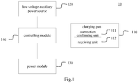
- Fig.1 is a block diagram of a charging device according to a first embodiment of the present disclosure.
- the charging device 10 comprises a charging gun 110, a low voltage auxiliary power source 120, a power module 130 and a controlling module140.
- the controlling module 140 is connected with the charging gun 110, the low voltage auxiliary power source 120 and the power module 130 respectively.
- the charging gun 110 further comprises a connection confirming unit 111 and a receiving unit 112.
- the power module 130 is configured to convert an AC electricity to a DC electricity.
- the controlling module 140 is configured to control the low voltage auxiliary power source 120 to supply power to a circuit connected with the controlling module 140.
- the connection confirming unit 111 sends a connection confirming signal to the controlling module 140.
- the controlling module 140 triggers a first request to the receiving unit 112. If the receiving unit 112 receives the first request from the controlling module 140, it sends a first report in response to the first request to the controlling module 140. After receiving the first report, the controlling module 140 controls the power module 130 to convert the AC electricity to the DC electricity to charge the peripheral device.
- controlling module 140 may be further configured to judge whether the first request is a request of a last item to be sent to the receiving unit 112. The number and sequence of the requests are pre-set by the controlling module 140. If the first request is not the last request, the controlling module 140 may further reset the low voltage auxiliary power source 120 and trigger a second request to the receiving unit 112.
- the first request and/or the second request may take a form of stopping sending messages to the receiving unit 112, the first report and/or the second report may be a time-out report.
- the messages may be corresponding to working states of the charging gun respectively, and may include but not be limited to a capacity message, a current message and a rating power message.
- the controlling module 140 may stop sending a first message (e.g. the current message) to the receiving unit 112 so as to detect whether the working state corresponding to the first message is normal. If the first report is received by the controlling module 140 in a preset time period, the controlling module 140 determines that the working state corresponding to the first message is normal, and then controls the power module 130 to convert the AC electricity to the DC electricity to charge the peripheral device.
- the charging device uses the low voltage auxiliary power source and the power module in itself to supply power, which may facilitate a moving of the charging device as well as a charging to the peripheral device.
- the charging device uses the controlling module to automatically detect the working state of the charging device before charging the peripheral device, it may increase a safety of the charging.
- Fig.2 is a block diagram of a charging device according to a second embodiment of the present disclosure. As shown in Fig.2 , the difference between the first embodiment and the second embodiment is that the charging device further comprises a display module 160 and a leakage detecting module 170.
- the display module 160 is configured to display items for instructing the controlling module 140.
- the leakage detecting module 170 is connected with the controlling module 140, and is controlled by the controlling module 140 to detect a leakage of the charging device 10.
- the display module 160 may be an interactive interface.
- the display module 160 may comprise a plurality of pilot lamps, in which each pilot lamp may indicate a working state for each item.
- each pilot lamp may indicate a working state for each item.
- the corresponding pilot lamp is lighted, and when the working state is faulty, the corresponding lamp is dark.
- people could simply recognize which item of the working states is faulty, which may otherwise be time and cost consuming.
- Fig.3 is a block diagram of a charging device according to a third embodiment of the present disclosure.
- the charging device 20 comprises a charging gun 210, a connection determining unit 220, a low voltage power source unit 230, a sending unit 240, a timing unit 250, a receiving unit 260 and a control unit 270.
- the charging gun 210 is configured to charge a peripheral device (not shown).
- the connection determining unit 220 is configured to determine whether the charging gun 210 is connected with the peripheral device.
- the low voltage power source unit 230 is configured to enable a communication between the charging device 20 and the peripheral device when the charging gun 210 is connected with the peripheral device.
- the low voltage power source unit 230 may provide electricity enough for the communication to the peripheral device.
- the sending unit 240 is configured to send a first message periodically to the peripheral device.
- the timing unit 250 is configured to stop the sending unit 240 from sending the first message after a first time period.
- the receiving unit 260 is configured to receive a first report from the peripheral device, which is in response to stopping the sending unit 240 from sending the first message after the first time period.
- the control unit 270 is configured to determine whether the receiving unit 260 receives the first report within a second time period after stopping the sending unit 240 from sending the first message and if yes, control the charging gun 210 to charge the peripheral device.
- the first message may be one of a capacity message, a current message, a rating power message and so on, which is corresponding to a working state respectively. Therefore, when the control unit 270 receives the first report in response to stopping the sending unit 240 from sending the first message after the first time period, it indicates that the connection between the charging device 20 and the peripheral device is normal, and thus the charging to the peripheral device could be performed.
- the peripheral may be an electric vehicle, and the charging device may communicate with a battery management system in the electric vehicle, such as through a control area network (CAN).
- CAN control area network
- the charging gun according to an embodiment of the present disclosure has the low voltage power source unit in itself, which may facilitate the moving of the charging device as well as the charging to the peripheral device.
- the charging device according to the embodiment of the present disclosure automatically detect whether the connection with peripheral device is normal before charging the peripheral device, it may increase the safety of the charging.
- Fig.4 is a block diagram of a charging device according to a fourth embodiment of the present disclosure.
- the charging device further comprises a judging unit 280, a reset unit 290 and a displaying unit 300.
- the judging unit 280 is configured to judge whether the first message is a message of a last item to be sent to the peripheral device. The number and sequence of the messages are pre-set.
- the reset unit 290 is configured to reset the low voltage power source unit 230 if the first message is not the message of the last item. Furthermore, after resetting the low voltage power source unit 230, the sending unit 240 sends a second message periodically to the peripheral device.
- the timing unit 250 stops the sending unit 240 from sending the second message. Then, the control unit 270 determines whether the receiving unit 260 receives a second report within the second time period from the peripheral device after stopping the sending unit from sending the second message and if yes, the control unit 270 controls the charging gun 210 to charge the peripheral device.
- the second message may also be one of the capacity message, the current message, the rating power message and so on, and the second message is different from the first message.
- the displaying unit 300 is configured to display information indicating whether the receiving unit 260 receives the first report or the second report within the second time period.
- the displaying unit 300 may comprise a plurality of pilot lamps, each pilot lamps is corresponding to a working state of each item respectively. When the working state of an item is normal, the corresponding pilot lamp is lighted, and when the working state is fault, the corresponding lamp is dark. Hence, people could simply recognize which item of the working states is faulty, which may otherwise be time and cost consuming.
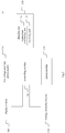
- Fig.5 is a flow chart of the method for controlling a charging device according to an embodiment of the present disclosure.
- the charging device comprises: a charging gun comprising a connection confirming unit and a receiving unit; a low voltage auxiliary power source; a power module configured to convert an AC electricity to a DC electricity; and a controlling module connected with the charging gun, the low voltage auxiliary power source and the power module respectively.
- the method for controlling the charging device comprises the following steps:
- the first report is a time-out report. If the time-out report is received by the controlling module in a preset time period, the controlling module determines that the working state corresponding to the first message is normal and controls the power module to convert the AC electricity to the DC electricity to charge the peripheral device by the controlling module.
- the method for controlling the charging device may further comprise a step of judging whether the first request is a request of a last item to be sent to the receiving unit (S17), the number and sequence of the requests are pre-set. If no, the controlling module sends a second request to the receiving unit (S18) and then the controlling unit judges whether a second report in response to the second request is received (S19). If the second report in response to the second request is received by the controlling module, the controlling module controls the power module to convert the AC electricity to the DC electricity to charge the peripheral device by the controlling module (S110).
- the second request may also take a form of stopping sending messages to the receiving unit.
- the charging device may further comprise a display module for displaying items for instructing the controlling module. Hence, people could simply recognize which item of the working states is faulty, which may otherwise be time and cost consuming.
- the charging device may further comprise a leakage detecting module connected with the controlling module. The controlling module controls the leakage detecting module to detect a leakage of the charging device. Hence, the safety of the charging could be further enhanced.
- the method for controlling a charging device judges whether the charging device is suitable for charging the peripheral device before the charging, which may increase the safety of the charging.
- the charging device may facilitate the moving of the charging device as well as the charging to the peripheral device.
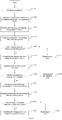
- Fig.6 is a flow chart of the method for detecting a peripheral device to be charged by a charging device according to an embodiment of the present disclosure. As shown in Fig.6 , the method for detecting a peripheral device to be charged by a charging device may comprise the following steps:
- the method for detecting the peripheral device to be charged by the charging device may further comprise a step of displaying an error if the first report in response to stopping sending the first message after the first time period is not received within the second time period from the peripheral device (S27) and a step of displaying that the first report is received within the second time period (S28).
- the method for detecting the peripheral device to be charged by the charging device may also further comprise a step of determining whether the first message is a message of a last item (S29), the number and sequence of messages are pre-set. If the first message is the message of the last item, performing a step of displaying that the detecting ends (S210). If the first message is not the message of the last item, sending a second message periodically to the peripheral device (S211), and stopping sending the second message after the first time period (S212).
- the method may comprise a step of judging whether the second message is the message of the last item and this kind of judge will be repeated until the message is the message of the last item as pre-set.
- the method for detecting the peripheral device to be charged by the charging device detects whether the connection between the charging device and the peripheral device is normal, which may increase the safety of the charging.
Landscapes
- Engineering & Computer Science (AREA)
- Power Engineering (AREA)
- Transportation (AREA)
- Mechanical Engineering (AREA)
- Life Sciences & Earth Sciences (AREA)
- Sustainable Development (AREA)
- Sustainable Energy (AREA)
- Charge And Discharge Circuits For Batteries Or The Like (AREA)
- Electric Propulsion And Braking For Vehicles (AREA)
Claims (14)
- Procédé pour détecter un dispositif périphérique devant être chargé par un dispositif de charge, comportant les étapes consistant à :détecter si le dispositif de charge est connecté à un dispositif périphérique (S21) ;si oui, activer une communication entre le dispositif de charge et le dispositif périphérique (S22) ;envoyer périodiquement un premier message au dispositif périphérique (S23) ;arrêter l'envoi du premier message après une première période de temps (S24) ;déterminer si un premier rapport en réponse à l'arrêt de l'envoi du premier message après la première période de temps est reçu du dispositif périphérique sur une seconde période de temps (S25) ; etsi oui, commander le dispositif de charge de manière à charger le dispositif périphérique (S26).
- Procédé selon la revendication 1, comportant en outre :si le premier rapport en réponse à l'arrêt de l'envoi du premier message après la première période de temps n'est pas reçu du dispositif périphérique sur la seconde période de temps, afficher une erreur (S27).
- Procédé selon la revendication 1 ou 2, comportant en outre l'étape consistant à :afficher que le premier rapport est reçu sur la seconde période de temps (S28).
- Procédé selon l'une quelconque des revendications 1 à 3, comportant en outre l'étape consistant à :déterminer si le premier message est un message d'un dernier élément (S29) ; etsi oui, afficher que la détection se termine (S210).
- Procédé selon l'une quelconque des revendications 1 à 4, comportant en outre les étapes consistant à :si le premier message n'est pas le message du dernier élément, réinitialiser la communication entre le dispositif de charge et le dispositif périphérique ;envoyer périodiquement un second message au dispositif périphérique (S211) ;arrêter l'envoi du second message après la première période de temps (S212) ;déterminer si un second rapport en réponse à l'arrêt de l'envoi du second message après la première période de temps est reçu du dispositif périphérique sur la seconde période de temps (S213) ;si oui, commander le dispositif de charge de manière à charger le dispositif périphérique (S214) ; etsi non, afficher l'erreur (5215).
- Procédé selon l'une quelconque des revendications 1 à 5, dans lequel le premier message ou le second message est un message parmi un message de capacité, un message d'intensité et un message de puissance nominale.
- Procédé selon l'une quelconque des revendications 1 à 6, dans lequel le dispositif périphérique est un véhicule électrique.
- Procédé selon la revendication 7, dans lequel le dispositif de charge communique avec un système de gestion de batterie dans le véhicule électrique.
- Dispositif de charge (20) comportant :un pistolet de charge (210), pour charger un dispositif périphérique ;une unité de détermination de connexion (220), pour déterminer si le pistolet de charge (210) est connecté au dispositif périphérique ;une unité de source d'alimentation à basse tension (230), pour activer une communication entre le dispositif de charge (20) et le dispositif périphérique lorsque le pistolet de charge (210) est connecté au dispositif périphérique ;une unité d'envoi (240), pour envoyer périodiquement un premier message au dispositif périphérique ;une unité de temporisation (240), pour arrêter l'envoi du premier message par l'unité d'envoi (240) après une première période de temps ;une unité de réception (260), pour recevoir du dispositif périphérique un premier rapport en réponse à l'arrêt de l'envoi du premier message par l'unité d'envoi (240) après une première période de temps ; etune unité de commande (270), pour déterminer si l'unité de réception (260) reçoit le premier rapport sur une seconde période de temps après l'arrêt de l'envoi du premier message par l'unité d'envoi (240) et si oui, commander le pistolet de charge (210) de manière à charger le dispositif périphérique.
- Dispositif de charge (20) selon la revendication 9, comportant en outre :une unité de jugement (280), pour juger si le premier message est un message d'un dernier élément devant être envoyé au dispositif périphérique ; etune unité de réinitialisation (290), pour réinitialiser l'unité de source d'alimentation à basse tension (230) si le premier message n'est pas le message du dernier élément, dans lequel l'unité d'envoi (240) envoie périodiquement un second message au dispositif périphérique ; l'unité de temporisation (250) arrête l'envoi du second message par l'unité d'envoi (240) après une période première de temps ;l'unité de commande (270) détermine si l'unité de réception (260) reçoit un second rapport provenant du dispositif périphérique sur la seconde période de temps après l'arrêt de l'envoi du second message par l'unité d'envoi (240) et si oui, commande le pistolet de chargement (210) de manière à charger le dispositif périphérique.
- Dispositif de charge (20) selon la revendication 9 ou 10, dans lequel le premier message ou le second message est un message parmi un message de capacité, un message d'intensité et un message de puissance nominale.
- Dispositif de charge (20) selon l'une quelconque des revendications 9 à 11, comportant en outre :une unité d'affichage (300), pour afficher des informations indiquant si l'unité de réception (260) reçoit le premier rapport ou le second rapport sur la seconde période de temps.
- Dispositif de charge (20) selon l'une quelconque des revendications 9 à 12, dans lequel le dispositif périphérique est un véhicule électrique.
- Dispositif de charge (20) selon la revendication 13, dans lequel le dispositif de charge communique avec un système de gestion de batterie dans le véhicule électrique.
Applications Claiming Priority (2)
| Application Number | Priority Date | Filing Date | Title |
|---|---|---|---|
| CN201110445376.XA CN103187777B (zh) | 2011-12-28 | 2011-12-28 | 一种充电机及检测方法 |
| PCT/CN2012/085875 WO2013097583A1 (fr) | 2011-12-28 | 2012-12-04 | Dispositif de chargement, procédé de commande de dispositif de chargement, et procédé de détection de dispositif périphérique |
Publications (3)
| Publication Number | Publication Date |
|---|---|
| EP2798720A1 EP2798720A1 (fr) | 2014-11-05 |
| EP2798720A4 EP2798720A4 (fr) | 2015-11-25 |
| EP2798720B1 true EP2798720B1 (fr) | 2017-10-25 |
Family
ID=48678798
Family Applications (1)
| Application Number | Title | Priority Date | Filing Date |
|---|---|---|---|
| EP12861647.1A Active EP2798720B1 (fr) | 2011-12-28 | 2012-12-04 | Dispositif de chargement, procédé de commande de dispositif de chargement, et procédé de détection de dispositif périphérique |
Country Status (6)
| Country | Link |
|---|---|
| US (1) | US9583956B2 (fr) |
| EP (1) | EP2798720B1 (fr) |
| JP (1) | JP6041892B2 (fr) |
| KR (1) | KR101591216B1 (fr) |
| CN (1) | CN103187777B (fr) |
| WO (1) | WO2013097583A1 (fr) |
Families Citing this family (19)
| Publication number | Priority date | Publication date | Assignee | Title |
|---|---|---|---|---|
| CN103187777B (zh) | 2011-12-28 | 2016-04-27 | 比亚迪股份有限公司 | 一种充电机及检测方法 |
| DE102014016620B4 (de) | 2014-10-24 | 2021-08-26 | Audi Ag | Verfahren zum Betrieb einer Energiespeichereinrichtung in einem Kraftfahrzeug und Kraftfahrzeug |
| CN104648178B (zh) * | 2015-02-11 | 2017-03-08 | 安徽江淮汽车集团股份有限公司 | 一种基于纯电动汽车的充电上电控制方法 |
| CN104950204B (zh) * | 2015-06-30 | 2017-08-11 | 郑州日产汽车有限公司 | 国标充电枪信号检测装置 |
| CN105291875B (zh) * | 2015-11-24 | 2017-12-12 | 安徽江淮汽车集团股份有限公司 | 一种电动汽车快速充电方法 |
| CN106891744B (zh) * | 2015-12-18 | 2019-11-08 | 比亚迪股份有限公司 | 电动汽车及其车载充电器和车载充电器的控制方法 |
| CN106891748B (zh) * | 2015-12-18 | 2019-02-26 | 比亚迪股份有限公司 | 电动汽车及其车载充电器和车载充电器的控制方法 |
| DE102016106700A1 (de) * | 2016-04-12 | 2017-10-12 | Rwe International Se | Ladestation und Verfahren zum Betreiben einer Ladestation |
| KR101706543B1 (ko) * | 2016-09-08 | 2017-02-16 | 주식회사 에스비테크 | 전지용 충전기 |
| CN106872832A (zh) * | 2017-03-27 | 2017-06-20 | 江苏万帮德和新能源科技有限公司 | 非车载充电机的模拟检测方法、装置以及系统 |
| KR102449128B1 (ko) * | 2018-05-25 | 2022-09-29 | 삼성에스디아이 주식회사 | 전기적 연결성 검증 장치 |
| CN109494828A (zh) * | 2018-10-17 | 2019-03-19 | 北京车和家信息技术有限公司 | 充电控制方法、遥控钥匙及车辆 |
| CN110588375A (zh) * | 2019-08-07 | 2019-12-20 | 云杉智慧新能源技术有限公司 | 一种移动补电车充电机 |
| CN112600487B (zh) * | 2020-12-07 | 2022-11-11 | 中国科学院长春光学精密机械与物理研究所 | 一种电机飞车保护系统和方法 |
| CN113438127A (zh) * | 2021-06-18 | 2021-09-24 | 中国第一汽车股份有限公司 | 一种电动车直流充电通信智能化测试方法、装置、终端及储存介质 |
| CN114043895B (zh) * | 2021-10-26 | 2024-06-04 | 深圳市道通合创数字能源有限公司 | 一种还枪检测方法、装置、充电桩及充电桩管理系统 |
| CN114851851A (zh) * | 2022-07-07 | 2022-08-05 | 中国重汽集团济南动力有限公司 | 一种新能源车辆绝缘问题排查系统与方法 |
| CN115431814B (zh) * | 2022-09-21 | 2024-05-17 | 重庆长安汽车股份有限公司 | 车辆的充电方法及装置 |
| CN115436674B (zh) * | 2022-11-03 | 2023-02-17 | 淮安市成翔精密制造有限公司 | 一种新能源汽车充电枪端子加工用的双头同步检测装置 |
Family Cites Families (19)
| Publication number | Priority date | Publication date | Assignee | Title |
|---|---|---|---|---|
| JP3028704B2 (ja) * | 1993-05-10 | 2000-04-04 | 住友電装株式会社 | 電気自動車充電用コネクタ |
| JPH10215523A (ja) | 1997-01-29 | 1998-08-11 | Nec Yonezawa Ltd | 多種のバッテリパックに充電可能な充電器とその充電方 式 |
| US7267090B2 (en) * | 2005-11-21 | 2007-09-11 | Gm Global Technology Operations, Inc. | Method of starting a hybrid vehicle |
| JP4375472B2 (ja) * | 2007-10-23 | 2009-12-02 | トヨタ自動車株式会社 | 車両の充電制御装置 |
| JP4333798B2 (ja) * | 2007-11-30 | 2009-09-16 | トヨタ自動車株式会社 | 充電制御装置および充電制御方法 |
| JP2009201198A (ja) * | 2008-02-19 | 2009-09-03 | Rohm Co Ltd | 車両用の充電システム |
| JP2010103870A (ja) * | 2008-10-27 | 2010-05-06 | Pioneer Electronic Corp | 車載情報装置、車外側情報装置、電気自動車充電システム、及び、電気自動車充電システムの情報転送方法 |
| CN101740947B (zh) * | 2008-11-25 | 2012-08-01 | 比亚迪股份有限公司 | 用于可电力驱动的车辆的充电装置 |
| JP5643948B2 (ja) * | 2009-03-23 | 2014-12-24 | 日東工業株式会社 | 充電装置 |
| US8384358B2 (en) * | 2009-05-28 | 2013-02-26 | GM Global Technology Operations LLC | Systems and methods for electric vehicle charging and for providing notification of variations from charging expectations |
| JP5378965B2 (ja) * | 2009-11-30 | 2013-12-25 | 株式会社東海理化電機製作所 | 充電システム |
| JP2011128793A (ja) | 2009-12-16 | 2011-06-30 | Sony Corp | 電動移動体、課税サーバ、充電装置、駆動管理方法、及びプログラム |
| CN101807791B (zh) * | 2010-03-19 | 2012-05-02 | 天津清源电动车辆有限责任公司 | 电动汽车直流充电接口安全接插保护装置 |
| JP5647057B2 (ja) * | 2010-05-19 | 2014-12-24 | 株式会社日立製作所 | 充電装置、充電制御ユニット及び充電制御方法 |
| JP2012019636A (ja) * | 2010-07-08 | 2012-01-26 | Denso Corp | 車両用充電装置 |
| CN201918773U (zh) * | 2010-11-16 | 2011-08-03 | 上海畅聪新能源科技有限公司 | 自助智能充电系统及其充电桩 |
| CN201877858U (zh) * | 2010-12-14 | 2011-06-22 | 山东电力研究院 | 一种带有多路控制多充电插口的电动汽车充电桩 |
| CN102255113A (zh) * | 2011-04-07 | 2011-11-23 | 广东省电力设计研究院 | 电动汽车充电方法及其系统、充电机和bms通信模块 |
| CN103187777B (zh) | 2011-12-28 | 2016-04-27 | 比亚迪股份有限公司 | 一种充电机及检测方法 |
-
2011
- 2011-12-28 CN CN201110445376.XA patent/CN103187777B/zh active Active
-
2012
- 2012-12-04 JP JP2014547690A patent/JP6041892B2/ja active Active
- 2012-12-04 WO PCT/CN2012/085875 patent/WO2013097583A1/fr not_active Ceased
- 2012-12-04 KR KR1020147015938A patent/KR101591216B1/ko active Active
- 2012-12-04 EP EP12861647.1A patent/EP2798720B1/fr active Active
-
2014
- 2014-06-18 US US14/308,677 patent/US9583956B2/en active Active
Non-Patent Citations (1)
| Title |
|---|
| None * |
Also Published As
| Publication number | Publication date |
|---|---|
| JP6041892B2 (ja) | 2016-12-14 |
| JP2015502734A (ja) | 2015-01-22 |
| CN103187777A (zh) | 2013-07-03 |
| EP2798720A4 (fr) | 2015-11-25 |
| KR20140097347A (ko) | 2014-08-06 |
| CN103187777B (zh) | 2016-04-27 |
| WO2013097583A1 (fr) | 2013-07-04 |
| EP2798720A1 (fr) | 2014-11-05 |
| KR101591216B1 (ko) | 2016-02-02 |
| US20140292261A1 (en) | 2014-10-02 |
| US9583956B2 (en) | 2017-02-28 |
Similar Documents
| Publication | Publication Date | Title |
|---|---|---|
| EP2798720B1 (fr) | Dispositif de chargement, procédé de commande de dispositif de chargement, et procédé de détection de dispositif périphérique | |
| US20220250498A1 (en) | Charge-discharge apparatus, charge-discharge control method, and computer readable medium | |
| CN112677806A (zh) | 一种电动车充电系统及其控制方法 | |
| US9821676B2 (en) | Electric vehicle charging apparatus having a welding monitoring relay that is opened and closed during charging operations | |
| CN109334505A (zh) | 充电唤醒方法 | |
| CN104638718A (zh) | 一种电动车电池智能管理系统和方法 | |
| CN211075601U (zh) | 一种电动车智能充电设备 | |
| US11626837B2 (en) | Photovoltaic system and method for locating devices in photovoltaic string | |
| CN103545893A (zh) | 一种移动终端充电安全控制方法及系统 | |
| EP3961916A1 (fr) | Système photovoltaïque, procédé permettant de localiser des dispositifs dans une chaîne photovoltaïque, appareil mlpe et procédé pour classer des appareils mlpe | |
| CN105291875A (zh) | 一种电动汽车快速充电方法 | |
| CN104052092A (zh) | 车载动力电池的充电系统及其车载动力电池的充电方法 | |
| US20210086653A1 (en) | Charging device for electric vehicles and automatic trobleshooting method thereof | |
| CN115663943A (zh) | 一种可选充电接口的物联网充电站及充电管理方法 | |
| CN106374152A (zh) | 一种电池异常处理方法、装置、移动终端和系统 | |
| US20190001834A1 (en) | Charge/discharge apparatus | |
| EP3226179A1 (fr) | Appareil électronique | |
| US10664930B2 (en) | Device for powering an electrical appliance | |
| CN112744092A (zh) | 一种交直流通用充电桩的充电方法及系统 | |
| CN116260209A (zh) | Soc显示方法、可插拔式电源系统、设备和存储介质 | |
| KR20200046619A (ko) | 배터리 단자 고정 구조의 외부전원이 필요 없는 배터리 관리 장치 | |
| CN112701746B (zh) | 电池的均衡控制方法和装置、存储介质、电子装置 | |
| CN214154106U (zh) | 一种家用新能源汽车充电电源的mcu控制系统 | |
| US20250162433A1 (en) | Charging system, charging control method, and vehicle | |
| EP4559729A1 (fr) | Système de charge, procédé de commande de charge et véhicule |
Legal Events
| Date | Code | Title | Description |
|---|---|---|---|
| PUAI | Public reference made under article 153(3) epc to a published international application that has entered the european phase |
Free format text: ORIGINAL CODE: 0009012 |
|
| 17P | Request for examination filed |
Effective date: 20140716 |
|
| AK | Designated contracting states |
Kind code of ref document: A1 Designated state(s): AL AT BE BG CH CY CZ DE DK EE ES FI FR GB GR HR HU IE IS IT LI LT LU LV MC MK MT NL NO PL PT RO RS SE SI SK SM TR |
|
| DAX | Request for extension of the european patent (deleted) | ||
| RA4 | Supplementary search report drawn up and despatched (corrected) |
Effective date: 20151022 |
|
| RIC1 | Information provided on ipc code assigned before grant |
Ipc: H02J 7/04 20060101ALI20151016BHEP Ipc: B60L 3/12 20060101ALI20151016BHEP Ipc: H02J 7/02 20060101AFI20151016BHEP Ipc: B60L 11/18 20060101ALI20151016BHEP Ipc: B60L 3/00 20060101ALI20151016BHEP Ipc: H02J 7/00 20060101ALI20151016BHEP |
|
| RIC1 | Information provided on ipc code assigned before grant |
Ipc: H02J 7/02 20160101AFI20170315BHEP Ipc: B60L 3/00 20060101ALI20170315BHEP Ipc: B60L 11/18 20060101ALI20170315BHEP Ipc: H02J 7/04 20060101ALI20170315BHEP Ipc: H02J 7/00 20060101ALI20170315BHEP Ipc: B60L 3/12 20060101ALI20170315BHEP |
|
| GRAP | Despatch of communication of intention to grant a patent |
Free format text: ORIGINAL CODE: EPIDOSNIGR1 |
|
| STAA | Information on the status of an ep patent application or granted ep patent |
Free format text: STATUS: GRANT OF PATENT IS INTENDED |
|
| INTG | Intention to grant announced |
Effective date: 20170516 |
|
| GRAS | Grant fee paid |
Free format text: ORIGINAL CODE: EPIDOSNIGR3 |
|
| GRAA | (expected) grant |
Free format text: ORIGINAL CODE: 0009210 |
|
| STAA | Information on the status of an ep patent application or granted ep patent |
Free format text: STATUS: THE PATENT HAS BEEN GRANTED |
|
| AK | Designated contracting states |
Kind code of ref document: B1 Designated state(s): AL AT BE BG CH CY CZ DE DK EE ES FI FR GB GR HR HU IE IS IT LI LT LU LV MC MK MT NL NO PL PT RO RS SE SI SK SM TR |
|
| REG | Reference to a national code |
Ref country code: GB Ref legal event code: FG4D |
|
| REG | Reference to a national code |
Ref country code: CH Ref legal event code: EP |
|
| REG | Reference to a national code |
Ref country code: AT Ref legal event code: REF Ref document number: 940751 Country of ref document: AT Kind code of ref document: T Effective date: 20171115 |
|
| REG | Reference to a national code |
Ref country code: IE Ref legal event code: FG4D |
|
| REG | Reference to a national code |
Ref country code: DE Ref legal event code: R096 Ref document number: 602012039057 Country of ref document: DE |
|
| REG | Reference to a national code |
Ref country code: FR Ref legal event code: PLFP Year of fee payment: 6 |
|
| REG | Reference to a national code |
Ref country code: NL Ref legal event code: FP |
|
| REG | Reference to a national code |
Ref country code: LT Ref legal event code: MG4D |
|
| REG | Reference to a national code |
Ref country code: AT Ref legal event code: MK05 Ref document number: 940751 Country of ref document: AT Kind code of ref document: T Effective date: 20171025 |
|
| PG25 | Lapsed in a contracting state [announced via postgrant information from national office to epo] |
Ref country code: NO Free format text: LAPSE BECAUSE OF FAILURE TO SUBMIT A TRANSLATION OF THE DESCRIPTION OR TO PAY THE FEE WITHIN THE PRESCRIBED TIME-LIMIT Effective date: 20180125 Ref country code: LT Free format text: LAPSE BECAUSE OF FAILURE TO SUBMIT A TRANSLATION OF THE DESCRIPTION OR TO PAY THE FEE WITHIN THE PRESCRIBED TIME-LIMIT Effective date: 20171025 Ref country code: FI Free format text: LAPSE BECAUSE OF FAILURE TO SUBMIT A TRANSLATION OF THE DESCRIPTION OR TO PAY THE FEE WITHIN THE PRESCRIBED TIME-LIMIT Effective date: 20171025 Ref country code: SE Free format text: LAPSE BECAUSE OF FAILURE TO SUBMIT A TRANSLATION OF THE DESCRIPTION OR TO PAY THE FEE WITHIN THE PRESCRIBED TIME-LIMIT Effective date: 20171025 Ref country code: ES Free format text: LAPSE BECAUSE OF FAILURE TO SUBMIT A TRANSLATION OF THE DESCRIPTION OR TO PAY THE FEE WITHIN THE PRESCRIBED TIME-LIMIT Effective date: 20171025 |
|
| PG25 | Lapsed in a contracting state [announced via postgrant information from national office to epo] |
Ref country code: BG Free format text: LAPSE BECAUSE OF FAILURE TO SUBMIT A TRANSLATION OF THE DESCRIPTION OR TO PAY THE FEE WITHIN THE PRESCRIBED TIME-LIMIT Effective date: 20180125 Ref country code: RS Free format text: LAPSE BECAUSE OF FAILURE TO SUBMIT A TRANSLATION OF THE DESCRIPTION OR TO PAY THE FEE WITHIN THE PRESCRIBED TIME-LIMIT Effective date: 20171025 Ref country code: AT Free format text: LAPSE BECAUSE OF FAILURE TO SUBMIT A TRANSLATION OF THE DESCRIPTION OR TO PAY THE FEE WITHIN THE PRESCRIBED TIME-LIMIT Effective date: 20171025 Ref country code: GR Free format text: LAPSE BECAUSE OF FAILURE TO SUBMIT A TRANSLATION OF THE DESCRIPTION OR TO PAY THE FEE WITHIN THE PRESCRIBED TIME-LIMIT Effective date: 20180126 Ref country code: LV Free format text: LAPSE BECAUSE OF FAILURE TO SUBMIT A TRANSLATION OF THE DESCRIPTION OR TO PAY THE FEE WITHIN THE PRESCRIBED TIME-LIMIT Effective date: 20171025 Ref country code: HR Free format text: LAPSE BECAUSE OF FAILURE TO SUBMIT A TRANSLATION OF THE DESCRIPTION OR TO PAY THE FEE WITHIN THE PRESCRIBED TIME-LIMIT Effective date: 20171025 Ref country code: IS Free format text: LAPSE BECAUSE OF FAILURE TO SUBMIT A TRANSLATION OF THE DESCRIPTION OR TO PAY THE FEE WITHIN THE PRESCRIBED TIME-LIMIT Effective date: 20180225 |
|
| REG | Reference to a national code |
Ref country code: DE Ref legal event code: R097 Ref document number: 602012039057 Country of ref document: DE |
|
| PG25 | Lapsed in a contracting state [announced via postgrant information from national office to epo] |
Ref country code: CZ Free format text: LAPSE BECAUSE OF FAILURE TO SUBMIT A TRANSLATION OF THE DESCRIPTION OR TO PAY THE FEE WITHIN THE PRESCRIBED TIME-LIMIT Effective date: 20171025 Ref country code: SK Free format text: LAPSE BECAUSE OF FAILURE TO SUBMIT A TRANSLATION OF THE DESCRIPTION OR TO PAY THE FEE WITHIN THE PRESCRIBED TIME-LIMIT Effective date: 20171025 Ref country code: DK Free format text: LAPSE BECAUSE OF FAILURE TO SUBMIT A TRANSLATION OF THE DESCRIPTION OR TO PAY THE FEE WITHIN THE PRESCRIBED TIME-LIMIT Effective date: 20171025 Ref country code: CY Free format text: LAPSE BECAUSE OF FAILURE TO SUBMIT A TRANSLATION OF THE DESCRIPTION OR TO PAY THE FEE WITHIN THE PRESCRIBED TIME-LIMIT Effective date: 20171025 Ref country code: EE Free format text: LAPSE BECAUSE OF FAILURE TO SUBMIT A TRANSLATION OF THE DESCRIPTION OR TO PAY THE FEE WITHIN THE PRESCRIBED TIME-LIMIT Effective date: 20171025 |
|
| REG | Reference to a national code |
Ref country code: CH Ref legal event code: PL |
|
| PG25 | Lapsed in a contracting state [announced via postgrant information from national office to epo] |
Ref country code: RO Free format text: LAPSE BECAUSE OF FAILURE TO SUBMIT A TRANSLATION OF THE DESCRIPTION OR TO PAY THE FEE WITHIN THE PRESCRIBED TIME-LIMIT Effective date: 20171025 Ref country code: IT Free format text: LAPSE BECAUSE OF FAILURE TO SUBMIT A TRANSLATION OF THE DESCRIPTION OR TO PAY THE FEE WITHIN THE PRESCRIBED TIME-LIMIT Effective date: 20171025 Ref country code: PL Free format text: LAPSE BECAUSE OF FAILURE TO SUBMIT A TRANSLATION OF THE DESCRIPTION OR TO PAY THE FEE WITHIN THE PRESCRIBED TIME-LIMIT Effective date: 20171025 Ref country code: SM Free format text: LAPSE BECAUSE OF FAILURE TO SUBMIT A TRANSLATION OF THE DESCRIPTION OR TO PAY THE FEE WITHIN THE PRESCRIBED TIME-LIMIT Effective date: 20171025 |
|
| PLBE | No opposition filed within time limit |
Free format text: ORIGINAL CODE: 0009261 |
|
| STAA | Information on the status of an ep patent application or granted ep patent |
Free format text: STATUS: NO OPPOSITION FILED WITHIN TIME LIMIT |
|
| REG | Reference to a national code |
Ref country code: IE Ref legal event code: MM4A |
|
| PG25 | Lapsed in a contracting state [announced via postgrant information from national office to epo] |
Ref country code: MT Free format text: LAPSE BECAUSE OF NON-PAYMENT OF DUE FEES Effective date: 20171204 Ref country code: LU Free format text: LAPSE BECAUSE OF NON-PAYMENT OF DUE FEES Effective date: 20171204 |
|
| 26N | No opposition filed |
Effective date: 20180726 |
|
| REG | Reference to a national code |
Ref country code: BE Ref legal event code: MM Effective date: 20171231 |
|
| PG25 | Lapsed in a contracting state [announced via postgrant information from national office to epo] |
Ref country code: IE Free format text: LAPSE BECAUSE OF NON-PAYMENT OF DUE FEES Effective date: 20171204 |
|
| PG25 | Lapsed in a contracting state [announced via postgrant information from national office to epo] |
Ref country code: SI Free format text: LAPSE BECAUSE OF FAILURE TO SUBMIT A TRANSLATION OF THE DESCRIPTION OR TO PAY THE FEE WITHIN THE PRESCRIBED TIME-LIMIT Effective date: 20171025 Ref country code: LI Free format text: LAPSE BECAUSE OF NON-PAYMENT OF DUE FEES Effective date: 20171231 Ref country code: BE Free format text: LAPSE BECAUSE OF NON-PAYMENT OF DUE FEES Effective date: 20171231 Ref country code: CH Free format text: LAPSE BECAUSE OF NON-PAYMENT OF DUE FEES Effective date: 20171231 |
|
| PG25 | Lapsed in a contracting state [announced via postgrant information from national office to epo] |
Ref country code: MC Free format text: LAPSE BECAUSE OF FAILURE TO SUBMIT A TRANSLATION OF THE DESCRIPTION OR TO PAY THE FEE WITHIN THE PRESCRIBED TIME-LIMIT Effective date: 20171025 Ref country code: HU Free format text: LAPSE BECAUSE OF FAILURE TO SUBMIT A TRANSLATION OF THE DESCRIPTION OR TO PAY THE FEE WITHIN THE PRESCRIBED TIME-LIMIT; INVALID AB INITIO Effective date: 20121204 |
|
| PG25 | Lapsed in a contracting state [announced via postgrant information from national office to epo] |
Ref country code: MK Free format text: LAPSE BECAUSE OF FAILURE TO SUBMIT A TRANSLATION OF THE DESCRIPTION OR TO PAY THE FEE WITHIN THE PRESCRIBED TIME-LIMIT Effective date: 20171025 |
|
| PG25 | Lapsed in a contracting state [announced via postgrant information from national office to epo] |
Ref country code: TR Free format text: LAPSE BECAUSE OF FAILURE TO SUBMIT A TRANSLATION OF THE DESCRIPTION OR TO PAY THE FEE WITHIN THE PRESCRIBED TIME-LIMIT Effective date: 20171025 |
|
| REG | Reference to a national code |
Ref country code: DE Ref legal event code: R081 Ref document number: 602012039057 Country of ref document: DE Owner name: BYD COMPANY LIMITED, SHENZHEN, CN Free format text: FORMER OWNERS: BYD COMPANY LIMITED, SHENZHEN, GUANGDONG, CN; SHENZHEN BYD AUTO R&D COMPANY LIMITED, SHENZHEN, GUANGDONG, CN |
|
| PG25 | Lapsed in a contracting state [announced via postgrant information from national office to epo] |
Ref country code: PT Free format text: LAPSE BECAUSE OF FAILURE TO SUBMIT A TRANSLATION OF THE DESCRIPTION OR TO PAY THE FEE WITHIN THE PRESCRIBED TIME-LIMIT Effective date: 20171025 |
|
| PG25 | Lapsed in a contracting state [announced via postgrant information from national office to epo] |
Ref country code: AL Free format text: LAPSE BECAUSE OF FAILURE TO SUBMIT A TRANSLATION OF THE DESCRIPTION OR TO PAY THE FEE WITHIN THE PRESCRIBED TIME-LIMIT Effective date: 20171025 |
|
| P01 | Opt-out of the competence of the unified patent court (upc) registered |
Effective date: 20230527 |
|
| PGFP | Annual fee paid to national office [announced via postgrant information from national office to epo] |
Ref country code: GB Payment date: 20251218 Year of fee payment: 14 |
|
| PGFP | Annual fee paid to national office [announced via postgrant information from national office to epo] |
Ref country code: NL Payment date: 20251219 Year of fee payment: 14 Ref country code: FR Payment date: 20251218 Year of fee payment: 14 |
|
| PGFP | Annual fee paid to national office [announced via postgrant information from national office to epo] |
Ref country code: DE Payment date: 20251222 Year of fee payment: 14 |