EP2799005A1 - Verfahren und System zur Signalanalyse und Verarbeitungsmodul - Google Patents
Verfahren und System zur Signalanalyse und Verarbeitungsmodul Download PDFInfo
- Publication number
- EP2799005A1 EP2799005A1 EP13002845.9A EP13002845A EP2799005A1 EP 2799005 A1 EP2799005 A1 EP 2799005A1 EP 13002845 A EP13002845 A EP 13002845A EP 2799005 A1 EP2799005 A1 EP 2799005A1
- Authority
- EP
- European Patent Office
- Prior art keywords
- signal
- input signals
- calculating unit
- electrodes
- filtered
- Prior art date
- Legal status (The legal status is an assumption and is not a legal conclusion. Google has not performed a legal analysis and makes no representation as to the accuracy of the status listed.)
- Granted
Links
Images


Classifications
-
- A—HUMAN NECESSITIES
- A61—MEDICAL OR VETERINARY SCIENCE; HYGIENE
- A61B—DIAGNOSIS; SURGERY; IDENTIFICATION
- A61B5/00—Measuring for diagnostic purposes; Identification of persons
- A61B5/72—Signal processing specially adapted for physiological signals or for diagnostic purposes
- A61B5/7203—Signal processing specially adapted for physiological signals or for diagnostic purposes for noise prevention, reduction or removal
-
- A—HUMAN NECESSITIES
- A61—MEDICAL OR VETERINARY SCIENCE; HYGIENE
- A61B—DIAGNOSIS; SURGERY; IDENTIFICATION
- A61B5/00—Measuring for diagnostic purposes; Identification of persons
- A61B5/24—Detecting, measuring or recording bioelectric or biomagnetic signals of the body or parts thereof
- A61B5/30—Input circuits therefor
- A61B5/307—Input circuits therefor specially adapted for particular uses
- A61B5/308—Input circuits therefor specially adapted for particular uses for electrocardiography [ECG]
-
- A—HUMAN NECESSITIES
- A61—MEDICAL OR VETERINARY SCIENCE; HYGIENE
- A61B—DIAGNOSIS; SURGERY; IDENTIFICATION
- A61B5/00—Measuring for diagnostic purposes; Identification of persons
- A61B5/24—Detecting, measuring or recording bioelectric or biomagnetic signals of the body or parts thereof
- A61B5/316—Modalities, i.e. specific diagnostic methods
- A61B5/318—Heart-related electrical modalities, e.g. electrocardiography [ECG]
- A61B5/346—Analysis of electrocardiograms
-
- A—HUMAN NECESSITIES
- A61—MEDICAL OR VETERINARY SCIENCE; HYGIENE
- A61B—DIAGNOSIS; SURGERY; IDENTIFICATION
- A61B5/00—Measuring for diagnostic purposes; Identification of persons
- A61B5/72—Signal processing specially adapted for physiological signals or for diagnostic purposes
- A61B5/7203—Signal processing specially adapted for physiological signals or for diagnostic purposes for noise prevention, reduction or removal
- A61B5/7207—Signal processing specially adapted for physiological signals or for diagnostic purposes for noise prevention, reduction or removal of noise induced by motion artifacts
-
- A—HUMAN NECESSITIES
- A61—MEDICAL OR VETERINARY SCIENCE; HYGIENE
- A61B—DIAGNOSIS; SURGERY; IDENTIFICATION
- A61B5/00—Measuring for diagnostic purposes; Identification of persons
- A61B5/72—Signal processing specially adapted for physiological signals or for diagnostic purposes
- A61B5/7235—Details of waveform analysis
- A61B5/725—Details of waveform analysis using specific filters therefor, e.g. Kalman or adaptive filters
Definitions
- the invention generally relates to a method and a system for signal analyzing and a processing module of the system, and more particularly, to a method and a system for signal analyzing and a processing module of the system which can filter noise components according to multiple input signals.
- the instruments may obtain a physiological signal, such as an electrocardiogram (ECG) signal, through electrodes directly attached to a patient's chest, arm, or leg. Then, the amplitude of the physiological signals can be measured and transmitted to other circuitry for processing.
- ECG electrocardiogram
- the amplitude the ECG signal transmitted from electrodes is usually measured around millivolts, so that noise components within the ECG signal may play a significant role in affecting the actual waveform of the ECG signal.
- high pass filters or band pass filters are generally used to reduce the noise components caused by external factors, such as power-line interference, ambient electromagnetic activity or movements of electrodes.
- reducing the noise components of the ECG signal which is caused by physiological processes within the patient is a critical issue nowadays, and it is worthy to develop a signal analyzing system and a signal analyzing method which can filter out the noise components.
- a signal analyzing method including the following steps is disclosed. First, a body electrical signal is generated according to at least one of a plurality of first input signals and at least one of a plurality of second input signals. Then, a first filtered signal corresponding to the plurality of first input signals is generated. And, a second filtered signal corresponding to the plurality of second input signals is also generated. Further, a lead signal is generated according to the body electrical signal, the first filtered signal and the second filtered signal.
- the plurality of first input signals are transmitted from a plurality of first electrodes of a first electrode group, and the second input signals are transmitted from a plurality of second electrodes of a second electrode group.
- a signal analyzing system includes a first electrode group having a plurality of first electrodes, a second electrode group having a plurality of second electrodes, and a processing module.
- the plurality of first electrodes is configured to transmit a plurality of first input signals.
- the plurality of second electrodes is configured to transmit a plurality of second input signals.
- the processing module includes a first calculating unit, a second calculating unit, a third calculating unit and a fourth calculating unit.
- the first calculating unit is coupled to the first electrode group and the second electrode group for receiving at least one of the plurality of first input signals and at least one of the plurality of second input signals.
- the first calculating unit is configured to generate a body electrical signal according to at least one of the first input signals and at least one of the second input signals.
- the second calculating unit is coupled to the first electrode group for receiving the plurality of first input signals, and is configured to generate a first filtered signal by filtering a first difference signal corresponding to the plurality of first input signals.
- the third calculating unit is coupled to the second electrode group for receiving the plurality of second input signals, and is configured to generate a second filtered signal by filtering a second difference signal corresponding to the plurality of second input signals.
- the fourth calculating unit is coupled to the first calculating unit, the second calculating unit and the third calculating unit for receiving the body electrical signal, the first filtered signal and the second filtered signal, and is configured to generate a lead signal according to the body electrical signal, the first filtered signal and the second filtered signal.
- a processing module configured to generate a lead signal according to a plurality of first input signals transmitted from a plurality of first electrodes, and according to a plurality of second input signals transmitted from a plurality of second electrodes.
- the processing module includes a first calculating unit, a second calculating unit, a third calculating unit; and a fourth calculating unit.
- the first calculating unit is coupled to the first electrode group and the second electrode group for receiving at least one of the plurality of first input signals and at least one of the plurality of second input signals.
- the first calculating unit is configured to generate a body electrical signal according to at least one of the first input signals and at least one of the second input signals.
- the second calculating unit is coupled to the first electrode group for receiving the plurality of first input signals, and is configured to generate a first filtered signal by filtering a first difference signal corresponding to the plurality of first input signals.
- the third calculating unit is coupled to the second electrode group for receiving the plurality of second input signals, and is configured to generate a second filtered signal by filtering a second difference signal corresponding to the plurality of second input signals.
- the fourth calculating unit is coupled to the first calculating unit, the second calculating unit and the third calculating unit for receiving the body electrical signal, the first filtered signal and the second filtered signal, and is configured to generate a lead signal according to the body electrical signal, the first filtered signal and the second filtered signal.
- FIG. 1 shows a schematic diagram of a signal analyzing system according to an embodiment of the invention
- FIG. 2 shows a schematic diagram of a first electrode group and a second electrode group of FIG. 1 according to an embodiment of the invention
- FIG. 3 shows a circuit diagram of a processing module of the signal analyzing system according to an embodiment of the invention
- FIG. 4 shows a circuit diagram of a portion of a second calculating unit of the processing module of FIG. 3 according to an embodiment of the invention
- FIG. 5A shows an oscillogram of a body electrical signal according to an embodiment of the invention
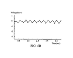
- FIG. 5B shows an oscillogram of motion artifacts within the body electrical signal according to an embodiment of the invention
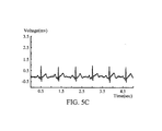
- FIG. 5C shows an oscillogram of a lead signal according to an embodiment of the invention
- FIG. 6 shows a schematic diagram of the first electrode group according to another embodiment of the invention.
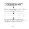
- FIG. 7 shows a flow chart of a signal analyzing method according to an embodiment of the invention.
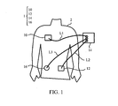
- FIG. 1 shows a schematic diagram of a signal analyzing system according to an embodiment of the invention.
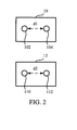
- FIG. 2 shows a schematic diagram of a first electrode group and a second electrode group of FIG. 1 according to an embodiment of the invention.
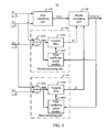
- FIG. 3 shows a circuit diagram of a processing module of the signal analyzing system according to an embodiment of the invention.
- a signal analyzing system 1 has a first electrode group 10, a second electrode group 12, a processing module 14, and a bias electrode 16.
- the first electrode group 10 has a plurality of electrodes (first electrodes), and those electrodes are attached to a human body 2.
- the second electrode group 12 also has a plurality of electrodes (second electrodes), and those electrodes are also attached to the human body 2.
- the first electrode group 10 and the second electrode group 12 may be attached to different areas of the human body 2.
- the first electrode group 10 can, but is not limited to, be attached to the right chest of the human body 2
- the second electrode group 12 can, but is not limited to, be attached to the left abdomen of the human body 2.
- the present embodiment does not limit how the first electrode group 10 and the second electrode group 12 are attached to the human body 2.
- the first electrode group 10 can be attached to the skin of the human body 2 with an electrically conductive gel, so that the first electrode group 10 can obtain signals easily.
- the first electrode group 10 of this embodiment has a first electrode 102 and a second electrode 104.
- the first electrode 102 and the second electrode 104 are disposed within a first predetermined distance, e.g. 1cm or 1.5cm.
- the distance d1 depicted in FIG. 2 is less than or equal to the first predetermined distance.
- the second electrode group 12 of this embodiment can also have two electrodes, including a third electrode 110 and a fourth electrode 112, and the electrodes of the second electrode group 12 shall be disposed within a second predetermined distance.
- the distance d2 depicted in FIG. 2 is less than or equal to the second predetermined distance.
- the present embodiment does not limit whether the second predetermined distance is the same as the first predetermined distance.
- the second predetermined distance may also be 1cm or 1.5cm.
- the first electrode 102 is configured to transmit a first input signal V1 obtained from the human body 2 to the processing module 14 through a transmission wire L1-1.
- the second electrode 104 is configured to transmit a second input signal V2 obtained from the human body 2 to the processing module 14 through a transmission wire L1-2.
- the transmission wire L1-1 and the transmission wire L1-2 are collectively called first transmission line pair L1.
- the wires of the first transmission line pair L1 may be isolated from each other to reduce signal interference.
- the third electrode 110 is configured to transmit a third input signal V3 obtained from the human body 2 to the processing module 14 through a transmission wire L2-1.
- the fourth electrode 112 is configured to transmit a fourth input signal V4 obtained from the human body 2 to the processing module 14 through a transmission wire L2-2.
- the transmission wire L2-1 and the transmission wire L2-2 are collectively called second transmission line pair L2.
- the wires of the second transmission line pair L2 may be isolated from each other to reduce signal interference.
- every input signal transmitted from the first electrode group 10 and the second electrode group 12 may not be an ideal signal. And each of the input signals can be considered to have two major components, such as an ECG component and a noise component. Because the first electrode 102 and the second electrode 104 of the first electrode group 10 are attached adjacently, the first electrode 102 and the second electrode 104 may receive the same first ECG component ECG_1. However, different electrodes would transmit different input signals due to the variation of the noise components. Similarly, because the third electrode 110 and the fourth electrode 112 of the second electrode group 12 are attached adjacently, the third electrode 110 and the fourth electrode 112 may receive the same third ECG component ECG_3.
- the signal analyzing system 1 can further have the bias electrode 16 for providing DC content within the signals collected by the first electrode group 10 and/or the second electrode group 12.
- the DC content can be considered as an isoelectric point corresponding to a zero voltage reference.
- the signal analyzing system 1 can still have acceptable results without the bias electrode 16.
- the first electrode 102 may detect the first input signal V1 from the human body 2
- the second electrode 104 may detect the second input signal V2 from the human body 2.
- V ⁇ 1 ECG_ 2 + M ⁇ 2
- ECG_1 represents the ECG component in the first input signal V1
- M1 represents the noise component, especially motion artifact, in the first input signal V1.
- the ECG component in the second input signal V2 is assumed to be the same as that in the first input signal V1 and hence is also denoted as ECG_1 in equation (2).
- M2 represents the noise component, especially motion artifact, shown in the second input signal V2.
- the second electrode group 12 of this embodiment can also have two electrodes 110 and 112 that may detect the third input signal V3 and the fourth input signal V4, respectively.
- V ⁇ 4 ECG_ 3 + M ⁇ 4
- ECG_3 represents the ECG component in the third input signal V3
- M3 represents the noise component, especially motion artifact, in the third input signal V3.
- the ECG component in the fourth input signal V4 is assumed to be the same as that in the third input signal V3 and hence is also denoted as ECG_3 in equation (4).
- M4 represents the noise component, especially motion artifact, shown in the fourth input signal V4.
- the processing module 14 is coupled to the first electrode group 10 through the first transmission line pair L1, and is coupled to the second electrode group 12 through the second transmission line pair L2.
- the processing module 14 has a first calculating unit 140, a second calculating unit 142, a third calculating unit 144, and a fourth calculating unit 146.
- the first calculating unit 140 is coupled to the first transmission line pair L1 and the second transmission line pair L2 for receiving one of the input signals obtained by the first electrode group 10, such as the first input signal V1, and one of the input signals obtained by the second electrode group 12, such as the third input signal V3.
- the second calculating unit 142 is coupled to the first transmission line pair L1, and receives the first input signal V1 and the second input signal V2 obtained from the first electrode group 10.
- the third calculating unit 144 is coupled to the second transmission line pair L2, and receives the third input signal V3 and the fourth input signal V4 obtained from the second electrode group 12.
- the fourth calculating unit 146 is coupled to the first calculating unit 140, the second calculating unit 142, and the third calculating unit 144.
- the first calculating unit 140 is configured to generate a body electrical signal VL2 according to the first input signal V1 and the third input signal V3. For example, the first calculating unit 140 calculates the difference between the first input signal V1 and the third input signal V3 to generate the body electrical signal VL2 accordingly.
- ECG_L2 is the difference of the ECG components between the first input signal V1 and the third input signal V3, and can be considered as a lead signal which is not affected by noise.
- the noise component M1 and the noise component M2 are relevant to each other since the first electrode 102 and the second electrode 104 are disposed adjacently.
- the noise component M3 and the noise component M4 shall, similarly, be relevant to each other since the third electrode 110 and the fourth electrode 112 are disposed adjacently. Therefore, the relationship of the noise component M1 and the noise component M2, and the relationship of the noise component M3 and the noise component M4 may be presented as the formulas listed below: M ⁇ 2 ⁇ ⁇ M ⁇ 1 M ⁇ 4 ⁇ ⁇ M ⁇ 3
- the second calculating unit 142 is configured to generate a first filtered signal y1 which is corresponding to the noise component M1 of the first input signal V1, wherein the noise component M1 represents motion artifact happened around the first electrode group 10.
- the second calculating unit 142 includes a subtractor 1421, a variable filter 1422, and a filter coefficient update module 1423.
- the subtractor 1421 subtracts the second input signal V2 from the first input signal V1 so as to generate a first difference signal ⁇ M1.
- the variable filter 1422 has a p-th order finite impulse response structure with a first set of coefficients wn(0) to wn(p).
- the variable filter 1422 filters the first difference signal ⁇ M1 by convolving the first difference signal ⁇ M1 with the impulse response so as to generate the first filtered signal y1.
- the third calculating unit 144 is configured to generate a second filtered signal y2 which is corresponding to the noise component M3 of the third input signal V3, wherein the noise component M3 represents motion artifact happened around the second electrode group 12.
- the third calculating unit 144 includes a subtractor 1441, a variable filter 1442, and a filter coefficient update module 1443.
- the subtractor 1441 subtracts the fourth input signal V4 from the third input signal V3 so as to generate a second difference signal ⁇ M2.
- the variable filter 1442 has a p-th order finite impulse response structure with a second set of coefficients wn_2(0) to wn_2(p).
- the variable filter 1442 filters the second difference signal ⁇ M2 by convolving the second difference signal ⁇ M2 with the impulse response so as to generate the second filtered signal y2.
- the first filtered signal y1 corresponds to the noise component M1
- the second filtered signal y2 corresponds to the noise component M3.
- the fourth calculating unit 146 may include a subtractor for subtracting the first filtered signal y1 and the second filtered signal y2 from the body electrical signal VL2 generated by the first calculating circuit 140 so as to generate the lead signal ECG_L2.
- the lead signal ECG_L2 can further be transmitted to the second calculating unit 142 and the third calculating unit 144, respectively, as a feedback signal.
- the filter coefficient update module 1423 of the second calculating unit 142 receives the lead signal ECG_L2 and the first difference signal ⁇ M1, and generates a first set of update coefficients delta_wn(0) to delta_wn(p).
- the filter coefficient update module 1423 then transmits the first set of update coefficients delta_wn(0) to delta_wn(p) to the variable filter 1422 to update the first set of coefficients wn(0) to wn(p) so as to generate a more accurate noise component M1 of the first input signal V1, denoted as y1'.
- the filter coefficient update module 1443 of the third calculating unit 144 receives the lead signal ECG_L2 and the second difference signal ⁇ M2, and generates a second set of update coefficients delta_wn_2(0) to delta_wn_2(p). The filter coefficient update module 1443 then transmits the second set of update coefficients delta_wn_2(0) to delta_wn_2(p) to the variable filter 1442 to update the second set of coefficients wn_2(0) to wn_2(p) so as to generate a more accurate noise component M3 of the third input signal V3, denoted as y2'.
- the fourth calculating unit 146 can generate a modified lead signal ECG_L2' with higher accuracy.
- the embodiment does not limit whether to retrieve the lead signal as the feedback signal or not.
- the first calculating unit 140 can further generate another body electrical signal VL2' which is different from the aforementioned body electrical signal VL2.
- the first calculating unit 140 is configured to receive the first input signal V1, the second input signal V2, the third signal V3 and the fourth input signal V4 so as to generate the body electrical signal VL2' accordingly.
- the first calculating unit 140 can be, but is not limited to, a subtractor circuit.
- the second calculating unit 142 is configured to generate the first filtered signal y1 which is corresponding to the noise component M1 of the first input signal V1, wherein the noise component M1 represents motion artifact happened around the first electrode group 10.
- the third calculating unit 144 is configured to generate the second filtered signal y2 which is corresponding to the noise component M3 of the third input signal V3, wherein the noise component M3 represents motion artifact happened around the second electrode group 12.
- the fourth calculating unit 146 includes a subtractor for subtracting the first filtered signal y1 and the second filtered signal y2 from the body electrical signal VL2' generated by the first calculating circuit 140 so as to generate the lead signal ECG_L2.
- the processing module 14 attempts to eliminate the noise component of the body electrical signal by iteratively adjusting the coefficients of the variable filters 1422 and 1442.
- the process of iteratively adjusting the coefficients of the variable filters so as to provide more actuate noise component of the body electrical signal is known as convergence.
- a fast convergence indicates that the processing module 14 takes a short time to figure out the appropriate filter coefficients.
- one of the two input signals obtained from the electrode group is emphasized so as to make the two input signals obtained from the electrode group have greater difference.
- the electrodes may have different size of contact area or different physical properties, e.g. wet electrode and dry electrode. So that the discrimination of the input signals, e.g. the first input signal V1 and the second input signal V2 may be increased.
- the discrimination of the first input signal V1 and the second input signal V2 may also be increased by filtering them under different conditions.
- the discrimination of the third input signal V3 and the fourth input signal V4 may also be increased by filtering them under different conditions.
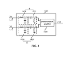
- FIG. 4 shows an alternative implementation of the subtractor 1421 of the second calculating unit 142 according to an embodiment of the invention.
- the subtractor 1421 includes a first modifying unit A, a second modifying unit B, and an instrumentation amplifier 1428.
- the first modifying unit A includes a low pass filter 1424 and a high pass filter 1425.
- the second modifying unit B includes a low pass filter 1426 and a high pass filter 1427.
- the first modifying unit A is coupled to transmission wire L1-1 for receiving the first input signal V1, and generating a first modified signal.
- the second modifying unit B is coupled to transmission wire L1-2 for receiving the second input signal V2, and generating a second modified signal.
- the instrumentation amplifier 1428 is coupled to the first modifying unit A and the second modifying unit B for receiving the first modified signal and the second modified signal so as to generate the first difference signal ⁇ M1.
- the subtractor 1441 of the third calculating unit 144 may be implemented using similar circuits as shown in FIG. 4 .
- the first input signal V1 is filtered by the low pass filter 1424 and the high pass filter 1425 sequentially
- the second input signal V2 is filtered by the low pass filter 1426 and the high pass filter 1427 sequentially.
- the frequency response of the low pass filter 1424 and that of the low pass filter 1426 shall be different.
- the cut-off frequencies of the low pass filter 1424 may be 30Hz
- the cut-off frequencies of the low pass filter 1426 may be 97kHz.
- the frequency response of the high pass filter 1425 and that of the high pass filter 1427 shall be different.
- the cut-off frequencies of the high pass filter 1425 may be 1Hz
- the cut-off frequencies of the high pass filter 1427 may be 0.015Hz.
- the first input signal V1 and second input signal V2 are modified by different modifying process so as to increase the discrimination of the first input signal V1 and the second input signal V2.
- the third input signal V3 and fourth input signal V4 may be modified by different modifying process so as to increase the discrimination of the third input signal V3 and the fourth input signal V4.
- FIG. 5A shows an oscillogram of the body electrical signal according to an embodiment of the invention.
- the body electrical signal generated by the first calculating unit 140 is severely interfered with the noise, such as motion artifacts, respiration, or electrode noise.
- doctors may not be able to correctly analyze the waveform shape between successive beats of the body electrical signal, and may misdiagnose the level of cardiac stability accordingly.
- FIG. 5B shows an oscillogram of motion artifacts within the body electrical signal according to an embodiment of the invention.
- the second calculating unit 142 and the third calculating unit 144 can estimate the motion artifacts around the first electrode group 10 and the second electrode group 12.
- FIG. 5C shows an oscillogram of the lead signal according to an embodiment of the invention.
- the fourth calculating unit 146 eliminates the estimated noise shown in FIG. 5B from the body electrical signal shown in FIG. 5A to generate the lead signal shown in FIG. 5C .
- the signal analyzing system 1 can greatly reduce the motion artifacts by utilizing the disclosed first electrode group 10, the second electrode group 12, and processing module 14.
- each electrode group may have more than two electrodes, and can obtain more than two input signals correspondingly.
- FIG. 6 shows a schematic diagram of the first electrode group according to another embodiment of the invention.
- the electrode group 10a can have 4 electrodes, such as an electrode 102a, an electrode 104a, an electrode 106a and an electrode 108a.
- the distance between the electrode 102a and the electrode 104a is denoted as distance d3.
- the distance between the electrode 102a and the electrode 106a is denoted as distance d4.
- the distance between the electrode 102a and the electrode 108a is denoted as distance d5.
- all of the distance d3, d4, and d5 may be less than the first predetermined distance, e.g. 1cm or 1.5cm.
- FIG. 7 shows an example flow chart of a signal analyzing method according to an embodiment of the invention.
- the first calculating unit 140 generates a body electrical signal according to one of input signals transmitted through the transmission line L1 and one of input signals transmitted through the transmission line L2.
- the second calculating unit 142 generates a first filtered signal for estimating the motion artifact around the first electrode group 10 by filtering the difference of the input signals obtained from the first electrode group 10.
- step S34 the third calculating unit 144 generates a second filtered signal for estimating the motion artifact around the second electrode group 12 by filtering the difference of the input signals obtained from the second electrode group 12.
- step S36 the fourth calculating unit 146 generates the lead signal by subtracting the first filtered signal and the second filtered signal from the body electrical signal.
- the embodiments of the invention disclose a method and a system for signal analyzing with a processing module which can reduce the noise components, especially motion artifacts, of the ECG signal.
- One of the advantages of the approach is that users can easily and correctly analyze the waveform shape between successive beats in the filtered ECG signal, and can avoid misdiagnosing the level of cardiac stability.
Landscapes
- Health & Medical Sciences (AREA)
- Life Sciences & Earth Sciences (AREA)
- Engineering & Computer Science (AREA)
- Molecular Biology (AREA)
- Animal Behavior & Ethology (AREA)
- Pathology (AREA)
- Physics & Mathematics (AREA)
- Biomedical Technology (AREA)
- Heart & Thoracic Surgery (AREA)
- Medical Informatics (AREA)
- Veterinary Medicine (AREA)
- Surgery (AREA)
- Biophysics (AREA)
- General Health & Medical Sciences (AREA)
- Public Health (AREA)
- Cardiology (AREA)
- Signal Processing (AREA)
- Artificial Intelligence (AREA)
- Computer Vision & Pattern Recognition (AREA)
- Physiology (AREA)
- Psychiatry (AREA)
- Measurement And Recording Of Electrical Phenomena And Electrical Characteristics Of The Living Body (AREA)
Applications Claiming Priority (1)
| Application Number | Priority Date | Filing Date | Title |
|---|---|---|---|
| US13/873,202 US9687164B2 (en) | 2013-04-29 | 2013-04-29 | Method and system for signal analyzing and processing module |
Publications (2)
| Publication Number | Publication Date |
|---|---|
| EP2799005A1 true EP2799005A1 (de) | 2014-11-05 |
| EP2799005B1 EP2799005B1 (de) | 2017-10-04 |
Family
ID=48670317
Family Applications (1)
| Application Number | Title | Priority Date | Filing Date |
|---|---|---|---|
| EP13002845.9A Active EP2799005B1 (de) | 2013-04-29 | 2013-06-03 | Verfahren und System zur Signalanalyse und Verarbeitungsmodul |
Country Status (3)
| Country | Link |
|---|---|
| US (1) | US9687164B2 (de) |
| EP (1) | EP2799005B1 (de) |
| CN (1) | CN104116508B (de) |
Citations (2)
| Publication number | Priority date | Publication date | Assignee | Title |
|---|---|---|---|---|
| US4627441A (en) * | 1984-04-27 | 1986-12-09 | Medtronic, Inc. | B medical monitoring circuit |
| US20080069375A1 (en) * | 2006-09-15 | 2008-03-20 | Lange Daniel H | Cancellation of contact artifacts in a differential electrophysiological signal |
Family Cites Families (16)
| Publication number | Priority date | Publication date | Assignee | Title |
|---|---|---|---|---|
| US4799493A (en) * | 1987-03-13 | 1989-01-24 | Cardiac Pacemakers, Inc. | Dual channel coherent fibrillation detection system |
| US5713367A (en) * | 1994-01-26 | 1998-02-03 | Cambridge Heart, Inc. | Measuring and assessing cardiac electrical stability |
| US5671752A (en) * | 1995-03-31 | 1997-09-30 | Universite De Montreal/The Royal Insitution For The Advancement Of Learning (Mcgill University) | Diaphragm electromyography analysis method and system |
| WO2002056818A2 (en) * | 2001-01-16 | 2002-07-25 | Universite De Montreal | Myoelectrically activated respiratory leak sealing |
| US6547746B1 (en) * | 2001-08-27 | 2003-04-15 | Andrew A. Marino | Method and apparatus for determining response thresholds |
| GB0123772D0 (en) * | 2001-10-03 | 2001-11-21 | Qinetiq Ltd | Apparatus for monitoring fetal heartbeat |
| US20070156190A1 (en) * | 2005-12-30 | 2007-07-05 | Can Cinbis | Subcutaneous ICD with motion artifact noise suppression |
| US20070213626A1 (en) * | 2006-03-10 | 2007-09-13 | Michael Sasha John | Baseline correction in systems for detecting ischemia |
| US8200317B2 (en) * | 2006-06-30 | 2012-06-12 | Intel Corporation | Method and apparatus for amplifying multiple signals using a single multiplexed amplifier channel with software controlled AC response |
| RU2009105130A (ru) * | 2006-07-14 | 2010-08-27 | Конинклейке Филипс Электроникс Н.В. (Nl) | Устройство, система и способ мониторинга сердечных сокращений |
| DE102006038809A1 (de) * | 2006-08-18 | 2008-02-21 | Basf Construction Polymers Gmbh | Wasserlösliche und biologisch abbaubare Copolymere auf Polyamidbasis und deren Verwendung |
| WO2010003175A1 (en) * | 2008-07-07 | 2010-01-14 | Heard Systems Pty Ltd | A system for sensing electrophysiological signals |
| US8706464B2 (en) * | 2010-01-31 | 2014-04-22 | Vladimir Shusterman | Health data dynamics, its sources and linkage with genetic/molecular tests |
| US8364255B2 (en) * | 2010-03-10 | 2013-01-29 | Brainscope Company, Inc. | Method and device for removing EEG artifacts |
| FI20106337A0 (fi) * | 2010-12-17 | 2010-12-17 | Polar Electro Oy | Häiriönvaimennuspiiri biometrisiä mittauksia varten |
| CN102389303A (zh) * | 2011-08-02 | 2012-03-28 | 长春华讯信息科技有限公司 | 一种心电监护方法及装置 |
-
2013
- 2013-04-29 US US13/873,202 patent/US9687164B2/en active Active
- 2013-06-03 EP EP13002845.9A patent/EP2799005B1/de active Active
- 2013-07-31 CN CN201310329152.1A patent/CN104116508B/zh active Active
Patent Citations (2)
| Publication number | Priority date | Publication date | Assignee | Title |
|---|---|---|---|---|
| US4627441A (en) * | 1984-04-27 | 1986-12-09 | Medtronic, Inc. | B medical monitoring circuit |
| US20080069375A1 (en) * | 2006-09-15 | 2008-03-20 | Lange Daniel H | Cancellation of contact artifacts in a differential electrophysiological signal |
Non-Patent Citations (2)
| Title |
|---|
| ALMENAR V ET AL: "A new adaptive scheme for ECG enhancement", SIGNAL PROCESSING, ELSEVIER SCIENCE PUBLISHERS B.V. AMSTERDAM, NL, vol. 75, no. 3, 1 June 1999 (1999-06-01), pages 253 - 263, XP004166444, ISSN: 0165-1684, DOI: 10.1016/S0165-1684(98)00237-0 * |
| JEONG-WHAN LEE ET AL: "Reusable Electrical Activity of the Heart Monitoring Patch for Mobile/Ubiquitous Healthcare", JOURNAL OF MEDICAL SYSTEMS, KLUWER ACADEMIC PUBLISHERS-PLENUM PUBLISHERS, NE, vol. 33, no. 1, 25 June 2008 (2008-06-25), pages 41 - 46, XP019681707, ISSN: 1573-689X * |
Also Published As
| Publication number | Publication date |
|---|---|
| CN104116508B (zh) | 2016-03-02 |
| US9687164B2 (en) | 2017-06-27 |
| EP2799005B1 (de) | 2017-10-04 |
| US20140323890A1 (en) | 2014-10-30 |
| CN104116508A (zh) | 2014-10-29 |
Similar Documents
| Publication | Publication Date | Title |
|---|---|---|
| Luo et al. | A review of electrocardiogram filtering | |
| Limaye et al. | ECG noise sources and various noise removal techniques: A survey | |
| Serteyn et al. | Motion artifacts in capacitive ECG measurements: Reducing the combined effect of DC voltages and capacitance changes using an injection signal | |
| Kadam et al. | Reduction of power line interference in ECG signal using FIR filter | |
| TWI481196B (zh) | 生物電信號感測儀器與其基線漂移移除裝置 | |
| JP2009509711A (ja) | Ecg信号からベースラインふらつきを除去するための方法、および装置 | |
| US12028103B1 (en) | Physiological signal acquisition system and method with improved noise and common mode rejection performance and signal quality | |
| US10117591B2 (en) | Impedance bootstrap circuit for an interface of a monitoring device | |
| Nayak et al. | Filtering techniques for ECG signal processing | |
| Chavan et al. | Design and implementation of digital FIR equiripple notch filter on ECG signal for removal of power line interference | |
| EP2724666A1 (de) | Vorrichtung und Verfahren zur Messung von Biosignalen | |
| US11147517B2 (en) | Physiological measurement device with common mode interference suppression | |
| KR20150017928A (ko) | 공통모드에 의한 차폐 구동을 통해 생체 신호를 측정하는 방법, 장치 및 회로 | |
| Wang et al. | Design and evaluation of a novel wireless reconstructed 3-lead ECG monitoring system | |
| CN114222524B (zh) | 用于处理呼吸速率的系统 | |
| CN105790729B (zh) | 使用线性调频z变换和自适应滤波的工频滤波方法和装置 | |
| Niederhauser et al. | A baseline wander tracking system for artifact rejection in long-term electrocardiography | |
| CN107890347A (zh) | 滤除工频干扰信号的控制方法及系统 | |
| Gowri et al. | An efficient variable step size least mean square adaptive algorithm used to enhance the quality of electrocardiogram signal | |
| EP2799005B1 (de) | Verfahren und System zur Signalanalyse und Verarbeitungsmodul | |
| Bhoi et al. | Wavelet packet based Denoising of EMG Signal | |
| Maniam et al. | Biosensor Interface Controller for Chronic Kidney Disease Monitoring Using Internet of Things (IoT) | |
| Abdul Jamil et al. | Electrocardiograph (ECG) circuit design and software-based processing using LabVIEW | |
| CN106037718B (zh) | 可穿戴心电图系统 | |
| Ghasemi | Ecg noise cancellation using kernel adaptive filtering |
Legal Events
| Date | Code | Title | Description |
|---|---|---|---|
| PUAI | Public reference made under article 153(3) epc to a published international application that has entered the european phase |
Free format text: ORIGINAL CODE: 0009012 |
|
| 17P | Request for examination filed |
Effective date: 20130603 |
|
| AK | Designated contracting states |
Kind code of ref document: A1 Designated state(s): AL AT BE BG CH CY CZ DE DK EE ES FI FR GB GR HR HU IE IS IT LI LT LU LV MC MK MT NL NO PL PT RO RS SE SI SK SM TR |
|
| AX | Request for extension of the european patent |
Extension state: BA ME |
|
| R17P | Request for examination filed (corrected) |
Effective date: 20150504 |
|
| RBV | Designated contracting states (corrected) |
Designated state(s): AL AT BE BG CH CY CZ DE DK EE ES FI FR GB GR HR HU IE IS IT LI LT LU LV MC MK MT NL NO PL PT RO RS SE SI SK SM TR |
|
| REG | Reference to a national code |
Ref country code: DE Ref legal event code: R079 Ref document number: 602013027363 Country of ref document: DE Free format text: PREVIOUS MAIN CLASS: A61B0005000000 Ipc: A61B0005040000 |
|
| GRAP | Despatch of communication of intention to grant a patent |
Free format text: ORIGINAL CODE: EPIDOSNIGR1 |
|
| RIC1 | Information provided on ipc code assigned before grant |
Ipc: A61B 5/00 20060101ALI20170614BHEP Ipc: A61B 5/04 20060101AFI20170614BHEP Ipc: A61B 5/0428 20060101ALI20170614BHEP |
|
| INTG | Intention to grant announced |
Effective date: 20170705 |
|
| GRAA | (expected) grant |
Free format text: ORIGINAL CODE: 0009210 |
|
| GRAS | Grant fee paid |
Free format text: ORIGINAL CODE: EPIDOSNIGR3 |
|
| AK | Designated contracting states |
Kind code of ref document: B1 Designated state(s): AL AT BE BG CH CY CZ DE DK EE ES FI FR GB GR HR HU IE IS IT LI LT LU LV MC MK MT NL NO PL PT RO RS SE SI SK SM TR |
|
| REG | Reference to a national code |
Ref country code: GB Ref legal event code: FG4D |
|
| REG | Reference to a national code |
Ref country code: CH Ref legal event code: EP |
|
| REG | Reference to a national code |
Ref country code: AT Ref legal event code: REF Ref document number: 933236 Country of ref document: AT Kind code of ref document: T Effective date: 20171015 |
|
| REG | Reference to a national code |
Ref country code: IE Ref legal event code: FG4D |
|
| REG | Reference to a national code |
Ref country code: DE Ref legal event code: R096 Ref document number: 602013027363 Country of ref document: DE |
|
| REG | Reference to a national code |
Ref country code: NL Ref legal event code: MP Effective date: 20171004 |
|
| REG | Reference to a national code |
Ref country code: LT Ref legal event code: MG4D |
|
| REG | Reference to a national code |
Ref country code: AT Ref legal event code: MK05 Ref document number: 933236 Country of ref document: AT Kind code of ref document: T Effective date: 20171004 |
|
| PG25 | Lapsed in a contracting state [announced via postgrant information from national office to epo] |
Ref country code: NL Free format text: LAPSE BECAUSE OF FAILURE TO SUBMIT A TRANSLATION OF THE DESCRIPTION OR TO PAY THE FEE WITHIN THE PRESCRIBED TIME-LIMIT Effective date: 20171004 |
|
| PG25 | Lapsed in a contracting state [announced via postgrant information from national office to epo] |
Ref country code: NO Free format text: LAPSE BECAUSE OF FAILURE TO SUBMIT A TRANSLATION OF THE DESCRIPTION OR TO PAY THE FEE WITHIN THE PRESCRIBED TIME-LIMIT Effective date: 20180104 Ref country code: FI Free format text: LAPSE BECAUSE OF FAILURE TO SUBMIT A TRANSLATION OF THE DESCRIPTION OR TO PAY THE FEE WITHIN THE PRESCRIBED TIME-LIMIT Effective date: 20171004 Ref country code: LT Free format text: LAPSE BECAUSE OF FAILURE TO SUBMIT A TRANSLATION OF THE DESCRIPTION OR TO PAY THE FEE WITHIN THE PRESCRIBED TIME-LIMIT Effective date: 20171004 Ref country code: ES Free format text: LAPSE BECAUSE OF FAILURE TO SUBMIT A TRANSLATION OF THE DESCRIPTION OR TO PAY THE FEE WITHIN THE PRESCRIBED TIME-LIMIT Effective date: 20171004 Ref country code: SE Free format text: LAPSE BECAUSE OF FAILURE TO SUBMIT A TRANSLATION OF THE DESCRIPTION OR TO PAY THE FEE WITHIN THE PRESCRIBED TIME-LIMIT Effective date: 20171004 |
|
| PG25 | Lapsed in a contracting state [announced via postgrant information from national office to epo] |
Ref country code: RS Free format text: LAPSE BECAUSE OF FAILURE TO SUBMIT A TRANSLATION OF THE DESCRIPTION OR TO PAY THE FEE WITHIN THE PRESCRIBED TIME-LIMIT Effective date: 20171004 Ref country code: BG Free format text: LAPSE BECAUSE OF FAILURE TO SUBMIT A TRANSLATION OF THE DESCRIPTION OR TO PAY THE FEE WITHIN THE PRESCRIBED TIME-LIMIT Effective date: 20180104 Ref country code: AT Free format text: LAPSE BECAUSE OF FAILURE TO SUBMIT A TRANSLATION OF THE DESCRIPTION OR TO PAY THE FEE WITHIN THE PRESCRIBED TIME-LIMIT Effective date: 20171004 Ref country code: IS Free format text: LAPSE BECAUSE OF FAILURE TO SUBMIT A TRANSLATION OF THE DESCRIPTION OR TO PAY THE FEE WITHIN THE PRESCRIBED TIME-LIMIT Effective date: 20180204 Ref country code: LV Free format text: LAPSE BECAUSE OF FAILURE TO SUBMIT A TRANSLATION OF THE DESCRIPTION OR TO PAY THE FEE WITHIN THE PRESCRIBED TIME-LIMIT Effective date: 20171004 Ref country code: GR Free format text: LAPSE BECAUSE OF FAILURE TO SUBMIT A TRANSLATION OF THE DESCRIPTION OR TO PAY THE FEE WITHIN THE PRESCRIBED TIME-LIMIT Effective date: 20180105 Ref country code: HR Free format text: LAPSE BECAUSE OF FAILURE TO SUBMIT A TRANSLATION OF THE DESCRIPTION OR TO PAY THE FEE WITHIN THE PRESCRIBED TIME-LIMIT Effective date: 20171004 |
|
| REG | Reference to a national code |
Ref country code: FR Ref legal event code: PLFP Year of fee payment: 6 |
|
| REG | Reference to a national code |
Ref country code: DE Ref legal event code: R097 Ref document number: 602013027363 Country of ref document: DE |
|
| PG25 | Lapsed in a contracting state [announced via postgrant information from national office to epo] |
Ref country code: CZ Free format text: LAPSE BECAUSE OF FAILURE TO SUBMIT A TRANSLATION OF THE DESCRIPTION OR TO PAY THE FEE WITHIN THE PRESCRIBED TIME-LIMIT Effective date: 20171004 Ref country code: SK Free format text: LAPSE BECAUSE OF FAILURE TO SUBMIT A TRANSLATION OF THE DESCRIPTION OR TO PAY THE FEE WITHIN THE PRESCRIBED TIME-LIMIT Effective date: 20171004 Ref country code: DK Free format text: LAPSE BECAUSE OF FAILURE TO SUBMIT A TRANSLATION OF THE DESCRIPTION OR TO PAY THE FEE WITHIN THE PRESCRIBED TIME-LIMIT Effective date: 20171004 Ref country code: EE Free format text: LAPSE BECAUSE OF FAILURE TO SUBMIT A TRANSLATION OF THE DESCRIPTION OR TO PAY THE FEE WITHIN THE PRESCRIBED TIME-LIMIT Effective date: 20171004 |
|
| PLBE | No opposition filed within time limit |
Free format text: ORIGINAL CODE: 0009261 |
|
| STAA | Information on the status of an ep patent application or granted ep patent |
Free format text: STATUS: NO OPPOSITION FILED WITHIN TIME LIMIT |
|
| PG25 | Lapsed in a contracting state [announced via postgrant information from national office to epo] |
Ref country code: RO Free format text: LAPSE BECAUSE OF FAILURE TO SUBMIT A TRANSLATION OF THE DESCRIPTION OR TO PAY THE FEE WITHIN THE PRESCRIBED TIME-LIMIT Effective date: 20171004 Ref country code: IT Free format text: LAPSE BECAUSE OF FAILURE TO SUBMIT A TRANSLATION OF THE DESCRIPTION OR TO PAY THE FEE WITHIN THE PRESCRIBED TIME-LIMIT Effective date: 20171004 Ref country code: SM Free format text: LAPSE BECAUSE OF FAILURE TO SUBMIT A TRANSLATION OF THE DESCRIPTION OR TO PAY THE FEE WITHIN THE PRESCRIBED TIME-LIMIT Effective date: 20171004 Ref country code: PL Free format text: LAPSE BECAUSE OF FAILURE TO SUBMIT A TRANSLATION OF THE DESCRIPTION OR TO PAY THE FEE WITHIN THE PRESCRIBED TIME-LIMIT Effective date: 20171004 |
|
| 26N | No opposition filed |
Effective date: 20180705 |
|
| PG25 | Lapsed in a contracting state [announced via postgrant information from national office to epo] |
Ref country code: SI Free format text: LAPSE BECAUSE OF FAILURE TO SUBMIT A TRANSLATION OF THE DESCRIPTION OR TO PAY THE FEE WITHIN THE PRESCRIBED TIME-LIMIT Effective date: 20171004 |
|
| REG | Reference to a national code |
Ref country code: CH Ref legal event code: PL |
|
| REG | Reference to a national code |
Ref country code: BE Ref legal event code: MM Effective date: 20180630 |
|
| REG | Reference to a national code |
Ref country code: IE Ref legal event code: MM4A |
|
| PG25 | Lapsed in a contracting state [announced via postgrant information from national office to epo] |
Ref country code: LU Free format text: LAPSE BECAUSE OF NON-PAYMENT OF DUE FEES Effective date: 20180603 Ref country code: MC Free format text: LAPSE BECAUSE OF FAILURE TO SUBMIT A TRANSLATION OF THE DESCRIPTION OR TO PAY THE FEE WITHIN THE PRESCRIBED TIME-LIMIT Effective date: 20171004 |
|
| PG25 | Lapsed in a contracting state [announced via postgrant information from national office to epo] |
Ref country code: LI Free format text: LAPSE BECAUSE OF NON-PAYMENT OF DUE FEES Effective date: 20180630 Ref country code: CH Free format text: LAPSE BECAUSE OF NON-PAYMENT OF DUE FEES Effective date: 20180630 Ref country code: IE Free format text: LAPSE BECAUSE OF NON-PAYMENT OF DUE FEES Effective date: 20180603 |
|
| PG25 | Lapsed in a contracting state [announced via postgrant information from national office to epo] |
Ref country code: BE Free format text: LAPSE BECAUSE OF NON-PAYMENT OF DUE FEES Effective date: 20180630 |
|
| PG25 | Lapsed in a contracting state [announced via postgrant information from national office to epo] |
Ref country code: MT Free format text: LAPSE BECAUSE OF NON-PAYMENT OF DUE FEES Effective date: 20180603 |
|
| PG25 | Lapsed in a contracting state [announced via postgrant information from national office to epo] |
Ref country code: TR Free format text: LAPSE BECAUSE OF FAILURE TO SUBMIT A TRANSLATION OF THE DESCRIPTION OR TO PAY THE FEE WITHIN THE PRESCRIBED TIME-LIMIT Effective date: 20171004 |
|
| PG25 | Lapsed in a contracting state [announced via postgrant information from national office to epo] |
Ref country code: HU Free format text: LAPSE BECAUSE OF FAILURE TO SUBMIT A TRANSLATION OF THE DESCRIPTION OR TO PAY THE FEE WITHIN THE PRESCRIBED TIME-LIMIT; INVALID AB INITIO Effective date: 20130603 Ref country code: PT Free format text: LAPSE BECAUSE OF FAILURE TO SUBMIT A TRANSLATION OF THE DESCRIPTION OR TO PAY THE FEE WITHIN THE PRESCRIBED TIME-LIMIT Effective date: 20171004 |
|
| PG25 | Lapsed in a contracting state [announced via postgrant information from national office to epo] |
Ref country code: MK Free format text: LAPSE BECAUSE OF NON-PAYMENT OF DUE FEES Effective date: 20171004 Ref country code: CY Free format text: LAPSE BECAUSE OF FAILURE TO SUBMIT A TRANSLATION OF THE DESCRIPTION OR TO PAY THE FEE WITHIN THE PRESCRIBED TIME-LIMIT Effective date: 20171004 |
|
| PG25 | Lapsed in a contracting state [announced via postgrant information from national office to epo] |
Ref country code: AL Free format text: LAPSE BECAUSE OF FAILURE TO SUBMIT A TRANSLATION OF THE DESCRIPTION OR TO PAY THE FEE WITHIN THE PRESCRIBED TIME-LIMIT Effective date: 20171004 |
|
| REG | Reference to a national code |
Ref country code: DE Ref legal event code: R079 Ref document number: 602013027363 Country of ref document: DE Free format text: PREVIOUS MAIN CLASS: A61B0005040000 Ipc: A61B0005240000 |
|
| P01 | Opt-out of the competence of the unified patent court (upc) registered |
Effective date: 20230607 |
|
| PGFP | Annual fee paid to national office [announced via postgrant information from national office to epo] |
Ref country code: DE Payment date: 20250429 Year of fee payment: 13 |
|
| PGFP | Annual fee paid to national office [announced via postgrant information from national office to epo] |
Ref country code: GB Payment date: 20250425 Year of fee payment: 13 |
|
| PGFP | Annual fee paid to national office [announced via postgrant information from national office to epo] |
Ref country code: FR Payment date: 20250508 Year of fee payment: 13 |