EP2799110A1 - Procédé destiné au fonctionnement d'un appareil de bio-résonance - Google Patents
Procédé destiné au fonctionnement d'un appareil de bio-résonance Download PDFInfo
- Publication number
- EP2799110A1 EP2799110A1 EP14001541.3A EP14001541A EP2799110A1 EP 2799110 A1 EP2799110 A1 EP 2799110A1 EP 14001541 A EP14001541 A EP 14001541A EP 2799110 A1 EP2799110 A1 EP 2799110A1
- Authority
- EP
- European Patent Office
- Prior art keywords
- frequencies
- patient
- frequency
- data points
- value
- Prior art date
- Legal status (The legal status is an assumption and is not a legal conclusion. Google has not performed a legal analysis and makes no representation as to the accuracy of the status listed.)
- Granted
Links
Images




Classifications
-
- A—HUMAN NECESSITIES
- A61—MEDICAL OR VETERINARY SCIENCE; HYGIENE
- A61N—ELECTROTHERAPY; MAGNETOTHERAPY; RADIATION THERAPY; ULTRASOUND THERAPY
- A61N1/00—Electrotherapy; Circuits therefor
- A61N1/18—Applying electric currents by contact electrodes
- A61N1/32—Applying electric currents by contact electrodes alternating or intermittent currents
-
- A—HUMAN NECESSITIES
- A61—MEDICAL OR VETERINARY SCIENCE; HYGIENE
- A61N—ELECTROTHERAPY; MAGNETOTHERAPY; RADIATION THERAPY; ULTRASOUND THERAPY
- A61N1/00—Electrotherapy; Circuits therefor
- A61N1/40—Applying electric fields by inductive or capacitive coupling ; Applying radio-frequency signals
Definitions
- the invention relates to a method for operating a medical device, in particular a bioresonance device.
- the application takes the priority of the German patent application 10 2013 007 448.7 to which reference is made to the content.
- the method and the device according to the invention are used to determine data concerning the physiological condition of an animal or human patient and their evaluation with regard to the physiological state and the possible therapy of the patient.
- bioresonance has become increasingly important as a diagnostic and / or treatment method of alternative medicine.
- the basis of bioresonance therapy is the search (analysis) and administration (therapy) of frequencies and frequency spectra with the aim of restarting self-regulation in humans and animals.
- the human or animal body radiates different electromagnetic oscillations.
- Cells, tissues and organs each have specific vibrations. These individual vibrations are connected and influence each other. Together they form the overall vibration spectrum of the patient, the individual vibration pattern.
- a detector is brought into contact with the patient who receives the electromagnetic oscillations of the patient, or individual body parts or organs and transmits it to the bioresonance device.
- the bioresonance device Depending on the vibrations received, the bioresonance device generates electromagnetic frequencies that are relayed to the patient (i.e., "impressed"). This achieves the therapeutic goal.
- the devices known from the prior art generally use the measurement of the skin resistance of the patient. Since the skin resistance varies greatly as a result of numerous influences such as skin condition, blood circulation, ambient temperature or water content in the body, this measurement method is only limited use, since it can easily lead to incorrect measurement results. Thus, this method can not sufficiently ensure that the individual vibration pattern of the patient and the patient's response to the therapeutic vibration (biofeedback) are actually recorded correctly. This uncertainty has a negative effect on the success of therapy and the validity of the diagnosis.
- the object of the invention is to provide a contrast improved system for the application of bioresonance diagnostics and therapy and a method for operating this system.
- the invention is based on the finding that a human or animal organism reacts physiologically on a stimulus in the form of an ("impressed") electromagnetic frequency acting on it and the sum of possible different reactions can be recognized as a change in an electrophysiological signal of the organism.
- the change in the electrophysiological signal is measurable.
- the change in the electrophysiological measured value is particularly noticeable in the case of different stimuli, in this case frequencies. Accordingly, the reaction pattern detected as a function of different frequencies can be used from electrophysiological measured values of the organism for the diagnosis of disease or stress states of the organism.
- the individual resonant frequency patterns created using the method according to the invention can also be used for therapeutic purposes.
- frequencies are impressed on the patient, which counteract the disturbance condition and thus bring the patient as far as possible back to its normal physiological state (i.e., healthy state).
- electrophysiological measured values are first of all collected by the patient, as stated. These measurements are preferably results of a method selected from the group of the following methods: Electroencephalography (EEG), electrocardiography (ECG), electrogastrography, electrocochleography, electronystagmography, electrooculography, electroretinography, electromyography, and electroneurography. Preference is given to measured values from electroencephalography and electrocardiography.
- the method according to the invention is particularly preferably carried out with measured values from electrocardiography.
- the electrical activity ie the conduction of an electrical pulse or an excitation
- an organ or tissue is detected.
- This activity is measured over time and recorded in curves that are typical for the respective procedure.
- the measured values relevant to the invention are therefore represented as measured value curves.
- the shape of the respective curve for example the position and steepness of certain peaks, gives the medical expert indications about the physiological state of the respective organ or tissue.
- a heartbeat is displayed in a typical curve known as the PQRSTU curve.
- the individual letters are names for characteristic peaks, valleys or other typical features of the curve (see also Fig. 1A ).
- the electrophysiological measured values ascertained by the patient are preferably not used directly (that is to say in the sense of raw data) for comparison with standard values or standard curves, but are first of all computationally processed ("calculated data point").
- the area under an area under the curve is detected and used as a starting point for comparison with a standard value.
- a meaningful curve section is first defined for the respective method. For example, with an ECG as a curve section, preferably a complete P-Q-R-S-T-U curve, i.
- the respective area is thus determined under a P-Q-R-S-T-U curve measured at a specific frequency as the preferred electrophysiological data point.
- a specific frequency as the preferred electrophysiological data point.
- at least two or more such data points are detected, i. it is determined a plurality of areas.
- the curves are recorded as a function of simultaneously impressed frequencies.
- one or more of the cardiovascular measured values can also be selected from the group comprising heart rate, heart rhythm, length, amplitude or shape of the P-wave, the T-wave, the U-wave or the QRS complex, length of the PQ interval, the QT interval, the RR interval or the ST segment.
- the heart rate in particular the heart rate variability (HRV), is particularly preferably used. This can be determined based on three to four heartbeats. A control based on 3-4 heart beats is advantageous because the HRV reacts only briefly to the frequencies impressed from the outside and adapts to the new situation again after a maximum of 3-4 heart beats.
- the electrophysiological measured values of the patient are detected by the method according to the invention as a function of electromagnetic vibrations (frequencies) impressed on the patient. This means that the readings are taken while the patient is reading the electrical pulses, i. the stimulation through which impressed frequencies receives.
- step a) of the method according to the invention is implemented.
- the patient is thus simultaneously connected to a device for recording the electrophysiological measured values and to a device for imparting (stimulating) the frequencies to the patient. Both devices can be separate or combined.
- At least two, in particular more than two, frequencies are impressed on the patient in a first step.
- the more than two frequencies are imposed as a sequence of single frequencies, i. the frequencies act on the patient in succession rather than as a mixture of different frequencies.
- the effect of a specific single frequency on the patient can be determined.
- between 10 and 500, preferably between 50 and 400, more preferably between 100 and 200 frequencies are embossed onto the patient. This then results in a so-called range value measurement. At each of these frequencies an electrophysiological measurement curve is recorded. At N impressed frequencies thus also N electrophysiological measured value curves are recorded.
- the impressed frequencies are preferably in the range of 0.1 Hz to 10.0 GHz. In a preferred embodiment, they are in the range of 0.1 Hz to 100 MHz and preferably in the range of 0.1 Hz to 500 MHz.
- the frequencies are sequential, i. in a sequence, they may have the same frequency difference to each other, i. the frequency sequence has a uniform step size. For example, if a sequence of frequencies with a frequency value of 0.5 kHz; 1.0 kHz; 1.5 kHz; 2.0 kHz; 2.5 kHz; 3.0 kHz; 3.5 kHz; 4.0 kHz, etc., the step size is 0.5 kHz.
- individual frequencies are impressed on the patient. It is preferred, however, to impose frequency spectra, i. to apply several single frequencies simultaneously to the patient.
- the impressed spectra are decadal frequency spectra, i. Spectra, each starting from a single frequency as the fundamental frequency, and then only have other frequencies, which are each increased by a factor of 10 against the respective low frequency.
- the lowest frequency value is referred to as the "frequency baseline".
- the decadic frequency spectrum would include frequencies of 5 kHz, 50 kHz, 500 kHz, and so on.
- a decadal frequency spectrum contains only those frequencies that differ by a factor of 10 from each other.
- the basic frequency value is not for a specific single frequency, but for the smallest value of a frequency spectrum, wherein the other frequencies each have a higher frequency by a factor of 10 n .
- the general term frequency is understood to mean both the single frequency and a frequency spectrum.
- the lowest frequency is impressed. Then the frequency range is progressively stepped through to the highest frequency. But the sequence can also be the other way round, i. E. It can also be started with the highest frequency and then a gradual reduction to the smallest frequency.
- the electrophysiological data points are compared with a standard value for these data points so as to determine at least one resonance frequency.
- the resonance frequency is the frequency whose electrophysiological data point deviates from the standard value.
- two or more resonance frequencies can be found. Often the number of identified Resonant frequencies between 10 and 100, preferably between 50 and 80 resonant frequencies. The number of resonant frequencies determined in a range value measurement can be influenced by the use of a filter.
- the default value can be a value from an external database, i. a value that does not go back to the individual patient.
- the typical curves of the electrophysiological measured values according to the invention are fundamentally known to the person skilled in the art.
- the curve obtained by the patient at a certain frequency can be compared to such a typical curve.
- the analysis of the area under the curve can preferably serve this purpose.
- a standard value is used, which is determined in the respective range value measurement of the patient.
- the use of the mean value from the patient's own range value measurement as desired value has the advantage that it reflects the individual electrophysiologically detectable state of the patient at the time of the measurement.
- the patient's own, i. individual, default value is preferably the mean of all data points determined for the patient in the course of a measurement. This default value can also be called a setpoint. Also for this calculation, the area under the measured value curve is preferably used. Those frequencies at which the area of the measured value curve deviates from the mean value of all detected areas then represent the resonance frequencies sought. The degree of deviation, which is considered to be diagnostically or therapeutically relevant, can be determined by a person skilled in the art. Determining the resonance frequencies creates an individual "energetic fingerprint" of the patient.
- the measured value is increased or decreased by the impressed frequency.
- This effect is expressed by the so-called polarity of the resonance frequency ("+" for increase; "-" for reduction).
- the resonant frequency patterns from the database preferably represent certain physiological conditions.
- the databases are based on a high number of different range value measurements of different patients.
- the databases to be used according to the invention thus represent standard resonance frequency patterns.
- resonance patterns are preferably both for a healthy normal state and for pathological conditions filed.
- the database comprises more than 500, preferably more than 1500 standard frequency patterns.
- the resonance frequencies determined by the method according to the invention are used to select therapeutically effective frequencies for this patient.
- the selection can be made manually by the therapist or automated by the device, in particular by a bioresonance device.
- the selection of frequencies advantageously follows the principle of "similia similibus currentur", i. the patient is given identical or similar frequencies for therapy ("harmonization") of his disorder.
- the inventive method for operating the medical device can be designed as a control loop by the default value as setpoint and the data points collected after step a) represent the actual value.
- the resonance frequencies generated and transmitted after steps e) and f) can be impressed on the patient and his electrophysiological data points according to step a) in dependence thereon Frequencies are determined. The method according to the invention is then repeated iteratively until there is no medically relevant deviation between the actual values and the desired value.
- the inventors have found that the targeted control of a bioresonance device can be carried out in a very advantageous manner by the detection and evaluation of cardiovascular measured values.
- this embodiment according to the invention has the advantage that cardiovascular data are less susceptible to external stimuli that are irrelevant to the therapy and thus lead to a more reliable therapy and diagnostic success.
- cardiovascular measurements in contrast to skin resistance measurements allow a wide range of possible evaluation parameters (heart rate, heart rate, size, duration and shape of the individual waves, etc.), which can be selected depending on the disease to be treated or diagnosed.
- the area under the measured value curve is used for the evaluation.
- cardiovascular measurement parameters that are possible according to the invention are very precisely known in their importance and their individual variability as a result of many years of intensive research and thus represent a good basis for a control system based thereon.
- This embodiment according to the invention can be advantageously constructed as a control loop.
- these biofeedback mechanism changes can be re-used to match the electromagnetic frequencies generated by the generator module.
- steps a), b) and c) are repeated at least once, more preferably several times.
- the operation of the bioresonance device is thus controlled in this embodiment via a control loop in which at least one cardiovascular signal is used as a controlled variable.
- this embodiment advantageously allows an interactive change of the frequency spectrums acting on the patient. If a frequency spectrum is therapeutically detected as being effective, it can be decided directly by the software during the measurement which frequency spectrum can advantageously be impressed on the patient. This allows a more effective and, above all, more detailed and faster analysis in conjunction with a shortened therapy duration.
- the particular advantage of this embodiment of the invention is therefore that the selection of the therapeutic frequency and / or the duration of its application is no longer based on empirical values, but on the basis of at least one cardiovascular parameter collected on the patient, which has been demonstrably influenced by a previously impressed frequency.
- the cardiovascular measurements reflect the electrical activities of the cardiac muscle fibers as detected, for example, by an electrocardiogram (ECG).
- ECG electrocardiogram
- the cardiovascular measurements are acquired during use of the bioresonance device. This direct coupling between the detection of the measured values and a coordinated control of the electromagnetic frequencies makes it possible to carry out the method in a control loop.
- the time interval between the arrival of the cardiovascular measured value in the bioresonance device and the generation of a controlled electromagnetic frequency is less than 60 seconds, preferably less than 20 seconds, more preferably less than 5 seconds and particularly preferably less than 2 seconds.
- the software can be designed to allow the exact peak determination of the cardiac waveform.
- the evaluation of the cardiovascular parameters can be carried out by customary methods known to the person skilled in the art.
- the preferred parameter heart rate variability (HRV) can be determined, for example, in the time domain, in the frequency domain or in the non-linear domain (see Definition of HRV).
- the cardiovascular measurements are selected from the group comprising heart rate, heart rhythm, length, amplitude or shape of the P-wave, the T-wave, the U-wave or the QRS complex, length of the PQ interval, QT interval, the RR interval or the ST segment.
- the area under the curve represents a particularly relevant feature. Accordingly, in a preferred embodiment of the invention, it flows into the evaluation as a data point.
- the heart rate is used for the control and in this case preferably the heart rate variability (HRV), which is determined to a particularly preferred extent on the basis of 3-4 heart beats.
- HRV heart rate variability
- a control based on 3-4 heart beats is advantageous because the HRV reacts only briefly to the frequencies impressed from the outside and adapts to the new situation again after a maximum of 3-4 heart beats.
- heart rate variability has its origin in the function of the autonomic nervous system, it is thus possible according to the invention to diagnose and / or treat, for example, diseases in which the autonomous nervous system plays a central role.
- An example of a disease directly affecting the autonomic nervous system is diabetic neuropathy, whereas, for example, coronary heart disease has an indirect effect on the autonomic nervous system.
- mental illnesses can have recognizable consequences on the heart activity by an increase of the Katecholaminapthams and the sympathetic activation;
- the heart rate variability can therefore be used for the bioresonance device according to the invention also in the field of neuropsychiatry for diagnostic and therapeutic purposes. These diseases are therefore treatable according to the invention.
- diseases which can be treated according to the invention via changes in heart rate variability are asphyxia in newborns, sudden cardiac death following myocardial infarction (as a predictive value), asthma or sepsis.
- the frequency generator module in this case applies the dipole technology. This has the advantage that even far higher frequencies than 100 kHz can be generated.
- the inventive method is carried out iteratively, i. the electromagnetic frequencies acting on the patient generated by the frequency generator module can directly or indirectly have an effect on the subsequently determined cardiovascular measured values.
- the system according to the invention additionally has an input unit which is preferably a keyboard and preferably a membrane keypad.
- the system according to the invention additionally has an input / output unit, which is preferably a screen with a membrane keyboard and particularly preferably a touch screen.
- the system according to the invention has a measuring device for detecting at least one cardiovascular measured value, which preferably comprises measuring probes.
- the system according to the invention has one or more electrodes which serve to transmit the generated electromagnetic frequencies to the patient.
- the system according to the invention can be used for the therapy or diagnosis of diseases.
- a bioresonance device is a device for treatment (diagnosis, therapy (including prevention)) of a disease that can absorb electromagnetic oscillations from a patient and radiate electromagnetic oscillations on the patient ("impressed frequency").
- the frequencies are in the Hz, kHz or MHz range, preferably frequency spectra consisting of different individual frequencies are used.
- a cardiovascular measurement is defined as a measurement relating to the heart or the vascular system. This includes, for example, the recording of the electrical activities of the cardiac muscle fibers, as reproduced in summary form by the ECG. In addition, it also includes parameters such as blood pressure or the (transcutaneously measured) oxygen partial pressure.
- a “frequency generator module” is defined as a device that generates electromagnetic frequencies.
- the frequency generator module can generate frequency spectra with different individual frequencies.
- the frequency generator module can be regulated.
- a measuring probe is understood as any device which is suitable for detecting cardiovascular measured values in a patient. This includes, for example, a measuring electrode, a clip that can be attached to the finger, toe or ear (in particular for pulse oximetry), a (compressible) cuff, a chest belt or a heart rate monitor.
- heart rate variability is understood to mean the quantified fluctuations of the heart rate.
- heart rate variability or “heartbeat variability” are used.
- the distance between two heart beats is usually defined as the time between the beginning of two contractions of the ventricles. This onset of chamber contraction appears in the electrocardiogram (ECG) as a so-called R-wave.
- the distance between two R-waves is therefore referred to as RR interval or as NN interval.
- the RR interval can be converted into the heart rate as a reciprocal (60 BPM ⁇ 1000 ms: 60 beats per minute ⁇ 1000 milliseconds RR distance). The variations in the duration of the RR intervals thus reflect the heart rate variability.
- a simple statistical quantity for determining the variance is the standard deviation of the RR intervals.
- a total of three areas (domains) are used, which are used to analyze heart rate variability: the time range (eg standard deviation of the heart rate) RR intervals), the frequency range (eg spectrum of heart rate variability) and the non-linear range (eg Poincaré plots).
- the fluctuations of the heart rate can be further characterized by spectral analysis. More recently, complex empirical parameters such.
- Spectral analysis is a very accurate method for determining the frequency components that make up heart rate variability. For example, it provides information about the coupling of respiration and heartbeat (ie their coherence) in the relaxed state.
- VLF very low frequency
- LF low frequency
- HF high frequency
- ULF ultra low frequency
- the VLF represents the peripheral-central thermoregulation
- the LF the oscillations of the baroreflexes
- the HF the respiratory sinus arrhythmia.
- electrodes are used which serve both to record the electrophysiological measured values and to impress the electromagnetic frequencies.
- the electrodes therefore have a double function.
- the cardiovascular measured value after step a) is detected as a function of at least two frequencies that are impressed on the patient, whose cardiovascular measured values. The patient is therefore simultaneously stimulated by the frequencies and cardiovascular examined.
- a method according to embodiment 1 or 2 characterized in that the time span between the arrival of the cardiovascular measured value in the bioresonance device and the generation of an electromagnetic frequency controlled thereby is less than 60 seconds, preferably less than 5 seconds and particularly preferably less than 2 seconds.
- cardiovascular measurements are selected from the group comprising heart rate, heart rhythm, length, amplitude or shape of the P-wave, the T-wave, the U-wave or the QRS Complex, length of the PQ interval, the QT interval, the RR interval or the ST segment.
- a method characterized in that the frequency generator module is controlled in dependence on the variability of the heart rate, which is preferably determined on the basis of 3-4 heartbeats.
- the frequency generator module generates a frequency, or else a frequency spectrum of at least two, preferably two to 8000 and particularly preferably two to 500 frequencies.
- a bioresonance device characterized in that the frequency generator module generates a decadal frequency spectrum.
- system according to one of claims 8 to 11, characterized in that the system comprises one or more electrodes for transmitting the generated electromagnetic frequencies to the patient.
- Example 1 Apparative implementation of the method according to the invention
- the polarity of the frequencies to be recorded can also be changed. Since the frequencies are generated in the bioresonance device with the so-called dipole technology, these are circularly polarized oscillations, which can be used as a left-handed or right-handed vibration or in a superposition of both directions of vibration.
- the measuring range and the step size of the frequency spectra to be recorded can be set.
- a starting frequency basic value of 0.0 and a final frequency basic value of 100.0 at a step size of 0.50, a total of 200 frequency spectra to be measured result, based on these basic frequency values.
- the step size can be set to 0.25, for example, and then leads to 400 traces.
- the second step four electrodes are attached to the upper body of the person to be tested (s. Fig. 2 ) and connected via cable to the bioresonance device.
- the electrodes fulfill two functions: on the one hand, they serve for coupling the frequencies coming from the bioresonance device, on the other hand, for measuring heart signals as electrocardiological measured values.
- the resonance device can also be connected to the patient via further electrodes. These should then be designed as area detectors or as four 30 cm long Velcro detectors (on arms and legs).
- the heart signal quality is checked. It is checked whether the connection of the electrodes to the body to the evaluation electronics in the bioresonance device is safe and undisturbed.
- Step 4 Check the best derivative
- the best derivative is automatically measured, calculated and evaluated.
- the bioresonance device determines between which of the four terminals the best heart curve is to be measured.
- the measurement can be tracked on a device-side monitor that displays the currently checked derivative.
- the derivative which turns out to be the best derivative in several measurement runs is proposed by the device as suitable for measurement.
- the bioresonance device starts to set the basic frequency values according to the selected settings.
- the frequencies are transmitted via the electrodes to the body of the person to be measured. Meanwhile, the bioresonance device measures the heart waveform and evaluates changes caused by the stimulus of the impressed frequencies.
- the heart curve is displayed on the monitor of the bioresonance device and can be tracked across the measurement.
- the derivative of the heart curve determined in the last step is displayed on the monitor as well as the current pulse.
- the patient has to behave calmly (not too big movements, normal breathing, etc.). If all frequencies of the range have been measured, the bioresonance device automatically goes into the calculation and thus into the next step.
- Step 6 Calculation and selection of resonance frequencies
- the electrophysiological measurements are compared to a corresponding default value, and those fundamental frequency values at which the electrophysiological reading deviates from the standard value are identified as the resonant frequency (also referred to as the "interference value", "resonance value” or “resonance point”).
- the comparison on the basis of computationally processed data points, for example, the area under the PQRSTU curve, the rise of the R-wave (quantifiable by the angle alpha) or the heart rate variability, these data points then with the corresponding default values of the respective Data points are compared.
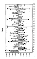
- FIG. 3 Data from the application of the method according to the invention to a human patient are reproduced.
- the upper part of the graph shows the heart curve determined by the measuring electronics.
- the lower part of the graph shows the difference between the standard value and the computationally processed data point. This results in the comparison of the standard value fluctuations upwards or downwards. If the patient is exposed to a stimulus which does not affect him, ie he does not have to process it with energy, the value remains within the normal fluctuation range.
- the conspicuous resonant frequencies are displayed by the device in a graphically processed form (see FIG. 4 ).
- Both baseline values which have a toning (ie, enhancing) effect and a sedating (ie, attenuating) effect of cardiac activity, are of interest for both diagnosis and therapy, and are automatically harmonized with the +/- bipolar function.
- the 20 strongest resonant frequency baseline values can also be selected by manual input.
- the respectively marked resonant frequencies are taken over after confirmation by the user and can thus be further processed and analyzed in the last step.
- Step 7 Result and calculation of the therapy programs
- the won resonance frequencies are further processed. These can be sorted by their polarity, by the increasing frequency base value, or by the magnitude of the change they produce. The latter sorting makes the most sense here.
- the individual frequency basic values can be further analyzed.
- the resonance values can also be stored in the sort order selected on a memory card.
- Example 2 Application Example - Patient A
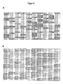
- FIG. 5B is the stored in the database frequency pattern for gallbladder inflammation with a total of 52 frequency baseline values.
- FIG. 6 the comparison of this stored pattern with the determined resonant frequencies of a match of 89%, thus indicating a corresponding disease.
- Example 3 Application Example - Patient B
- the resonance frequency basic values - as in Example 1 - were determined with the bioresonance device.
- the ascertained 56 resonance frequency basic values are in FIG. 7 listed.
- the system found the program number 43.11 rhinitis, then the program number 43.20, bronchial asthma.
- the bioresonance device therefore proposes these therapy programs as the two most important therapy programs for this patient.
- both the resonance frequency basic values and the therapy programs were then stored and provided on a memory card for the subsequent therapy of the patient.
- Example 4 Construction of a bioresonance device according to the invention
- the bioresonance device has the following components: By means of a connection for electrodes which detect the cardiovascular measured values, in particular the heart rate, these measured values are fed into the device. Within the device, the measured values are evaluated in an electronic data processing unit for determining the heart rate variability and forwarded to the main processor (CPU). In the main processor, the comparison of the collected heart rate variability with a setpoint, which is specified as a threshold. Above this threshold, the control of the frequency generator module is changed accordingly. The spectrum of electromagnetic frequencies generated by the frequency generator module is transmitted to the patient via frequency outputs and electrodes attached thereto. For external control of the bioresonance device, it has a touch panel.
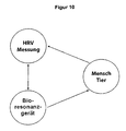
- FIG. 10 is shown schematically the control loop, as it results from the application of the method according to the invention.
- the bioresonance device acts on the human or the animal as a patient.
- the resulting variability of the heart rate is measured by means of a measuring probe and fed back into the bioresonance device, which retains the generated frequency spectrum depending on the measured heart rate variability or modifies according to a predetermined algorithm.
- the generated electromagnetic frequency spectrum is to be understood as a controlled system, the heart rate variability as a controlled variable and the CPU of the bioresonance device as a controller.
Landscapes
- Health & Medical Sciences (AREA)
- Engineering & Computer Science (AREA)
- Biomedical Technology (AREA)
- Nuclear Medicine, Radiotherapy & Molecular Imaging (AREA)
- Radiology & Medical Imaging (AREA)
- Life Sciences & Earth Sciences (AREA)
- Animal Behavior & Ethology (AREA)
- General Health & Medical Sciences (AREA)
- Public Health (AREA)
- Veterinary Medicine (AREA)
- Measurement And Recording Of Electrical Phenomena And Electrical Characteristics Of The Living Body (AREA)
Applications Claiming Priority (1)
| Application Number | Priority Date | Filing Date | Title |
|---|---|---|---|
| DE102013007448.7A DE102013007448A1 (de) | 2013-05-02 | 2013-05-02 | Verfahren zum Betrieb eines Bioresonanzgeräts |
Publications (3)
| Publication Number | Publication Date |
|---|---|
| EP2799110A1 true EP2799110A1 (fr) | 2014-11-05 |
| EP2799110C0 EP2799110C0 (fr) | 2024-02-28 |
| EP2799110B1 EP2799110B1 (fr) | 2024-02-28 |
Family
ID=50685724
Family Applications (1)
| Application Number | Title | Priority Date | Filing Date |
|---|---|---|---|
| EP14001541.3A Active EP2799110B1 (fr) | 2013-05-02 | 2014-05-02 | Dispositif médical pour l'enregistrement et la génération de fréquences de résonance |
Country Status (3)
| Country | Link |
|---|---|
| EP (1) | EP2799110B1 (fr) |
| DE (1) | DE102013007448A1 (fr) |
| ES (1) | ES2973325T3 (fr) |
Cited By (4)
| Publication number | Priority date | Publication date | Assignee | Title |
|---|---|---|---|---|
| DE102017005051A1 (de) | 2017-05-26 | 2018-11-29 | Apere GmbH & Co. KG | Refraktärzeitengenerator zur Steuerung therapeutisch wirksamer elektromagnetischer Signale |
| WO2020007441A1 (fr) | 2018-07-02 | 2020-01-09 | Apere GmbH & Co. KG | Générateur de périodes réfractaires pour la commande de signaux électromagnétiques à action thérapeutique |
| CN111568423A (zh) * | 2019-02-15 | 2020-08-25 | 南京昇翠人工智能有限公司 | 用户呼吸的共振频率估计值的量测方法及装置 |
| EP3782546A1 (fr) | 2019-08-20 | 2021-02-24 | Rayonex Biomedical GmbH | Procédé d'identification d'un point d'acupuncture et/ou de méridien |
Citations (4)
| Publication number | Priority date | Publication date | Assignee | Title |
|---|---|---|---|---|
| EP0686406A1 (fr) * | 1993-04-23 | 1995-12-13 | PETRENKO, Sergei Ivanovich | Dispositif de modification de l'activite d'une cellule biologique |
| DE19752934A1 (de) * | 1997-05-23 | 1998-12-03 | Siegfried Dr Kiontke | Gerät zum Aufschwingen physiologischer Signale auf einen Trägerstoff |
| DE102009002134A1 (de) * | 2009-04-02 | 2010-10-28 | Plank, Elisabeth, Dr. | Verwendung der Herzratenvariabilitätsänderung zur Korrelation von Magnetfeldänderungen mit der physiologischen Befindlichkeit und Verfahren dafür |
| EP2450075A1 (fr) * | 2010-11-03 | 2012-05-09 | Beniamino Palmieri | Appareil de fourniture d'énergie au corps d'un patient en fonction des paramètres biologiques du patient |
Family Cites Families (3)
| Publication number | Priority date | Publication date | Assignee | Title |
|---|---|---|---|---|
| US6450942B1 (en) * | 1999-08-20 | 2002-09-17 | Cardiorest International Ltd. | Method for reducing heart loads in mammals |
| AT504713B1 (de) * | 2007-01-09 | 2011-02-15 | Lingg Gerhard | Vorrichtung zum applizieren von gespeicherten frequenzinformationen |
| JP5148992B2 (ja) * | 2007-12-27 | 2013-02-20 | 芳裕 山口 | 心電図波形処理システム及びプログラム |
-
2013
- 2013-05-02 DE DE102013007448.7A patent/DE102013007448A1/de not_active Ceased
-
2014
- 2014-05-02 ES ES14001541T patent/ES2973325T3/es active Active
- 2014-05-02 EP EP14001541.3A patent/EP2799110B1/fr active Active
Patent Citations (4)
| Publication number | Priority date | Publication date | Assignee | Title |
|---|---|---|---|---|
| EP0686406A1 (fr) * | 1993-04-23 | 1995-12-13 | PETRENKO, Sergei Ivanovich | Dispositif de modification de l'activite d'une cellule biologique |
| DE19752934A1 (de) * | 1997-05-23 | 1998-12-03 | Siegfried Dr Kiontke | Gerät zum Aufschwingen physiologischer Signale auf einen Trägerstoff |
| DE102009002134A1 (de) * | 2009-04-02 | 2010-10-28 | Plank, Elisabeth, Dr. | Verwendung der Herzratenvariabilitätsänderung zur Korrelation von Magnetfeldänderungen mit der physiologischen Befindlichkeit und Verfahren dafür |
| EP2450075A1 (fr) * | 2010-11-03 | 2012-05-09 | Beniamino Palmieri | Appareil de fourniture d'énergie au corps d'un patient en fonction des paramètres biologiques du patient |
Non-Patent Citations (2)
| Title |
|---|
| RAYONEX: "4. User Manual of the Rayocomp PS 1000 Polar Contents", 10 August 2010 (2010-08-10), Internet, pages 1 - 99, XP055132394, Retrieved from the Internet <URL:http://www.extrao.fr/index.php/image/news/76/9000EN_FB069_4_Benutzerhandbuch_PS1000polar_Rev3.pdf> [retrieved on 20140730] * |
| RAYONEX: "Rayocomp PS 10 Portable High-Performance Bio-Resonator User Manual", 15 September 2011 (2011-09-15), Internet, pages 1 - 72, XP055132391, Retrieved from the Internet <URL:http://www.extrao.fr/index.php/image/news/75/9100EN_FB-146_Rayocomp_PS_10_Handbuch_Rev28.pdf> [retrieved on 20140730] * |
Cited By (6)
| Publication number | Priority date | Publication date | Assignee | Title |
|---|---|---|---|---|
| DE102017005051A1 (de) | 2017-05-26 | 2018-11-29 | Apere GmbH & Co. KG | Refraktärzeitengenerator zur Steuerung therapeutisch wirksamer elektromagnetischer Signale |
| WO2020007441A1 (fr) | 2018-07-02 | 2020-01-09 | Apere GmbH & Co. KG | Générateur de périodes réfractaires pour la commande de signaux électromagnétiques à action thérapeutique |
| CN111568423A (zh) * | 2019-02-15 | 2020-08-25 | 南京昇翠人工智能有限公司 | 用户呼吸的共振频率估计值的量测方法及装置 |
| CN111568423B (zh) * | 2019-02-15 | 2023-03-03 | 南京昇翠人工智能有限公司 | 用户呼吸的共振频率估计值的量测方法及装置 |
| EP3782546A1 (fr) | 2019-08-20 | 2021-02-24 | Rayonex Biomedical GmbH | Procédé d'identification d'un point d'acupuncture et/ou de méridien |
| WO2021032803A1 (fr) | 2019-08-20 | 2021-02-25 | Rayonex Biomedical Gmbh | Procédé d'identification d'un point d'acupuncture et/ou d'un méridien |
Also Published As
| Publication number | Publication date |
|---|---|
| EP2799110C0 (fr) | 2024-02-28 |
| ES2973325T3 (es) | 2024-06-19 |
| DE102013007448A1 (de) | 2014-11-20 |
| EP2799110B1 (fr) | 2024-02-28 |
Similar Documents
| Publication | Publication Date | Title |
|---|---|---|
| EP2887861B1 (fr) | Appareil pour étudier une distribution de phases pour identifier une interaction pathologique entre différentes régions du cerveau | |
| DE60210086T2 (de) | Echtzeit hochfrequenz-qrs-elektrokardiograph | |
| DE69531728T2 (de) | Gerät zur messung und auswertung der elektrischen stabilität des herzens | |
| DE60114658T2 (de) | Überwachungsgerät zur überwachung der diastolischen relaxation durch impedanzmessung | |
| DE102008002933A1 (de) | Datenaufzeichnung zur Patientenstatusanalyse | |
| EP2547251A2 (fr) | Procédé permettant de déterminer l'activité du parasympathique et/ou sympathique du système nerveux autonome d'un être vivant | |
| EP4239648B1 (fr) | Procédé de surveillance cardiaque | |
| DE10211765B4 (de) | Vorrichtung zur Lokalisation des Zielpunktes von Elektroden zur Hirnstimulation, insbesondere zur Tiefenhirnstimulation | |
| DE112009002463T5 (de) | Verfahren und Vorrichtung zur Messung und Behandlung von Schüttelfrost während einer therapeutischen Tempratursteuerung | |
| DE102007010353A1 (de) | Diagnose von Schlafapnoe | |
| EP3518757A1 (fr) | Surveillance de signaux biologiques, en particulier d'électrocardiogrammes | |
| WO2017050321A1 (fr) | Procédé et dispositif pour quantifier une arythmie sinusale respiratoire et utilisation d'un tel procédé ou d'un tel dispositif | |
| EP2799110B1 (fr) | Dispositif médical pour l'enregistrement et la génération de fréquences de résonance | |
| EP1279416A2 (fr) | Système d'analyse pour le contrôle de la reéducation | |
| DE102008021940A1 (de) | Stimulationsanordnung zur Messung der physiologischen Signalreaktivität | |
| Hegde et al. | A review on ECG signal processing and HRV analysis | |
| DE102009033829A1 (de) | Verfahren und Vorrichtung zum berührungslosen Herz-, Kreislauf- und Atmungsmonitoring | |
| DE69616653T2 (de) | Verfahren und Gerät zur Gewinnung und Verarbeitung von elektrokardiographischen Signalen | |
| DE102011117573A1 (de) | Verfahren und Einrichtung zum nichtinvasiven Überwachen von Schmerzstärken und zur Ermittlung von Narkosetiefen während medizinischer Eingriffe | |
| EP4221569A1 (fr) | Procédé de classification d'un enregistrement de polysomnographie en stades de sommeil définis | |
| EP4193926A1 (fr) | Estimation quantitative de l'activité de canaux d'acupuncture | |
| DE102005003678A1 (de) | Vorrichtung und Verfahren zur Messung und Beeinflussung des Blutdrucks und der Herzratenvariabilität | |
| DE102014207730B4 (de) | Verfahren, Vorrichtung und Computerprogrammprodukt zum Bestimmen eines isoelektrischen Punkts | |
| DE102004020515A1 (de) | Verfahren und Vorrichtung zur drahtlosen Aufzeichnung und Fernüberwachung von Muskelaktivitäten bei Tieren | |
| EP2413789A1 (fr) | Utilisation de modifications de la variabilité du rythme cardiaque pour établir des corrélations entre des modifications du champ magnétique et l'état psychologique, et procédé à cet effet |
Legal Events
| Date | Code | Title | Description |
|---|---|---|---|
| PUAI | Public reference made under article 153(3) epc to a published international application that has entered the european phase |
Free format text: ORIGINAL CODE: 0009012 |
|
| 17P | Request for examination filed |
Effective date: 20140502 |
|
| AK | Designated contracting states |
Kind code of ref document: A1 Designated state(s): AL AT BE BG CH CY CZ DE DK EE ES FI FR GB GR HR HU IE IS IT LI LT LU LV MC MK MT NL NO PL PT RO RS SE SI SK SM TR |
|
| AX | Request for extension of the european patent |
Extension state: BA ME |
|
| R17P | Request for examination filed (corrected) |
Effective date: 20150504 |
|
| RBV | Designated contracting states (corrected) |
Designated state(s): AL AT BE BG CH CY CZ DE DK EE ES FI FR GB GR HR HU IE IS IT LI LT LU LV MC MK MT NL NO PL PT RO RS SE SI SK SM TR |
|
| STAA | Information on the status of an ep patent application or granted ep patent |
Free format text: STATUS: EXAMINATION IS IN PROGRESS |
|
| 17Q | First examination report despatched |
Effective date: 20171012 |
|
| GRAP | Despatch of communication of intention to grant a patent |
Free format text: ORIGINAL CODE: EPIDOSNIGR1 |
|
| STAA | Information on the status of an ep patent application or granted ep patent |
Free format text: STATUS: GRANT OF PATENT IS INTENDED |
|
| GRAJ | Information related to disapproval of communication of intention to grant by the applicant or resumption of examination proceedings by the epo deleted |
Free format text: ORIGINAL CODE: EPIDOSDIGR1 |
|
| STAA | Information on the status of an ep patent application or granted ep patent |
Free format text: STATUS: EXAMINATION IS IN PROGRESS |
|
| INTG | Intention to grant announced |
Effective date: 20231013 |
|
| GRAP | Despatch of communication of intention to grant a patent |
Free format text: ORIGINAL CODE: EPIDOSNIGR1 |
|
| STAA | Information on the status of an ep patent application or granted ep patent |
Free format text: STATUS: GRANT OF PATENT IS INTENDED |
|
| INTC | Intention to grant announced (deleted) | ||
| INTG | Intention to grant announced |
Effective date: 20231113 |
|
| GRAS | Grant fee paid |
Free format text: ORIGINAL CODE: EPIDOSNIGR3 |
|
| GRAA | (expected) grant |
Free format text: ORIGINAL CODE: 0009210 |
|
| STAA | Information on the status of an ep patent application or granted ep patent |
Free format text: STATUS: THE PATENT HAS BEEN GRANTED |
|
| AK | Designated contracting states |
Kind code of ref document: B1 Designated state(s): AL AT BE BG CH CY CZ DE DK EE ES FI FR GB GR HR HU IE IS IT LI LT LU LV MC MK MT NL NO PL PT RO RS SE SI SK SM TR |
|
| REG | Reference to a national code |
Ref country code: GB Ref legal event code: FG4D Free format text: NOT ENGLISH |
|
| REG | Reference to a national code |
Ref country code: CH Ref legal event code: EP |
|
| REG | Reference to a national code |
Ref country code: DE Ref legal event code: R096 Ref document number: 502014016775 Country of ref document: DE |
|
| REG | Reference to a national code |
Ref country code: IE Ref legal event code: FG4D Free format text: LANGUAGE OF EP DOCUMENT: GERMAN |
|
| U01 | Request for unitary effect filed |
Effective date: 20240319 |
|
| U07 | Unitary effect registered |
Designated state(s): AT BE BG DE DK EE FI FR IT LT LU LV MT NL PT SE SI Effective date: 20240326 |
|
| REG | Reference to a national code |
Ref country code: ES Ref legal event code: FG2A Ref document number: 2973325 Country of ref document: ES Kind code of ref document: T3 Effective date: 20240619 |
|
| U20 | Renewal fee for the european patent with unitary effect paid |
Year of fee payment: 11 Effective date: 20240516 |
|
| PG25 | Lapsed in a contracting state [announced via postgrant information from national office to epo] |
Ref country code: IS Free format text: LAPSE BECAUSE OF FAILURE TO SUBMIT A TRANSLATION OF THE DESCRIPTION OR TO PAY THE FEE WITHIN THE PRESCRIBED TIME-LIMIT Effective date: 20240628 |
|
| PG25 | Lapsed in a contracting state [announced via postgrant information from national office to epo] |
Ref country code: GR Free format text: LAPSE BECAUSE OF FAILURE TO SUBMIT A TRANSLATION OF THE DESCRIPTION OR TO PAY THE FEE WITHIN THE PRESCRIBED TIME-LIMIT Effective date: 20240529 |
|
| PG25 | Lapsed in a contracting state [announced via postgrant information from national office to epo] |
Ref country code: RS Free format text: LAPSE BECAUSE OF FAILURE TO SUBMIT A TRANSLATION OF THE DESCRIPTION OR TO PAY THE FEE WITHIN THE PRESCRIBED TIME-LIMIT Effective date: 20240528 Ref country code: HR Free format text: LAPSE BECAUSE OF FAILURE TO SUBMIT A TRANSLATION OF THE DESCRIPTION OR TO PAY THE FEE WITHIN THE PRESCRIBED TIME-LIMIT Effective date: 20240228 |
|
| PG25 | Lapsed in a contracting state [announced via postgrant information from national office to epo] |
Ref country code: RS Free format text: LAPSE BECAUSE OF FAILURE TO SUBMIT A TRANSLATION OF THE DESCRIPTION OR TO PAY THE FEE WITHIN THE PRESCRIBED TIME-LIMIT Effective date: 20240528 Ref country code: NO Free format text: LAPSE BECAUSE OF FAILURE TO SUBMIT A TRANSLATION OF THE DESCRIPTION OR TO PAY THE FEE WITHIN THE PRESCRIBED TIME-LIMIT Effective date: 20240528 Ref country code: IS Free format text: LAPSE BECAUSE OF FAILURE TO SUBMIT A TRANSLATION OF THE DESCRIPTION OR TO PAY THE FEE WITHIN THE PRESCRIBED TIME-LIMIT Effective date: 20240628 Ref country code: HR Free format text: LAPSE BECAUSE OF FAILURE TO SUBMIT A TRANSLATION OF THE DESCRIPTION OR TO PAY THE FEE WITHIN THE PRESCRIBED TIME-LIMIT Effective date: 20240228 Ref country code: GR Free format text: LAPSE BECAUSE OF FAILURE TO SUBMIT A TRANSLATION OF THE DESCRIPTION OR TO PAY THE FEE WITHIN THE PRESCRIBED TIME-LIMIT Effective date: 20240529 |
|
| PG25 | Lapsed in a contracting state [announced via postgrant information from national office to epo] |
Ref country code: PL Free format text: LAPSE BECAUSE OF FAILURE TO SUBMIT A TRANSLATION OF THE DESCRIPTION OR TO PAY THE FEE WITHIN THE PRESCRIBED TIME-LIMIT Effective date: 20240228 |
|
| PG25 | Lapsed in a contracting state [announced via postgrant information from national office to epo] |
Ref country code: PL Free format text: LAPSE BECAUSE OF FAILURE TO SUBMIT A TRANSLATION OF THE DESCRIPTION OR TO PAY THE FEE WITHIN THE PRESCRIBED TIME-LIMIT Effective date: 20240228 |
|
| PG25 | Lapsed in a contracting state [announced via postgrant information from national office to epo] |
Ref country code: SM Free format text: LAPSE BECAUSE OF FAILURE TO SUBMIT A TRANSLATION OF THE DESCRIPTION OR TO PAY THE FEE WITHIN THE PRESCRIBED TIME-LIMIT Effective date: 20240228 |
|
| PG25 | Lapsed in a contracting state [announced via postgrant information from national office to epo] |
Ref country code: CZ Free format text: LAPSE BECAUSE OF FAILURE TO SUBMIT A TRANSLATION OF THE DESCRIPTION OR TO PAY THE FEE WITHIN THE PRESCRIBED TIME-LIMIT Effective date: 20240228 |
|
| PG25 | Lapsed in a contracting state [announced via postgrant information from national office to epo] |
Ref country code: SK Free format text: LAPSE BECAUSE OF FAILURE TO SUBMIT A TRANSLATION OF THE DESCRIPTION OR TO PAY THE FEE WITHIN THE PRESCRIBED TIME-LIMIT Effective date: 20240228 |
|
| PG25 | Lapsed in a contracting state [announced via postgrant information from national office to epo] |
Ref country code: SM Free format text: LAPSE BECAUSE OF FAILURE TO SUBMIT A TRANSLATION OF THE DESCRIPTION OR TO PAY THE FEE WITHIN THE PRESCRIBED TIME-LIMIT Effective date: 20240228 Ref country code: SK Free format text: LAPSE BECAUSE OF FAILURE TO SUBMIT A TRANSLATION OF THE DESCRIPTION OR TO PAY THE FEE WITHIN THE PRESCRIBED TIME-LIMIT Effective date: 20240228 Ref country code: RO Free format text: LAPSE BECAUSE OF FAILURE TO SUBMIT A TRANSLATION OF THE DESCRIPTION OR TO PAY THE FEE WITHIN THE PRESCRIBED TIME-LIMIT Effective date: 20240228 Ref country code: CZ Free format text: LAPSE BECAUSE OF FAILURE TO SUBMIT A TRANSLATION OF THE DESCRIPTION OR TO PAY THE FEE WITHIN THE PRESCRIBED TIME-LIMIT Effective date: 20240228 |
|
| REG | Reference to a national code |
Ref country code: DE Ref legal event code: R097 Ref document number: 502014016775 Country of ref document: DE |
|
| PLBE | No opposition filed within time limit |
Free format text: ORIGINAL CODE: 0009261 |
|
| STAA | Information on the status of an ep patent application or granted ep patent |
Free format text: STATUS: NO OPPOSITION FILED WITHIN TIME LIMIT |
|
| PG25 | Lapsed in a contracting state [announced via postgrant information from national office to epo] |
Ref country code: MC Free format text: LAPSE BECAUSE OF FAILURE TO SUBMIT A TRANSLATION OF THE DESCRIPTION OR TO PAY THE FEE WITHIN THE PRESCRIBED TIME-LIMIT Effective date: 20240228 |
|
| PG25 | Lapsed in a contracting state [announced via postgrant information from national office to epo] |
Ref country code: MC Free format text: LAPSE BECAUSE OF FAILURE TO SUBMIT A TRANSLATION OF THE DESCRIPTION OR TO PAY THE FEE WITHIN THE PRESCRIBED TIME-LIMIT Effective date: 20240228 |
|
| 26N | No opposition filed |
Effective date: 20241129 |
|
| U1N | Appointed representative for the unitary patent procedure changed after the registration of the unitary effect |
Representative=s name: HOFFMANN EITLE; DE |
|
| PG25 | Lapsed in a contracting state [announced via postgrant information from national office to epo] |
Ref country code: IE Free format text: LAPSE BECAUSE OF NON-PAYMENT OF DUE FEES Effective date: 20240502 |
|
| U20 | Renewal fee for the european patent with unitary effect paid |
Year of fee payment: 12 Effective date: 20250516 |
|
| PGFP | Annual fee paid to national office [announced via postgrant information from national office to epo] |
Ref country code: GB Payment date: 20250522 Year of fee payment: 12 Ref country code: ES Payment date: 20250616 Year of fee payment: 12 |
|
| PGFP | Annual fee paid to national office [announced via postgrant information from national office to epo] |
Ref country code: CH Payment date: 20250601 Year of fee payment: 12 |
|
| PG25 | Lapsed in a contracting state [announced via postgrant information from national office to epo] |
Ref country code: CY Free format text: LAPSE BECAUSE OF FAILURE TO SUBMIT A TRANSLATION OF THE DESCRIPTION OR TO PAY THE FEE WITHIN THE PRESCRIBED TIME-LIMIT; INVALID AB INITIO Effective date: 20140502 |
|
| PG25 | Lapsed in a contracting state [announced via postgrant information from national office to epo] |
Ref country code: HU Free format text: LAPSE BECAUSE OF FAILURE TO SUBMIT A TRANSLATION OF THE DESCRIPTION OR TO PAY THE FEE WITHIN THE PRESCRIBED TIME-LIMIT; INVALID AB INITIO Effective date: 20140502 |