EP2799193A1 - Messer für Schneidmaschine - Google Patents
Messer für Schneidmaschine Download PDFInfo
- Publication number
- EP2799193A1 EP2799193A1 EP13166556.4A EP13166556A EP2799193A1 EP 2799193 A1 EP2799193 A1 EP 2799193A1 EP 13166556 A EP13166556 A EP 13166556A EP 2799193 A1 EP2799193 A1 EP 2799193A1
- Authority
- EP
- European Patent Office
- Prior art keywords
- slicer blade
- base body
- material thickness
- region
- area
- Prior art date
- Legal status (The legal status is an assumption and is not a legal conclusion. Google has not performed a legal analysis and makes no representation as to the accuracy of the status listed.)
- Withdrawn
Links
- 239000000463 material Substances 0.000 claims abstract description 79
- 230000001429 stepping effect Effects 0.000 claims abstract description 31
- 235000013305 food Nutrition 0.000 claims abstract description 4
- 241000826860 Trapezium Species 0.000 claims description 5
- 238000006073 displacement reaction Methods 0.000 description 21
- 238000004088 simulation Methods 0.000 description 7
- 238000012360 testing method Methods 0.000 description 6
- 238000004364 calculation method Methods 0.000 description 4
- 238000000034 method Methods 0.000 description 3
- 230000000087 stabilizing effect Effects 0.000 description 3
- 229910000831 Steel Inorganic materials 0.000 description 2
- 238000004519 manufacturing process Methods 0.000 description 2
- 230000000717 retained effect Effects 0.000 description 2
- 239000010959 steel Substances 0.000 description 2
- 229910001315 Tool steel Inorganic materials 0.000 description 1
- 230000001133 acceleration Effects 0.000 description 1
- 230000002411 adverse Effects 0.000 description 1
- 230000009286 beneficial effect Effects 0.000 description 1
- 235000013351 cheese Nutrition 0.000 description 1
- 230000007423 decrease Effects 0.000 description 1
- 230000003247 decreasing effect Effects 0.000 description 1
- 238000013461 design Methods 0.000 description 1
- 230000000694 effects Effects 0.000 description 1
- 230000002349 favourable effect Effects 0.000 description 1
- 238000011835 investigation Methods 0.000 description 1
- 235000013372 meat Nutrition 0.000 description 1
- 238000012986 modification Methods 0.000 description 1
- 230000004048 modification Effects 0.000 description 1
- 238000000465 moulding Methods 0.000 description 1
- 230000010355 oscillation Effects 0.000 description 1
- 235000013580 sausages Nutrition 0.000 description 1
- 229910001220 stainless steel Inorganic materials 0.000 description 1
- 239000010935 stainless steel Substances 0.000 description 1
Images


Classifications
-
- B—PERFORMING OPERATIONS; TRANSPORTING
- B26—HAND CUTTING TOOLS; CUTTING; SEVERING
- B26D—CUTTING; DETAILS COMMON TO MACHINES FOR PERFORATING, PUNCHING, CUTTING-OUT, STAMPING-OUT OR SEVERING
- B26D1/00—Cutting through work characterised by the nature or movement of the cutting member or particular materials not otherwise provided for; Apparatus or machines therefor; Cutting members therefor
- B26D1/0006—Cutting members therefor
-
- B—PERFORMING OPERATIONS; TRANSPORTING
- B26—HAND CUTTING TOOLS; CUTTING; SEVERING
- B26D—CUTTING; DETAILS COMMON TO MACHINES FOR PERFORATING, PUNCHING, CUTTING-OUT, STAMPING-OUT OR SEVERING
- B26D1/00—Cutting through work characterised by the nature or movement of the cutting member or particular materials not otherwise provided for; Apparatus or machines therefor; Cutting members therefor
- B26D1/0006—Cutting members therefor
- B26D2001/0053—Cutting members therefor having a special cutting edge section or blade section
-
- B—PERFORMING OPERATIONS; TRANSPORTING
- B26—HAND CUTTING TOOLS; CUTTING; SEVERING
- B26D—CUTTING; DETAILS COMMON TO MACHINES FOR PERFORATING, PUNCHING, CUTTING-OUT, STAMPING-OUT OR SEVERING
- B26D2210/00—Machines or methods used for cutting special materials
- B26D2210/02—Machines or methods used for cutting special materials for cutting food products, e.g. food slicers
Definitions
- the present invention relates to a slicer blade for use in slicing machines for cutting foodstuff like cheese, sausage, meat and the like.
- European patent application EP 1 434 672 A1 to Weber Maschinenbau GmbH & Co. KG discloses a rotatingly driven cutting blade that comprises a stabilizing zone, wherein at least one stabilizing circularly extending arch is provided.
- German patent application DE 44 29 046 A1 teaches a slicer blade that comprises bars, preferably formed on one side of the blade and extending from the centre to the outer periphery of the blade.
- slicer blades of the state of the art have in common that irrespective the diameter thereof they have the same weight, adapted for use in predetermined slicing devices.
- the predetermined maximum weight of the slicer blade is in the area of 5,300 g.
- the common diameter of a slicer blade with a weight that does not extend over the above detailed value is in the area of between 300 mm and 480 mm.
- the problem of the invention is to overcome the drawbacks of the state of the art and to provide a slicer blade that shows high accuracy and a low deflection even with a diameter of more than 480 mm.
- a slicer blade 100 in particular for use in food slicing devices, in form of a circular disk, with an upper side and a lower side, wherein the upper side is the side that during operation faces the material to be cut, and wherein in the centre area a boss, surrounded by a boss area 3 is formed, and wherein at the circumference of the circular disk a cutting area 1 with a cutting edge is provided, and wherein base body 2 extends between boss area 3 and cutting area 1, characterized in that base body 2 comprises at least two steppings, wherein one stepping is provided at the interface 7 between cutting area 1 and base body 2 on the lower side of slicer blade 100, and the second stepping is provided at the interface 6 between boss area 3 and base body 2 at the lower side of slicer blade 100.
- a slicer blade 100 wherein the material thickness of boss area 3 is larger than the material thickness of base body 2.
- a slicer blade 100 wherein cutting area 1 emerges over the lower side of the slicer blade.
- base body 2 is provided with a region of reduced material thickness, which region is arranged rotationally symmetric along the circumference of at least one circle, which circle is concentric to the circular disk shaped slicer blade.
- a slicer blade 100 wherein the at least one region of reduced material thickness spans the entire circumference of the at least one concentric circle.
- a slicer blade 100 wherein the at least one region of reduced material thickness spans parts of the circumference of the at least one concentric circle.
- slicer blade 100 wherein at least two regions of reduced material thickness are provided in base body 2, wherein one region of reduced material thickness is a continuous region that spans the entire circumference of a concentric circle and the other region is a interrupted region that spans parts of a further concentric circle.
- a slicer blade 100 wherein the at least one region of reduced material thickness is an impression or an aperture.
- a slicer blade 100 wherein the at least one region of reduced material thickness in the top view has a base area in form of a triangle, a square, a rectangle, a circle, an ellipse or a double ellipse.
- a slicer blade 100 wherein the at least one region of reduced material thickness has the form of a groove or a slit.
- the groove has a cross section in form of a trapezium, a rectangle, a square, a triangle, a circle or an ellipse.
- a slicer blade 100 wherein base body 2 comprises a region of reduced material thickness in form of a groove with a cross section in form of a trapezium, and a region of reduced material thickness in form of a number of elliptic and/or double elliptic apertures.
- Fig. 8 shows the experimental results and simulation results in respect of displacement of a slicer blade according to the invention.
- the intended mass of a slicer blade is linked to the respective slicer machine to be used with.
- the related slicer machine is provided with a mass-balance weight in order to prevent unfavourable oscillations. Therefore all changes in respect of shape and size of the slicer blade have to be performed within the limits of the intended mass predetermined by the slicing device the slicer blade will be used with.
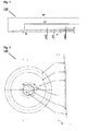
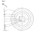
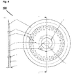
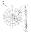
- Figs. 1 to 7 show different embodiments of slicer blade 100 according to the invention.
- slicer blade 100 according to the invention is in form of a circular disk.
- slicer blade 100 according to the invention is made of stainless steel or tool steel and is formed by cutting, moulding or a combination thereof.
- slicer blade 100 During operation the upper side of slicer blade 100 faces the material to be sliced. In the centre of slicer blade 100 a boss is formed, surrounded by boss area 3. Boss and boss area 3 serve for fixing slicer blade 100 at a slicing device (not shown). At the circumference of slicer blade 100 cutting area 1 with a cutting edge is provided to slice and split the foodstuff. It is preferred that cutting area 1 emerges over the lower side of slicer blade 100. The extent of this emerging of cutting area 1 is defined by parameter A1, shown in Fig. 1 and will be detailed later.
- Base body 2 of slicer blade 100 extends between boss area 3 and cutting area 1 and serves to stabilize the slicer blade and to connect boss area 3 and cutting area 1.
- the material thicknesses of boss area 3 and base body 2 can be equal or different.
- Fig. 6 shows an embodiment where the material thickness of the boss area 3 is larger than the maximum material thickness of base body 2.
- boss area 3 comprises means like fixing bores 9 to be used with fasteners to fix the slicer blade at a slicing machine. Furthermore, additional means, like fixing bores 9 can be provided to be used with fasteners for fixing protecting means for the blade. The protecting means help to prevent unintended contact with cutting area 1.
- boss area 3 serves to connect slicer blade 100 with a slicing device.
- the diameter of boss area 3 will depend on the slicing device and the means used for fixing slicer blade100 to said device.
- the connection between slicer blade 100 and slicing device is performed via a plane clamping plate and a pin extending through the boss of slicer blade 100.
- common clamping plates of the state of the art have a diameter of between 90 mm and 100 mm.
- the diameter of boss area 3 usually is between 50 mm and 100 mm, but depending on the presets defined by a certain slicing device the diameter of boss area 3 of the slicer blade 100 according to the invention can be adapted accordingly.
- Slicer blade 100 shows a comparably reduced deflection of the cutting area during operation. This effect is achieved by introducing at least two steppings in base body 2. One stepping of these at least two steppings is arranged at the upper side of slicer blade 100 at the interface 7 between base body 2 and cutting area 1. The second stepping of the at least two steppings is arranged at the lower side of slicer blade 100 at the interface 6 between boss area 3 and base body 2. The position of the interface between base body 2 and cutting area 1 depends on the diameter of slicer blade 100 and the diameter of cutting area 1. In the state of the art a well established diameter of a cutting area is in the area of 120 mm. In a preferred embodiment of the invention the diameter of boss area 3 is 100 mm and thus the stepping between boss area 3 and base body 2 starts at a diameter of about 100 mm. The edges of the steppings can be smooth or angular.
- the angle of elevation ⁇ of the stepping between boss area 3 and base body 2 is between 30° and 90°, in particular angle ⁇ is 45°.
- the angle of elevation ⁇ of the stepping between base body 2 and cutting area 1 is between 30° and 90°, in particular angle ⁇ is 45°.
- Figs. 3 to 6 show a slicer blade according to the invention with areas of reduced material thickness.
- the inventors have found that the introduction of regions with reduced thickness of material in base body 2 can help to stiffen slicer blade 100 and thus help to reduce deflections.
- reduced material thickness means that the cross section in the respective region of the slicer blade is decreased and the maximum reduction of material thickness in this context is a perforation.
- wall thickness can be synonymously used for "material thickness”.
- the reduction of material thickness can be performed by any means known in the state of the art like ablating material or by perforating of the slicer blade.
- the regions of reduced material thickness are arranged rotationally symmetric along the circumference of at least one circle, which circle is concentric to the circular disk shaped slicer blade 100.
- the region of reduced material thickness spans an entire circle. That means that the region of reduced material thickness continuously extends along said circle without leaving on this circle any area of non reduced material thickness.
- continuous region of reduced material thickness is used synonymously.
- slicer blade 100 comprises more than one region of reduced material thickness.
- Figs. 5 and 6 show embodiments of the invention wherein slicer blade 100 has two regions of reduced material thickness, one spanning an entire concentric circle and the other region spanning only parts of a second concentric circle.
- Fig. 6 shows a slicer blade according to the invention wherein a large stepping between boss and base body is formed, and wherein two regions of reduced material thickness are formed.
- the material thickness in boss area 3 is larger than the material thickness in base body 2.
- Slicer blade 100 according to the invention shows reduced distortion and deviation compared to slicer blades of the state of the art.
- the first Eigen frequency of the slicer blade according to the invention during operation is higher than the critical speed.
- the mass inertia of slicer blade 100 according to the invention is reduced compared to slicer blades of the state of the art with the same diameter. This helps to reduce the amount of energy needed for acceleration and deferment of the slicer blade.
- slicer blade 100 according to the invention even with increasing diameter of the slicer blade the favourable characteristics of the slicer blade are retained. It was found that slicer blade 100 according to the invention, even with a diameter of more than 480 mm, still shows a reduced deflection compared with slicer blades of the state of the art. According to simulations using the Finite Element Method (FEM) the inventors found out that an embodiment of the invention with a diameter of 520 mm still shows very good results.
- FEM Finite Element Method
- the mass of slicer blade 100 can be adjusted to an intended mass that is predetermined for a certain slicing device.
- the slicer blade according to the invention can have a diameter of up to 520 mm by retaining the intended mass and with negligible distortion. This allows for the slicing of a greater amount of food within a certain time period compared to slicer blades with lower diameters.
- the inventors have surprisingly found that a combination of continuous and interrupted regions of reduced material thickness in base body 2 is highly preferred. Especially preferred is an embodiment of the slicer blade wherein the cross section of the continuous region of reduced material thickness is in form of a triangle or trapezium. Furthermore preferred is that the interrupted region of reduced material thickness comprises recesses and/or perforations that in top view are in form of a double ellipse.
- the wall thickness of base body 2 in the region of reduced material thickness is not lower than 3 mm.
- the thickness of the wall in regions without reduced material thickness in base body 2 and in boss area 3 is preferably between 4.0 mm and 10.0 mm, and especially about 5 mm.
- Fig. 1 a half section of a slicer blade according to the invention is shown. Indicated are the external diameter of the slicer blade (d1), the external diameter of base body 2 (d2), angles ⁇ and ⁇ , the wall thickness of base body 2 (material thickness mt2) and wall thickness (material thickness) of boss area 3 (mt3).
- parameter A1 is defined as the axial distance between the peek of the cutting edge and base body 2.
- parameter A1 the total displacement at the blade edge.
- parameter A1 has a reversal point where almost complete extermination of displacement at the blade edge during pure rotation can be reached. But at this point the slicer blade forms an unstable equilibrium and should not be manufactured. If parameter A1 has a value that is lower than this reversal point the cutting area moves in the direction of the material to be sliced. If A1 is larger than the value at the reversal point the cutting area is displaced in the direction of the boss and therefore moves away from the material to be sliced. Near to the turning point the maximum of displacement lies in the region of the base body.
- the inventors found that the reversal point for A1 shifts to higher values.
- the inventors investigated the characteristics of a slicer blade according to the invention with the same diameter of 480 mm but with a continuous region of reduced material thickness and with an interrupted region of reduced material thickness.
- the reversal point for A1 is near to 1.90 mm and with a displacement of only 0.12 mm this embodiment is particularly preferred.
- the slicer blade shown in Fig. 7 has a conical cutting area 1 and two steppings. One stepping is situated at the interface between base body 2 and cutting area 1, the second stepping is provided at the interface between base body 2 and boss area 3. An interrupted region of reduced material thickness in form of 6 elliptic perforations is arranged in base body 2. The passage between boss area 3 and base body 2 has an angle ⁇ of 45° and the stepping edge is elliptically rounded.
- parameter A1 is 2.00 mm and the outer diameter d1 of the slicer blade is 480 mm.
- the comparatively high deviation is caused by the characteristic design of the slicer blade according to the invention. Therefore it is recommended to use linear calculations with geometric non-linearities.
- Fig. 8 the results in respect of displacement of the slicer blade under investigation are presented.
- the presentation of the results in form of curves illustrate that the aim to maximally get a displacement of 1 mm at 5,600 rpm at the cutting edge was reached with results showing even much lower values for displacement. Beside this according the operating personnel rated the noise generation to be moderate and not annoying.
- Examples 2 and 3 show results for two further embodiments of the present invention derived using the Finite Element Method.
- the slicer blade shown in Figs. 1 and 2 (without regions of reduced material thickness) was investigated.
- the outer diameter of this slicer blade is 480 mm, the wall thickness (material thickness) is 4.8 mm.
- the intended weight is 5,250 ⁇ 50 g.
- the slicer blade is made of steel (AISI D2).
- Table 2 shows the influence of the change of parameters A1 to the maximum of the displacement in the blade axis direction (max_disp_x), the maximum of the comparison stress (max_stress_vm) and the total mass (total_mass).
- maximum of displacement can be found at base body.
- the maximum of the comparison stress is a notch stress, which can be found at the Interface between base body and boss area. With increasing value of the parameter A1 the stress rises, however, the yield strength of the material with a value of 420 N / mm 2 is not exceeded.
- the underlined values show the optimum for manufacturing.
- the slicer blade shown in Fig. 6 was investigated. This embodiment is provided with a continuous area of reduced material thickness and an interrupted area of perforations. The outer diameter of this slicer blade is 480 mm, the value for wall thickness differs between the different areas. The intended weight is 5,250 ⁇ 50 g.
- the slicer blade is made of steel (AISI D2).
- the maximum of the comparison stress is a notch stress, which can be found at the Interface between base body and boss area. With increasing value of the parameter A1 the stress decreases. The yield strength of the material with a value of 420 N /mm 2 is not exceeded. The underlined values show the optimum for manufacturing.
Landscapes
- Life Sciences & Earth Sciences (AREA)
- Forests & Forestry (AREA)
- Engineering & Computer Science (AREA)
- Mechanical Engineering (AREA)
- Food-Manufacturing Devices (AREA)
Priority Applications (3)
| Application Number | Priority Date | Filing Date | Title |
|---|---|---|---|
| EP13166556.4A EP2799193A1 (de) | 2013-05-03 | 2013-05-03 | Messer für Schneidmaschine |
| PCT/EP2014/059021 WO2014177711A1 (en) | 2013-05-03 | 2014-05-02 | Slicer blade |
| EP14728463.2A EP2895307A1 (de) | 2013-05-03 | 2014-05-02 | Schneidklinge |
Applications Claiming Priority (1)
| Application Number | Priority Date | Filing Date | Title |
|---|---|---|---|
| EP13166556.4A EP2799193A1 (de) | 2013-05-03 | 2013-05-03 | Messer für Schneidmaschine |
Publications (1)
| Publication Number | Publication Date |
|---|---|
| EP2799193A1 true EP2799193A1 (de) | 2014-11-05 |
Family
ID=48288887
Family Applications (2)
| Application Number | Title | Priority Date | Filing Date |
|---|---|---|---|
| EP13166556.4A Withdrawn EP2799193A1 (de) | 2013-05-03 | 2013-05-03 | Messer für Schneidmaschine |
| EP14728463.2A Withdrawn EP2895307A1 (de) | 2013-05-03 | 2014-05-02 | Schneidklinge |
Family Applications After (1)
| Application Number | Title | Priority Date | Filing Date |
|---|---|---|---|
| EP14728463.2A Withdrawn EP2895307A1 (de) | 2013-05-03 | 2014-05-02 | Schneidklinge |
Country Status (2)
| Country | Link |
|---|---|
| EP (2) | EP2799193A1 (de) |
| WO (1) | WO2014177711A1 (de) |
Cited By (2)
| Publication number | Priority date | Publication date | Assignee | Title |
|---|---|---|---|---|
| US20210178620A1 (en) * | 2019-12-16 | 2021-06-17 | TVI Entwicklung & Produktion GmbH | Blade, slicing machine equipped therewith and method of operating the slicing machine |
| US11890773B2 (en) * | 2019-06-03 | 2024-02-06 | Multivac Sepp Haggenmueller SE & Co., KG | Knife, in particular for slicers |
Citations (8)
| Publication number | Priority date | Publication date | Assignee | Title |
|---|---|---|---|---|
| DE6940978U (de) * | 1969-10-22 | 1970-04-30 | Anny Enke | Aufschnittmaschinen-messer |
| DE2306822A1 (de) * | 1973-02-12 | 1974-08-15 | Paul Dipl Ing Kohlhaas | Scheibenmesser, insbesondere umlaufendes scheibenmesser |
| DE4431382A1 (de) * | 1994-08-29 | 1996-03-07 | Mws Schneidwerkzeuge Gmbh | Rundmesser für Allesschneider |
| DE29520856U1 (de) * | 1994-08-16 | 1996-04-11 | Biforce Anstalt, Vaduz | Slicermesser |
| DE29605039U1 (de) * | 1996-03-08 | 1996-05-15 | Wabäma GmbH Spezialfabrik für Schneidemaschinen, 42781 Haan | Messer für Schneidvorrichtung |
| DE29800868U1 (de) * | 1998-01-20 | 1999-05-20 | Rasspe International GmbH & Co. KG, 42651 Solingen | Rundmesser |
| EP1378328A2 (de) * | 2002-07-01 | 2004-01-07 | Premark FEG L.L.C. | Kreisförmiges Verbundmesser für Aufschnittschneider |
| WO2013079550A1 (en) * | 2011-12-01 | 2013-06-06 | Scattolin Gaetano | Circular blade for food slicers |
Family Cites Families (2)
| Publication number | Priority date | Publication date | Assignee | Title |
|---|---|---|---|---|
| DE4429046A1 (de) | 1994-08-16 | 1996-02-22 | Biforce Anstalt | Slicermesser |
| DE10155048A1 (de) | 2001-11-09 | 2003-05-22 | Weber Maschb Gmbh & Co Kg | Rotierend antreibbares Schneidmesser |
-
2013
- 2013-05-03 EP EP13166556.4A patent/EP2799193A1/de not_active Withdrawn
-
2014
- 2014-05-02 WO PCT/EP2014/059021 patent/WO2014177711A1/en not_active Ceased
- 2014-05-02 EP EP14728463.2A patent/EP2895307A1/de not_active Withdrawn
Patent Citations (8)
| Publication number | Priority date | Publication date | Assignee | Title |
|---|---|---|---|---|
| DE6940978U (de) * | 1969-10-22 | 1970-04-30 | Anny Enke | Aufschnittmaschinen-messer |
| DE2306822A1 (de) * | 1973-02-12 | 1974-08-15 | Paul Dipl Ing Kohlhaas | Scheibenmesser, insbesondere umlaufendes scheibenmesser |
| DE29520856U1 (de) * | 1994-08-16 | 1996-04-11 | Biforce Anstalt, Vaduz | Slicermesser |
| DE4431382A1 (de) * | 1994-08-29 | 1996-03-07 | Mws Schneidwerkzeuge Gmbh | Rundmesser für Allesschneider |
| DE29605039U1 (de) * | 1996-03-08 | 1996-05-15 | Wabäma GmbH Spezialfabrik für Schneidemaschinen, 42781 Haan | Messer für Schneidvorrichtung |
| DE29800868U1 (de) * | 1998-01-20 | 1999-05-20 | Rasspe International GmbH & Co. KG, 42651 Solingen | Rundmesser |
| EP1378328A2 (de) * | 2002-07-01 | 2004-01-07 | Premark FEG L.L.C. | Kreisförmiges Verbundmesser für Aufschnittschneider |
| WO2013079550A1 (en) * | 2011-12-01 | 2013-06-06 | Scattolin Gaetano | Circular blade for food slicers |
Cited By (3)
| Publication number | Priority date | Publication date | Assignee | Title |
|---|---|---|---|---|
| US11890773B2 (en) * | 2019-06-03 | 2024-02-06 | Multivac Sepp Haggenmueller SE & Co., KG | Knife, in particular for slicers |
| US20210178620A1 (en) * | 2019-12-16 | 2021-06-17 | TVI Entwicklung & Produktion GmbH | Blade, slicing machine equipped therewith and method of operating the slicing machine |
| US11667047B2 (en) * | 2019-12-16 | 2023-06-06 | TVI Entwicklung & Produktion GmbH | Blade, slicing machine equipped therewith and method of operating the slicing machine |
Also Published As
| Publication number | Publication date |
|---|---|
| EP2895307A1 (de) | 2015-07-22 |
| WO2014177711A1 (en) | 2014-11-06 |
Similar Documents
| Publication | Publication Date | Title |
|---|---|---|
| AU2016208383B2 (en) | Methods and Equipment for Cutting Food Products | |
| EP2112964B1 (de) | Vorrichtung und verfahren zum schneiden von lebensmitteln | |
| EP2650090B1 (de) | Schneidmesser mit Abweiselement | |
| WO2015088678A1 (en) | Slicing blade system | |
| JP2017509502A (ja) | 直線縁部を有する形状用の高性能回転切断装置 | |
| EP2895307A1 (de) | Schneidklinge | |
| US5038649A (en) | Food slicer adapter | |
| KR101811511B1 (ko) | 타이어 컴포넌트들을 절단하기 위한 절단 디바이스 | |
| US9604379B2 (en) | Dicing machines and methods of use | |
| US20120174722A1 (en) | Cutting blade | |
| CN208290003U (zh) | 低阻力刀片分条装置 | |
| US20070119285A1 (en) | Cutting blade that can be rotationally driven | |
| AU2014363917B2 (en) | Knife assembly with tab blade | |
| EP3116694B1 (de) | Würfelschneider und verfahren zur verwendung | |
| CN213592969U (zh) | 一种切丁用刀盘 | |
| JP3090734B2 (ja) | 塊状食品の切断装置 | |
| KR101960228B1 (ko) | 와이어를 이용한 다기능 식재료 절단기 | |
| GB2339526A (en) | Slicing machine with rotating knife and deflector | |
| US20250289156A1 (en) | Food slicer | |
| JP5815244B2 (ja) | スライサー | |
| JP3207737U (ja) | 食パン | |
| CN206123783U (zh) | 电动切丝切片装置 | |
| JP2001300894A (ja) | 食品切断器 | |
| US1685590A (en) | Cutter attachment | |
| JP2020044642A (ja) | スライサー |
Legal Events
| Date | Code | Title | Description |
|---|---|---|---|
| PUAI | Public reference made under article 153(3) epc to a published international application that has entered the european phase |
Free format text: ORIGINAL CODE: 0009012 |
|
| 17P | Request for examination filed |
Effective date: 20130503 |
|
| AK | Designated contracting states |
Kind code of ref document: A1 Designated state(s): AL AT BE BG CH CY CZ DE DK EE ES FI FR GB GR HR HU IE IS IT LI LT LU LV MC MK MT NL NO PL PT RO RS SE SI SK SM TR |
|
| AX | Request for extension of the european patent |
Extension state: BA ME |
|
| STAA | Information on the status of an ep patent application or granted ep patent |
Free format text: STATUS: THE APPLICATION IS DEEMED TO BE WITHDRAWN |
|
| 18D | Application deemed to be withdrawn |
Effective date: 20150507 |