EP2799385B1 - Dispositif de levage et de positionnement d'un objet - Google Patents
Dispositif de levage et de positionnement d'un objet Download PDFInfo
- Publication number
- EP2799385B1 EP2799385B1 EP14172827.9A EP14172827A EP2799385B1 EP 2799385 B1 EP2799385 B1 EP 2799385B1 EP 14172827 A EP14172827 A EP 14172827A EP 2799385 B1 EP2799385 B1 EP 2799385B1
- Authority
- EP
- European Patent Office
- Prior art keywords
- impeller
- housing
- suction opening
- vortex
- friction element
- Prior art date
- Legal status (The legal status is an assumption and is not a legal conclusion. Google has not performed a legal analysis and makes no representation as to the accuracy of the status listed.)
- Active
Links
Images



Classifications
-
- B—PERFORMING OPERATIONS; TRANSPORTING
- B25—HAND TOOLS; PORTABLE POWER-DRIVEN TOOLS; MANIPULATORS
- B25J—MANIPULATORS; CHAMBERS PROVIDED WITH MANIPULATION DEVICES
- B25J15/00—Gripping heads and other end effectors
- B25J15/06—Gripping heads and other end effectors with vacuum or magnetic holding means
- B25J15/0616—Gripping heads and other end effectors with vacuum or magnetic holding means with vacuum
-
- B—PERFORMING OPERATIONS; TRANSPORTING
- B65—CONVEYING; PACKING; STORING; HANDLING THIN OR FILAMENTARY MATERIAL
- B65G—TRANSPORT OR STORAGE DEVICES, e.g. CONVEYORS FOR LOADING OR TIPPING, SHOP CONVEYOR SYSTEMS OR PNEUMATIC TUBE CONVEYORS
- B65G47/00—Article or material-handling devices associated with conveyors; Methods employing such devices
- B65G47/74—Feeding, transfer, or discharging devices of particular kinds or types
- B65G47/90—Devices for picking-up and depositing articles or materials
- B65G47/91—Devices for picking-up and depositing articles or materials incorporating pneumatic, e.g. suction, grippers
-
- B—PERFORMING OPERATIONS; TRANSPORTING
- B65—CONVEYING; PACKING; STORING; HANDLING THIN OR FILAMENTARY MATERIAL
- B65H—HANDLING THIN OR FILAMENTARY MATERIAL, e.g. SHEETS, WEBS, CABLES
- B65H3/00—Separating articles from piles
- B65H3/08—Separating articles from piles using pneumatic force
- B65H3/0808—Suction grippers
- B65H3/0816—Suction grippers separating from the top of pile
-
- B—PERFORMING OPERATIONS; TRANSPORTING
- B66—HOISTING; LIFTING; HAULING
- B66C—CRANES; LOAD-ENGAGING ELEMENTS OR DEVICES FOR CRANES, CAPSTANS, WINCHES, OR TACKLES
- B66C1/00—Load-engaging elements or devices attached to lifting or lowering gear of cranes or adapted for connection therewith for transmitting lifting forces to articles or groups of articles
- B66C1/02—Load-engaging elements or devices attached to lifting or lowering gear of cranes or adapted for connection therewith for transmitting lifting forces to articles or groups of articles by suction means
- B66C1/0212—Circular shape
-
- B—PERFORMING OPERATIONS; TRANSPORTING
- B65—CONVEYING; PACKING; STORING; HANDLING THIN OR FILAMENTARY MATERIAL
- B65H—HANDLING THIN OR FILAMENTARY MATERIAL, e.g. SHEETS, WEBS, CABLES
- B65H2404/00—Parts for transporting or guiding the handled material
- B65H2404/50—Surface of the elements in contact with the forwarded or guided material
- B65H2404/52—Surface of the elements in contact with the forwarded or guided material other geometrical properties
- B65H2404/521—Reliefs
- B65H2404/5213—Geometric details
-
- B—PERFORMING OPERATIONS; TRANSPORTING
- B65—CONVEYING; PACKING; STORING; HANDLING THIN OR FILAMENTARY MATERIAL
- B65H—HANDLING THIN OR FILAMENTARY MATERIAL, e.g. SHEETS, WEBS, CABLES
- B65H2404/00—Parts for transporting or guiding the handled material
- B65H2404/50—Surface of the elements in contact with the forwarded or guided material
- B65H2404/53—Surface of the elements in contact with the forwarded or guided material with particular mechanical, physical properties
- B65H2404/531—Surface of the elements in contact with the forwarded or guided material with particular mechanical, physical properties particular coefficient of friction
- B65H2404/5311—Surface with different coefficients of friction
-
- B—PERFORMING OPERATIONS; TRANSPORTING
- B65—CONVEYING; PACKING; STORING; HANDLING THIN OR FILAMENTARY MATERIAL
- B65H—HANDLING THIN OR FILAMENTARY MATERIAL, e.g. SHEETS, WEBS, CABLES
- B65H2406/00—Means using fluid
- B65H2406/30—Suction means
- B65H2406/36—Means for producing, distributing or controlling suction
- B65H2406/366—Means for producing, distributing or controlling suction producing vacuum
- B65H2406/3662—Fans
- B65H2406/36625—Fans cross flow, transverse
-
- B—PERFORMING OPERATIONS; TRANSPORTING
- B65—CONVEYING; PACKING; STORING; HANDLING THIN OR FILAMENTARY MATERIAL
- B65H—HANDLING THIN OR FILAMENTARY MATERIAL, e.g. SHEETS, WEBS, CABLES
- B65H2511/00—Dimensions; Position; Numbers; Identification; Occurrences
- B65H2511/20—Location in space
- B65H2511/21—Angle
- B65H2511/214—Inclination
-
- B—PERFORMING OPERATIONS; TRANSPORTING
- B65—CONVEYING; PACKING; STORING; HANDLING THIN OR FILAMENTARY MATERIAL
- B65H—HANDLING THIN OR FILAMENTARY MATERIAL, e.g. SHEETS, WEBS, CABLES
- B65H2515/00—Physical entities not provided for in groups B65H2511/00 or B65H2513/00
- B65H2515/20—Volume; Volume flow
Definitions
- the invention relates to a device for lifting and positioning an object according to the preamble of claim 1.
- a device is made, for example EP 2 361 860 A2 known.
- suction cups such as elastic suction cups, which are connected to a pump or the like to hold the object with the suction head by the negative pressure and friction and hanging on the suction head arbitrarily in space to be able to move.
- suction cups such as elastic suction cups
- a pump or the like to hold the object with the suction head by the negative pressure and friction and hanging on the suction head arbitrarily in space to be able to move.
- more suction heads are usually needed to hold the object during the movement can.
- a relative movement between the object and the suction head must be reliably avoided in order to enable an exact positioning of the object following the movement.
- the object of the invention is therefore to provide a device for lifting and positioning an object, with which the best possible positioning of the object is possible.
- the device according to the invention has all the features of claim 1.
- friction between the object and the device for lifting and positioning the object is increased by a friction element to prevent accidental relative movement between the object and the device.
- the friction element covers less than 60% of the area of the suction opening in order to minimize the formation of the negative pressure due to the whirlwind in front of the suction opening.
- the friction element has a height which is less than 4% of the diameter of the suction opening in order to minimize the formation of the negative pressure due to the whirlwind in front of the suction opening.
- the friction element is elastic and made, for example, of rubber in order to enable a system as reliably as possible even to geometrically deformed objects.
- the friction element has an axially symmetric or point-symmetrical geometry, which allows a simple and cost-effective production.
- the friction element is formed as a grid to allow a uniform formation of the negative pressure in front of the suction opening.
- the friction element has at least one annular element, which is preferably arranged concentrically in front of or in the suction opening.
- the friction element preferably has a round element, which is preferably arranged concentrically in or in front of the suction opening.
- the friction element has a three-dimensional structure with which a system is also particularly well suited to geometrically deformed, uneven, rough or soiled objects.
- the friction element is wave-shaped and preferably has concentric waves, which allows a good investment even on geometrically deformed, uneven, rough or soiled objects.
- the friction element has structural elements such as ribs, dents and / or nubs, wherein the structural elements are preferably arranged in a grid, in this way increased friction between the device for lifting or positioning of the object and the object to enable yourself.
- the friction element has a perforated surface, whereby a uniform formation of the negative pressure in front of the suction opening is favored.
- the friction element is made of at least two different materials with different friction coefficients and / or different surface structures and / or different patterns and / or different degrees of permeability to the friction element to be able to adapt as cheaply as possible to different objects.
- two friction elements are provided, wherein at least one of the friction elements in its position along the longitudinal axis of the whirlwind is variable in order to allow an investment in differently shaped objects and in particular to be able to compensate for tolerances.
- the friction element comprises an annular element and a round element, wherein the annular element is arranged axially offset from the circular element in the direction of the longitudinal axis of the whirlwind.
- the annular element and the round element are arranged overlapping in the radial direction.
- the friction element is arranged on the housing by means of a resilient element in order in this way to allow the best possible contact with differently shaped objects or, if appropriate, to be able to compensate for tolerances.
- the friction element is designed to be permeable to air in order to minimize the formation of the negative pressure before the suction opening.
- two friction elements are provided, wherein the two friction elements are arranged variably in their relative distance from each other and / or in their relative distance to the housing in order in this way a possible to allow favorable adaptation to different surface structures.
- the second means are designed such that they at least partially cover the suction opening, and are preferably designed as a slider or as an iris diaphragm.
- the surface of the suction opening can be covered in a simple manner at least partially or completely, which is accompanied by a corresponding reduction of the negative pressure formed in front of the suction opening.
- the second means are designed as a brake of the first means, preferably as an electromagnetic brake, in order to be able to form a whirlwind of lower speed and thus a lower negative pressure by reducing the speed of the first means.
- the first means are formed as a first impeller and the second means as a second impeller, wherein the second impeller is arranged coaxially with the first impeller, wherein only the first impeller is driven by a motor and wherein the second impeller one having electromagnetic brake.
- the second means for generating a blowing wind which counteracts the whirlwind, are designed to counteract the negative pressure generated by the whirlwind by providing an overpressure and to be able to regulate the force acting on the object.
- the first means and the second means are formed as first and second impeller, wherein the second impeller is arranged coaxially with the first impeller on the opposite side of the suction opening of the first impeller, wherein a partition wall between the first impeller and the second impeller is arranged, wherein a housing disposed around the second impeller wherein a housing is disposed about the second impeller, which is concentric with the housing of the first impeller and has a larger diameter than the housing of the first impeller.
- the first means are designed as a first impeller in order to be able to produce a whirlwind in this manner simply and cost-effectively.
- the impeller comprises an impeller wheel and an impeller housing, wherein the impeller is movable relative to the impeller housing in the direction of the axis of rotation, whereby a further possibility is provided to regulate the negative pressure generated by the whirlwind.
- a controller is provided for controlling the first means and / or the second means, preferably for controlling, switching on, switching off, slowing down and / or accelerating the first and / or second means, preferably when the first means and / or the second means are designed as an impeller.
- the rotational speed of the first and / or second means can be regulated in order to be able to control the negative pressures generated by the means in a simple manner.
- Figures 1 and 2 show a vortex attractor 10 with a lower impeller 12 which is driven by a motor 20.
- the lower impeller 12 has a separator 18 driven by the motor 20 and a plurality of vanes 14 extending radially on the separator 18, which are arranged substantially perpendicular to the separator 18.
- the vanes 14 rotate about an axis of rotation R.
- a similarly configured upper impeller 16 with vanes 14 is provided on the opposite side of the divider 18.
- one of the two impellers 12, 16, preferably the upper impeller 16, is used to cool the motor 20.
- the separator 18 may be disposed symmetrically between the upper impeller 16 and the lower impeller 12, but preferably, in one embodiment, the upper impeller 16 for cooling the motor 20 is of lesser height than the lower impeller 12, which provides the vacuum for aspirating an object , In particular, in one embodiment of the Vortex attractor 10 only the lower impeller 12 for generating a negative pressure by means of a whirlwind. In particular, an attractive force A is exerted on an object, not shown.
- the motor 20 may be a DC motor or an AC motor.
- the motor 20 is designed as a brushless DC motor or as a stepper motor.
- the wings 14 may have different shapes and, for example, be curved blade-shaped. In one embodiment, however, the wings 14 are substantially straight and flat, and in particular are arranged radially. This allows rotation of the impellers 12, 16 in both directions.
- the wings 14 of the upper impeller 16 may have a recess in an upper, inner and radially extending region in which, for example, the motor 20 may be arranged.
- the motor can of course also be arranged outside the upper impeller 16.
- the vortex attractor 10 may include a housing 30 which is disposed about the outer edges of the divider wall 18, if this divider wall 18 is present, and the outer edges of the vanes 14.
- the housing 30 may be formed as a shell or ring which is formed separately from the wings 14 to provide a particularly lightweight Impellerrad.
- the impeller 12 and / or the impeller 16 may also be formed such that a ring is disposed directly on the outer edges of the wings 14, which forms the housing 30.
- Vortex attractor 10 is basically to consider any device that generates a whirlwind FF.
- the particular radially extending wings 14 generate the air flow FF, which is formed in particular vortex wind-like and generates a vacuum region LP in front of the impeller 12.
- the vertical air flow has an axis of rotation, which in particular coincides with the axis of rotation R of the wings 14.
- the attractive force A is generated in the negative pressure region LP, which allows the vortex attractor 10 to attract an object and / or be moved toward the surface of an object if the vortex attractor 10 is not fixed in position.
- Vortex attractors 10 are particularly suitable for attacking on flat and non-planar surfaces of objects and possibly to move the object in space.
- the upper impeller 16 and the lower impeller 12 are made of lightweight material, such as plastic, and preferably have a diameter of about 50 mm.
- FIG. 3 shows the schematic structure of an embodiment of an apparatus 1 for lifting and positioning of an object with first means 2 for generating a negative pressure by means of a whirlwind for sucking an object.
- the first means 2 can be configured as a vortex attractor 10 according to one of the exemplary embodiments described in the present application.
- the first means 2 are arranged in a housing 3, which has a substantially round suction opening 4.
- the suction opening 4 can be formed directly after a cylindrical housing 3. Alternatively, the suction opening 4 in a conically widening, to the Be formed housing 3 subsequent element.
- mechanism 5 is connected, with which the device 1 can be moved in space.
- the device 1 is connected to a control unit 6, which controls and regulates the first means 2 and the mechanism 5 and optionally other components of the device 1, which are described below.
- At least one friction element is arranged which, as described below, in particular with reference to FIGS. 4 to 16 and 26 can be configured, which allows improved adhesion between the object and the suction port 4, to avoid unwanted relative displacements between the object and the suction port 4.
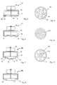
- FIG. 4a shows a longitudinal section
- FIG. 4b a plan view of a vortex attractor 10 having only an impeller 12 in its housing 30, the motor 20 above the housing 30 axially offset and is preferably arranged concentrically with the impeller 12.
- the housing 30 is formed cylindrical and closed to one side, while the other side is formed open and the suction port 4 forms.
- a first friction element 40 is arranged, which is formed from a plurality of annular segment-shaped sections 42 of a plurality of concentrically arranged rings.
- FIG. 5 shows a longitudinal section through the vortex attractor 10 with a second friction element 50, which has a peripheral edge of the suction opening 4 circumferential annular member 52 and a concentric, preferably in the same plane, arranged round element 54.
- FIG. 6 shows a longitudinal section through the vortex attractor 10 with a third friction element 60, which has a three-dimensional structure.
- the friction element 60 is in particular wave-shaped and has, for example, concentrically arranged waves.
- the amplitude of the waves in this case runs in particular parallel to the axis of rotation R of the impeller 12.
- FIG. 7 shows a longitudinal section through the vortex attractor 10 with a fourth friction element 70, which also has a three-dimensional structure.
- the fourth friction element 70 has a circumferential ring 72 arranged at the edge of the suction opening 4 and a further annular element 74 with an outer diameter which is smaller than the inner diameter of the annular element 72 but with an inner diameter which is greater than the inner diameter of the annular one Element 72, and a round member 76 having an outside diameter which is larger than the inside diameter of the annular member 74.
- the round member 76 and the annular members 74, 72 are associated coaxially with one another such that the annular member 74 is axially offset the annular member 72 and axially offset from the round member 76 between the round member 76 and the annular member 72 is arranged.
- FIG. 8 shows a longitudinal section through the vortex attractor 10 with a fifth friction element 80, which has an edge of the suction opening 40 arranged annular member 82 and an axially offset therefrom round element 84, wherein the outer diameter of the round element is greater than the inner diameter of the annular Elements and thus the annular element 82 and the round element 84 are arranged overlapping each other in the radial direction.
- FIG. 9 shows the top view of a sixth friction element 90, which in a round cover a round centrically arranged recess 92 and six congruent, limited by two secants through the suction port 4 and a circular arc segment about the rotation axis, formed in the edge region of the cover recesses 94.
- FIG. 10 shows the top view of a seventh friction element 100, which is formed as a spiral winding. This may be in the plane of the suction opening 4, in front of or behind it, or may be formed in three dimensions.
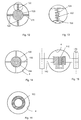
- FIG. 11 shows the top view of an eighth friction element 110, which has two radially extending webs 112 interconnected annular elements 114, 116.
- FIG. 12 shows the top view of a ninth friction element 120, which is designed as centrally arranged in the suction port 4 element which is connected via a plurality of resilient elements 122 with the edge of the suction port 4.
- the resilient elements 122 may, as in FIG. 13 shown additionally having a damping element 124.
- FIG. 14 shows a plan view of a tenth friction element 130 which is formed as a spiral spring, which is arranged centrally in, behind or in front of the suction opening 4 and may be arranged, for example, with the outer winding at the edge of the suction opening 4 or, as in FIG. 14 shown with the outer winding in a via webs 132 with the edge of the
- Suction opening 4 connected annular element 134 may be arranged.
- FIG. 15 shows an eleventh friction element 140, which is slidably mounted on a arranged upstream of the suction port 4 rod 142, by which, for example, offset the object held on the suction port 4 relative to the suction port 4 can be compensated.
- FIG. 16 shows a plan view of a twelfth friction element 150, which is arranged as an annular element in front of or in the suction opening 4, for example by means of webs or the like.
- FIG. 26 shows a longitudinal section through a vortex attractor 10, in which the wings 14 of the impeller 12 to the suction port 4 tapers and, for example, a convex geometry is formed in longitudinal section.
- a thirteenth friction element 160 is arranged, which has a three-dimensional structure in the form of nubs 162.
- the friction elements 40, 50, 60, 70, 80, 90, 100, 110, 120, 130, 140, 150, 160 should preferably be designed such that they cover less than 60% of the area of the suction opening 4, to the by first means for generating a whirlwind, which are formed in particular as an impeller 12, negative pressure generated as little as possible.
- the friction elements 40, 50, 60, 70, 80, 90, 100, 110, 120, 130, 140, 150, 160 have a height which should advantageously be less than 4% of the diameter of the suction opening 4, in order by the Impeller 12 produced negative pressure as little as possible.
- All of the friction elements 40, 50, 60, 70, 80, 90, 100, 110, 120, 130, 140, 150, 160 are intended to create a large frictional force between them and the object held by the vortex attractor 10.
- the friction elements 40, 50, 60, 70, 80, 90, 100, 110, 120, 130, 140, 150, 160 for example, formed elastically, in particular made of rubber, have a rough or textured surface, for example in the form of Structural elements such as ribs, dents and / or nubs, or may have three-dimensional structures.
- the structures may in particular be arranged in a grid or geometrically regularly.
- the friction elements 40, 50, 60, 70, 80, 90, 100, 110, 120, 130, 140, 150, 160 may be formed as a grid or wave-shaped structures.
- the friction elements 40, 50, 60, 70, 80, 90, 100, 110, 120, 130, 140, 150, 160 have a perforated surface or be made of an air-permeable material.
- Each of the friction elements 40, 50, 60, 70, 80, 90, 100, 110, 120, 130, 140, 150, 160 may be variably arranged in its axial distance to the plane of the suction opening 4 or at least comprise an element which in its axial distance from the plane of the suction opening 4 is configured variable.
- each of these devices 10 may include one or more of the previously described friction elements 40, 50, 60, 70, 80, 90, 100, 110, 120, 130, 140, 150, 160.
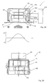
- FIG. 17 shows an embodiment of the vortex attractor 10, which has a housing 30 with a rear wall 30b, wherein in the rear wall 30b, a recess 30c is arranged, in which the motor 20 is inserted.
- the housing 30 is movable relative to the wings 14 of the impeller 12 by means of a spindle drive 31 along a shaft S, in particular by means of a further motor 33, which may be formed as a stepping motor.
- FIG. 17 shows a vortex attractor 10 with the housing 30 in such a position in which the housing 30 surrounds the wings 14 of the impeller 12.
- FIG. 18 shows the vortex attractor 10 according to FIG. 17 in which the housing 30 has been moved upwards along the shaft S, so that the housing 30 is arranged axially over the blades 14 of the impeller 12.
- the direction and the absolute intensity of the negative pressure of the vortex attractor 10 can be varied, as in particular FIG. 19 recognizable in which the curve denoted by b the negative pressure of the vortex attractor 10 with the housing 30 in the pushed-up position (see FIG. 18 ), while the curve labeled a represents the negative pressure of the vortex attractor 10 with the housing 30 in the retracted position (see FIG. 17).
- FIGS. 20 to 22 another embodiment of a vortex attractor 10 is shown, which has second means to vary the intensity of the negative pressure can.
- the vortex attractor 10 has an iris diaphragm 34, which is arranged in front of the suction opening 4 of the vortex attractor 10 is.
- the iris diaphragm 34 can be opened and closed by means of a lever 34a, wherein the lever 34a can be actuated either manually or by means of a motor.
- FIG. 21a is a plan view of the vortex attractor 10 according to FIG. 20a with the iris diaphragm 34 closed.
- FIG. 21b shows the iris 34 in partially open position and
- FIG. 21c shows the iris 34 in the open position.
- FIG. 22a, 22b and 22c show that by the vortex attractor 10 according to FIG. 20a generated negative pressure at the various positions of the iris diaphragm 34 as in Figures 21a, 21b and 21c shown.
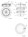
- FIGS. 23a, 23b and 23c show a further possibility to design the vacuum generated in front of the suction opening 4 variable.
- two aperture elements 35 are arranged in front of the suction opening 4 about a common axis of rotation, which in particular coincides with the axis of rotation of the cyclone, rotatable in front of the suction opening 4.
- the diaphragm elements 35 have open areas 35a and closed areas 35b, which in the present case are in particular circular-segment-shaped and are arranged alternately at the same angular distance from each other.
- FIG. 23a shows the two diaphragm elements 35 in such a relative arrangement, in which the closed areas 35b are arranged directly above one another and, accordingly, the open areas 35a are also arranged directly above one another.
- the suction opening 4 is open as far as possible.
- the two aperture elements 35 are rotated against each other.
- the closed areas 35b of the one shutter member 35 partially cover the opened portions 35a of the other shutter member 35 and vice versa, so that the opened area in front of the suction port 4 is reduced.
- the two diaphragm elements 35 are arranged relative to one another such that the closed regions 35b cover the open regions 35a of the respective other diaphragm element 35, so that the suction opening 4 is completely closed. In this way, the negative pressure generated in front of the suction opening 4 can be varied.
- FIGS. 24a, 24b and 25 Another possibility for varying the negative pressure in front of the suction opening 4 is shown.
- a diaphragm element 36 as in FIG. 25 shown arranged in front of the suction opening 4.
- the diaphragm element 36 is arranged in its axial position displaceable in front of the suction opening 4.
- the axial displacement is accomplished by pulling apart two elements coupled together by a gear, whereby the element 36 is moved axially and the air flow can pass only through the element 36 instead of around the element 36, whereby the negative pressure created in front of the suction opening 4 is designed variable.
- FIGS. 27a to 27e show another possibility for varying the negative pressure in front of the suction opening 4. Similar to that in the FIGS. 23a to 23c illustrated embodiments, two aperture elements 37, 38 are arranged rotatable about a common axis of rotation to each other in front of the suction opening 4.
- the diaphragm element 38 corresponds to the diaphragm element 35 in accordance with FIG. 23a and has open areas 38a and closed areas 38b, which are formed substantially circular segment and alternately at the same angular distance from each other.
- the diaphragm element 37 has in one circular inner portion 37a, whose radius is smaller than the radius of the diaphragm member 37, an analogous configuration with open Bhus 37b and closed areas 37c, which are formed in a circle segment and alternately at the same angular distance from each other.
- closed regions 37e and open regions 37f alternate at equal angular spacing from each other, but in the annular segment of the annular region 37d, in which a closed region 37c is arranged in the inner region 37a, an open area 37f is arranged in the annular area 37d, while in the ring segments of the annular area 37d, in which an open area 37b is arranged in the inner area 37a, a closed area 37e is arranged in the outer annular area 37d.
- the two diaphragm elements 37 and 38 are rotatable relative to each other.
- one of the two diaphragm elements 37, 38 for example the diaphragm element 37, can be arranged rigidly in front of the suction opening 4.
- the closed portions 38b of the shutter member 38 come to rest in front of the opened portions 37b of the inner portion 37a of the shutter member 37 so that the surface of the inner portion 37a in front of the suction port 4 is completely closed (see Figure 27c ), while the closed areas 38b of the diaphragm element 38 in the outer annular area 37d coincide with the closed areas 37e of the diaphragm element 37, so that open and closed areas in the outer annular area 37d alternate in front of the suction opening 4 (see FIG Figure 27c ).
- the closed portions 38b of the shutter member 38 coincide with the opened surfaces 37f of the outer annular portion 37d of the shutter member 37, while the opened portions 38a of the shutter member 38 are aligned with the opened portions 37b of the inner portion 37a of the shutter member 37 so that the surface in the outer annular portion 37d in front of the suction port 4 is completely closed, while in the inner portion 37a of the shutter member 37 in front of the suction port 4 opened with closed portions alternate.
- the negative pressure upstream of the suction opening 4 can already be varied in this way, since the open or closed portion of the surface of the suction opening 4 varies.
- This aperture structure is particularly preferred in combination with the following with reference to FIG. 28 described device 1 is used.
- FIG. 28 schematically shows a device 1 with first means 2 for generating a negative pressure, which is designed in particular as a vortex attractor 10 according to one of the embodiments described above.
- the vortex attractor 10 is arranged in particular in the housing 30, which is closed at the top, wherein the motor 20 is disposed within the housing 30 axially above the impeller 12.
- the motor 20 is arranged in particular on the suction opening 4 opposite side of the impeller 12.
- the suction opening 4 facing away from the wall of the housing 30 forms a partition wall to a second impeller 170, which is driven by a motor 172.
- the motor 172 and the second impeller 170 are arranged axially to each other, wherein the motor 172 is disposed adjacent to the rear wall of the housing 30.
- the second impeller 170 and the motor 172 are arranged in a housing 174, which is formed substantially cylindrical and is preferably aligned coaxially with the likewise cylindrical housing 30.
- the housing 174 has a larger diameter than the housing 30.
- the second impeller 170 has similar dimensions
- the second impeller 170 thus generates an air flow which exits laterally from the second impeller 170 and exits concentrically around the suction opening 4 through the annular volume between the outer wall of the housing 30 and the inner wall of the housing 174 and constitutes a blowing wind , which counteracts the attractive force of the whirlwind generated by the impeller 12.
- a regulator 176 may be provided for controlling the impellers 12, 170.
- the strength of the negative pressure of the impeller 12 and the repulsive force of the impeller of the second impeller 170 can, as described above, by means of the apertures 37 and 38, in the Figures 27a and 27b are also varied.
- the negative pressure of the impeller 12 generated in front of the suction opening 4 is also variable when means are provided to influence the rotational speed of the impeller 12 and, for example, to stop the impeller 12 instantaneously.
- An embodiment of such a vortex attractor 10 is shown in FIG FIG. 29 shown.
- the impeller 12 In the housing 30, in which the impeller 12 is arranged, which is driven by the arranged outside the housing 30 motor 20, axially spaced at a distance d and with the same axis of rotation another impeller 180 is arranged, which is not driven by a motor , but only by the whirlwind generated by the impeller 12 is driven.
- the rotational speed of the impeller 180 is dependent on the distance d between the impeller 12 and the impeller 180.
- the impeller 180 includes an electromagnetic brake 182, with which the rotational movement of the impeller 180 can be instantaneously stopped, which also leads to an instantaneous stop the rotational movement of the impeller 12 and an abrupt termination of the attraction of the vortex attractor 10.
- FIGS. 30a to 30c An alternative embodiment to that in FIG. 28 shown device 1, which can produce both an attractive force and a repulsive force is in the FIGS. 30a to 30c shown.
- This device 1 has only an impeller 12, which is arranged in a housing 30, in whose side wall openings are arranged, which can be at least partially closed.
- the housing 30 in one embodiment has two mutually rotatable housing parts 190, 192 which circumferentially openings 191, 193 which can be aligned either in a relative position with each other or cover each other in a different relative position. If the openings 191, 193 cover each other, the housing 30 is substantially closed and the impeller 12 creates a whirlwind with maximum attractive force in front of the suction opening 4.
- the housing 30 has openings in the side walls the air flow generated by the impeller 12 can pass outwardly through the housing 30, where it is deflected towards the suction opening 4 by an outer housing 194, which is arranged substantially concentric with the housing 30 and open towards the suction opening 4 is, but now acts as a blowing wind and counteracts the vacuum generated by the impeller 12.
- the orientation of the two housing parts 190, 192 can be operated by means of a lever 196 manually or by motor control.
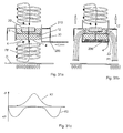
- FIGS Figures 31a to 31c A further alternative embodiment of a vortex attractor 10 with second means for varying the negative pressure generated by the impeller 12 is shown in FIGS Figures 31a to 31c shown.
- the suction opening 4 of the vortex attractor 10 can be covered by means of a slider 200.
- FIG. 31a shows the slider 200 in the open position, in which a whirlwind FF is generated by the impeller 12, which attracts the object O.
- FIG. 31b the slider 200 is closed.
- FIG. 31c shows in the graph K1 the pressure exerted on the object O with the slider 200 open, as in FIG. 31a while the graph K2 shows the pressure applied to the object O with the slider 200 closed, as in FIG. 31b shown, shows.
Landscapes
- Engineering & Computer Science (AREA)
- Mechanical Engineering (AREA)
- Robotics (AREA)
- Structures Of Non-Positive Displacement Pumps (AREA)
- Load-Engaging Elements For Cranes (AREA)
- Specific Conveyance Elements (AREA)
- Hooks, Suction Cups, And Attachment By Adhesive Means (AREA)
Claims (7)
- Dispositif de levage et de positionnement d'un objet comprenant des premiers moyens permettant d'obtenir une dépression au moyen d'un tourbillon pour permettre d'aspirer l'objet, dans lequel les premiers moyens sont logés à la partie interne d'un boîtier qui comporte une ouverture d'aspiration, le tourbillon produisant une dépression à l'avant de l'ouverture d'aspiration, et le dispositif comprenant des seconds moyens permettant de faire varier la dépression à l'avant de l'ouverture d'aspiration,
caractérisé en ce que
les seconds moyens sont réalisés sous la forme d'éléments de freinage des premiers moyens. - Dispositif conforme à la revendication 1,
caractérisé en ce que
les seconds moyens sont réalisés sous la forme de freins électromagnétiques. - Dispositif conforme à l'une des revendications 1 et 2,
caractérisé en ce que
les premiers moyens sont réalisés sous la forme d'un premier rotor tandis que les seconds moyens sont réalisés sous la forme d'un second rotor, le second rotor étant monté co-axialement au premier rotor, le premier rotor étant entraîné par un moteur et le second rotor comprenant un frein électromagnétique. - Dispositif conforme à l'une des revendications 1 à 3,
caractérisé en ce que
les premiers moyens et les seconds moyens sont réalisés sous la forme d'un premier et d'un second rotors, le second rotor étant monté co-axialement au premier rotor sur la face du premier rotor située à l'opposé de l'ouverture d'aspiration, une paroi de séparation étant positionnée entre le premier rotor et le second rotor, autour du second rotor étant monté un boîtier qui est concentrique au boîtier du premier rotor, et a un plus grand diamètre que le diamètre du premier rotor. - Dispositif conforme à l'une des revendications précédentes, caractérisé en ce que
les premiers moyens sont réalisés sous la forme d'un premier rotor. - Dispositif conforme à l'une des revendications précédentes, caractérisé en ce que
le rotor comprend une roue de rotor et un boîtier de rotor, la roue de rotor étant mobile par rapport au boîtier de rotor dans la direction de l'axe de rotation. - Dispositif conforme à l'une des revendications précédentes, caractérisé en ce qu'
il est prévu un régulateur pour permettre de régler les premiers moyens et/ou les seconds moyens, de préférence pour permettre de régler, brancher, débrancher, ralentir et/ou accélérer les premiers moyens et/ou les seconds moyens de préférence lorsque les premiers moyens et/ou les seconds moyens sont réalisés sous la forme d'un rotor.
Applications Claiming Priority (2)
| Application Number | Priority Date | Filing Date | Title |
|---|---|---|---|
| DE202011107531U DE202011107531U1 (de) | 2011-11-07 | 2011-11-07 | Vorrichtung zum Heben und Positionieren eines Objekts |
| EP12787408.9A EP2776358B1 (fr) | 2011-11-07 | 2012-11-05 | Dispositif pour soulever et positionner un objet |
Related Parent Applications (2)
| Application Number | Title | Priority Date | Filing Date |
|---|---|---|---|
| EP12787408.9A Division EP2776358B1 (fr) | 2011-11-07 | 2012-11-05 | Dispositif pour soulever et positionner un objet |
| EP12787408.9A Division-Into EP2776358B1 (fr) | 2011-11-07 | 2012-11-05 | Dispositif pour soulever et positionner un objet |
Publications (2)
| Publication Number | Publication Date |
|---|---|
| EP2799385A1 EP2799385A1 (fr) | 2014-11-05 |
| EP2799385B1 true EP2799385B1 (fr) | 2016-06-29 |
Family
ID=45495484
Family Applications (2)
| Application Number | Title | Priority Date | Filing Date |
|---|---|---|---|
| EP12787408.9A Active EP2776358B1 (fr) | 2011-11-07 | 2012-11-05 | Dispositif pour soulever et positionner un objet |
| EP14172827.9A Active EP2799385B1 (fr) | 2011-11-07 | 2012-11-05 | Dispositif de levage et de positionnement d'un objet |
Family Applications Before (1)
| Application Number | Title | Priority Date | Filing Date |
|---|---|---|---|
| EP12787408.9A Active EP2776358B1 (fr) | 2011-11-07 | 2012-11-05 | Dispositif pour soulever et positionner un objet |
Country Status (7)
| Country | Link |
|---|---|
| US (1) | US9339936B2 (fr) |
| EP (2) | EP2776358B1 (fr) |
| JP (1) | JP6105610B2 (fr) |
| CN (1) | CN103974894B (fr) |
| DE (1) | DE202011107531U1 (fr) |
| ES (1) | ES2593257T3 (fr) |
| WO (1) | WO2013068307A1 (fr) |
Families Citing this family (12)
| Publication number | Priority date | Publication date | Assignee | Title |
|---|---|---|---|---|
| US20110287297A1 (en) * | 2009-12-11 | 2011-11-24 | Toshitada Sato | Nonaqueous electrolyte secondary battery |
| DE102015200170B4 (de) * | 2014-02-10 | 2023-08-03 | Heidelberger Druckmaschinen Ag | Vorrichtung zum Ansaugen eines Bogens von einem Bogenstapel |
| DE102015221822B4 (de) | 2014-12-11 | 2025-10-02 | Heidelberger Druckmaschinen Ag | Vorrichtung zum Halten von Bögen mittels Saugluft |
| JP6701758B2 (ja) | 2016-01-25 | 2020-05-27 | 株式会社リコー | 供給装置、画像形成システム、被搬送物検査システム |
| EP3243608B1 (fr) * | 2016-05-09 | 2022-04-06 | J. Schmalz GmbH | Procede de surveillance des etats de fonctionnement d'un actionneur commande par pression et actionneur commande par pression |
| US11097524B2 (en) * | 2017-05-26 | 2021-08-24 | The Boeing Company | Flexible vacuum securement of objects to complex surfaces |
| DE102018120155B4 (de) * | 2018-08-20 | 2021-04-22 | J. Schmalz Gmbh | Sauggreifer mit variabler Saugfläche |
| CN109051790B (zh) * | 2018-10-17 | 2020-04-17 | 大江南电子科技(昆山)有限公司 | 斜立式收放板机的真空吸板机构 |
| CN111170001B (zh) * | 2020-02-18 | 2025-01-03 | 浙江大学 | 转盘机构 |
| US11351678B1 (en) * | 2020-03-10 | 2022-06-07 | Amazon Technologies, Inc. | Dynamically adjustable suction cups |
| CN113998462B (zh) * | 2021-12-28 | 2022-05-03 | 三一技术装备有限公司 | 极片输送装置及叠片机 |
| US12001229B1 (en) * | 2023-11-20 | 2024-06-04 | Juan Carlos G. de Ledebur | Pneumatic elevator with pressure regulator |
Family Cites Families (29)
| Publication number | Priority date | Publication date | Assignee | Title |
|---|---|---|---|---|
| US192070A (en) * | 1877-06-19 | Improvement in furnace-grates | ||
| GB966957A (en) * | 1963-02-18 | 1964-08-19 | F L Smidth & Company As | Improvements in and relating to the handling of fibrous cement sheets |
| US3796455A (en) * | 1972-09-05 | 1974-03-12 | Unimation Inc | Air flow actuated overhead pickup device for limp sheet materials |
| DE2330204A1 (de) * | 1973-06-14 | 1975-01-09 | Thermak Gmbh & Co Kg | Foerdervorrichtung fuer plattenfoermiges gut |
| FR2495592A1 (fr) * | 1980-12-05 | 1982-06-11 | Joulin Sema | Dispositif de prehension fonctionnant par succion |
| CN2036940U (zh) * | 1988-09-29 | 1989-05-03 | 夏永泽 | 真空吸坯机 |
| JP2524586Y2 (ja) * | 1990-09-06 | 1997-02-05 | エスエムシー株式会社 | 吸着用パッド |
| FR2709478B3 (fr) | 1993-08-30 | 1996-06-14 | Joulin Aero Distribution | Dispositif de préhension et/ou de transport de matériaux. |
| JPH0994786A (ja) * | 1995-10-02 | 1997-04-08 | Hitachi Seiki Co Ltd | 吸着搬送装置 |
| WO1997045862A1 (fr) * | 1996-05-31 | 1997-12-04 | Ipec Precision, Inc. | Support sans contact pour des articles en forme de plaquette |
| US6095582A (en) * | 1998-03-11 | 2000-08-01 | Trusi Technologies, Llc | Article holders and holding methods |
| US6131973A (en) * | 1998-10-01 | 2000-10-17 | Sikorsky Aircraft Corporation | Vacuum transfer device |
| US6254155B1 (en) * | 1999-01-11 | 2001-07-03 | Strasbaugh, Inc. | Apparatus and method for reliably releasing wet, thin wafers |
| US6619922B2 (en) * | 1999-05-21 | 2003-09-16 | Vortex Holding Company | Vortex attractor for planar and non-planar surfaces |
| US6565321B1 (en) | 1999-05-21 | 2003-05-20 | Vortex Holding Company | Vortex attractor |
| JP4547649B2 (ja) * | 2000-07-31 | 2010-09-22 | Smc株式会社 | 吸着用パッド |
| US7204672B2 (en) * | 2002-12-09 | 2007-04-17 | Anemoid, Llc | Multi-modal forced vortex device |
| DE10304169B4 (de) * | 2003-01-29 | 2006-02-23 | J. Schmalz Gmbh | Sauggreifer |
| US20040212205A1 (en) * | 2003-01-30 | 2004-10-28 | Linker Frank V. | Method and apparatus for handling semiconductor wafers and interleafs |
| DK176329B1 (da) * | 2004-09-09 | 2007-08-13 | Lina Medical Aps | Obstetisk vakuumkop |
| US8079494B2 (en) * | 2006-10-24 | 2011-12-20 | Tandem Technologies, Llc | Delivery system |
| JP2008290170A (ja) * | 2007-05-23 | 2008-12-04 | Renesas Technology Corp | 半導体装置の製造方法 |
| US20090097953A1 (en) * | 2007-10-12 | 2009-04-16 | R.A. Jones & Co., Inc. | Device for moving packages and methods of using the same |
| DE202008010424U1 (de) * | 2008-07-30 | 2009-12-24 | J. Schmalz Gmbh | Mit Druckluft betriebener Flächensauggreifer |
| US8800753B2 (en) | 2009-09-10 | 2014-08-12 | Bdt Media Automation Gmbh | System for conveying an article using vortex suction units |
| DE102010000526A1 (de) * | 2010-02-24 | 2011-08-25 | Krones Ag, 93073 | Unterdruck-Greifervorrichtung |
| US9079733B2 (en) | 2010-05-07 | 2015-07-14 | Bdt Media Automation Gmbh | Vortex suction separator device |
| CN201770398U (zh) * | 2010-05-13 | 2011-03-23 | 宋矿复 | 一种真空吸盘装置 |
| US8186668B2 (en) | 2010-10-07 | 2012-05-29 | Bdt Ag | Stack feeding aeration device and method |
-
2011
- 2011-11-07 DE DE202011107531U patent/DE202011107531U1/de not_active Expired - Lifetime
-
2012
- 2012-11-05 US US14/356,612 patent/US9339936B2/en active Active
- 2012-11-05 JP JP2014539353A patent/JP6105610B2/ja active Active
- 2012-11-05 WO PCT/EP2012/071791 patent/WO2013068307A1/fr not_active Ceased
- 2012-11-05 CN CN201280060506.0A patent/CN103974894B/zh active Active
- 2012-11-05 EP EP12787408.9A patent/EP2776358B1/fr active Active
- 2012-11-05 EP EP14172827.9A patent/EP2799385B1/fr active Active
- 2012-11-05 ES ES12787408.9T patent/ES2593257T3/es active Active
Also Published As
| Publication number | Publication date |
|---|---|
| CN103974894B (zh) | 2016-02-03 |
| JP2015502304A (ja) | 2015-01-22 |
| EP2799385A1 (fr) | 2014-11-05 |
| DE202011107531U1 (de) | 2011-12-15 |
| US20150061309A1 (en) | 2015-03-05 |
| EP2776358A1 (fr) | 2014-09-17 |
| JP6105610B2 (ja) | 2017-03-29 |
| WO2013068307A1 (fr) | 2013-05-16 |
| US9339936B2 (en) | 2016-05-17 |
| ES2593257T3 (es) | 2016-12-07 |
| EP2776358B1 (fr) | 2016-05-11 |
| CN103974894A (zh) | 2014-08-06 |
Similar Documents
| Publication | Publication Date | Title |
|---|---|---|
| EP2799385B1 (fr) | Dispositif de levage et de positionnement d'un objet | |
| DE112015003481B4 (de) | Vorrichtung zum Abscheiden von Öltröpfchen und/oder Ölnebel | |
| DE102007035759B4 (de) | Schlagflügelanordnung | |
| EP3795836A1 (fr) | Pompe centrifuge et carter de pompe | |
| CH706373A1 (de) | Saugpumpeneinheit. | |
| WO2014090580A1 (fr) | Machine à rotation électrique | |
| EP1320407B1 (fr) | Aeronef telecommandable | |
| EP2683608B1 (fr) | Dispositif à aile battante et procédé permettant de faire fonctionner un dispositif à aile battante | |
| DE602005004737T2 (de) | Leitschaufelstufe eines Leitapparates die von einen drehbaren Ring angetrieben wird wobei der Ring von Elektromotoren versetzt wird | |
| DE112017008056T5 (de) | Rotor- oder propellerblatt mit innerhalb jeder umdrehung dynamisch optimierbarer form sowie weiteren eigenschaften | |
| WO2017137472A1 (fr) | Dispositif de séparation de cellules et utilisation d'une formation d'écoulement à destination du dispositif de séparation de cellules | |
| DE102010012203A1 (de) | Gelenkdüsensystem | |
| DE102011122140A1 (de) | Delta-Wirbelstromgeneratoren | |
| DE102008022452A1 (de) | Flugzeug mit aktiv steuerbaren Hilfsflügeln | |
| DE202007018525U1 (de) | Schlagflügelanordnung | |
| DE102007035760B4 (de) | Schlagflügelanordnung | |
| EP2055963A2 (fr) | Ventilateur doté d'ailettes | |
| DE10125734B4 (de) | Fernsteuerbares Fluggerät | |
| EP3601799A1 (fr) | Soupape de compresseur à piston et son procédé de fonctionnement | |
| WO2015150411A1 (fr) | Accouplement magnétique, dispositif d'accouplement, et procédé correspondant | |
| DE102007046373A1 (de) | Staubsauger mit einer Vorrichtung zur Regulierung des Luftdurchsatzes stromaufwärts des Motors | |
| EP4655050A1 (fr) | Roue de pompe et pompe | |
| DE202025106192U1 (de) | Antriebsvorrichtung für Luftfahrzeuge | |
| DE102024125809A1 (de) | Luftausströmvorrichtung für ein Kraftfahrzeug, Innenverkleidung für ein Kraftfahrzeug und Verfahren zum Betreiben einer Luftausströmvorrichtung | |
| EP3601798A1 (fr) | Obturateur pour une soupape de compresseur à piston et procédé de fonctionnement de l'obturateur de soupape |
Legal Events
| Date | Code | Title | Description |
|---|---|---|---|
| PUAI | Public reference made under article 153(3) epc to a published international application that has entered the european phase |
Free format text: ORIGINAL CODE: 0009012 |
|
| 17P | Request for examination filed |
Effective date: 20140617 |
|
| AC | Divisional application: reference to earlier application |
Ref document number: 2776358 Country of ref document: EP Kind code of ref document: P |
|
| AK | Designated contracting states |
Kind code of ref document: A1 Designated state(s): AL AT BE BG CH CY CZ DE DK EE ES FI FR GB GR HR HU IE IS IT LI LT LU LV MC MK MT NL NO PL PT RO RS SE SI SK SM TR |
|
| AX | Request for extension of the european patent |
Extension state: BA ME |
|
| R17P | Request for examination filed (corrected) |
Effective date: 20150430 |
|
| RBV | Designated contracting states (corrected) |
Designated state(s): AL AT BE BG CH CY CZ DE DK EE ES FI FR GB GR HR HU IE IS IT LI LT LU LV MC MK MT NL NO PL PT RO RS SE SI SK SM TR |
|
| RIC1 | Information provided on ipc code assigned before grant |
Ipc: B65G 47/91 20060101ALI20151113BHEP Ipc: B65H 3/08 20060101ALI20151113BHEP Ipc: B25J 15/06 20060101ALI20151113BHEP Ipc: B66C 1/02 20060101AFI20151113BHEP |
|
| GRAP | Despatch of communication of intention to grant a patent |
Free format text: ORIGINAL CODE: EPIDOSNIGR1 |
|
| INTG | Intention to grant announced |
Effective date: 20160219 |
|
| GRAS | Grant fee paid |
Free format text: ORIGINAL CODE: EPIDOSNIGR3 |
|
| GRAA | (expected) grant |
Free format text: ORIGINAL CODE: 0009210 |
|
| AC | Divisional application: reference to earlier application |
Ref document number: 2776358 Country of ref document: EP Kind code of ref document: P |
|
| AK | Designated contracting states |
Kind code of ref document: B1 Designated state(s): AL AT BE BG CH CY CZ DE DK EE ES FI FR GB GR HR HU IE IS IT LI LT LU LV MC MK MT NL NO PL PT RO RS SE SI SK SM TR |
|
| REG | Reference to a national code |
Ref country code: GB Ref legal event code: FG4D Free format text: NOT ENGLISH |
|
| REG | Reference to a national code |
Ref country code: CH Ref legal event code: EP |
|
| REG | Reference to a national code |
Ref country code: AT Ref legal event code: REF Ref document number: 808934 Country of ref document: AT Kind code of ref document: T Effective date: 20160715 |
|
| REG | Reference to a national code |
Ref country code: IE Ref legal event code: FG4D Free format text: LANGUAGE OF EP DOCUMENT: GERMAN |
|
| REG | Reference to a national code |
Ref country code: CH Ref legal event code: NV Representative=s name: R.A. EGLI AND CO, PATENTANWAELTE, CH |
|
| REG | Reference to a national code |
Ref country code: DE Ref legal event code: R096 Ref document number: 502012007544 Country of ref document: DE |
|
| REG | Reference to a national code |
Ref country code: LT Ref legal event code: MG4D |
|
| PG25 | Lapsed in a contracting state [announced via postgrant information from national office to epo] |
Ref country code: NO Free format text: LAPSE BECAUSE OF FAILURE TO SUBMIT A TRANSLATION OF THE DESCRIPTION OR TO PAY THE FEE WITHIN THE PRESCRIBED TIME-LIMIT Effective date: 20160929 Ref country code: FI Free format text: LAPSE BECAUSE OF FAILURE TO SUBMIT A TRANSLATION OF THE DESCRIPTION OR TO PAY THE FEE WITHIN THE PRESCRIBED TIME-LIMIT Effective date: 20160629 Ref country code: LT Free format text: LAPSE BECAUSE OF FAILURE TO SUBMIT A TRANSLATION OF THE DESCRIPTION OR TO PAY THE FEE WITHIN THE PRESCRIBED TIME-LIMIT Effective date: 20160629 |
|
| REG | Reference to a national code |
Ref country code: NL Ref legal event code: MP Effective date: 20160629 |
|
| REG | Reference to a national code |
Ref country code: FR Ref legal event code: PLFP Year of fee payment: 5 |
|
| PG25 | Lapsed in a contracting state [announced via postgrant information from national office to epo] |
Ref country code: GR Free format text: LAPSE BECAUSE OF FAILURE TO SUBMIT A TRANSLATION OF THE DESCRIPTION OR TO PAY THE FEE WITHIN THE PRESCRIBED TIME-LIMIT Effective date: 20160930 Ref country code: SE Free format text: LAPSE BECAUSE OF FAILURE TO SUBMIT A TRANSLATION OF THE DESCRIPTION OR TO PAY THE FEE WITHIN THE PRESCRIBED TIME-LIMIT Effective date: 20160629 Ref country code: LV Free format text: LAPSE BECAUSE OF FAILURE TO SUBMIT A TRANSLATION OF THE DESCRIPTION OR TO PAY THE FEE WITHIN THE PRESCRIBED TIME-LIMIT Effective date: 20160629 Ref country code: RS Free format text: LAPSE BECAUSE OF FAILURE TO SUBMIT A TRANSLATION OF THE DESCRIPTION OR TO PAY THE FEE WITHIN THE PRESCRIBED TIME-LIMIT Effective date: 20160629 Ref country code: HR Free format text: LAPSE BECAUSE OF FAILURE TO SUBMIT A TRANSLATION OF THE DESCRIPTION OR TO PAY THE FEE WITHIN THE PRESCRIBED TIME-LIMIT Effective date: 20160629 Ref country code: NL Free format text: LAPSE BECAUSE OF FAILURE TO SUBMIT A TRANSLATION OF THE DESCRIPTION OR TO PAY THE FEE WITHIN THE PRESCRIBED TIME-LIMIT Effective date: 20160629 |
|
| PG25 | Lapsed in a contracting state [announced via postgrant information from national office to epo] |
Ref country code: RO Free format text: LAPSE BECAUSE OF FAILURE TO SUBMIT A TRANSLATION OF THE DESCRIPTION OR TO PAY THE FEE WITHIN THE PRESCRIBED TIME-LIMIT Effective date: 20160629 Ref country code: IT Free format text: LAPSE BECAUSE OF FAILURE TO SUBMIT A TRANSLATION OF THE DESCRIPTION OR TO PAY THE FEE WITHIN THE PRESCRIBED TIME-LIMIT Effective date: 20160629 Ref country code: EE Free format text: LAPSE BECAUSE OF FAILURE TO SUBMIT A TRANSLATION OF THE DESCRIPTION OR TO PAY THE FEE WITHIN THE PRESCRIBED TIME-LIMIT Effective date: 20160629 Ref country code: SK Free format text: LAPSE BECAUSE OF FAILURE TO SUBMIT A TRANSLATION OF THE DESCRIPTION OR TO PAY THE FEE WITHIN THE PRESCRIBED TIME-LIMIT Effective date: 20160629 Ref country code: IS Free format text: LAPSE BECAUSE OF FAILURE TO SUBMIT A TRANSLATION OF THE DESCRIPTION OR TO PAY THE FEE WITHIN THE PRESCRIBED TIME-LIMIT Effective date: 20161029 Ref country code: CZ Free format text: LAPSE BECAUSE OF FAILURE TO SUBMIT A TRANSLATION OF THE DESCRIPTION OR TO PAY THE FEE WITHIN THE PRESCRIBED TIME-LIMIT Effective date: 20160629 |
|
| PGFP | Annual fee paid to national office [announced via postgrant information from national office to epo] |
Ref country code: NL Payment date: 20161125 Year of fee payment: 5 |
|
| PG25 | Lapsed in a contracting state [announced via postgrant information from national office to epo] |
Ref country code: PL Free format text: LAPSE BECAUSE OF FAILURE TO SUBMIT A TRANSLATION OF THE DESCRIPTION OR TO PAY THE FEE WITHIN THE PRESCRIBED TIME-LIMIT Effective date: 20160629 Ref country code: PT Free format text: LAPSE BECAUSE OF FAILURE TO SUBMIT A TRANSLATION OF THE DESCRIPTION OR TO PAY THE FEE WITHIN THE PRESCRIBED TIME-LIMIT Effective date: 20161031 Ref country code: SM Free format text: LAPSE BECAUSE OF FAILURE TO SUBMIT A TRANSLATION OF THE DESCRIPTION OR TO PAY THE FEE WITHIN THE PRESCRIBED TIME-LIMIT Effective date: 20160629 Ref country code: ES Free format text: LAPSE BECAUSE OF FAILURE TO SUBMIT A TRANSLATION OF THE DESCRIPTION OR TO PAY THE FEE WITHIN THE PRESCRIBED TIME-LIMIT Effective date: 20160629 |
|
| REG | Reference to a national code |
Ref country code: DE Ref legal event code: R097 Ref document number: 502012007544 Country of ref document: DE |
|
| PG25 | Lapsed in a contracting state [announced via postgrant information from national office to epo] |
Ref country code: DK Free format text: LAPSE BECAUSE OF FAILURE TO SUBMIT A TRANSLATION OF THE DESCRIPTION OR TO PAY THE FEE WITHIN THE PRESCRIBED TIME-LIMIT Effective date: 20160629 |
|
| 26N | No opposition filed |
Effective date: 20170330 |
|
| PLBE | No opposition filed within time limit |
Free format text: ORIGINAL CODE: 0009261 |
|
| STAA | Information on the status of an ep patent application or granted ep patent |
Free format text: STATUS: NO OPPOSITION FILED WITHIN TIME LIMIT |
|
| REG | Reference to a national code |
Ref country code: IE Ref legal event code: MM4A |
|
| PG25 | Lapsed in a contracting state [announced via postgrant information from national office to epo] |
Ref country code: SI Free format text: LAPSE BECAUSE OF FAILURE TO SUBMIT A TRANSLATION OF THE DESCRIPTION OR TO PAY THE FEE WITHIN THE PRESCRIBED TIME-LIMIT Effective date: 20160629 Ref country code: BG Free format text: LAPSE BECAUSE OF FAILURE TO SUBMIT A TRANSLATION OF THE DESCRIPTION OR TO PAY THE FEE WITHIN THE PRESCRIBED TIME-LIMIT Effective date: 20160929 |
|
| PG25 | Lapsed in a contracting state [announced via postgrant information from national office to epo] |
Ref country code: LU Free format text: LAPSE BECAUSE OF NON-PAYMENT OF DUE FEES Effective date: 20161130 |
|
| PG25 | Lapsed in a contracting state [announced via postgrant information from national office to epo] |
Ref country code: IE Free format text: LAPSE BECAUSE OF NON-PAYMENT OF DUE FEES Effective date: 20161105 |
|
| REG | Reference to a national code |
Ref country code: FR Ref legal event code: PLFP Year of fee payment: 6 |
|
| PG25 | Lapsed in a contracting state [announced via postgrant information from national office to epo] |
Ref country code: HU Free format text: LAPSE BECAUSE OF FAILURE TO SUBMIT A TRANSLATION OF THE DESCRIPTION OR TO PAY THE FEE WITHIN THE PRESCRIBED TIME-LIMIT; INVALID AB INITIO Effective date: 20121105 |
|
| PG25 | Lapsed in a contracting state [announced via postgrant information from national office to epo] |
Ref country code: MC Free format text: LAPSE BECAUSE OF FAILURE TO SUBMIT A TRANSLATION OF THE DESCRIPTION OR TO PAY THE FEE WITHIN THE PRESCRIBED TIME-LIMIT Effective date: 20160629 Ref country code: CY Free format text: LAPSE BECAUSE OF FAILURE TO SUBMIT A TRANSLATION OF THE DESCRIPTION OR TO PAY THE FEE WITHIN THE PRESCRIBED TIME-LIMIT Effective date: 20160629 Ref country code: MK Free format text: LAPSE BECAUSE OF FAILURE TO SUBMIT A TRANSLATION OF THE DESCRIPTION OR TO PAY THE FEE WITHIN THE PRESCRIBED TIME-LIMIT Effective date: 20160629 |
|
| PG25 | Lapsed in a contracting state [announced via postgrant information from national office to epo] |
Ref country code: MT Free format text: LAPSE BECAUSE OF FAILURE TO SUBMIT A TRANSLATION OF THE DESCRIPTION OR TO PAY THE FEE WITHIN THE PRESCRIBED TIME-LIMIT Effective date: 20160629 |
|
| PG25 | Lapsed in a contracting state [announced via postgrant information from national office to epo] |
Ref country code: AL Free format text: LAPSE BECAUSE OF FAILURE TO SUBMIT A TRANSLATION OF THE DESCRIPTION OR TO PAY THE FEE WITHIN THE PRESCRIBED TIME-LIMIT Effective date: 20160629 Ref country code: TR Free format text: LAPSE BECAUSE OF FAILURE TO SUBMIT A TRANSLATION OF THE DESCRIPTION OR TO PAY THE FEE WITHIN THE PRESCRIBED TIME-LIMIT Effective date: 20160629 |
|
| REG | Reference to a national code |
Ref country code: CH Ref legal event code: U11 Free format text: ST27 STATUS EVENT CODE: U-0-0-U10-U11 (AS PROVIDED BY THE NATIONAL OFFICE) Effective date: 20251201 |
|
| PGFP | Annual fee paid to national office [announced via postgrant information from national office to epo] |
Ref country code: GB Payment date: 20251120 Year of fee payment: 14 |
|
| PGFP | Annual fee paid to national office [announced via postgrant information from national office to epo] |
Ref country code: AT Payment date: 20251117 Year of fee payment: 14 |
|
| PGFP | Annual fee paid to national office [announced via postgrant information from national office to epo] |
Ref country code: FR Payment date: 20251125 Year of fee payment: 14 |
|
| PGFP | Annual fee paid to national office [announced via postgrant information from national office to epo] |
Ref country code: BE Payment date: 20251118 Year of fee payment: 14 |
|
| PGFP | Annual fee paid to national office [announced via postgrant information from national office to epo] |
Ref country code: CH Payment date: 20251201 Year of fee payment: 14 |
|
| PGFP | Annual fee paid to national office [announced via postgrant information from national office to epo] |
Ref country code: DE Payment date: 20251218 Year of fee payment: 14 |