EP2799712B1 - Pompe à liquides épais - Google Patents
Pompe à liquides épais Download PDFInfo
- Publication number
- EP2799712B1 EP2799712B1 EP14161785.2A EP14161785A EP2799712B1 EP 2799712 B1 EP2799712 B1 EP 2799712B1 EP 14161785 A EP14161785 A EP 14161785A EP 2799712 B1 EP2799712 B1 EP 2799712B1
- Authority
- EP
- European Patent Office
- Prior art keywords
- feed
- pressure
- thick
- conveying
- matter pump
- Prior art date
- Legal status (The legal status is an assumption and is not a legal conclusion. Google has not performed a legal analysis and makes no representation as to the accuracy of the status listed.)
- Not-in-force
Links
Images



Classifications
-
- F—MECHANICAL ENGINEERING; LIGHTING; HEATING; WEAPONS; BLASTING
- F04—POSITIVE - DISPLACEMENT MACHINES FOR LIQUIDS; PUMPS FOR LIQUIDS OR ELASTIC FLUIDS
- F04B—POSITIVE-DISPLACEMENT MACHINES FOR LIQUIDS; PUMPS
- F04B9/00—Piston machines or pumps characterised by the driving or driven means to or from their working members
- F04B9/08—Piston machines or pumps characterised by the driving or driven means to or from their working members the means being fluid
- F04B9/10—Piston machines or pumps characterised by the driving or driven means to or from their working members the means being fluid the fluid being liquid
-
- F—MECHANICAL ENGINEERING; LIGHTING; HEATING; WEAPONS; BLASTING
- F04—POSITIVE - DISPLACEMENT MACHINES FOR LIQUIDS; PUMPS FOR LIQUIDS OR ELASTIC FLUIDS
- F04B—POSITIVE-DISPLACEMENT MACHINES FOR LIQUIDS; PUMPS
- F04B15/00—Pumps adapted to handle specific fluids, e.g. by selection of specific materials for pumps or pump parts
- F04B15/02—Pumps adapted to handle specific fluids, e.g. by selection of specific materials for pumps or pump parts the fluids being viscous or non-homogeneous
-
- F—MECHANICAL ENGINEERING; LIGHTING; HEATING; WEAPONS; BLASTING
- F04—POSITIVE - DISPLACEMENT MACHINES FOR LIQUIDS; PUMPS FOR LIQUIDS OR ELASTIC FLUIDS
- F04B—POSITIVE-DISPLACEMENT MACHINES FOR LIQUIDS; PUMPS
- F04B49/00—Control, e.g. of pump delivery, or pump pressure of, or safety measures for, machines, pumps, or pumping installations, not otherwise provided for, or of interest apart from, groups F04B1/00 - F04B47/00
- F04B49/08—Regulating by delivery pressure
-
- F—MECHANICAL ENGINEERING; LIGHTING; HEATING; WEAPONS; BLASTING
- F04—POSITIVE - DISPLACEMENT MACHINES FOR LIQUIDS; PUMPS FOR LIQUIDS OR ELASTIC FLUIDS
- F04B—POSITIVE-DISPLACEMENT MACHINES FOR LIQUIDS; PUMPS
- F04B49/00—Control, e.g. of pump delivery, or pump pressure of, or safety measures for, machines, pumps, or pumping installations, not otherwise provided for, or of interest apart from, groups F04B1/00 - F04B47/00
- F04B49/20—Control, e.g. of pump delivery, or pump pressure of, or safety measures for, machines, pumps, or pumping installations, not otherwise provided for, or of interest apart from, groups F04B1/00 - F04B47/00 by changing the driving speed
Definitions
- the invention relates to a thick matter pump and a method for operating such a thick matter pump.
- From the DE 101 50 467 A1 is already a thick matter pump with two delivery cylinders, with delivery pistons guided in the delivery cylinders, which are provided to be moved in a delivery cycle from a first dead center to a second dead center, as well as with an adjusting unit and a control and / or regulating unit that are provided to change at least a feed rate and / or a feed pressure of the delivery piston during the delivery cycle, known.
- the JP 2003 214332 A discloses a drive control method for a piston pump and a device for viscous liquids for reducing the pulsation by controlling the temperature of large pressure fluctuations that are generated while driving.
- Proximity sensors are set at a position (y) at the front by the required size of a stroke end position (x) on the feed side of two main hydraulic cylinders for viscous fluid force introduction.
- the advance speed of the main hydraulic piston is reduced by reducing the tilt angle of an oil pump which can be swiveled on one side and which is used to alternately supply pressure oil to the main hydraulic cylinders when one of the main hydraulic pistons advances the main hydraulic cylinder and one of the proximity sensors transmits a signal.
- the retraction speed of the main hydraulic piston is increased by increasing the tilt angle of the oil pump, which can be tilted on one side, to its original speed returned when the flow and return of the main hydraulic pistons are switched over to one another.
- US 7 581 935 B2 describes a device and a method for controlling a two-cylinder thick matter pump with delivery pistons, which are actuated in push-pull by means of a hydraulic reversible pump, and hydraulic drive cylinders which are controlled by this pump, the hydraulic drive cylinders being hydraulically connected to one another via a rocking oil line (12) are.
- the delivery cylinders With each pressure stroke, the delivery cylinders are connected to a delivery line via a pipe connection. At the end of a pressure stroke, the reversible pump and the pipe connection are reversed.
- a computer-aided reversing device which has a measurement and evaluation routine for metrological and / or computational recording of the displacement curve of the piston over time on its way between the two cylinder ends and for calculating a release time derived from this for the subsequent reversal of the reversing pump and the transfer tube includes.
- the object of the invention is in particular to provide a thick matter pump with improved properties with regard to operational reliability and wear.
- the object is achieved according to the invention by the features of the independent patent claims, while advantageous configurations and developments of the invention can be found in the subclaims.
- the invention is based on a thick matter pump with at least one delivery cylinder, with one guided in the at least one delivery cylinder Delivery piston, which is provided to be moved in a delivery cycle from a first dead center to a second dead center, as well as with an adjustment unit and a control and / or regulating unit, which are provided to to change at least one feed rate and / or one feed pressure of the at least one feed piston during the feed cycle.
- control and / or regulating unit is provided to subdivide the conveying cycle into at least two different subsections, for which the feed speed and / or the feed pressure can be set individually.
- pressure waves can be reduced in a delivery line connected to the thick matter pump, whereby vibrations caused in particular by the pressure waves are reduced.
- the load on the delivery line can be reduced, whereby operational reliability can be increased and wear can be reduced.
- a "delivery cylinder” is to be understood in particular as a cylinder which, with the delivery piston, delimits a pressure space which is provided to be filled with a thick matter to be conveyed, such as concrete in particular.
- a “feed speed” is to be understood in particular as a translational speed of the delivery piston.
- a “feed pressure” is to be understood in particular as a pressure exerted by the feed piston on the thick matter, which, in particular when the feed piston is actuated hydraulically, depends on an operating medium pressure for actuating the feed piston. The feed rate and the operating fluid pressure are dependent on each other. The operating medium pressure and thus also the feed rate can basically assume the value zero.
- a “delivery cycle” is to be understood in particular as a period of time and / or a distance that is defined by a movement of the delivery piston from one dead center to the other dead center.
- a “dead center” is to be understood in particular as a reversal point of the delivery piston.
- a “cylinder stroke” should be understood to mean, in particular, both a pump stroke and a suction stroke.
- a “partial section of the conveying cycle” is to be understood to mean, in particular, a subdivision of the movement from one dead center to the other dead center into several individual steps.
- the conveying cycle is preferably in divided into at least four sections.
- An “individual setting” is to be understood in particular to mean that the feed speed and / or the feed pressure can be set in each sub-section independently of the preceding sub-section.
- a “control and / or regulating unit” is to be understood as meaning, in particular, a unit with at least one control electronics.
- Control electronics should be understood to mean, in particular, a unit with a processor unit and with a memory unit and with an operating program stored in the memory unit.
- “Provided” is to be understood in particular as specifically programmed, designed and / or equipped.
- a “setting unit” is to be understood as meaning, in particular, a unit of mechanical, hydraulic, pneumatic and / or electrical components linked to the electronic control and / or regulating unit, which are provided for changing the feed speed and / or the feed pressure.
- the subsections are preferably designed as path sections and / or time sections. As a result, the conveying cycle can easily be divided into the different subsections.
- a “subdivision into subsections designed as time segments” is to be understood in particular to mean that the control and / or regulating unit divides the conveying cycle into time segments of a defined length.
- a “subdivision into subsections designed as path sections” is to be understood in particular to mean that the control and / or regulating unit divides the path between the dead points into defined path sections.
- a subdivision of the at least one conveying cycle into the subsections designed as path sections and / or as time sections can take place on the basis of different operating programs. In particular, an operating program is conceivable in which the conveying cycle is divided into fixed sections from the start.
- the thick matter pump has an operating unit for inputting at least one parameter for at least one section on which the feed speed and / or the feed pressure in the at least one section depends at least.
- an operating program of the control and / or regulating unit can be easily executed, especially if the thick matter to be pumped can be characterized by means of the parameters and / or the operator can use the parameters to set the feed speed and / or the feed pressure directly.
- an "operating unit” is to be understood as meaning, in particular, a unit which has at least one component that can be actuated directly by an operator and that is provided to a process and / or a state of a process and / or a state by actuation and / or by inputting parameters to influence and / or change the unit coupled with the control unit.
- "At least depends” is to be understood in particular to mean that the feed rate and / or the feed pressure can be set by means of the parameter, because a dependency of the feed rate and / or the feed pressure on the parameter is known, or that the parameter is directly the feed rate and / or indicates the feed pressure.
- the at least one parameter is preferably designed as a setpoint specification for setting the feed speed and / or the feed pressure. This allows an operator to set which Feed speed and / or which feed pressure is to be set in the individual subsections. The operator can thus directly influence the pumping process. If the setpoint specifications change during the pumping process, the operator can observe how the change in the setpoint specifications affects the pumping process. The operator can thus directly observe how a change in the setpoint specifications affects the pressure waves and the vibrations caused by the pressure waves, whereby the operator can advantageously influence the vibration behavior.
- the operating unit be provided for entering a concrete code as a parameter.
- an alternative operating program can be provided, which can relieve the operator.
- target values for the feed speed and / or the feed pressure can be specified in advance in the individual subsections of a conveying cycle.
- target values for the feed speed and / or the feed pressure can be specified in advance in the individual subsections of a conveying cycle.
- a suitable set of target values is then simply selected.
- a combination of different operating programs is also conceivable. For example, an operating mode is conceivable in which the operator first enters the concrete code, as a result of which a set of target value specifications is loaded. After entering the concrete code, the control unit then provides input options for changing the loaded target value specifications during operation.
- the operating unit is preferably provided for the variable input of a value for the at least one parameter and / or for the selection from a predetermined list of values for the at least one parameter.
- a high degree of flexibility can be achieved when setting values for the parameters, in particular when setting target value specifications.
- a variable input of the value can be achieved, for example, if the operator chooses for the feed speed and / or the feed pressure or can enter almost any value between 0% and 100%.
- a high level of security can be achieved if the input of the values for parameters is limited to certain values.
- the operating unit has at least one switch, which is provided for specifying a number of the subsections as a target value specification.
- control and / or regulating unit have a memory for storing at least one sequence program with at least one setpoint specification.
- a “sequence program” is to be understood in particular as a set of associated parameters, preferably setpoint specifications, which determine the individual feed speeds and / or feed pressures for the subsections of a conveying cycle.
- control and / or regulating unit has at least one characteristic curve for determining the feed speed and / or the feed pressure.
- the feed speed and / or the feed pressure can easily be determined on the basis of entered and / or specific parameters.
- the input unit can thereby be provided for inputting parameters which describe the properties of the thick matter to be pumped, such as, for example, its flow rate. Since the characteristic curve has a dependency of the feed speed and / or the feed pressure on the parameter for whose input the operating unit is provided, the control and / or regulating unit can then determine the feed speed and / or the feed pressure in the individual subsections without this the operator must enter this.
- a "characteristic curve” should be understood to mean, in particular, a value assignment that is used to determine values for the Feed speed and / or the feed pressure is provided on the basis of parameters that have been entered by an operator and / or determined by a sensor unit provided for this purpose.
- control unit is provided to determine a degree of filling of the at least one delivery cylinder in order to set the feed speed and / or the feed pressure.
- the degree of filling is much easier to determine than the pressure waves, whereby the determination of the degree of filling represents a simple means of reducing the stress on the material caused by the pressure waves.
- the thick matter pump has a sensor unit for the direct or indirect determination of the feed speed and / or the feed pressure.
- the control and / or regulating unit can be provided for a control circuit for setting the target value specifications, whereby the target value specifications can be set easily and with high accuracy.
- the thick matter pump advantageously further comprises a hydraulic system for driving the at least one delivery piston and at least one pressure sensor for detecting an operating medium pressure in the hydraulic system, which is provided for determining the feed pressure by the control and / or regulating unit.
- a hydraulic system for driving the at least one delivery piston and at least one pressure sensor for detecting an operating medium pressure in the hydraulic system, which is provided for determining the feed pressure by the control and / or regulating unit.
- the thick matter pump have at least one position and / or displacement sensor which is provided for determining the feed rate.
- the position and / or displacement sensor can be designed as a simple position sensor that only responds when the delivery piston is in a certain position.
- the at least one position and / or displacement sensor is provided to form a displacement measuring system, by means of which a current position of the at least one delivery piston can be continuously determined.
- an arrangement of the position sensors defines the subsections, in the subdivision of which the control and regulating unit is provided.
- the thick matter pump has at least one position and / or displacement sensor, which is provided for determining a position of the at least one delivery piston, and that the control and / or regulating unit is provided to measure the delivery cycle using a position and / or to subdivide the path signal of the at least one position and / or path sensor into the subsections.
- the subsections can be simply specified, which enables particularly advantageous control.
- a single position and / or displacement sensor can be provided for determining the feed rate and for determining a position of the at least one delivery piston. In principle, however, it is also conceivable to provide several position and / or displacement sensors.
- the thick matter pump particularly preferably comprises at least one further feed cylinder and one further feed piston, which is guided in the further feed cylinder, the setting unit being provided to set different feed speeds and / or different feed pressures in at least one section for the feed pistons.
- the two delivery pistons can be operated in opposite directions, ie one delivery piston executes a pump stroke while the other delivery piston executes a suction stroke.
- different feed speeds and / or different feed pressures can be set for the feed pistons, which means that different setpoint values can be specified in the subsections for the feed piston that performs the pumping stroke than for the feed piston that performs the suction stroke.
- an "adjustment unit which is provided to set different feed speeds and / or different feed pressures for the delivery pistons" is to be understood in this context in particular as a unit made up of hydraulic components which at least partially enables separate adjustment of the delivery pistons.
- the thick matter pump advantageously further comprises two drive cylinders and two drive pistons, each coupled to one of the delivery pistons, which are guided in the drive cylinders and which limit at least one pressure volume with the drive cylinders, as well as a hydraulic line which connects the pressure volumes to one another, the setting unit being provided for this purpose to change a quantity of operating fluid in the pressure volume and the hydraulic line.
- the drive cylinders can be at least partially decoupled from one another in terms of movement, so that feed speeds and / or feed pressures that the drive pistons and thus also the delivery pistons have can be set at least partially independently of one another.
- Such a configuration can thus provide a hydraulic system for driving the delivery pistons that, on the one hand, has a high level of reliability and, on the other hand, allows a high degree of flexibility.
- the sensor unit is preferably provided for the separate determination of the feed speeds at least two delivery pistons.
- the separate setting, in particular of the feed speeds can be easily monitored by the control and / or regulating unit, as a result of which a high level of operational reliability can be achieved.
- a concrete pumping device with a thick matter pump according to the invention is also proposed.
- a thick matter pump according to the invention is particularly advantageous in a concrete pumping device in which long, flexible delivery lines are used which are attached to a boom.
- a method for operating a thick matter pump according to the invention in which at least one delivery piston guided in at least one delivery cylinder is moved in a delivery cycle from a first dead center to a second dead center, and in which a feed speed and / or a feed pressure of the at least one feed piston during of the conveying cycle is changed, the conveying cycle being divided into at least two different subsections for which the feed speed and / or the feed pressure are set individually.
- the Figures 1 to 5 show a concrete pumping device with a thick matter pump for pumping concrete, as it can be mounted, for example, on a chassis of a utility vehicle, not shown in detail, in order to convey concrete from a mixer to a place of application before it sets.
- the concrete pumping device comprises a material feed container 38, from which the thick matter pump sucks concrete, which is fed, for example, via a concrete mixer.
- the concrete pumping device comprises a delivery line 39.
- the utility vehicle generally has a spreader to which the delivery line 39 is typically attached.
- the thick matter pump comprises two delivery cylinders 10, 11, which are each provided for delivering concrete.
- the thick matter pump further comprises two delivery pistons 12, 13, which are each guided in the associated delivery cylinder 10, 11.
- the conveying pistons 12, 13 are intended to be moved in opposite directions.
- the thick matter pump comprises a hydraulic drive with a hydraulic pump 40, two drive cylinders 23, 24 and two drive pistons 25, 26.
- the drive pistons 25, 26 are each rigidly connected to one of the delivery pistons 12, 13 via piston rods.
- the drive pistons 25, 26 are designed to be double-acting, i.e. with the drive cylinders 23, 24 they each enclose two pressure volumes 27, 28, 29, 30 through which the drive pistons 25, 26 can be actively adjusted in both directions.
- the utility vehicle which is provided with the concrete pumping device, has a drive train with a transmission, not shown in detail, and a drive machine 41, which are primarily intended for locomotion.
- the drive train is provided with a power take-off to which the hydraulic pump 40 is connected.
- the hydraulic pump 40 is thereby acted upon with a speed which depends on the speed of the drive machine 41.
- the hydraulic pump 40 is adjustable.
- the hydraulic pump 40 is preferably designed as a reserve pump with a swash plate 42 and an actuator 43 for adjusting the angle of inclination.
- a delivery rate of the hydraulic pump 40 can be adjusted by adjusting the angle of inclination.
- the delivery rate can be adjusted via the speed of the drive machine 41.
- the delivery rate of the hydraulic pump 40 is defined by an operating medium quantity and an operating medium pressure which the hydraulic pump 40 provides.
- the delivery rate of the thick matter pump can thus be adjusted by the speed of the drive machine 41 and the angle of inclination of the swash plate 42 of the hydraulic pump 40.
- a working cycle of an individual delivery piston 12, 13 consists of two delivery cycles 14, the individual delivery piston 12, 13 executing a suction stroke in the first delivery cycle 14 and a pump stroke in the subsequent delivery cycle 14.
- the delivery cylinders 10, 11 are filled with concrete.
- the concrete is pressed out of the delivery cylinders 10, 11 again by means of the delivery pistons 12, 13.
- the two delivery pistons 12, 13 are provided for operation in opposite directions, i.e. while one delivery piston 12, 13 performs a suction stroke, the other delivery piston 12, 13 performs a pump stroke.
- the thick matter pump comprises a diverter valve 44.
- the diverter valve 44 comprises an S-shaped pipe section 45, by means of which the delivery line 39 can optionally be connected to one delivery cylinder 10 or the other delivery cylinder 11.
- the diverter valve 44 further comprises a changeover mechanism which is provided to connect the pipe section 45 to the conveying cylinder 10, 11, which executes a pumping stroke in the corresponding conveying cycle 14. This means that one of the The delivery cylinder 10, 11 is connected to the delivery line 39, while the other delivery cylinder 10, 11 is connected to the material feed container 38.
- the transfer tube 44 is switched between two conveyor cycles 14 in each case.
- the delivery rate of the thick matter pump is equal to zero or at least almost zero during the switchover of the diverter valve 44.
- the thick matter pump comprises a hydraulic system with a plurality of hydraulic lines 31, 32, 33, 34, 35 (cf. Figure 4 ).
- the hydraulic system is designed as an open hydraulic system. In principle, however, the hydraulic system can also be designed at least partially as a closed hydraulic system.
- the first hydraulic line 31 serves as a central supply line and is connected to a pressure outlet of the hydraulic pump 40.
- the hydraulic line 31 always has an operating medium pressure which corresponds to an output pressure of the hydraulic pump 40.
- the two further hydraulic lines 32, 33 are each connected to one of the first pressure volumes 27, 28 of the drive cylinders 23, 24.
- the hydraulic lines 32, 33 are provided for supplying the drive cylinders 23, 24 during a pumping stroke, that is, they are acted upon with operating medium pressure when the corresponding delivery piston 12, 13 executes a pumping stroke in this delivery cycle 14 in which the concrete from the corresponding delivery cylinder 10, 11 is pushed out.
- the further hydraulic line 34 connects the two second pressure volumes 29, 30 of the drive cylinders 23, 24 with one another.
- the hydraulic line 34 forms a swing line which is provided for a movement-related coupling of the delivery pistons 12, 13.
- the hydraulic line 35 forms a return line which is connected to an operating medium sump 46 for the hydraulic pump 40.
- the switching mechanism of the transfer tube 44 comprises an adjusting cylinder unit 47 with two plunger cylinders, which are also connected to the hydraulic system. That
- the hydraulic system comprises two further hydraulic lines 36, 37 which supply the plunger cylinders of the adjusting cylinder unit 47 with operating fluid.
- the S-shaped pipe section 45 is mechanically connected to the plunger cylinders of the adjusting cylinder unit 47.
- the adjusting cylinder unit 47 is provided to change the switching position of the pipe section 45.
- the thick matter pump comprises an adjustment unit with hydraulic control valves 48, 49, 50 and an electronic control and regulating unit 17 for activating the control valves 48, 49, 50 of the adjustment unit.
- the control and regulating unit 17 is also provided for controlling the actuator 43 to change the angle of inclination of the swash plate 42.
- the control and regulating unit 17 is provided to change the speed of the drive machine 41.
- the control and regulating unit 17 is thus provided to change the operating medium pressure provided by the hydraulic pump 40 and the amount of operating medium provided by the hydraulic pump 40.
- the control and regulating unit 17 is provided for controlling the drive cylinders 23, 24.
- the first control valve 48 is provided for controlling the drive cylinders 23, 24.
- the control valve 48 is arranged between the hydraulic line 31, which is designed as a supply line, and the two hydraulic lines 32, 33 to which the first pressure volumes 27, 28 of the drive cylinders 23, 24 are connected.
- the hydraulic line 35 designed as a return line is connected to the control valve 48.
- the control valve 48 is designed as a 4/3-way valve. It has three switch positions. The middle switching position is designed as a neutral position. In the middle switching position, the four hydraulic lines 31, 32, 33, 35, which are connected to the control valve 48, are separated from one another. In the first switching position, the control valve 48 connects the hydraulic line 32 for supplying the first drive cylinder 23 with the hydraulic line 31, which is designed as a supply line, whereby operating medium that is supplied by the Hydraulic pump 40 is provided, flows into the pressure volume 27. At the same time, the hydraulic line 33 for supplying the second drive cylinder 24 is connected to the hydraulic line 35 designed as a return line, whereby operating medium flows from the pressure volume 28 via the hydraulic lines 33, 35 into the operating medium sump 46.
- the control valve 48 connects the hydraulic line 33 for supplying the second drive cylinder 24 with the hydraulic line 31, which is designed as a supply line, whereby operating medium, which is provided by the hydraulic pump 40, flows into the pressure volume 28.
- the control valve 48 connects the hydraulic line 32 for supplying the first drive cylinder 23 with the hydraulic line 35 designed as a return line, whereby operating medium flows from the pressure volume 27 via the hydraulic lines 32, 35 into the operating medium sump 46.
- the control valve 48 has two actuators which are connected to the control and regulating unit 17. If the actuators are not energized, the control valve 48 switches automatically to the middle switch position. By energizing the corresponding actuator, the control valve 48 is switched into the switching position assigned to the actuator.
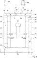
- the thick matter pump further comprises a connecting piece 58 which is provided to hydraulically connect the drive cylinders 23, 24 to one another (cf. Fig. 6 ).
- the connecting piece 58 is provided for configuring the control valve 48.
- the connecting piece 58 is constructed in several parts.
- the pressure volumes 27, 28 and / or the pressure volumes 29, 30 are connected to the hydraulic pump 40 and the operating medium sump 46 via the connecting piece 58.
- the connecting piece 58 has two operating medium connections 31 ', 35' to which the hydraulic lines 31, 35 are connected.
- the connecting piece 58 is supplied with operating fluid via the operating fluid connection 31 '.
- the operating medium is fed back into the operating medium sump 46 via the operating medium connection 35 ′.
- the hydraulic lines 32, 33 between the Control valve 48 and the pressure volume 27, 28 are arranged, are integrated in the connecting piece 58. In particular, they are not designed as flexible lines.
- the connecting piece 58 has two operating medium connections 49 ′, 50 ′, which are provided for connecting the control valves 49, 50.
- the control valves 49, 50 can alternatively also be integrated into the connecting piece 58.
- the connecting piece 58 is provided in particular to change an operating medium pressure and / or an operating medium quantity in at least one of the pressure volumes 27, 28, 29, 30.
- a configuration of the connecting piece 58 is basically independent of a subdivision of the conveying cycle 14 into subsections 18.
- the connecting piece 58 in which the connecting piece 58 is provided for controlling the operating medium pressure and / or the amount of operating medium in all pressure volumes 27, 28, 29, 30, the connecting piece 58 comprises a plurality of valve recesses 61 Built-in valves 59 or for receiving slide shafts 60 are provided.
- the connecting piece 58 comprises a plurality of slide shafts 60 which are arranged axially displaceably within the valve recesses 61.
- the connecting piece 58 can have a plurality of built-in valves 59 which are inserted into the valve recesses 61.
- the slide shafts 60 are provided to connect the operating medium connections 31 ', 35', 49 ', 50' to one another in different ways.
- the slide shafts 60 and / or the built-in valves 59 in particular the operating medium pressure and / or the amount of operating medium in the pressure volumes 27, 28, 29, 30 can be changed.
- the slide shafts 60 can be controlled hydraulically and / or electrically. Solenoid valves are particularly advantageous as built-in valves 59. In principle, however, other valves can also be used.
- the adjusting unit includes a further control valve 51.
- the control valve 51 is arranged between the hydraulic line 31, which is designed as a supply line, and the two hydraulic lines 36, 37 to which the plunger cylinders of the adjusting cylinder unit 47 are connected.
- the control valve 51 is also designed as a 4/3-way valve. It is connected in parallel with the control valve 48.
- the control valve 51 also includes two actuators for control.
- one of the control valves 48, 51 can also be hydraulically operated and connected to the other control valve 48, 51, so that the actuators of the corresponding control valve 48, 51 can be dispensed with.
- the pump device in the illustrated embodiment comprises two position sensors 62, 63, which are provided to provide a signal when the transfer tube 44 is completely switched.
- the pump device can also have a displacement sensor which is provided to detect a current position of the plunger cylinder.
- the control and regulating unit 17 is provided to use the position sensors 62, 63 to detect a complete switchover of the transfer tube 44 into its switching positions.
- any desired sensors can be used to detect the switchover of the diverter valve 44, such as magnetic field sensors or electrical resistance sensors.
- the control valve 48 is switched to the first switching position.
- the control valve 51 for controlling the diverter valve 44 is switched to the second switching position in this conveying cycle 14.
- the first pressure volume 27 of the first drive cylinder 23, whose drive piston 25 is with that for the pumping stroke provided first delivery piston 12 is connected, acted upon by an operating medium pressure.
- the second pressure volume 29 of the first drive cylinder 23 decreases.
- the operating medium displaced from the second pressure volume 29 flows via the hydraulic line 34, which is designed as a swing line, into the second pressure volume 30 of the second drive cylinder 24, causing the second drive piston 26 to run in opposite directions is moved to the first drive piston 25.
- the second delivery piston 13 thereby executes the suction stroke.
- the first pressure volume 28 of the second drive cylinder 24 is depressurized.
- the control valve 48 When the delivery cycle 14 has ended, i.e. the delivery pistons 12, 13 have reached their dead centers, the control valve 48 is switched to the middle switching position to control the drive cylinders 23, 24. The control valve 51 is then switched to the first switching position to control the transfer tube 44. As soon as the transfer tube 44 is switched over, the control valve 48 for controlling the drive cylinders 23, 24 is switched to the second switching position, whereby in the next delivery cycle 14 the first delivery piston 12 performs a suction stroke and the second delivery piston 13 performs a pumping stroke.
- the operating medium pressure that prevails in the pressure volumes 27, 28, 29, 30 of the drive cylinders 23, 24 corresponds to the feed pressure 16 of the corresponding delivery piston 12, 13 during a delivery cycle 14.
- the feed speed 15, which the corresponding delivery piston 12, 13 has during the delivery cycle 14 depends on properties of the concrete, such as, in particular, a flow rate that the concrete has and the maximum feed pressure 16 that the hydraulic pump 40 provides.
- the feed rate 15 is thus limited by the maximum operating medium pressure that can be provided by the hydraulic pump 40.
- the feed rate 15 can thus be set in particular by changing the amount of operating medium provided by the hydraulic pump 40 and / or by changing the maximum pressure provided by the hydraulic pump 40. Using the setting unit and of the control and regulating unit 17, the feed pressure 16 and the feed speed 15 of the delivery pistons 12, 13 can thus be changed.
- the control and regulating unit 17 is provided to subdivide the conveying cycle 14 into several subsections 18.
- the feed speed 15 and the feed pressure 16 can be specified individually for each of the subsections 18.
- the subsections 18 into which the control and regulating unit 17 subdivides each conveying cycle 14 are designed as path sections in the exemplary embodiment shown.
- the delivery pistons 12, 13 can be moved over a maximum distance that is defined by the two dead points of the corresponding delivery piston 12, 13.
- the control and regulating unit 17 divides this path of each delivery piston 12, 13 into equally large path sections.
- the path sections then form the subsections 18 for which the feed speed 15 and the feed pressure 16 of the corresponding delivery piston 12, 13 can each be individually adjusted.
- the diverter valve 44 is provided to be switched over into the two subsections 18 independently of a subdivision of the at least one conveying cycle 14.
- the subsections 18 are thus independent of a current switching state of the transfer tube 44.
- the transfer tube 44 is provided to be switched between two conveying cycles, ie the transfer tube 44 is switched between the switching positions while the delivery pistons 12, 13 are in the dead centers. Movement of the delivery pistons 12, 13 is prevented while the transfer tube 44 is switched over. A switchover of the diverter valve 44 is separated in time from the conveyor cycles 14.
- the diverter valve 44 is switched to one of the switching positions, ie it is in an end position and is not switched to an intermediate state between the switching positions.
- the subsections 18 thus only subdivide the conveying cycle 14 independently of the switchover of the transfer tube 44.
- the control and regulating unit 17 is accordingly provided to subdivide the conveying cycle 14 into the at least two subsections 18 after the diverter valve 44 has been switched to one of its switching positions.
- the control and regulating unit 17 is provided to use the position sensors 62, 63 to detect the complete switchover of the transfer tube 44 into one of its switching positions.
- the switchover of the diverter valve 44 can at least partially overlap in time with at least one of the conveying cycles 14.
- the control and regulating unit 17 is provided to apply a pressure to at least one of the pressure volumes 27, 28, 29, 30, which are limited by the drive cylinders 23, 24 for the delivery pistons 12, 13, in order to achieve the to adjust the corresponding delivery piston 12, 13, while at the same time the adjusting cylinder unit 47 of the transfer tube 44 is pressurized.
- control and regulating unit 17 is provided in at least one operating mode in addition to the two sub-sections 18 into which the control and regulating unit 17 divides the conveying cycle 14, at least one further sub-section for adjusting the transfer tube 44 is provided.
- the subsections 18 are independent of a current switching state of the diverter valve 44.
- the other subsections provided for adjusting the diverter valve 44 depend on the current switching state of the diverter valve 44.
- further subsections 18 can also be provided for switching over the diverter valve 44. For the switchover of the diverter valve 44, in particular the first section 18 and the last section 18 of a conveying cycle 14 can be provided.
- the further subdivision of the conveying cycle 14 into the at least two subsections 18 is fundamentally independent of the subsections which are provided for switching over the transfer tube 44.
- the subsections that are provided for switching the diverter valve 44 can be setpoint specifications for a switching pressure and / or a switching speed of the adjusting cylinder unit 47 can be provided.
- the thick matter pump also has an operating unit 19 for entering parameters on which the feed speed 15 and the feed pressure 16 at least depend.
- the operating unit 19 comprises vehicle-mounted operating elements and a remote control.
- the parameters that can be entered by means of the operating unit 19 are designed as setpoint specifications for the corresponding subsection 18 and are provided for setting the feed speed 15 and the feed pressure 16 by the control and regulating unit 17.
- At least one parameter can be entered for each subsection 18.
- For each sub-section 18 of the conveying cycle 14, at least one setpoint specification can be entered, on which the feed rate 15 and the feed pressure 16 in the corresponding sub-section 18 at least depend.
- the control and regulating unit 17 adjusts in particular the speed of the drive machine 41 and the angle of inclination of the swash plate 42 of the hydraulic pump 40 in order to set at least the feed rate 15 in accordance with the setpoint specifications.
- the parameters that can be entered by means of the operating unit 19 are designed as values for the feed rate 15.
- the operating unit 19 has a first switch 52, by means of which a number of the subsections 18 into which the control and regulating unit 17 subdivides the conveying cycle 14 can be set.
- the operating unit 19 also has a switch 53, by means of which the feed rate 15 can be specified as a parameter for each subsection 18.
- the operating unit 19 also has an additional switch 54, by means of which the setpoint specification, the feed pressure 16, can be set as a parameter for each subsection 18.
- the switch 54 can be embodied, for example, by means of a touchscreen. In principle, however, a different assignment of the switches 52, 53, 54 shown is also conceivable. In particular, it is conceivable that the switches 53, 54 are each used to set Setpoint specifications are provided as parameters for part of the subsections 18.
- the switches 52, 53, 54 are preferably provided on the remote control.
- one switch 53 can be provided for setting a setpoint specification for the feed rate 15 in the first subsections 18 and the other switch 54 for setting a setpoint specification for the feed rate 15 in a further subsection 18.
- the control and regulating unit 17 is provided to independently calculate target value specifications for the remaining subsections 18 for which the operator has not entered a target value specification.
- the control and regulating unit 17 then interpolates the setpoint assignments for the remaining subsections 18, for example by making them for the first to fifth subsections 18 sets a steadily increasing amount of operating resources and for the fifth to last subsection 18 a steadily decreasing amount of operating resources as setpoint specifications.
- Both the individual target value specifications for interpolation of all target value specifications and the directly input target value specifications for all subsections 18 can optionally be set variably or fixed values are specified.
- the thick matter pump has a sensor unit.
- the sensor unit is provided for determining the feed speed 15 and for determining the feed pressure 16.
- the sensor unit comprises a pressure sensor 20, a displacement sensor 21 and a position sensor 22.
- the sensor unit can additionally be provided for monitoring the feed speed 15 and / or the feed pressure 16.
- the sensor unit further comprises a speed sensor 57 for determining the speed of the drive machine 41.
- the pressure sensor 20 is provided to determine the feed pressure 16.
- the pressure sensor 20 detects the operating medium pressure in the hydraulic lines 32, 33.
- the operating medium pressure is in turn directly proportional to the feed pressure 16.
- the control and regulating unit 17 can determine the feed pressure 16 directly by means of the pressure sensor 20.
- the displacement sensor 21 for determining the feed speed 15 of the delivery piston 12 can have different configurations.
- the travel sensor 21 can be designed as a cable sensor in which a change in travel distance is transmitted via a cable to a sensor wheel, the rotational movement of which is detected by a corresponding rotary encoder.
- other configurations are also conceivable, for example with electrical sensors that determine the distance based on an electrical resistance, or optical transmitters.
- the position sensor 22 is provided for determining a position of the delivery piston 13. Due to the movement-related coupling of the two delivery pistons 12, 13 via the hydraulic line 34, the position of the delivery piston 13 basically corresponds to the opposite position of the delivery piston 12.
- the position sensor 22 is used in particular to compare the positions of the delivery pistons 12, 13.
- the position sensor 22 can also be used for a control of other components can be used.
- the position sensor 22 and / or an equivalently arranged position sensor provided for determining a position of the feed piston 14 can be provided to subdivide the feed cycle 14 into the subsections 18, which in this case are designed as path sections and in which the feed rate 15 and / or the feed pressure 16 can be set individually.
- the setting unit is provided to set different feed speeds 15 and different for the two delivery pistons 12, 13 Set feed pressures 16.
- the conveying piston 12, 13, which executes a pumping stroke at least temporarily has a different feed rate 15 and a different advance pressure 16 than the conveying piston 12, 13, which executes a suction stroke.
- the sensor unit is provided to determine, in particular, the feed speeds 15 of the two delivery pistons 12, 13 separately from one another.
- the setting unit has the two further control valves 49, 50 (cf. Figure 5 ).
- the control valve 49 is arranged between the hydraulic line 32 for supplying the first drive cylinder 23 and the hydraulic line 34 designed as a swing line.
- the second control valve 50 is arranged between the hydraulic line 33 for supplying the second drive cylinder 24 and the hydraulic line 34 designed as a swing line.
- the further control valves 49, 50 are provided to change a quantity of operating medium in the second pressure volumes 29, 30 of the drive cylinders 23, 24 and the hydraulic line 34, which connects the pressure volumes 29, 30.
- the control valves 49, 50 are designed as proportional valves.
- the hydraulic line 32, 33 of the drive cylinder 23, 24, which executes a pump stroke has a significantly higher operating medium pressure than the hydraulic line 32, 33 of the drive cylinder 23, 24, which executes a suction stroke.
- the operating medium pressure in the hydraulic line 34 which is designed as a swing line, is significantly lower than the operating medium pressure in the hydraulic line 32, 33 of the drive cylinder 23, 24, which executes a pumping stroke.
- the operating medium pressure in the hydraulic line 34 is equal to the feed pressure 16, which is necessary for sucking concrete from the material feed container 38, while the operating medium pressure in the hydraulic line 32, 33 of the drive cylinder 23, 24, which performs a pumping stroke, corresponds to the feed pressure 16, which this is necessary in order to press the concrete into the delivery line 39.
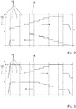
- the setting unit is provided to specify different feed speeds 15 and different feed pressures 16 for the feed pistons 12, 13, the setpoint specifications for the feed speed 15 of the feed piston 12, 13, which carries out the pumping stroke, and the setpoint specifications for the feed speed 15 of the feed piston 12 can be set , 13, which performs the suction stroke, have different values in the individual subsections 18 (cf. Figure 2 ). If the setpoint specifications for the feed speed 15 of the feed piston 12, 13, which executes the pumping stroke, and the setpoint specifications for the feed speed 15 of the feed piston 12, 13, which performs the suction stroke, are the same, the control valves 48, 49 can remain closed (cf. Figure 3 ).
- the sensor unit has two flow sensors 55, 56 which are provided to determine changes in the amount of operating medium in the pressure volumes 29, 30 and the hydraulic line 34.
- the flow sensors 55, 56 are each connected in series with one of the control valves 49, 50.
- the control and regulating unit 17 can determine the feed speed 15 of the second feed piston 13 on the basis of the feed speed 15 of the first feed piston 12.
- the position sensor 22 is used in particular to verify the feed rate 15 determined in this way.
- the control and regulation unit 17 is provided in particular to increase the feed speeds 15 by changing the feed pressure 16 To regulate setpoint specifications.
- the control and regulating unit 17 can additionally or alternatively be provided to regulate the feed pressure 16 to preset target values.
- the control and regulating unit 17 is provided to change the speed of the drive machine 41 and the angle of inclination of the swash plate 42 of the hydraulic pump 40 in addition to controlling the control valves 48, 49, 50.
- control and regulating unit 17 divides the conveying cycle 14 into the subsections 18, an operator uses the switch 52 to specify a number of the subsections 18 as a setpoint specification.
- the operator uses the switch 53 to define parameters for the feed speeds 15 as target value specifications.
- the control and regulating unit 17 then switches on the hydraulic pump 40 and increases the speed of the drive machine 41 to a value resulting from the setpoint specifications.
- the feed speed 15 is controlled as a function of the feed pressure 16.
- the delivery pistons 12, 13 are subjected to the highest possible feed pressure 16, which is possible by controlling the hydraulic pump 40 and the drive machine 41.
- the maximum acceleration the concrete is compressed in the delivery cylinder 10, 11, which performs a pump stroke.
- a value at which optimum compression is given is stored as setpoint specifications for the feed pressure 16 as a function of which the feed speed 15 is controlled. If the setpoint specification for the feed pressure 16 at the pressure sensor 20 is reached and the concrete is thus sufficiently compressed, the acceleration of the delivery pistons 12, 13 is stopped.
- the delivery pistons 12, 13 continue to travel at a constant feed speed 15, for example.
- the concrete is pushed out of the corresponding delivery cylinder 10, 11.
- the delivery pistons 13 are preferably moved in each of the subsections 18 at a constant feed rate 15 until the next subsection 18 is reached.
- the next subsection 18 can have other setpoint values for the feed speed 15 and / or the feed pressure 16.
- the feed rate 15 is accelerated or decelerated again until the corresponding setpoint specification is reached.
- the feed speed 15 of the delivery pistons 12, 13 is reduced to zero.
- the diverter valve 44 is switched over and the next conveying cycle 14 can begin.
- control and regulating unit 17 has a memory which is provided for storing sequence programs.
- the sequence programs can be predefined, i.e. the sequence programs are stored in the memory by the manufacturer.
- an operator can store his own sequence programs or that the operator can change the predefined sequence programs.
- the sequence programs correspond to a set of freely definable setpoint specifications. The operator can select and / or change the different sequence programs using switches 52, 53, 54.
- the control and regulation unit 17 independently determines setpoint specifications for the feed rate 15 and / or the feed pressure 16.
- the control and regulating unit 17 provides setpoint specifications for the feed speed 15 and / or the feed pressure 16, which are a Operator can take over or change.
- the operating unit 19 can be provided for entering a concrete code as a parameter, on the basis of which the control and regulating unit 17 determines the setpoint values.
- the concrete code is preferably made available by a supplier, such as a concrete plant or a mixing plant, of the concrete to be pumped, for example in the form of an online transmission, in the form of a barcode or in the form of an RFID tag.
- a supplier such as a concrete plant or a mixing plant
- the concrete code defines essential properties of the concrete to be pumped. For this operating mode, setpoint values are stored in the control and regulation unit 17, which are selected and activated when the corresponding concrete code is entered.
- the sensor unit can, for example, have a sensor which is provided to determine essential properties of the concrete, such as in particular its flow rate.
- a characteristic curve is stored in the control and regulation unit 17 for such an operating mode, which, depending on the properties of the concrete for the individual subsections 18 of the conveying cycle 14, determines setpoint values for the feed speed 15 and the feed pressure 16.
- the control and regulating unit 17 can have different characteristics for the delivery piston 12, 13, which performs the pumping stroke, and the delivery piston 12, 13, which performs the suction stroke.
- the control and regulating unit 17 can also have an operating program in which secondary parameters are used to determine the target value specifications. Secondary parameters are, in particular, parameters that are not determined directly in the thick matter pump.
- the sensor unit has sensors which are provided, for example, to determine a movement of the boom or to determine support forces.
- the control and regulating unit 17 recognizes a Vibration of the boom, which can be traced back to the thick matter pump, changes the control and regulation unit 17 the setpoint specifications for the individual subsections 18 of the conveying cycle 14 Sub-sections 18 of the conveyor cycle 14 until the vibrations are minimized.
- control and regulating unit 17 In particular in the operating modes in which the control and regulating unit 17 independently changes the feed speed 15 and the feed pressure 16 in the individual subsections 18, the control and regulating unit 17 is provided to determine a degree of filling of the feed cylinders 10, 11.
- the control and regulation unit 17 calculates an expected degree of filling and changes the feed speed 15 and the feed pressure 16 until the filling wheel is at its maximum.
- the control and regulating unit 17 determines the degree of filling, the control and regulating unit 17 is provided to maximize the degree of filling.
- control and regulation unit 17 is provided to provide a setpoint value for the feed speed 15 and / or the feed pressure 16, which is defined when the conveyor cycle 14 is divided into the subsections 18, with an actual value for the feed speed 15 and / or to compare the feed pressure 16 which was actually reached during the corresponding subsection 18. If the control and regulating unit 17 detects a discrepancy between the actual value and the target value, the control and regulating unit 17 is provided in the corresponding operating mode to generate the target value for the corresponding subsection in a subsequent conveying cycle 14 and / or in a subsequent subsection 18 18 adapt. In addition, the control and regulating unit 18 is provided to compare actual values of successive subsections 18 in relation to the associated setpoint values.
- the control and regulating unit 17 is then provided to set the setpoint for the feed speed 15 and / or the feed pressure 16 in the subsequent conveying cycle 14 change.
- the control and regulation unit 17 can also be provided to change the subdivision into the subsections 18, ie in particular a number or length of the subsections 18, in the event of a discrepancy between the nominal value and the actual value in the subsequent conveying cycle 14.
Landscapes
- Engineering & Computer Science (AREA)
- Mechanical Engineering (AREA)
- General Engineering & Computer Science (AREA)
- Reciprocating Pumps (AREA)
Claims (23)
- Pompe à substances épaisses, comprenant deux cylindres de refoulement (10, 11), deux pistons de refoulement (12, 13) et, pour entraîner les pistons de refoulement (12, 13), un entraînement hydraulique pourvu d'une pompe hydraulique (40), deux vérins d'entraînement (23, 24) et deux pistons d'entraînement (25, 26), les pistons de refoulement (12,13) étant guidés dans les cylindres de refoulement (10, 11) respectivement associés et étant prévus pour être déplacés dans une impulsion aller (14), d'un premier point mort dans un deuxième point mort, et dotée d'une unité de réglage et d'une unité de commande et/ou de régulation (17), qui sont prévues pour modifier au moins une vitesse d'avance (15) et/ou une pression d'avance (16) de l'au moins un piston de refoulement (12, 13) pendant l'impulsion aller (14),l'unité de commande et/ou de régulation (17) étant prévue pour diviser l'impulsion aller (14) en au moins deux sections partielles (18) pour lesquelles la vitesse d'avance (15) et/ou la pression d'avance (16) sont individuellement réglables,la pompe à substances épaisses comportant une unité opérationnelle (19), destinée à saisir au moins un paramètre pour au moins une section partielle (18), duquel la vitesse d'avance (15) et/ou la pression d'avance (16) dépend au moins dans l'au moins une section partielle (18), etune pièce de liaison (58) qui relie hydrauliquement entre eux des vérins d'entraînement (23, 24),caractérisée en ce quela pièce de liaison (58) comprend une multiplicité d'évidements pour vannes (61), les évidements pour vannes (61) étant prévus pour recevoir de préférence des vannes intégrées (59) ou des arbres poussoirs (60).
- Pompe à substances épaisses selon la revendication 1, caractérisée en ce que les sections partielles (18), qui sont prévues pour l'impulsion aller sont conçues sous la forme de sections de course et/ou de sections temporelles.
- Pompe à substances épaisses selon la revendication 1 ou 2,
caractérisée en ce que les pistons d'entraînement (25, 26) sont conçus à double action, suite à quoi, ils enferment avec les vérins d'entraînement (23, 24) chaque fois deux volumes de pression (27, 28, 29, 30) par lesquels les pistons d'entraînement (25, 26) peuvent être déplacés dans les deux directions, les volumes de pression (27, 28) et/ou les volumes de pression (29, 30) étant reliés par l'intermédiaire de la pièce de liaison (58) avec la pompe hydraulique (40) et une cuve basse de matière consommable (46). - Pompe à substances épaisses selon au moins l'une quelconque des revendications 1 à 3,
caractérisée en ce quedans la pièce de liaison (58) sont intégrées des vannes de commande (49, 50), la pièce de liaison (58) étant prévue pour modifier une pression de matière consommable et/ou une quantité de matière consommable dans au moins l'un des volumes de pression (27, 28, 29, 30), et/ouen ce que la pièce de liaison (58) est prévue pour constituer la vanne de commande (48), la pièce de liaison (58) étant réalisée de préférence en plusieurs parties. - Pompe à substances épaisses selon au moins l'une quelconque des revendications 1 à 4,
caractérisée en ce que la pièce de liaison (58) comporte deux raccords de matière consommable (31', 35') sur lesquels sont reliées des conduites hydrauliques (31, 35), la pièce de liaison (58) étant alimentée avec de la matière consommable par l'intermédiaire du raccord de matière consommable (31'), de la matière consommable étant ramenée par l'intermédiaire du raccord de matière consommable (35') dans la cuve basse de matière consommable (46), le cas échéant, des conduites hydrauliques (32, 33) étant placées entre une vanne de commande (48) et les volumes de pression (27, 28) et étant intégrées dans la pièce de liaison (58), les conduites hydrauliques (32, 33) de la pièce de liaison (58) étant réalisées de préférence sous la forme de conduites non flexibles. - Pompe à substances épaisses selon au moins l'une quelconque des revendications 1 à 5,
caractérisée en ce que la vanne de commande (48) est conçue pour actionner les vérins d'entraînement (23, 24) ou sous la forme d'une vanne à 4/3 voies. - Pompe à substances épaisses selon au moins l'une quelconque des revendications 1 à 6,
caractérisée en ce que pour la liaison des vérins d'entraînement (23, 24) avec la pompe hydraulique (40), la pompe à substances épaisses comprend un système hydraulique, doté d'une multiplicité de conduites hydrauliques (31, 32, 33, 34, 35), la conduite hydraulique (34) créant une conduite à bascule, qui est prévue pour un accouplement par mouvement des pistons de refoulement (12, 13), le système hydraulique étant réalisé sous la forme d'un système hydraulique ouvert et/ou au moins partiellement, sous la forme d'un système hydraulique fermé. - Pompe à substances épaisses selon au moins l'une quelconque des revendications 1 à 7,
caractérisée en ce que les deux vérins d'entraînement (23, 24) et les deux pistons d'entraînement (25, 26) accouplés avec chacun de l'un des pistons de refoulement (12, 13) qui sont guidés dans les vérins d'entraînement (23, 24) et qui avec les vérins d'entraînement (23, 24) délimitent chacun au moins un volume de pression (29, 30), ainsi que la conduite hydraulique (34), qui relie l'un à l'autre les volumes de pression (29, 30), l'unité de réglage étant prévue pour modifier une quantité de matière de production dans les volumes de pression (29, 30) et dans la conduite hydraulique (34). - Pompe à substances épaisses selon au moins l'une quelconque des revendications 1 à 8,
caractérisée en ce que la pompe à substances épaisses comporte une unité de capteurs, destinée à déterminer directement ou indirectement la vitesse d'avance (15) et/ou la pression d'avance (16), de préférence, l'unité de capteurs comprenant- un capteur de pression (20), destiné à déterminer la pression d'avance (16), au moyen du capteur de pression (20), l'unité de commande et/ou de régulation (17) étant apte à déterminer directement la pression d'avance (16),- un capteur de course (21), destiné à déterminer la vitesse d'avance (15) du piston de refoulement (12),- un capteur de position (22), destiné à déterminer une position du piston de refoulement (12, 13), ainsi que- le cas échéant, un capteur de régime (57), destiné à déterminer le régime de la machine d'entraînement (41). - Pompe à substances épaisses selon au moins l'une quelconque des revendications 1 à 9, caractérisée en ce que la pompe à substances épaisses comprend un aiguillage tubulaire (44), l'aiguillage tubulaire (44) étant apte à être commuté dans les deux sections partielles 18, l'aiguillage tubulaire (44) se chevauchant au moins partiellement dans le temps avec l'au moins une impulsion aller (14), l'unité de commande et/ou de régulation (17) étant prévue pour soumettre à une pression au moins l'un des volumes de pression (27, 28, 29, 30), lesquels sont délimités par les vérins d'entraînement (23, 24) pour les pistons de refoulement (12, 13, pour déplacer le piston de refoulement (12, 13) correspondant, alors que simultanément, une unité de vérin de déplacement (47) de l'aiguillage tubulaire (44) est soumise à une pression.
- Pompe à substances épaisses selon au moins l'une quelconque des revendications 1 à 10, caractérisée en ce que la pompe à substances épaisses comprend au moins un capteur de position et/ou de course (21, 22), qui est prévu pour déterminer une position de l'au moins un piston de refoulement (12, 13), l'unité de commande et/ou de régulation (17) étant prévue pour diviser l'impulsion aller (14) dans les sections partielles (18), à l'aide d'un signal de position et/ou de course de l'au moins un capteur de position et/ou de course (21, 22).
- Pompe à substances épaisses selon au moins l'une quelconque des revendications 1 à 11, caractérisée en ce que les sections partielles (18), qui sont prévues pour le changement de l'aiguillage tubulaire (44) comportent des prescriptions de valeurs de consigne pour une pression de changement et/ou une vitesse de changement de l'unité de vérin de déplacement (47).
- Pompe à substances épaisses selon au moins l'une quelconque des revendications 9 à 12, caractérisée en ce que l'unité de capteurs est prévue pour déterminer séparément les vitesses d'avance (15) des au moins deux pistons de refoulement (12, 13).
- Pompe à substances épaisses selon au moins l'une quelconque des revendications 1 à 13, caractérisée en ce que l'unité de commande et/ou de régulation (17) comporte une mémoire, destinée à mémoriser au moins un programme d'exécution avec au moins une prescription de valeur de consigne.
- Pompe à substances épaisses selon la revendication 14, caractérisée en ce que- l'au moins un programme d'exécution est sauvegardé de manière prédéfinie et par le fabricant dans la mémoire,- l'opérateur peut sauvegarder de propres programmes d'exécution,- l'opérateur peut modifier les programmes d'exécution prédéfinis,
ou- l'opérateur sélectionne et/ou modifie les différents programmes d'exécution au moyen d'interrupteurs (52, 53, 54). - Pompe à substances épaisses selon au moins l'une quelconque des revendications 1 à 15, caractérisée en ce que la pompe à substances épaisses comporte une unité opérationnelle (19) avec interrupteurs (52, 53, 54), au moyen- d'interrupteurs (52), un nombre des sections partielles (18), dans lequel l'unité de commande et/ou de régulation (17) divise l'impulsion aller (14) étant réglable,- d'interrupteurs (53), pour chaque section partielle (18), la vitesse d'avance (15) étant prédéfinissable en tant que paramètre, et/ou- d'interrupteurs (54), pour chaque section partielle (18), la prescription de valeur de consigne de la pression d'avance (16) pouvant être réglée en tant que paramètre.
- Pompe à substances épaisses selon au moins l'une quelconque des revendications 1 à 16, caractérisée en ce que l'unité opérationnelle (19) est prévue pour la saisie variable d'une valeur pour l'au moins un paramètre et/ou pour la sélection dans une liste prévue de valeurs pour l'au moins un paramètre, de préférence, l'opérateur pouvant régler pour la vitesse d'avance (15) et/ou la pression d'avance (16) des valeurs quelconques ou quasiment quelconques comprises entre 0 % et 100 %.
- Pompe à substances épaisses selon au moins l'une quelconque des revendications 1 à 17, caractérisée en ce que l'au moins un paramètre est conçu sous la forme d'une prescription de valeur de consigne pour le réglage de la vitesse d'avance (15) et/ou de la pression d'avance (16).
- Pompe à substances épaisses selon au moins l'une quelconque des revendications 1 à 18, caractérisée en ce que l'unité de réglage- comporte une vanne de commande (51) pour l'actionnement de l'unité de vérin de déplacement (47), et/ou- est prévue pour régler dans au moins une section partielle (18) pour les pistons de refoulement (12, 13) différentes vitesses d'avance (15) et/ou différentes pressions d'avance (16).
- Dispositif de pompage de béton, pourvu d'une pompe à substances épaisses selon l'une quelconque des revendications précédentes.
- Dispositif de pompage de béton selon la revendication 20, caractérisé en ce que pour détecter une position de commutation de l'unité de vérin de déplacement (47), le dispositif de pompage comprend des capteurs de position (62, 63) et/ou un capteur de course, pour détecter une position actuelle du vérin à piston plongeur.
- Procédé opérationnel d'une pompe à substances épaisses selon l'une quelconque des revendications 1 à 19, lors duquel au moins un piston de refoulement (12, 13) guidé dans au moins un cylindre de refoulement (10, 11) est déplacé dans une impulsion aller (14), d'un premier point mort dans un deuxième point mort, et lors duquel, une vitesse d'avance (15) et/ou une pression d'avance (16) de l'au moins un piston de refoulement (12, 13) est modifiée pendant l'impulsion aller (14), l'impulsion aller (14) étant divisée en au moins deux différentes sections partielles (18), pour lesquelles la vitesse d'avance (15) et/ou la pression d'avance (16) sont réglées individuellement, caractérisé en ce quesur l'unité opérationnelle (19) de la pompe à substances épaisses, au moins un paramètre, dont dépend au moins la vitesse d'avance (15) et/ou la pression d'avance (16) dans l'au moins une section partielle (18) est saisi pour au moins une section partielle (18), eten ce qu'une pièce de liaison (58) relie l'un à l'autre de manière hydraulique les vérins d'entraînement (23, 24), la pièce de liaison (58) comprenant une multiplicité d'évidements pour vannes (61), les évidements pour vannes (61) étant prévus de préférence pour recevoir des vannes intégrées (59) ou des arbres poussoirs (60).
- Procédé selon la revendication 22, caractérisé en ce que- dans une première section partielle (18), la vitesse d'avance (15) est commandée en fonction de la pression d'avance (16), une section partielle (18) suivante comportant d'autres prescriptions de valeurs de consigne,- dans la section partielle (18) suivante, la vitesse d'avance (15) et/ou la pression d'avance (16) est accélérée ou temporisée jusqu'à ce que la prescription de valeur de consigne correspondante soit atteinte, et/ou- dans la dernière section partielle (18), la vitesse d'avance (15) est réduite à zéro.
Applications Claiming Priority (1)
| Application Number | Priority Date | Filing Date | Title |
|---|---|---|---|
| DE102013104494.8A DE102013104494B4 (de) | 2013-05-02 | 2013-05-02 | Dickstoffpumpe |
Publications (3)
| Publication Number | Publication Date |
|---|---|
| EP2799712A2 EP2799712A2 (fr) | 2014-11-05 |
| EP2799712A3 EP2799712A3 (fr) | 2014-11-12 |
| EP2799712B1 true EP2799712B1 (fr) | 2021-10-06 |
Family
ID=50396890
Family Applications (1)
| Application Number | Title | Priority Date | Filing Date |
|---|---|---|---|
| EP14161785.2A Not-in-force EP2799712B1 (fr) | 2013-05-02 | 2014-03-26 | Pompe à liquides épais |
Country Status (2)
| Country | Link |
|---|---|
| EP (1) | EP2799712B1 (fr) |
| DE (1) | DE102013104494B4 (fr) |
Families Citing this family (10)
| Publication number | Priority date | Publication date | Assignee | Title |
|---|---|---|---|---|
| DE102013104494B4 (de) | 2013-05-02 | 2023-11-30 | MPS-Matter Pumpsysteme GmbH | Dickstoffpumpe |
| US11149725B2 (en) | 2016-01-20 | 2021-10-19 | Weir Minerals Netherlands B.V. | Hydraulic pump system for handling a slurry medium |
| KR101994392B1 (ko) * | 2018-03-21 | 2019-06-28 | 가천대학교 산학협력단 | 콘크리트 펌프차량의 콘크리트 펌핑 시스템 및 방법 |
| DE102018208263A1 (de) * | 2018-05-25 | 2019-11-28 | Putzmeister Engineering Gmbh | Vorrichtung zur Förderung von Dickstoff |
| DE102019214034A1 (de) | 2019-09-13 | 2021-03-18 | Putzmeister Engineering Gmbh | Verfahren zum Betreiben einer Arbeitsmaschine und Arbeitsmaschine |
| CN111852806A (zh) * | 2020-06-17 | 2020-10-30 | 中国中元国际工程有限公司 | 一种跑道融雪复合管用注浆泵及其工作方法 |
| DE102020207970A1 (de) * | 2020-06-26 | 2021-12-30 | Putzmeister Engineering Gmbh | Verfahren zum Betreiben einer Bau- und/oder Dickstoffpumpe zum Fördern von Bau- und/oder Dickstoff und Bau- und/oder Dickstoffpumpe zum Fördern von Bau- und/oder Dickstoff |
| DE102021202325A1 (de) | 2021-03-10 | 2022-09-15 | Putzmeister Engineering Gmbh | Verfahren zum Betreiben einer Bau- und/oder Dickstoffpumpe zum Fördern von Bau- und/oder Dickstoff und Bau- und/oder Dickstoffpumpe zum Fördern von Bau- und/oder Dickstoff |
| DE102021107139A1 (de) * | 2021-03-23 | 2022-09-29 | Putzmeister Engineering Gmbh | Betriebsüberwachung für ein Dickstofffördersystem |
| DE102024103029A1 (de) * | 2024-02-02 | 2025-08-07 | Putzmeister Engineering Gmbh | Verfahren zum Betreiben eines Bau- und/oder Dickstoffpumpensystems und Bau- und/oder Dickstoffpumpensystem |
Family Cites Families (10)
| Publication number | Priority date | Publication date | Assignee | Title |
|---|---|---|---|---|
| DE19503986A1 (de) * | 1995-02-07 | 1996-08-08 | Hudelmaier Ulrike | Verfahren und Vorrichtung zum Fördern von Beton oder anderen Dickstoffen |
| ITMI981571A1 (it) * | 1998-07-09 | 2000-01-09 | Cifa Spa | Pompa per cacestruzzo con mezzi di modulazione della velocita'dei pistoni dei cilindri del gruppo pompante |
| US6779983B1 (en) * | 2001-10-05 | 2004-08-24 | David A. Olson | Sludge pump with management system |
| DE10150467A1 (de) | 2001-10-16 | 2003-04-17 | Putzmeister Ag | Dickstoffpumpe mit Fördermengenregelung |
| JP4129761B2 (ja) | 2002-01-25 | 2008-08-06 | 石川島建機株式会社 | 往復動型粘性流体ポンプの運転制御装置 |
| DE10343802B4 (de) * | 2003-09-22 | 2007-12-06 | Schwing Gmbh | Kolben-Dickstoffpumpe mit kontinuierlichem Förderstrom |
| DE102004009362B4 (de) | 2004-02-26 | 2008-01-24 | Schwing Gmbh | Kolben-Dickstoffpumpe |
| DE102004015416A1 (de) | 2004-03-26 | 2005-10-13 | Putzmeister Ag | Vorrichtung und Verfahren zur Steuerung einer Dickstoffpumpe |
| FR2965313B1 (fr) | 2010-09-29 | 2012-09-07 | Exel Ind | Procede, dispositif et moyen d'entrainement de pompe a double effet a mouvement lineaire alternatif |
| DE102013104494B4 (de) | 2013-05-02 | 2023-11-30 | MPS-Matter Pumpsysteme GmbH | Dickstoffpumpe |
-
2013
- 2013-05-02 DE DE102013104494.8A patent/DE102013104494B4/de not_active Expired - Fee Related
-
2014
- 2014-03-26 EP EP14161785.2A patent/EP2799712B1/fr not_active Not-in-force
Non-Patent Citations (1)
| Title |
|---|
| None * |
Also Published As
| Publication number | Publication date |
|---|---|
| EP2799712A2 (fr) | 2014-11-05 |
| EP2799712A3 (fr) | 2014-11-12 |
| DE102013104494A1 (de) | 2014-11-06 |
| DE102013104494B4 (de) | 2023-11-30 |
Similar Documents
| Publication | Publication Date | Title |
|---|---|---|
| EP2799712B1 (fr) | Pompe à liquides épais | |
| DE69431276T2 (de) | Hydraulischer antrieb für hydraulische arbeitsmaschine | |
| DE112009003826B4 (de) | Hydrauliksteuerungssystem mit Strömungskraftkompensation | |
| EP2181221B1 (fr) | Mécanisme rotatif d'une excavatrice avec un entraînement hydraulique. | |
| EP1727980B1 (fr) | Dispositif et procede de commande d une pompe a pates a deux cylindres | |
| EP2050961B1 (fr) | Système d'entraînement hydraulique | |
| DE10152244B4 (de) | Compounder-Spritzgießmaschine | |
| DE102012105323A1 (de) | Steuervorrichtung zur Steuerung einer Kolbenpumpeneinheit für die Flüssigkeitschromatographie, insbesondere die Hochleistungsflüssigkeitschromatographie | |
| DE102016123612A1 (de) | System mit kombinierbaren Getriebe- und Werkzeugkreisen | |
| EP3807534B1 (fr) | Système d'entraînement hydraulique pour une pompe à matériaux de construction et pompe à matériaux de construction | |
| DE102011012714B4 (de) | Spritzgießmaschine | |
| WO2005093253A1 (fr) | Dispositif et procede de commande d'une pompe a pates | |
| EP2377999A1 (fr) | Entraînement avant d'une finisseuse de route et procédé de commande de celui-ci | |
| EP2895743A1 (fr) | Dispositif permettant de commander l'entraînement d'une pompe pour matières épaisses pourvue de deux cylindres | |
| EP1286058B1 (fr) | Système hydraulique pour des machines à moulage par injection | |
| EP3988801B1 (fr) | Procédé de fonctionnement d'un entraînement hydraulique | |
| WO2015067584A1 (fr) | Pompe pour liquide épais et unité d'amenée | |
| EP4305304B1 (fr) | Procédé pour faire fonctionner une pompe à matériau de construction et/ou à matériau visqueux destinée au transport de matériaux de construction et/ou de matériaux visqueux, et pompe à matériau de construction et/ou à matériau visqueux destinée au transport de matériaux de construction et/ou de matériaux visqueux | |
| DE102017213118A1 (de) | Ventilblockanordnung und Verfahren für eine Ventilblockanordnung | |
| DE69935551T2 (de) | Veränderung der Kolbengeschwindigkeit in einer Betonpumpe | |
| WO2020157046A1 (fr) | Engin de travail mobile et procédé pour faire fonctionner cet engin | |
| AT504416A2 (de) | Verfahren und vorrichtung für ein einspritzen bei einer spritzgiessmaschine | |
| AT524891B1 (de) | Hydraulische Antriebsvorrichtung für eine Formgebungsmaschine | |
| EP2853752A1 (fr) | Système de régulation | |
| EP0229330B1 (fr) | Mécanisme pivotant entraîné par deux cylindres séparés à bielle-manivelle |
Legal Events
| Date | Code | Title | Description |
|---|---|---|---|
| PUAL | Search report despatched |
Free format text: ORIGINAL CODE: 0009013 |
|
| PUAI | Public reference made under article 153(3) epc to a published international application that has entered the european phase |
Free format text: ORIGINAL CODE: 0009012 |
|
| 17P | Request for examination filed |
Effective date: 20140326 |
|
| AK | Designated contracting states |
Kind code of ref document: A2 Designated state(s): AL AT BE BG CH CY CZ DE DK EE ES FI FR GB GR HR HU IE IS IT LI LT LU LV MC MK MT NL NO PL PT RO RS SE SI SK SM TR |
|
| AX | Request for extension of the european patent |
Extension state: BA ME |
|
| AK | Designated contracting states |
Kind code of ref document: A3 Designated state(s): AL AT BE BG CH CY CZ DE DK EE ES FI FR GB GR HR HU IE IS IT LI LT LU LV MC MK MT NL NO PL PT RO RS SE SI SK SM TR |
|
| AX | Request for extension of the european patent |
Extension state: BA ME |
|
| RIC1 | Information provided on ipc code assigned before grant |
Ipc: F04B 9/10 20060101AFI20141009BHEP Ipc: F04B 49/20 20060101ALI20141009BHEP Ipc: F04B 49/08 20060101ALI20141009BHEP Ipc: F04B 15/02 20060101ALI20141009BHEP |
|
| R17P | Request for examination filed (corrected) |
Effective date: 20150507 |
|
| RBV | Designated contracting states (corrected) |
Designated state(s): AL AT BE BG CH CY CZ DE DK EE ES FI FR GB GR HR HU IE IS IT LI LT LU LV MC MK MT NL NO PL PT RO RS SE SI SK SM TR |
|
| STAA | Information on the status of an ep patent application or granted ep patent |
Free format text: STATUS: EXAMINATION IS IN PROGRESS |
|
| 17Q | First examination report despatched |
Effective date: 20170518 |
|
| GRAP | Despatch of communication of intention to grant a patent |
Free format text: ORIGINAL CODE: EPIDOSNIGR1 |
|
| STAA | Information on the status of an ep patent application or granted ep patent |
Free format text: STATUS: GRANT OF PATENT IS INTENDED |
|
| INTG | Intention to grant announced |
Effective date: 20210112 |
|
| GRAJ | Information related to disapproval of communication of intention to grant by the applicant or resumption of examination proceedings by the epo deleted |
Free format text: ORIGINAL CODE: EPIDOSDIGR1 |
|
| STAA | Information on the status of an ep patent application or granted ep patent |
Free format text: STATUS: EXAMINATION IS IN PROGRESS |
|
| INTC | Intention to grant announced (deleted) | ||
| GRAP | Despatch of communication of intention to grant a patent |
Free format text: ORIGINAL CODE: EPIDOSNIGR1 |
|
| STAA | Information on the status of an ep patent application or granted ep patent |
Free format text: STATUS: GRANT OF PATENT IS INTENDED |
|
| INTG | Intention to grant announced |
Effective date: 20210429 |
|
| GRAS | Grant fee paid |
Free format text: ORIGINAL CODE: EPIDOSNIGR3 |
|
| GRAA | (expected) grant |
Free format text: ORIGINAL CODE: 0009210 |
|
| STAA | Information on the status of an ep patent application or granted ep patent |
Free format text: STATUS: THE PATENT HAS BEEN GRANTED |
|
| AK | Designated contracting states |
Kind code of ref document: B1 Designated state(s): AL AT BE BG CH CY CZ DE DK EE ES FI FR GB GR HR HU IE IS IT LI LT LU LV MC MK MT NL NO PL PT RO RS SE SI SK SM TR |
|
| REG | Reference to a national code |
Ref country code: GB Ref legal event code: FG4D Free format text: NOT ENGLISH |
|
| REG | Reference to a national code |
Ref country code: CH Ref legal event code: EP Ref country code: AT Ref legal event code: REF Ref document number: 1436460 Country of ref document: AT Kind code of ref document: T Effective date: 20211015 |
|
| REG | Reference to a national code |
Ref country code: DE Ref legal event code: R096 Ref document number: 502014015918 Country of ref document: DE |
|
| REG | Reference to a national code |
Ref country code: IE Ref legal event code: FG4D Free format text: LANGUAGE OF EP DOCUMENT: GERMAN |
|
| REG | Reference to a national code |
Ref country code: LT Ref legal event code: MG9D |
|
| REG | Reference to a national code |
Ref country code: NL Ref legal event code: MP Effective date: 20211006 |
|
| PG25 | Lapsed in a contracting state [announced via postgrant information from national office to epo] |
Ref country code: RS Free format text: LAPSE BECAUSE OF FAILURE TO SUBMIT A TRANSLATION OF THE DESCRIPTION OR TO PAY THE FEE WITHIN THE PRESCRIBED TIME-LIMIT Effective date: 20211006 Ref country code: LT Free format text: LAPSE BECAUSE OF FAILURE TO SUBMIT A TRANSLATION OF THE DESCRIPTION OR TO PAY THE FEE WITHIN THE PRESCRIBED TIME-LIMIT Effective date: 20211006 Ref country code: FI Free format text: LAPSE BECAUSE OF FAILURE TO SUBMIT A TRANSLATION OF THE DESCRIPTION OR TO PAY THE FEE WITHIN THE PRESCRIBED TIME-LIMIT Effective date: 20211006 Ref country code: BG Free format text: LAPSE BECAUSE OF FAILURE TO SUBMIT A TRANSLATION OF THE DESCRIPTION OR TO PAY THE FEE WITHIN THE PRESCRIBED TIME-LIMIT Effective date: 20220106 |
|
| PG25 | Lapsed in a contracting state [announced via postgrant information from national office to epo] |
Ref country code: IS Free format text: LAPSE BECAUSE OF FAILURE TO SUBMIT A TRANSLATION OF THE DESCRIPTION OR TO PAY THE FEE WITHIN THE PRESCRIBED TIME-LIMIT Effective date: 20220206 Ref country code: SE Free format text: LAPSE BECAUSE OF FAILURE TO SUBMIT A TRANSLATION OF THE DESCRIPTION OR TO PAY THE FEE WITHIN THE PRESCRIBED TIME-LIMIT Effective date: 20211006 Ref country code: PT Free format text: LAPSE BECAUSE OF FAILURE TO SUBMIT A TRANSLATION OF THE DESCRIPTION OR TO PAY THE FEE WITHIN THE PRESCRIBED TIME-LIMIT Effective date: 20220207 Ref country code: PL Free format text: LAPSE BECAUSE OF FAILURE TO SUBMIT A TRANSLATION OF THE DESCRIPTION OR TO PAY THE FEE WITHIN THE PRESCRIBED TIME-LIMIT Effective date: 20211006 Ref country code: NO Free format text: LAPSE BECAUSE OF FAILURE TO SUBMIT A TRANSLATION OF THE DESCRIPTION OR TO PAY THE FEE WITHIN THE PRESCRIBED TIME-LIMIT Effective date: 20220106 Ref country code: NL Free format text: LAPSE BECAUSE OF FAILURE TO SUBMIT A TRANSLATION OF THE DESCRIPTION OR TO PAY THE FEE WITHIN THE PRESCRIBED TIME-LIMIT Effective date: 20211006 Ref country code: LV Free format text: LAPSE BECAUSE OF FAILURE TO SUBMIT A TRANSLATION OF THE DESCRIPTION OR TO PAY THE FEE WITHIN THE PRESCRIBED TIME-LIMIT Effective date: 20211006 Ref country code: HR Free format text: LAPSE BECAUSE OF FAILURE TO SUBMIT A TRANSLATION OF THE DESCRIPTION OR TO PAY THE FEE WITHIN THE PRESCRIBED TIME-LIMIT Effective date: 20211006 Ref country code: GR Free format text: LAPSE BECAUSE OF FAILURE TO SUBMIT A TRANSLATION OF THE DESCRIPTION OR TO PAY THE FEE WITHIN THE PRESCRIBED TIME-LIMIT Effective date: 20220107 Ref country code: ES Free format text: LAPSE BECAUSE OF FAILURE TO SUBMIT A TRANSLATION OF THE DESCRIPTION OR TO PAY THE FEE WITHIN THE PRESCRIBED TIME-LIMIT Effective date: 20211006 |
|
| REG | Reference to a national code |
Ref country code: DE Ref legal event code: R097 Ref document number: 502014015918 Country of ref document: DE |
|
| PG25 | Lapsed in a contracting state [announced via postgrant information from national office to epo] |
Ref country code: SM Free format text: LAPSE BECAUSE OF FAILURE TO SUBMIT A TRANSLATION OF THE DESCRIPTION OR TO PAY THE FEE WITHIN THE PRESCRIBED TIME-LIMIT Effective date: 20211006 Ref country code: SK Free format text: LAPSE BECAUSE OF FAILURE TO SUBMIT A TRANSLATION OF THE DESCRIPTION OR TO PAY THE FEE WITHIN THE PRESCRIBED TIME-LIMIT Effective date: 20211006 Ref country code: RO Free format text: LAPSE BECAUSE OF FAILURE TO SUBMIT A TRANSLATION OF THE DESCRIPTION OR TO PAY THE FEE WITHIN THE PRESCRIBED TIME-LIMIT Effective date: 20211006 Ref country code: EE Free format text: LAPSE BECAUSE OF FAILURE TO SUBMIT A TRANSLATION OF THE DESCRIPTION OR TO PAY THE FEE WITHIN THE PRESCRIBED TIME-LIMIT Effective date: 20211006 Ref country code: DK Free format text: LAPSE BECAUSE OF FAILURE TO SUBMIT A TRANSLATION OF THE DESCRIPTION OR TO PAY THE FEE WITHIN THE PRESCRIBED TIME-LIMIT Effective date: 20211006 Ref country code: CZ Free format text: LAPSE BECAUSE OF FAILURE TO SUBMIT A TRANSLATION OF THE DESCRIPTION OR TO PAY THE FEE WITHIN THE PRESCRIBED TIME-LIMIT Effective date: 20211006 |
|
| PLBE | No opposition filed within time limit |
Free format text: ORIGINAL CODE: 0009261 |
|
| STAA | Information on the status of an ep patent application or granted ep patent |
Free format text: STATUS: NO OPPOSITION FILED WITHIN TIME LIMIT |
|
| PGFP | Annual fee paid to national office [announced via postgrant information from national office to epo] |
Ref country code: CH Payment date: 20220630 Year of fee payment: 9 |
|
| 26N | No opposition filed |
Effective date: 20220707 |
|
| PG25 | Lapsed in a contracting state [announced via postgrant information from national office to epo] |
Ref country code: MC Free format text: LAPSE BECAUSE OF FAILURE TO SUBMIT A TRANSLATION OF THE DESCRIPTION OR TO PAY THE FEE WITHIN THE PRESCRIBED TIME-LIMIT Effective date: 20211006 Ref country code: AL Free format text: LAPSE BECAUSE OF FAILURE TO SUBMIT A TRANSLATION OF THE DESCRIPTION OR TO PAY THE FEE WITHIN THE PRESCRIBED TIME-LIMIT Effective date: 20211006 |
|
| GBPC | Gb: european patent ceased through non-payment of renewal fee |
Effective date: 20220326 |
|
| PG25 | Lapsed in a contracting state [announced via postgrant information from national office to epo] |
Ref country code: SI Free format text: LAPSE BECAUSE OF FAILURE TO SUBMIT A TRANSLATION OF THE DESCRIPTION OR TO PAY THE FEE WITHIN THE PRESCRIBED TIME-LIMIT Effective date: 20211006 |
|
| REG | Reference to a national code |
Ref country code: BE Ref legal event code: MM Effective date: 20220331 |
|
| PG25 | Lapsed in a contracting state [announced via postgrant information from national office to epo] |
Ref country code: LU Free format text: LAPSE BECAUSE OF NON-PAYMENT OF DUE FEES Effective date: 20220326 Ref country code: IE Free format text: LAPSE BECAUSE OF NON-PAYMENT OF DUE FEES Effective date: 20220326 Ref country code: GB Free format text: LAPSE BECAUSE OF NON-PAYMENT OF DUE FEES Effective date: 20220326 Ref country code: FR Free format text: LAPSE BECAUSE OF NON-PAYMENT OF DUE FEES Effective date: 20220331 |
|
| PG25 | Lapsed in a contracting state [announced via postgrant information from national office to epo] |
Ref country code: BE Free format text: LAPSE BECAUSE OF NON-PAYMENT OF DUE FEES Effective date: 20220331 |
|
| REG | Reference to a national code |
Ref country code: AT Ref legal event code: MM01 Ref document number: 1436460 Country of ref document: AT Kind code of ref document: T Effective date: 20220326 |
|
| PG25 | Lapsed in a contracting state [announced via postgrant information from national office to epo] |
Ref country code: IT Free format text: LAPSE BECAUSE OF FAILURE TO SUBMIT A TRANSLATION OF THE DESCRIPTION OR TO PAY THE FEE WITHIN THE PRESCRIBED TIME-LIMIT Effective date: 20211006 |
|
| PGFP | Annual fee paid to national office [announced via postgrant information from national office to epo] |
Ref country code: DE Payment date: 20230309 Year of fee payment: 10 |
|
| PG25 | Lapsed in a contracting state [announced via postgrant information from national office to epo] |
Ref country code: AT Free format text: LAPSE BECAUSE OF NON-PAYMENT OF DUE FEES Effective date: 20220326 |
|
| REG | Reference to a national code |
Ref country code: CH Ref legal event code: PL |
|
| PG25 | Lapsed in a contracting state [announced via postgrant information from national office to epo] |
Ref country code: LI Free format text: LAPSE BECAUSE OF NON-PAYMENT OF DUE FEES Effective date: 20230331 Ref country code: CH Free format text: LAPSE BECAUSE OF NON-PAYMENT OF DUE FEES Effective date: 20230331 |
|
| PG25 | Lapsed in a contracting state [announced via postgrant information from national office to epo] |
Ref country code: HU Free format text: LAPSE BECAUSE OF FAILURE TO SUBMIT A TRANSLATION OF THE DESCRIPTION OR TO PAY THE FEE WITHIN THE PRESCRIBED TIME-LIMIT; INVALID AB INITIO Effective date: 20140326 |
|
| PG25 | Lapsed in a contracting state [announced via postgrant information from national office to epo] |
Ref country code: MK Free format text: LAPSE BECAUSE OF FAILURE TO SUBMIT A TRANSLATION OF THE DESCRIPTION OR TO PAY THE FEE WITHIN THE PRESCRIBED TIME-LIMIT Effective date: 20211006 Ref country code: CY Free format text: LAPSE BECAUSE OF FAILURE TO SUBMIT A TRANSLATION OF THE DESCRIPTION OR TO PAY THE FEE WITHIN THE PRESCRIBED TIME-LIMIT Effective date: 20211006 |
|
| PG25 | Lapsed in a contracting state [announced via postgrant information from national office to epo] |
Ref country code: MT Free format text: LAPSE BECAUSE OF FAILURE TO SUBMIT A TRANSLATION OF THE DESCRIPTION OR TO PAY THE FEE WITHIN THE PRESCRIBED TIME-LIMIT Effective date: 20211006 |
|
| REG | Reference to a national code |
Ref country code: DE Ref legal event code: R119 Ref document number: 502014015918 Country of ref document: DE |
|
| PG25 | Lapsed in a contracting state [announced via postgrant information from national office to epo] |
Ref country code: DE Free format text: LAPSE BECAUSE OF NON-PAYMENT OF DUE FEES Effective date: 20241001 |
|
| PG25 | Lapsed in a contracting state [announced via postgrant information from national office to epo] |
Ref country code: DE Free format text: LAPSE BECAUSE OF NON-PAYMENT OF DUE FEES Effective date: 20241001 |
|
| PG25 | Lapsed in a contracting state [announced via postgrant information from national office to epo] |
Ref country code: TR Free format text: LAPSE BECAUSE OF FAILURE TO SUBMIT A TRANSLATION OF THE DESCRIPTION OR TO PAY THE FEE WITHIN THE PRESCRIBED TIME-LIMIT Effective date: 20211006 |