EP2799727B1 - Stromrückgewinnungsvorrichtung für eine arbeitsmaschine und arbeitsmaschine - Google Patents
Stromrückgewinnungsvorrichtung für eine arbeitsmaschine und arbeitsmaschine Download PDFInfo
- Publication number
- EP2799727B1 EP2799727B1 EP12863748.5A EP12863748A EP2799727B1 EP 2799727 B1 EP2799727 B1 EP 2799727B1 EP 12863748 A EP12863748 A EP 12863748A EP 2799727 B1 EP2799727 B1 EP 2799727B1
- Authority
- EP
- European Patent Office
- Prior art keywords
- flow rate
- rotation speed
- hydraulic
- target
- calculation unit
- Prior art date
- Legal status (The legal status is an assumption and is not a legal conclusion. Google has not performed a legal analysis and makes no representation as to the accuracy of the status listed.)
- Active
Links
Images



Classifications
-
- E—FIXED CONSTRUCTIONS
- E02—HYDRAULIC ENGINEERING; FOUNDATIONS; SOIL SHIFTING
- E02F—DREDGING; SOIL-SHIFTING
- E02F9/00—Component parts of dredgers or soil-shifting machines, not restricted to one of the kinds covered by groups E02F3/00 - E02F7/00
- E02F9/20—Drives; Control devices
- E02F9/22—Hydraulic or pneumatic drives
- E02F9/2217—Hydraulic or pneumatic drives with energy recovery arrangements, e.g. using accumulators, flywheels
-
- B—PERFORMING OPERATIONS; TRANSPORTING
- B66—HOISTING; LIFTING; HAULING
- B66F—HOISTING, LIFTING, HAULING OR PUSHING, NOT OTHERWISE PROVIDED FOR, e.g. DEVICES WHICH APPLY A LIFTING OR PUSHING FORCE DIRECTLY TO THE SURFACE OF A LOAD
- B66F9/00—Devices for lifting or lowering bulky or heavy goods for loading or unloading purposes
- B66F9/06—Devices for lifting or lowering bulky or heavy goods for loading or unloading purposes movable, with their loads, on wheels or the like, e.g. fork-lift trucks
- B66F9/075—Constructional features or details
- B66F9/20—Means for actuating or controlling masts, platforms, or forks
- B66F9/22—Hydraulic devices or systems
-
- E—FIXED CONSTRUCTIONS
- E02—HYDRAULIC ENGINEERING; FOUNDATIONS; SOIL SHIFTING
- E02F—DREDGING; SOIL-SHIFTING
- E02F9/00—Component parts of dredgers or soil-shifting machines, not restricted to one of the kinds covered by groups E02F3/00 - E02F7/00
- E02F9/20—Drives; Control devices
- E02F9/2058—Electric or electro-mechanical or mechanical control devices of vehicle sub-units
- E02F9/2062—Control of propulsion units
- E02F9/2075—Control of propulsion units of the hybrid type
-
- E—FIXED CONSTRUCTIONS
- E02—HYDRAULIC ENGINEERING; FOUNDATIONS; SOIL SHIFTING
- E02F—DREDGING; SOIL-SHIFTING
- E02F9/00—Component parts of dredgers or soil-shifting machines, not restricted to one of the kinds covered by groups E02F3/00 - E02F7/00
- E02F9/20—Drives; Control devices
- E02F9/2058—Electric or electro-mechanical or mechanical control devices of vehicle sub-units
- E02F9/2091—Control of energy storage means for electrical energy, e.g. battery or capacitors
-
- E—FIXED CONSTRUCTIONS
- E02—HYDRAULIC ENGINEERING; FOUNDATIONS; SOIL SHIFTING
- E02F—DREDGING; SOIL-SHIFTING
- E02F9/00—Component parts of dredgers or soil-shifting machines, not restricted to one of the kinds covered by groups E02F3/00 - E02F7/00
- E02F9/20—Drives; Control devices
- E02F9/22—Hydraulic or pneumatic drives
- E02F9/2278—Hydraulic circuits
- E02F9/2285—Pilot-operated systems
-
- E—FIXED CONSTRUCTIONS
- E02—HYDRAULIC ENGINEERING; FOUNDATIONS; SOIL SHIFTING
- E02F—DREDGING; SOIL-SHIFTING
- E02F9/00—Component parts of dredgers or soil-shifting machines, not restricted to one of the kinds covered by groups E02F3/00 - E02F7/00
- E02F9/20—Drives; Control devices
- E02F9/22—Hydraulic or pneumatic drives
- E02F9/2278—Hydraulic circuits
- E02F9/2296—Systems with a variable displacement pump
-
- F—MECHANICAL ENGINEERING; LIGHTING; HEATING; WEAPONS; BLASTING
- F15—FLUID-PRESSURE ACTUATORS; HYDRAULICS OR PNEUMATICS IN GENERAL
- F15B—SYSTEMS ACTING BY MEANS OF FLUIDS IN GENERAL; FLUID-PRESSURE ACTUATORS, e.g. SERVOMOTORS; DETAILS OF FLUID-PRESSURE SYSTEMS, NOT OTHERWISE PROVIDED FOR
- F15B11/00—Servomotor systems without provision for follow-up action; Circuits therefor
- F15B11/02—Systems essentially incorporating special features for controlling the speed or actuating force of an output member
- F15B11/04—Systems essentially incorporating special features for controlling the speed or actuating force of an output member for controlling the speed
- F15B11/044—Systems essentially incorporating special features for controlling the speed or actuating force of an output member for controlling the speed by means in the return line, i.e. "meter out"
-
- F—MECHANICAL ENGINEERING; LIGHTING; HEATING; WEAPONS; BLASTING
- F15—FLUID-PRESSURE ACTUATORS; HYDRAULICS OR PNEUMATICS IN GENERAL
- F15B—SYSTEMS ACTING BY MEANS OF FLUIDS IN GENERAL; FLUID-PRESSURE ACTUATORS, e.g. SERVOMOTORS; DETAILS OF FLUID-PRESSURE SYSTEMS, NOT OTHERWISE PROVIDED FOR
- F15B13/00—Details of servomotor systems ; Valves for servomotor systems
- F15B13/02—Fluid distribution or supply devices characterised by their adaptation to the control of servomotors
- F15B13/022—Flow-dividers; Priority valves
-
- F—MECHANICAL ENGINEERING; LIGHTING; HEATING; WEAPONS; BLASTING
- F15—FLUID-PRESSURE ACTUATORS; HYDRAULICS OR PNEUMATICS IN GENERAL
- F15B—SYSTEMS ACTING BY MEANS OF FLUIDS IN GENERAL; FLUID-PRESSURE ACTUATORS, e.g. SERVOMOTORS; DETAILS OF FLUID-PRESSURE SYSTEMS, NOT OTHERWISE PROVIDED FOR
- F15B13/00—Details of servomotor systems ; Valves for servomotor systems
- F15B13/02—Fluid distribution or supply devices characterised by their adaptation to the control of servomotors
- F15B13/04—Fluid distribution or supply devices characterised by their adaptation to the control of servomotors for use with a single servomotor
- F15B13/044—Fluid distribution or supply devices characterised by their adaptation to the control of servomotors for use with a single servomotor operated by electrically-controlled means, e.g. solenoids, torque-motors
- F15B13/0442—Fluid distribution or supply devices characterised by their adaptation to the control of servomotors for use with a single servomotor operated by electrically-controlled means, e.g. solenoids, torque-motors with proportional solenoid allowing stable intermediate positions
-
- F—MECHANICAL ENGINEERING; LIGHTING; HEATING; WEAPONS; BLASTING
- F15—FLUID-PRESSURE ACTUATORS; HYDRAULICS OR PNEUMATICS IN GENERAL
- F15B—SYSTEMS ACTING BY MEANS OF FLUIDS IN GENERAL; FLUID-PRESSURE ACTUATORS, e.g. SERVOMOTORS; DETAILS OF FLUID-PRESSURE SYSTEMS, NOT OTHERWISE PROVIDED FOR
- F15B21/00—Common features of fluid actuator systems; Fluid-pressure actuator systems or details thereof, not covered by any other group of this subclass
- F15B21/14—Energy-recuperation means
-
- F—MECHANICAL ENGINEERING; LIGHTING; HEATING; WEAPONS; BLASTING
- F15—FLUID-PRESSURE ACTUATORS; HYDRAULICS OR PNEUMATICS IN GENERAL
- F15B—SYSTEMS ACTING BY MEANS OF FLUIDS IN GENERAL; FLUID-PRESSURE ACTUATORS, e.g. SERVOMOTORS; DETAILS OF FLUID-PRESSURE SYSTEMS, NOT OTHERWISE PROVIDED FOR
- F15B2211/00—Circuits for servomotor systems
- F15B2211/20—Fluid pressure source, e.g. accumulator or variable axial piston pump
- F15B2211/205—Systems with pumps
- F15B2211/20507—Type of prime mover
- F15B2211/20515—Electric motor
-
- F—MECHANICAL ENGINEERING; LIGHTING; HEATING; WEAPONS; BLASTING
- F15—FLUID-PRESSURE ACTUATORS; HYDRAULICS OR PNEUMATICS IN GENERAL
- F15B—SYSTEMS ACTING BY MEANS OF FLUIDS IN GENERAL; FLUID-PRESSURE ACTUATORS, e.g. SERVOMOTORS; DETAILS OF FLUID-PRESSURE SYSTEMS, NOT OTHERWISE PROVIDED FOR
- F15B2211/00—Circuits for servomotor systems
- F15B2211/30—Directional control
- F15B2211/35—Directional control combined with flow control
- F15B2211/353—Flow control by regulating means in return line, i.e. meter-out control
-
- F—MECHANICAL ENGINEERING; LIGHTING; HEATING; WEAPONS; BLASTING
- F15—FLUID-PRESSURE ACTUATORS; HYDRAULICS OR PNEUMATICS IN GENERAL
- F15B—SYSTEMS ACTING BY MEANS OF FLUIDS IN GENERAL; FLUID-PRESSURE ACTUATORS, e.g. SERVOMOTORS; DETAILS OF FLUID-PRESSURE SYSTEMS, NOT OTHERWISE PROVIDED FOR
- F15B2211/00—Circuits for servomotor systems
- F15B2211/30—Directional control
- F15B2211/355—Pilot pressure control
-
- F—MECHANICAL ENGINEERING; LIGHTING; HEATING; WEAPONS; BLASTING
- F15—FLUID-PRESSURE ACTUATORS; HYDRAULICS OR PNEUMATICS IN GENERAL
- F15B—SYSTEMS ACTING BY MEANS OF FLUIDS IN GENERAL; FLUID-PRESSURE ACTUATORS, e.g. SERVOMOTORS; DETAILS OF FLUID-PRESSURE SYSTEMS, NOT OTHERWISE PROVIDED FOR
- F15B2211/00—Circuits for servomotor systems
- F15B2211/60—Circuit components or control therefor
- F15B2211/61—Secondary circuits
- F15B2211/611—Diverting circuits, e.g. for cooling or filtering
-
- F—MECHANICAL ENGINEERING; LIGHTING; HEATING; WEAPONS; BLASTING
- F15—FLUID-PRESSURE ACTUATORS; HYDRAULICS OR PNEUMATICS IN GENERAL
- F15B—SYSTEMS ACTING BY MEANS OF FLUIDS IN GENERAL; FLUID-PRESSURE ACTUATORS, e.g. SERVOMOTORS; DETAILS OF FLUID-PRESSURE SYSTEMS, NOT OTHERWISE PROVIDED FOR
- F15B2211/00—Circuits for servomotor systems
- F15B2211/60—Circuit components or control therefor
- F15B2211/63—Electronic controllers
- F15B2211/6303—Electronic controllers using input signals
- F15B2211/6306—Electronic controllers using input signals representing a pressure
- F15B2211/6316—Electronic controllers using input signals representing a pressure the pressure being a pilot pressure
-
- F—MECHANICAL ENGINEERING; LIGHTING; HEATING; WEAPONS; BLASTING
- F15—FLUID-PRESSURE ACTUATORS; HYDRAULICS OR PNEUMATICS IN GENERAL
- F15B—SYSTEMS ACTING BY MEANS OF FLUIDS IN GENERAL; FLUID-PRESSURE ACTUATORS, e.g. SERVOMOTORS; DETAILS OF FLUID-PRESSURE SYSTEMS, NOT OTHERWISE PROVIDED FOR
- F15B2211/00—Circuits for servomotor systems
- F15B2211/60—Circuit components or control therefor
- F15B2211/63—Electronic controllers
- F15B2211/6303—Electronic controllers using input signals
- F15B2211/632—Electronic controllers using input signals representing a flow rate
- F15B2211/6326—Electronic controllers using input signals representing a flow rate the flow rate being an output member flow rate
-
- F—MECHANICAL ENGINEERING; LIGHTING; HEATING; WEAPONS; BLASTING
- F15—FLUID-PRESSURE ACTUATORS; HYDRAULICS OR PNEUMATICS IN GENERAL
- F15B—SYSTEMS ACTING BY MEANS OF FLUIDS IN GENERAL; FLUID-PRESSURE ACTUATORS, e.g. SERVOMOTORS; DETAILS OF FLUID-PRESSURE SYSTEMS, NOT OTHERWISE PROVIDED FOR
- F15B2211/00—Circuits for servomotor systems
- F15B2211/60—Circuit components or control therefor
- F15B2211/63—Electronic controllers
- F15B2211/6303—Electronic controllers using input signals
- F15B2211/6346—Electronic controllers using input signals representing a state of input means, e.g. joystick position
-
- F—MECHANICAL ENGINEERING; LIGHTING; HEATING; WEAPONS; BLASTING
- F15—FLUID-PRESSURE ACTUATORS; HYDRAULICS OR PNEUMATICS IN GENERAL
- F15B—SYSTEMS ACTING BY MEANS OF FLUIDS IN GENERAL; FLUID-PRESSURE ACTUATORS, e.g. SERVOMOTORS; DETAILS OF FLUID-PRESSURE SYSTEMS, NOT OTHERWISE PROVIDED FOR
- F15B2211/00—Circuits for servomotor systems
- F15B2211/60—Circuit components or control therefor
- F15B2211/635—Circuits providing pilot pressure to pilot pressure-controlled fluid circuit elements
- F15B2211/6355—Circuits providing pilot pressure to pilot pressure-controlled fluid circuit elements having valve means
-
- F—MECHANICAL ENGINEERING; LIGHTING; HEATING; WEAPONS; BLASTING
- F15—FLUID-PRESSURE ACTUATORS; HYDRAULICS OR PNEUMATICS IN GENERAL
- F15B—SYSTEMS ACTING BY MEANS OF FLUIDS IN GENERAL; FLUID-PRESSURE ACTUATORS, e.g. SERVOMOTORS; DETAILS OF FLUID-PRESSURE SYSTEMS, NOT OTHERWISE PROVIDED FOR
- F15B2211/00—Circuits for servomotor systems
- F15B2211/60—Circuit components or control therefor
- F15B2211/665—Methods of control using electronic components
-
- F—MECHANICAL ENGINEERING; LIGHTING; HEATING; WEAPONS; BLASTING
- F15—FLUID-PRESSURE ACTUATORS; HYDRAULICS OR PNEUMATICS IN GENERAL
- F15B—SYSTEMS ACTING BY MEANS OF FLUIDS IN GENERAL; FLUID-PRESSURE ACTUATORS, e.g. SERVOMOTORS; DETAILS OF FLUID-PRESSURE SYSTEMS, NOT OTHERWISE PROVIDED FOR
- F15B2211/00—Circuits for servomotor systems
- F15B2211/60—Circuit components or control therefor
- F15B2211/665—Methods of control using electronic components
- F15B2211/6654—Flow rate control
-
- F—MECHANICAL ENGINEERING; LIGHTING; HEATING; WEAPONS; BLASTING
- F15—FLUID-PRESSURE ACTUATORS; HYDRAULICS OR PNEUMATICS IN GENERAL
- F15B—SYSTEMS ACTING BY MEANS OF FLUIDS IN GENERAL; FLUID-PRESSURE ACTUATORS, e.g. SERVOMOTORS; DETAILS OF FLUID-PRESSURE SYSTEMS, NOT OTHERWISE PROVIDED FOR
- F15B2211/00—Circuits for servomotor systems
- F15B2211/70—Output members, e.g. hydraulic motors or cylinders or control therefor
- F15B2211/705—Output members, e.g. hydraulic motors or cylinders or control therefor characterised by the type of output members or actuators
- F15B2211/7058—Rotary output members
-
- F—MECHANICAL ENGINEERING; LIGHTING; HEATING; WEAPONS; BLASTING
- F15—FLUID-PRESSURE ACTUATORS; HYDRAULICS OR PNEUMATICS IN GENERAL
- F15B—SYSTEMS ACTING BY MEANS OF FLUIDS IN GENERAL; FLUID-PRESSURE ACTUATORS, e.g. SERVOMOTORS; DETAILS OF FLUID-PRESSURE SYSTEMS, NOT OTHERWISE PROVIDED FOR
- F15B2211/00—Circuits for servomotor systems
- F15B2211/70—Output members, e.g. hydraulic motors or cylinders or control therefor
- F15B2211/71—Multiple output members, e.g. multiple hydraulic motors or cylinders
- F15B2211/7135—Combinations of output members of different types, e.g. single-acting cylinders with rotary motors
-
- F—MECHANICAL ENGINEERING; LIGHTING; HEATING; WEAPONS; BLASTING
- F15—FLUID-PRESSURE ACTUATORS; HYDRAULICS OR PNEUMATICS IN GENERAL
- F15B—SYSTEMS ACTING BY MEANS OF FLUIDS IN GENERAL; FLUID-PRESSURE ACTUATORS, e.g. SERVOMOTORS; DETAILS OF FLUID-PRESSURE SYSTEMS, NOT OTHERWISE PROVIDED FOR
- F15B2211/00—Circuits for servomotor systems
- F15B2211/70—Output members, e.g. hydraulic motors or cylinders or control therefor
- F15B2211/76—Control of force or torque of the output member
- F15B2211/761—Control of a negative load, i.e. of a load generating hydraulic energy
-
- F—MECHANICAL ENGINEERING; LIGHTING; HEATING; WEAPONS; BLASTING
- F15—FLUID-PRESSURE ACTUATORS; HYDRAULICS OR PNEUMATICS IN GENERAL
- F15B—SYSTEMS ACTING BY MEANS OF FLUIDS IN GENERAL; FLUID-PRESSURE ACTUATORS, e.g. SERVOMOTORS; DETAILS OF FLUID-PRESSURE SYSTEMS, NOT OTHERWISE PROVIDED FOR
- F15B2211/00—Circuits for servomotor systems
- F15B2211/80—Other types of control related to particular problems or conditions
- F15B2211/88—Control measures for saving energy
Definitions
- the flow rate of the hydraulic fluid discharged from the hydraulic actuator is controlled to be the target flow rate.
- the on-off valve connected in parallel with the control valve between the hydraulic pump and the hydraulic pressure supply side of the hydraulic actuator. This structure allows the hydraulic fluid from the hydraulic pump to be fed to the hydraulic fluid supply side of the hydraulic actuator so that the hydraulic actuator responds better to the operator's operations. Because there is no need for making any more hydraulic fluid than is necessary flow to the control value, the power regeneration device can maintain high efficiency of power regeneration.
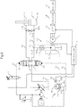
- the return oil from the rod-side hydraulic chamber 3b of the boom cylinder 3 is recirculated to the tank 18 via the line 6b and control valve 2.
- the return oil from the bottom-side hydraulic chamber 3a is recirculated to the tank 18 partly through the line 6a and control valve 2 and mostly via a regeneration circuit 21 of the power regeneration device 19.
- the line 6a will be referred to as the bottom-side line and the line 6b as the rod-side line.
- the make-up valves 22a and 22b are provided to prevent the lines 6a and 6b from developing a negative pressure causing cavitation.
- the make-up valve 22a or 22b opens to feed the hydraulic fluid to the line 6a or 6b.
- the make-up valve 22b also performs the role of supplying the rod-side hydraulic chamber 3b of the boom cylinder 3 with the hydraulic fluid from the tank 18 in the lowering operation of the boom 111.
- the power regeneration device 19 is made up of a line 6d, a pilot check valve 10, a fixed displacement hydraulic motor 11, an electric motor 12, an inverter 13, a chopper 14, an electric storage device (battery) 15, a pressure sensor 16, a rotation speed sensor 17, a proportional solenoid valve 7, and a controller (control device) 9.
- the hydraulic motor 11 is rotated by the return oil flowing thereto.
- the electric motor 12 coupled directly to the hydraulic motor 11 is thus rotated to perform a power generation operation.
- the generated electric energy is stored into the battery 15, whereby the power regeneration operation is carried out.
- this embodiment allows the hydraulic fluid to be evacuated in the amount corresponding to ⁇ Q from the bottom-side hydraulic chamber 3a of the boom cylinder 3 into the tank 18. As a result, it takes time t 3 for the amount of the hydraulic fluid discharged from the bottom-side hydraulic chamber 3a to reach the target flow rate Qo, the time t3 being shorter.
- the hydraulic motor 11 is rotated by the return oil discharged from the boom cylinder 3, causing the electric motor 12 directly coupled with the hydraulic motor 11 to perform a power generation operation.
- the generated electric power is stored into the battery 15, whereby the power regeneration operation is carried out.
Landscapes
- Engineering & Computer Science (AREA)
- General Engineering & Computer Science (AREA)
- Structural Engineering (AREA)
- Civil Engineering (AREA)
- Mining & Mineral Resources (AREA)
- Mechanical Engineering (AREA)
- Fluid Mechanics (AREA)
- Physics & Mathematics (AREA)
- Chemical & Material Sciences (AREA)
- Transportation (AREA)
- Analytical Chemistry (AREA)
- Life Sciences & Earth Sciences (AREA)
- Combustion & Propulsion (AREA)
- Geology (AREA)
- Power Engineering (AREA)
- Fluid-Pressure Circuits (AREA)
- Operation Control Of Excavators (AREA)
Claims (4)
- Arbeitsmaschine mit einem hydraulischen Stellglied (3, 114, 115) zum Antreiben einer Arbeitsvorrichtung (102), einem Steuerventil (2) zum Betätigen und Steuern des hydraulischen Stellglieds (3, 114, 115), einer Steuerhebelvorrichtung (4) mit einem Steuerhebel (4a) zum Betätigen des Steuerventils (2) zur Aktivierung des hydraulischen Stellglieds (3, 114, 115), und einer Stromrückgewinnungsvorrichtung (19), wobei die Stromrückgewinnungsvorrichtung (19) aufweist:einen hydraulischen Motor (11), der durch von dem hydraulischen Stellglied (3, 114, 115) zurückfließendes Öl angetrieben wird,einen elektrischen Motor (12), der mechanisch mit dem hydraulischen Motor (11) verbunden ist und von diesem angetrieben wird, um elektrischen Strom zu erzeugen,einen Wandler (13), der die Drehzahl des elektrischen Motors (12) steuert, undeine elektrische Speichervorrichtung (15), die den elektrischen Strom speichert, der von dem elektrischen Motor (12) erzeugt wird,wobei das zurückfließende Öl, das von dem hydraulischen Stellglied (3, 114, 115) abgegeben wird, zu der Seite des Steuerventils (2) und der Seite des hydraulischen Motors (11) abgezweigt und verteilt wird, wobei die Stromrückgewinnungsvorrichtung (19) ferner aufweist:einen Drehzahldetektor (17), der eine aktuelle Drehzahl des elektrischen Motors (12) erfasst,einen Betätigungsumfangsdetektor (16), der den Umfang der Betätigung des Steuerhebels (4a) erfasst,ein Proportionalmagnetventil (7), das die Öffnungsfläche des Steuerventils (2) anpasst, undeine Steuervorrichtung (9), in die die Drehzahl, die von dem Drehzahldetektor (17) erfasst wird, und der Betätigungsumfang, der von dem Betätigungsumfangsdetektor (16) erfasst wird, eingegeben werden,dadurch gekennzeichnet, dass die Steuervorrichtung (9) eine Sollströmungsrate des zurückgeführten Öls erhält, das von dem hydraulischen Stellglied (3, 114, 115) abgegeben wird, und eine Solldrehzahl des elektrischen Motors (12) auf der Grundlage des Betätigungsumfangs zur Steuerung der Drehzahl des elektrischen Motors (12) über den Wandler (13), derart, dass die Solldrehzahl des elektrischen Motors (12) erreicht wird, und wobei die Steuervorrichtung eine Abweichung zwischen der Sollströmungsrate Qo des zurückgeführten Öls, welches von der bodenseitigen hydraulischen Kammer des hydraulischen Stellglieds (3) abgegeben wird, und einer aktuellen Strömungsrate des Hydraulikfluids, welches durch den hydraulischen Motor (11) fließt, auf der Grundlage der aktuellen Drehzahl des Elektromotors (12) erhält, die von dem Drehzahldetektor (17) erfasst wird, und wobei die Steuervorrichtung das Proportionalmagnetventil (7) auf der Grundlage der erhaltenen Abweichung steuert.
- Arbeitsmaschine nach Anspruch 1, wobei die Steuervorrichtung (9) aufweist:eine Sollströmungsraten-Berechnungseinheit (31), die einen Betätigungsumfang empfängt und die Sollströmungsrate auf der Grundlage des empfangenen Betätigungsumfangs erhält,eine Solldrehzahl-Berechnungseinheit (32), die die Solldrehzahl über die erhaltene Sollströmungsrate erhält,eine Elektromotor-Steuerungswert-Berechnungseinheit (33), die ein Wandlersteuerungssignal für den Wandler (13) über die erhaltene Solldrehzahl erhält,eine Berechnungseinheit (34) einer aktuellen Strömungsrate, die die aktuelle Drehzahl empfängt und die aktuelle Strömungsrate auf der Grundlage der erhaltenen aktuellen Drehzahl erhält,eine Steuerventil-Sollströmungsraten-Berechnungseinheit (35), die die Abweichung zwischen der aktuellen Strömungsrate und der Sollströmungsrate erhält, und die erhaltene Abweichung als eine Sollströmungsrate für das Steuerventil liefert, undeine Proportionalmagnetventil-Steuerwert-Berechnungseinheit (36), die ein Steuersignal für das Proportionalmagnetventil (7) über die erhaltene Steuerventil-Sollströmungsrate erhält.
- Arbeitsmaschine nach Anspruch 1, wobei die Steuervorrichtung (9) aufweist:eine Sollströmungsraten-Berechnungseinheit (31), die den Betätigungsumfang empfängt und die Sollströmungsrate auf der Grundlage des erhaltenen Betätigungsumfangs erhält,eine Solldrehzahl-Berechnungseinheit (32), die die Solldrehzahl über die erhaltene Sollströmungsrate erhält,eine Elektromotor-Steuerwert-Berechnungseinheit (33), die ein Wandlersteuersignal für den Wandler (13) über die erhaltene Solldrehzahl erhält,eine Steuerventil-Sollströmungsraten-Berechnungseinheit (35A), die die aktuelle Drehzahl empfängt, eine Abweichung zwischen der Sollströmungsrate und der aktuellen Strömungsrate über eine Abweichung zwischen der Solldrehzahl, erhalten von der Solldrehzahl-Berechnungseinheit (32), und der aktuellen Drehzahl erhält, und die Abweichung liefert, die als eine Sollströmungsrate für das Steuerventil (2) erhalten wird, undeine Proportionalmagnetventil-Steuerungswert- Berechnungseinheit (36), die ein Steuersignal für das Proportionalmagnetventil (7) über die erhaltene Steuerventil-Sollströmungsrate erhält.
- Arbeitsmaschine nach einem der Ansprüche 1 bis 3, welche ferner ein Ein-/Aus-Ventil (23) aufweist, welches parallel zu dem Steuerventil (2) geschaltet ist, und zwischen der hydraulischen Pumpe (1) und der Hydraulikfluidzuführungsseite des hydraulischen Stellglieds (3, 114, 115) angeordnet ist, und welches in die geöffnete Stellung geschaltet wird, wenn der Steuerhebel (4a) der Steuerhebelvorrichtung (4) betätigt wird.
Applications Claiming Priority (2)
| Application Number | Priority Date | Filing Date | Title |
|---|---|---|---|
| JP2011289316 | 2011-12-28 | ||
| PCT/JP2012/082837 WO2013099710A1 (ja) | 2011-12-28 | 2012-12-18 | 作業機械の動力回生装置および作業機械 |
Publications (3)
| Publication Number | Publication Date |
|---|---|
| EP2799727A1 EP2799727A1 (de) | 2014-11-05 |
| EP2799727A4 EP2799727A4 (de) | 2016-01-20 |
| EP2799727B1 true EP2799727B1 (de) | 2018-05-30 |
Family
ID=48697202
Family Applications (1)
| Application Number | Title | Priority Date | Filing Date |
|---|---|---|---|
| EP12863748.5A Active EP2799727B1 (de) | 2011-12-28 | 2012-12-18 | Stromrückgewinnungsvorrichtung für eine arbeitsmaschine und arbeitsmaschine |
Country Status (6)
| Country | Link |
|---|---|
| US (1) | US9574328B2 (de) |
| EP (1) | EP2799727B1 (de) |
| JP (1) | JP6106097B2 (de) |
| KR (1) | KR101991983B1 (de) |
| CN (1) | CN104024659B (de) |
| WO (1) | WO2013099710A1 (de) |
Families Citing this family (21)
| Publication number | Priority date | Publication date | Assignee | Title |
|---|---|---|---|---|
| JP6019956B2 (ja) * | 2012-09-06 | 2016-11-02 | コベルコ建機株式会社 | ハイブリッド建設機械の動力制御装置 |
| JP6080458B2 (ja) * | 2012-09-28 | 2017-02-15 | 株式会社アイチコーポレーション | クローラ式走行車両 |
| JP2014118985A (ja) * | 2012-12-13 | 2014-06-30 | Kobelco Contstruction Machinery Ltd | 建設機械の油圧回路 |
| JP2016056808A (ja) * | 2013-01-29 | 2016-04-21 | 日立建機株式会社 | 作業機械の圧油エネルギ回収装置 |
| JP6286965B2 (ja) * | 2013-09-18 | 2018-03-07 | 株式会社豊田自動織機 | 産業車両の車速制御装置 |
| US10030361B2 (en) * | 2014-04-03 | 2018-07-24 | Hitachi Construction Machinery Co., Ltd. | Construction machine |
| WO2016051579A1 (ja) * | 2014-10-02 | 2016-04-07 | 日立建機株式会社 | 作業機械の油圧駆動システム |
| US10584722B2 (en) | 2015-09-29 | 2020-03-10 | Hitachi Construction Machinery Co., Ltd. | Hydraulic fluid energy regeneration apparatus of work machine |
| US10174770B2 (en) | 2015-11-09 | 2019-01-08 | Caterpillar Inc. | System and method of hydraulic energy recovery for machine start-stop and machine ride control |
| JP6360824B2 (ja) * | 2015-12-22 | 2018-07-18 | 日立建機株式会社 | 作業機械 |
| CN108869839B (zh) * | 2017-05-11 | 2020-06-05 | 上海汽车集团股份有限公司 | 流量变力电磁阀的流量补偿方法及装置 |
| CN107503998B (zh) * | 2017-09-15 | 2019-08-30 | 太原理工大学 | 背压及动力液压混合一体化调控多执行器系统 |
| CN107830002B (zh) * | 2017-10-27 | 2023-07-04 | 江苏徐工工程机械研究院有限公司 | 电液控制系统、方法及高空作业平台 |
| DE102017222761A1 (de) * | 2017-12-14 | 2019-06-19 | Robert Bosch Gmbh | Hydraulische Versorgungseinrichtung |
| JP7096105B2 (ja) * | 2018-08-23 | 2022-07-05 | 株式会社神戸製鋼所 | 掘削作業機械の油圧駆動装置 |
| KR102188638B1 (ko) * | 2019-02-08 | 2020-12-09 | 건설기계부품연구원 | 에너지 회생이 가능한 유압펌프의 가속수명시험을 위한 시험 장치 |
| CN113027839B (zh) * | 2021-02-23 | 2023-08-18 | 武汉船用机械有限责任公司 | 用于大吨位升降平台的液压控制系统 |
| CN116221199B (zh) * | 2021-12-06 | 2026-04-07 | 丹佛斯动力系统(江苏)有限公司 | 升降机构 |
| CA3164505A1 (en) | 2021-12-06 | 2023-06-06 | Danfoss Power Solutions (Jiangsu) Co., Ltd. | Lifting mechanism |
| CN114506799B (zh) * | 2022-04-20 | 2022-07-08 | 杭叉集团股份有限公司 | 一种叉车门架联合动作控制方法及控制系统 |
| WO2024201853A1 (ja) * | 2023-03-29 | 2024-10-03 | 日立建機株式会社 | 建設機械 |
Family Cites Families (17)
| Publication number | Priority date | Publication date | Assignee | Title |
|---|---|---|---|---|
| JP2000136806A (ja) * | 1998-11-04 | 2000-05-16 | Komatsu Ltd | 圧油のエネルギー回収装置および圧油のエネルギー回収・再生装置 |
| JP3877307B2 (ja) * | 2002-10-18 | 2007-02-07 | 株式会社小松製作所 | 圧油エネルギー回収装置 |
| JP2004324742A (ja) * | 2003-04-23 | 2004-11-18 | Saxa Inc | 液圧装置 |
| JP2006312995A (ja) * | 2005-05-09 | 2006-11-16 | Sumitomo (Shi) Construction Machinery Manufacturing Co Ltd | 作業機械のブームエネルギの回生装置及びエネルギの回生装置 |
| JP4879551B2 (ja) | 2005-10-13 | 2012-02-22 | 住友建機株式会社 | 作業機械のブームエネルギの回生装置及びエネルギの回生装置 |
| JP4871147B2 (ja) | 2007-01-15 | 2012-02-08 | 住友建機株式会社 | ブーム付き建設機械の油圧回路 |
| JP5078693B2 (ja) * | 2008-03-26 | 2012-11-21 | カヤバ工業株式会社 | ハイブリッド建設機械の制御装置 |
| CN101403405A (zh) * | 2008-10-31 | 2009-04-08 | 浙江大学 | 混合动力单泵多执行元件工程机械的能量回收系统 |
| CN101408213A (zh) * | 2008-11-11 | 2009-04-15 | 浙江大学 | 混合动力工程机械蓄能器-液压马达能量回收系统 |
| CN102549219B (zh) * | 2009-09-15 | 2015-02-25 | 住友重机械工业株式会社 | 混合式施工机械 |
| JP5600274B2 (ja) | 2010-08-18 | 2014-10-01 | 川崎重工業株式会社 | 作業機械の電液駆動システム |
| KR101787803B1 (ko) * | 2010-08-31 | 2017-10-18 | 히다찌 겐끼 가부시키가이샤 | 작업 기계 |
| JP2012097844A (ja) | 2010-11-02 | 2012-05-24 | Sumitomo (Shi) Construction Machinery Co Ltd | ハイブリッド油圧ショベル |
| CN102971542B (zh) * | 2011-02-03 | 2015-11-25 | 日立建机株式会社 | 作业机械的动力再生装置 |
| JP5642620B2 (ja) * | 2011-05-12 | 2014-12-17 | 日立建機株式会社 | 作業機械のエネルギ回生装置 |
| KR101928597B1 (ko) * | 2011-06-15 | 2018-12-12 | 히다찌 겐끼 가부시키가이샤 | 작업 기계의 동력 회생 장치 |
| JP5515087B2 (ja) * | 2011-06-15 | 2014-06-11 | 日立建機株式会社 | 作業機械の動力回生装置 |
-
2012
- 2012-12-18 KR KR1020147017351A patent/KR101991983B1/ko active Active
- 2012-12-18 CN CN201280064478.XA patent/CN104024659B/zh active Active
- 2012-12-18 JP JP2013551636A patent/JP6106097B2/ja active Active
- 2012-12-18 US US14/353,677 patent/US9574328B2/en active Active
- 2012-12-18 EP EP12863748.5A patent/EP2799727B1/de active Active
- 2012-12-18 WO PCT/JP2012/082837 patent/WO2013099710A1/ja not_active Ceased
Non-Patent Citations (1)
| Title |
|---|
| None * |
Also Published As
| Publication number | Publication date |
|---|---|
| KR20140105488A (ko) | 2014-09-01 |
| KR101991983B1 (ko) | 2019-06-21 |
| CN104024659B (zh) | 2016-04-27 |
| EP2799727A1 (de) | 2014-11-05 |
| JPWO2013099710A1 (ja) | 2015-05-07 |
| US20140283509A1 (en) | 2014-09-25 |
| EP2799727A4 (de) | 2016-01-20 |
| CN104024659A (zh) | 2014-09-03 |
| US9574328B2 (en) | 2017-02-21 |
| JP6106097B2 (ja) | 2017-03-29 |
| WO2013099710A1 (ja) | 2013-07-04 |
Similar Documents
| Publication | Publication Date | Title |
|---|---|---|
| EP2799727B1 (de) | Stromrückgewinnungsvorrichtung für eine arbeitsmaschine und arbeitsmaschine | |
| EP2685011B1 (de) | Schaufel und verfahren zur steuerung der schaufel | |
| US9518593B2 (en) | Hydraulic drive system for construction machine | |
| CN102741484B (zh) | 液压系统的泵控制装置 | |
| US8612102B2 (en) | Hydraulic excavator and hydraulic excavator control method | |
| CN104105888B (zh) | 工程机械 | |
| EP2918854B1 (de) | Hydraulische antriebsvorrichtung für eine baumaschine | |
| US10161108B2 (en) | Hydraulic fluid energy recovery system for work | |
| CN102971542B (zh) | 作业机械的动力再生装置 | |
| CN110462225B (zh) | 作业机械 | |
| KR102539054B1 (ko) | 유압 플라이휠 어큐뮬레이터, 유압 모터와 발전기를 이용한 에너지 회생 굴삭기 시스템 | |
| KR101747519B1 (ko) | 하이브리드식 건설 기계 | |
| KR101955751B1 (ko) | 건설 기계 | |
| EP3951086B1 (de) | Bagger | |
| EP4098810A1 (de) | Baumaschine | |
| US20250137232A1 (en) | Hydraulic Circuit for Construction Machine | |
| WO2021066029A1 (ja) | 建設機械 | |
| CN108286538B (zh) | 工程机械的液压系统 |
Legal Events
| Date | Code | Title | Description |
|---|---|---|---|
| PUAI | Public reference made under article 153(3) epc to a published international application that has entered the european phase |
Free format text: ORIGINAL CODE: 0009012 |
|
| 17P | Request for examination filed |
Effective date: 20140728 |
|
| AK | Designated contracting states |
Kind code of ref document: A1 Designated state(s): AL AT BE BG CH CY CZ DE DK EE ES FI FR GB GR HR HU IE IS IT LI LT LU LV MC MK MT NL NO PL PT RO RS SE SI SK SM TR |
|
| DAX | Request for extension of the european patent (deleted) | ||
| RA4 | Supplementary search report drawn up and despatched (corrected) |
Effective date: 20151222 |
|
| RIC1 | Information provided on ipc code assigned before grant |
Ipc: E02F 9/22 20060101ALI20151216BHEP Ipc: F15B 11/08 20060101ALI20151216BHEP Ipc: B66F 9/22 20060101ALI20151216BHEP Ipc: F15B 21/14 20060101AFI20151216BHEP Ipc: E02F 9/20 20060101ALI20151216BHEP Ipc: F15B 11/044 20060101ALI20151216BHEP |
|
| GRAP | Despatch of communication of intention to grant a patent |
Free format text: ORIGINAL CODE: EPIDOSNIGR1 |
|
| STAA | Information on the status of an ep patent application or granted ep patent |
Free format text: STATUS: GRANT OF PATENT IS INTENDED |
|
| INTG | Intention to grant announced |
Effective date: 20180202 |
|
| GRAS | Grant fee paid |
Free format text: ORIGINAL CODE: EPIDOSNIGR3 |
|
| GRAA | (expected) grant |
Free format text: ORIGINAL CODE: 0009210 |
|
| STAA | Information on the status of an ep patent application or granted ep patent |
Free format text: STATUS: THE PATENT HAS BEEN GRANTED |
|
| RAP1 | Party data changed (applicant data changed or rights of an application transferred) |
Owner name: HITACHI CONSTRUCTION MACHINERY CO., LTD. |
|
| AK | Designated contracting states |
Kind code of ref document: B1 Designated state(s): AL AT BE BG CH CY CZ DE DK EE ES FI FR GB GR HR HU IE IS IT LI LT LU LV MC MK MT NL NO PL PT RO RS SE SI SK SM TR |
|
| REG | Reference to a national code |
Ref country code: GB Ref legal event code: FG4D |
|
| REG | Reference to a national code |
Ref country code: CH Ref legal event code: EP |
|
| REG | Reference to a national code |
Ref country code: AT Ref legal event code: REF Ref document number: 1003895 Country of ref document: AT Kind code of ref document: T Effective date: 20180615 |
|
| REG | Reference to a national code |
Ref country code: IE Ref legal event code: FG4D |
|
| REG | Reference to a national code |
Ref country code: DE Ref legal event code: R096 Ref document number: 602012047063 Country of ref document: DE |
|
| REG | Reference to a national code |
Ref country code: NL Ref legal event code: MP Effective date: 20180530 |
|
| REG | Reference to a national code |
Ref country code: LT Ref legal event code: MG4D |
|
| PG25 | Lapsed in a contracting state [announced via postgrant information from national office to epo] |
Ref country code: NO Free format text: LAPSE BECAUSE OF FAILURE TO SUBMIT A TRANSLATION OF THE DESCRIPTION OR TO PAY THE FEE WITHIN THE PRESCRIBED TIME-LIMIT Effective date: 20180830 Ref country code: BG Free format text: LAPSE BECAUSE OF FAILURE TO SUBMIT A TRANSLATION OF THE DESCRIPTION OR TO PAY THE FEE WITHIN THE PRESCRIBED TIME-LIMIT Effective date: 20180830 Ref country code: FI Free format text: LAPSE BECAUSE OF FAILURE TO SUBMIT A TRANSLATION OF THE DESCRIPTION OR TO PAY THE FEE WITHIN THE PRESCRIBED TIME-LIMIT Effective date: 20180530 Ref country code: LT Free format text: LAPSE BECAUSE OF FAILURE TO SUBMIT A TRANSLATION OF THE DESCRIPTION OR TO PAY THE FEE WITHIN THE PRESCRIBED TIME-LIMIT Effective date: 20180530 Ref country code: SE Free format text: LAPSE BECAUSE OF FAILURE TO SUBMIT A TRANSLATION OF THE DESCRIPTION OR TO PAY THE FEE WITHIN THE PRESCRIBED TIME-LIMIT Effective date: 20180530 Ref country code: ES Free format text: LAPSE BECAUSE OF FAILURE TO SUBMIT A TRANSLATION OF THE DESCRIPTION OR TO PAY THE FEE WITHIN THE PRESCRIBED TIME-LIMIT Effective date: 20180530 Ref country code: CY Free format text: LAPSE BECAUSE OF FAILURE TO SUBMIT A TRANSLATION OF THE DESCRIPTION OR TO PAY THE FEE WITHIN THE PRESCRIBED TIME-LIMIT Effective date: 20180530 |
|
| PG25 | Lapsed in a contracting state [announced via postgrant information from national office to epo] |
Ref country code: RS Free format text: LAPSE BECAUSE OF FAILURE TO SUBMIT A TRANSLATION OF THE DESCRIPTION OR TO PAY THE FEE WITHIN THE PRESCRIBED TIME-LIMIT Effective date: 20180530 Ref country code: HR Free format text: LAPSE BECAUSE OF FAILURE TO SUBMIT A TRANSLATION OF THE DESCRIPTION OR TO PAY THE FEE WITHIN THE PRESCRIBED TIME-LIMIT Effective date: 20180530 Ref country code: GR Free format text: LAPSE BECAUSE OF FAILURE TO SUBMIT A TRANSLATION OF THE DESCRIPTION OR TO PAY THE FEE WITHIN THE PRESCRIBED TIME-LIMIT Effective date: 20180831 Ref country code: LV Free format text: LAPSE BECAUSE OF FAILURE TO SUBMIT A TRANSLATION OF THE DESCRIPTION OR TO PAY THE FEE WITHIN THE PRESCRIBED TIME-LIMIT Effective date: 20180530 |
|
| REG | Reference to a national code |
Ref country code: AT Ref legal event code: MK05 Ref document number: 1003895 Country of ref document: AT Kind code of ref document: T Effective date: 20180530 |
|
| PG25 | Lapsed in a contracting state [announced via postgrant information from national office to epo] |
Ref country code: NL Free format text: LAPSE BECAUSE OF FAILURE TO SUBMIT A TRANSLATION OF THE DESCRIPTION OR TO PAY THE FEE WITHIN THE PRESCRIBED TIME-LIMIT Effective date: 20180530 |
|
| PG25 | Lapsed in a contracting state [announced via postgrant information from national office to epo] |
Ref country code: PL Free format text: LAPSE BECAUSE OF FAILURE TO SUBMIT A TRANSLATION OF THE DESCRIPTION OR TO PAY THE FEE WITHIN THE PRESCRIBED TIME-LIMIT Effective date: 20180530 Ref country code: EE Free format text: LAPSE BECAUSE OF FAILURE TO SUBMIT A TRANSLATION OF THE DESCRIPTION OR TO PAY THE FEE WITHIN THE PRESCRIBED TIME-LIMIT Effective date: 20180530 Ref country code: AT Free format text: LAPSE BECAUSE OF FAILURE TO SUBMIT A TRANSLATION OF THE DESCRIPTION OR TO PAY THE FEE WITHIN THE PRESCRIBED TIME-LIMIT Effective date: 20180530 Ref country code: DK Free format text: LAPSE BECAUSE OF FAILURE TO SUBMIT A TRANSLATION OF THE DESCRIPTION OR TO PAY THE FEE WITHIN THE PRESCRIBED TIME-LIMIT Effective date: 20180530 Ref country code: CZ Free format text: LAPSE BECAUSE OF FAILURE TO SUBMIT A TRANSLATION OF THE DESCRIPTION OR TO PAY THE FEE WITHIN THE PRESCRIBED TIME-LIMIT Effective date: 20180530 Ref country code: RO Free format text: LAPSE BECAUSE OF FAILURE TO SUBMIT A TRANSLATION OF THE DESCRIPTION OR TO PAY THE FEE WITHIN THE PRESCRIBED TIME-LIMIT Effective date: 20180530 Ref country code: SK Free format text: LAPSE BECAUSE OF FAILURE TO SUBMIT A TRANSLATION OF THE DESCRIPTION OR TO PAY THE FEE WITHIN THE PRESCRIBED TIME-LIMIT Effective date: 20180530 |
|
| PG25 | Lapsed in a contracting state [announced via postgrant information from national office to epo] |
Ref country code: SM Free format text: LAPSE BECAUSE OF FAILURE TO SUBMIT A TRANSLATION OF THE DESCRIPTION OR TO PAY THE FEE WITHIN THE PRESCRIBED TIME-LIMIT Effective date: 20180530 Ref country code: IT Free format text: LAPSE BECAUSE OF FAILURE TO SUBMIT A TRANSLATION OF THE DESCRIPTION OR TO PAY THE FEE WITHIN THE PRESCRIBED TIME-LIMIT Effective date: 20180530 |
|
| REG | Reference to a national code |
Ref country code: DE Ref legal event code: R097 Ref document number: 602012047063 Country of ref document: DE |
|
| PLBE | No opposition filed within time limit |
Free format text: ORIGINAL CODE: 0009261 |
|
| STAA | Information on the status of an ep patent application or granted ep patent |
Free format text: STATUS: NO OPPOSITION FILED WITHIN TIME LIMIT |
|
| 26N | No opposition filed |
Effective date: 20190301 |
|
| PG25 | Lapsed in a contracting state [announced via postgrant information from national office to epo] |
Ref country code: SI Free format text: LAPSE BECAUSE OF FAILURE TO SUBMIT A TRANSLATION OF THE DESCRIPTION OR TO PAY THE FEE WITHIN THE PRESCRIBED TIME-LIMIT Effective date: 20180530 |
|
| REG | Reference to a national code |
Ref country code: CH Ref legal event code: PL |
|
| PG25 | Lapsed in a contracting state [announced via postgrant information from national office to epo] |
Ref country code: MC Free format text: LAPSE BECAUSE OF FAILURE TO SUBMIT A TRANSLATION OF THE DESCRIPTION OR TO PAY THE FEE WITHIN THE PRESCRIBED TIME-LIMIT Effective date: 20180530 Ref country code: LU Free format text: LAPSE BECAUSE OF NON-PAYMENT OF DUE FEES Effective date: 20181218 |
|
| REG | Reference to a national code |
Ref country code: IE Ref legal event code: MM4A |
|
| REG | Reference to a national code |
Ref country code: BE Ref legal event code: MM Effective date: 20181231 |
|
| PG25 | Lapsed in a contracting state [announced via postgrant information from national office to epo] |
Ref country code: IE Free format text: LAPSE BECAUSE OF NON-PAYMENT OF DUE FEES Effective date: 20181218 Ref country code: FR Free format text: LAPSE BECAUSE OF NON-PAYMENT OF DUE FEES Effective date: 20181231 |
|
| PG25 | Lapsed in a contracting state [announced via postgrant information from national office to epo] |
Ref country code: BE Free format text: LAPSE BECAUSE OF NON-PAYMENT OF DUE FEES Effective date: 20181231 Ref country code: AL Free format text: LAPSE BECAUSE OF FAILURE TO SUBMIT A TRANSLATION OF THE DESCRIPTION OR TO PAY THE FEE WITHIN THE PRESCRIBED TIME-LIMIT Effective date: 20180530 |
|
| PG25 | Lapsed in a contracting state [announced via postgrant information from national office to epo] |
Ref country code: LI Free format text: LAPSE BECAUSE OF NON-PAYMENT OF DUE FEES Effective date: 20181231 Ref country code: CH Free format text: LAPSE BECAUSE OF NON-PAYMENT OF DUE FEES Effective date: 20181231 |
|
| PG25 | Lapsed in a contracting state [announced via postgrant information from national office to epo] |
Ref country code: MT Free format text: LAPSE BECAUSE OF NON-PAYMENT OF DUE FEES Effective date: 20181218 |
|
| PG25 | Lapsed in a contracting state [announced via postgrant information from national office to epo] |
Ref country code: TR Free format text: LAPSE BECAUSE OF FAILURE TO SUBMIT A TRANSLATION OF THE DESCRIPTION OR TO PAY THE FEE WITHIN THE PRESCRIBED TIME-LIMIT Effective date: 20180530 |
|
| PG25 | Lapsed in a contracting state [announced via postgrant information from national office to epo] |
Ref country code: PT Free format text: LAPSE BECAUSE OF FAILURE TO SUBMIT A TRANSLATION OF THE DESCRIPTION OR TO PAY THE FEE WITHIN THE PRESCRIBED TIME-LIMIT Effective date: 20180530 |
|
| PG25 | Lapsed in a contracting state [announced via postgrant information from national office to epo] |
Ref country code: HU Free format text: LAPSE BECAUSE OF FAILURE TO SUBMIT A TRANSLATION OF THE DESCRIPTION OR TO PAY THE FEE WITHIN THE PRESCRIBED TIME-LIMIT; INVALID AB INITIO Effective date: 20121218 Ref country code: MK Free format text: LAPSE BECAUSE OF NON-PAYMENT OF DUE FEES Effective date: 20180530 |
|
| PG25 | Lapsed in a contracting state [announced via postgrant information from national office to epo] |
Ref country code: IS Free format text: LAPSE BECAUSE OF FAILURE TO SUBMIT A TRANSLATION OF THE DESCRIPTION OR TO PAY THE FEE WITHIN THE PRESCRIBED TIME-LIMIT Effective date: 20180930 |
|
| PGFP | Annual fee paid to national office [announced via postgrant information from national office to epo] |
Ref country code: DE Payment date: 20251028 Year of fee payment: 14 |
|
| PGFP | Annual fee paid to national office [announced via postgrant information from national office to epo] |
Ref country code: GB Payment date: 20251030 Year of fee payment: 14 |