EP2799771B1 - Brûleur à gaz, en particulier pour appareil de cuisson - Google Patents
Brûleur à gaz, en particulier pour appareil de cuisson Download PDFInfo
- Publication number
- EP2799771B1 EP2799771B1 EP14162488.2A EP14162488A EP2799771B1 EP 2799771 B1 EP2799771 B1 EP 2799771B1 EP 14162488 A EP14162488 A EP 14162488A EP 2799771 B1 EP2799771 B1 EP 2799771B1
- Authority
- EP
- European Patent Office
- Prior art keywords
- burner
- burners
- openings
- burners system
- cap
- Prior art date
- Legal status (The legal status is an assumption and is not a legal conclusion. Google has not performed a legal analysis and makes no representation as to the accuracy of the status listed.)
- Active
Links
Images

Classifications
-
- F—MECHANICAL ENGINEERING; LIGHTING; HEATING; WEAPONS; BLASTING
- F23—COMBUSTION APPARATUS; COMBUSTION PROCESSES
- F23D—BURNERS
- F23D14/00—Burners for combustion of a gas, e.g. of a gas stored under pressure as a liquid
- F23D14/02—Premix gas burners, i.e. in which gaseous fuel is mixed with combustion air upstream of the combustion zone
- F23D14/04—Premix gas burners, i.e. in which gaseous fuel is mixed with combustion air upstream of the combustion zone induction type, e.g. Bunsen burner
- F23D14/08—Premix gas burners, i.e. in which gaseous fuel is mixed with combustion air upstream of the combustion zone induction type, e.g. Bunsen burner with axial outlets at the burner head
-
- F—MECHANICAL ENGINEERING; LIGHTING; HEATING; WEAPONS; BLASTING
- F23—COMBUSTION APPARATUS; COMBUSTION PROCESSES
- F23D—BURNERS
- F23D14/00—Burners for combustion of a gas, e.g. of a gas stored under pressure as a liquid
- F23D14/02—Premix gas burners, i.e. in which gaseous fuel is mixed with combustion air upstream of the combustion zone
- F23D14/04—Premix gas burners, i.e. in which gaseous fuel is mixed with combustion air upstream of the combustion zone induction type, e.g. Bunsen burner
- F23D14/08—Premix gas burners, i.e. in which gaseous fuel is mixed with combustion air upstream of the combustion zone induction type, e.g. Bunsen burner with axial outlets at the burner head
- F23D14/085—Premix gas burners, i.e. in which gaseous fuel is mixed with combustion air upstream of the combustion zone induction type, e.g. Bunsen burner with axial outlets at the burner head with injector axis inclined to the burner head axis
-
- F—MECHANICAL ENGINEERING; LIGHTING; HEATING; WEAPONS; BLASTING
- F23—COMBUSTION APPARATUS; COMBUSTION PROCESSES
- F23D—BURNERS
- F23D14/00—Burners for combustion of a gas, e.g. of a gas stored under pressure as a liquid
- F23D14/46—Details
- F23D14/48—Nozzles
- F23D14/58—Nozzles characterised by the shape or arrangement of the outlet or outlets from the nozzle, e.g. of annular configuration
- F23D14/583—Nozzles characterised by the shape or arrangement of the outlet or outlets from the nozzle, e.g. of annular configuration of elongated shape, e.g. slits
-
- F—MECHANICAL ENGINEERING; LIGHTING; HEATING; WEAPONS; BLASTING
- F23—COMBUSTION APPARATUS; COMBUSTION PROCESSES
- F23D—BURNERS
- F23D2900/00—Special features of, or arrangements for burners using fluid fuels or solid fuels suspended in a carrier gas
- F23D2900/14—Special features of gas burners
- F23D2900/14062—Special features of gas burners for cooking ranges having multiple flame rings
Definitions
- This object of the present invention is a gas burner system, in particular for a food cooking appliance, according to preamble of claim 1.
- burner systems comprising two concentric burners, generally an outer burner and an inner burner, substantially of circular shape; such systems are known as burners like "double crown”.
- the two concentric burners may be fed by a single gas inlet duct, with its tap, which simultaneously feeds the different adduction ducts of the air-gas mixture to the concentric burners.
- US2007059657A1 and CN2911448Y disclose a burner system in which the first burner cap and said second burner cap, respectively, comprise a plurality of first openings and second elongated openings to allow the emission of gas in a direction inclined to the axis of the burners system, thereby generating flames which propagates in a substantially tangential direction from a visible surface of the hob.
- the burners systems of the known type propagate a flame known as “crown flame”; for “crown flame” means a flame having a substantially radial direction of propagation, namely that propagates from the gas burner to outside in a substantially radial direction relative to the burner axis, and then in a substantially tangential direction from a visible surface of the hob.
- This "crown flame” if it is emitted at a insufficient height compared to the cooking hob, produces a poor combustion in O2 and a resulting high generation of uncombusted (CO and NOx); furthermore, it usually causes deformations and / or blackening of the hob portion surrounding the burner, especially because of the heat contained in the flame..
- the flame which is emitted from the outermost openings of the burners system creates a sort of barrier for the secondary air which, consequently, is unable to adequately reach the innermost openings of the burners system , in particular of the inner burner; this will inevitably lead to poor combustion in O2 and a consequent high generation of incombusted gas.
- the present invention proposes to solve the above mentioned drawbacks and indicate a gas burner system for a food cooking appliance of improved and optimized realization compared to the known solutions.
- the main purpose of the this invention is to indicate a gas burners system, in particular for a food cooking appliance, provided with cheap and efficient means to allow a uniform air-gas mixture exit through the openings for the formation and propagation of the flame of the concentric burners.
- a further purpose of the this invention is to indicate a gas burners system , in particular for a food cooking appliance , that allows to reach a gas optimal efficiency allowing at the same time to contain the costs of realization of the burners system .
- a further purpose of this invention is to indicate a gas burner made in such a way that the secondary air can be achieved in a proper way the openings of both the outer burner and the inner burner.
- the object of the present invention is gas burners system, in particular for food cooking appliance, incorporating the features of the attached claims, which form an integral part of the present description.
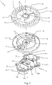
- the burners system 1 further comprises a couple of burners 10, 20 substantially concentric, said couple of burners 10, 20 comprising an outer burner 10 which has a first burner cap 11 and an inner burner 20 which has a second burner cap 21.
- first burner cap 11 is positioned on the outer burner 10
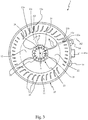
- second burner cap 21 is positioned on the inner burner 20; preferably, in a top view of the burner system 1 according to this invention (for example such as that referred to in Fig 3 ), the shape and size of said first burner cap 11 and second burner cap 21 are almost coincident respectively those of such external burner 10 and the inner burner 20.
- the first burner cap 11 is preferably formed in one piece suitable to be positioned on the outer burner 10; furthermore, the second burner cap 21 is preferably coupled to said first burner cap 11 through at least one arm 12, 22, in particular said at least one arm comprising a first arm 12 and a second arm 22 positioned substantially opposite sides from the second burner cap 21.
- said first burner cap 11 and said second burner cap 21 respectively comprise a plurality of first openings 13 and second openings 23 to allow the gas emission, said first openings 13 and second openings 23 being made so as to develop in a manner substantially parallel to the vertical axis A-A (as shown in Figures 1 and 2 by a dash-dot line and indicated by the reference A) of the burner 1.
- first openings 13 and the second openings 23 are particularly appreciable in a sectional view and when viewed in a direction substantially perpendicular to the axis A-A of the burner 1 (that is the view of Fig 2 ).
- said first openings 13 and second openings 23 are made in such a way as to generate a flame which propagates from the burners system 1 towards the outside in a direction substantially parallel with respect to said axis A-A of the burners system 1, said first openings 13 and second openings 23, therefore, being made in such a way to generate a "carpet flame".
- said first openings 13 of the first burner cap 11 are made in order to have an elongated shape when viewed in plan (for example when viewed in a substantially axial direction relative to the axis A-A of the burner 1).
- the first burner cap 11 is made in order to have a substantially circular shape when viewed in plan, and in particular with center A belonging to the axis A-A of the burner 1.
- each first opening 13 comprises a first portion 13a, a second portion 13b and an intermediate portion 13c, said second portion 13b being closer to the central burner 20 than said first portion 13a; accordingly, each first opening 13 is oriented substantially radially on said first burner cap 11.
- Each first opening 13 has a predominant direction of development along a second axis A2, in the orthogonal plane to the axis A-A, which preferably is inclined relatively to a radius R (in Fig 3 a plurality of rays R are indicated with a dotted line) of said first burner cap 11; this is equivalent to saying that said first portion 13a and second portion 13b of each first opening 13 each lie on a different ray R.
- the inclination of said second axis A2 with respect to the ray R is not particularly accentuated; this inclination is in fact comprised in a range between -30 ° and +30 °, preferably between -15 ° and +15 °, even more preferably between -10 ° and +10 °.
- first openings 13 are represented having predominant directions of development along said axis A2 not parallel to each other but inclined substantially with the same angle from the respective rays R; however, it is clear that the inclination of each first opening 13 can also be different.
- first openings 13 of the first burner cap 11 positioned in correspondence with said at least one arm 12, 22 are made in order to have the size smaller than the size of the remaining first openings 13 of the first burner cap 11.
- said remaining first openings 13 may include a second portion 13b made in such a way to have at least one portion inclined respect to the second axis A2 of said first opening 13; in particular, the first openings 13 which are not positioned in correspondence of said at least one arm 12, 22 comprise a second portion 13b which has said inclined portion with respect to the second axis A2. Consequently, said first openings 13 may have a shape of a "J" when viewed in plan (as can be seen from Fig 3 ).
- the particular conformation of said first openings 13 allows to favor the mixing of the mixture of primary air / gas with the secondary air necessary to reach optimum gas combustion.
- the second openings 23 of the second burner cap 21 are made in such a way to:
- the elongated shape of the said second openings 23 can also be different, for example a substantially elliptical shape.
- the second burner cap 21 is made in such a way to have a substantially circular shape when viewed in plan, said second openings 23 being oriented substantially radially on said second burner cap 21.
- the predictions of this invention allow to indicate a burners system 1 provided with cheap and efficient means to allow a uniform air-gas mixture exit through the openings 13,23 for the formation and propagation of the flame of the concentric burners 10, 20.
- the peculiar shape of said first openings 13 and second openings 23 is particularly advantageous both for the simplicity and convenience of their realization that allows to contain the costs of production methods of the burners system 1, both for their capability to reach an optimal efficiency of gas combustion.
- first openings 13 and second openings 23 allow to avoid the formation of a sort of barrier for the secondary air, which consequently is able to reach even the inner most positions of the first burner cap 10 and second burner cap 20, particularly in the presence of a possible container (not shown) positioned on the burner system 1, the container which could contribute to make difficult the flowing of the secondary air.
- first the burner cap 11 and / or the second burner cap 21, may then comprise a plurality of secondary openings (not shown in the figures) for the flame propagation, in particular each secondary opening being preferably positioned between a couple of said first openings 13 and / or second openings 23.
- the burners system 1 comprises:
- the primary air is taken above a cooking hob 2 (visible in Fig 2 ) on which is mounted said burners system 1.
- the primary air is sucked through passages 3 formed on a side surface of the outer burner 10 and positioned on opposite sides from the axis A of said burner system 1.
- the fact to withdraw the primary air above the cooking hob 2 allows to avoid some drawbacks that frequently occur in cases where the primary air is sucked below of a cooking hob; these drawbacks are caused both by any disturbance of the air flow, for example due to the opening and closing of the furniture doors to the underlying burners system 1, both the primary air pollution due to the possible presence of a cooking oven in the spaces below said burners system 1.
- the primary air suction above the cooking hob 2 allows to encrease mainly the aeration of the burners system 1 maintaining at the same time reduced the height of the burners system 1.
- said at least one chamber 51, 52, 53 with the Venturi effect is positioned in such a way to receive a gas-air mixture (formed within said at least one cup 31, 32, 33) coming from said at least one cup 31, 32, 33 and to direct the air-gas mixture flow to the first openings 13 of the first burner cap 11 and to the second openings 23 of the second burner cap 21.
- the lower body 30 comprises a number of cups 31, 32, 33 corresponding to the number of chambers 51, 52, 53 with the Venturi effect of the burner body 50.
- the burners system 1 comprises:
- the burners system 1, according to the this invention can be realized in such a way to comprise a different number of burner cups 31, 32, 33, and chambers 51, 52, 53 with the Venturi effect.
- the burner body 50 is preferably formed in one piece comprising the first chamber 51, the second chamber 52 and third chamber 53, in particular said burner body 50 having a shape (if it viewed in the plan) substantially corresponding to that of the whole constituted by the first burner cap 11 and second burner cap 21.
- the burner body 50 includes first walls 54 designed to keep separated the area surrounding the third chamber 53 from the areas surrounding the first chamber 51 and second chamber 52; this prevision allows to direct in an optimal manner the air-gas mixture coming from the third chamber 53 to the second openings 23 of the second burner cap 21.
- the burner body 50 may comprise second walls 55 designed to keep separate the areas surrounding the first chamber 51 and second chamber 52 from the outside, in order to optimally direct the air-gas mixture from said first chamber 51 and second chamber 52 to the first openings 13 of the first burner cap 11.
- the first burner cap 11 and the second burner cap 21 are formed in a single piece of sintered steel; the lower body 30 and the burner body 50 are then preferably made of die-cast aluminum.
- said supply means 40 comprise at least a duct 41a, 41b to supply the burners system 1.
- said at least one duct 41a, 41b includes:
- said burners system 1 may also comprise a single duct that supplies simultaneously the different adduction ducts of the air-gas mixture to the burners 10, 20.
- the burners system 1 comprises coupling means 14 and / or some shaped portions 24 adapted to allow the passage of at least a spark plug and / or at least one thermocouple (not shown in the figures).
- the previsions of this invention allow to indicate a burners system 1 provided with cheap and efficient means in order to allow a uniform exit of the air-gas mixture through the openings 13, 23 for the formation and propagation of the flame of the concentric burners 10, 20.
- first openings 13 and second openings 23 are particularly advantageous both for the simplicity and convenience of their realization (which also allows to contain the costs of production method of the burners system 1), and for their capability to obtain optimum efficiency of the gas combustion.
- first openings 13 and second openings 23 allow to avoid the formation of a sort of barrier for the secondary air, which is consequently good to reach even the inner most portions of the first burner cap 10 and second burner cap 20, particularly in presence of a possible container (not shown) positioned on the gas burners system 1, container which could contribute to make difficult the passage of the secondary air.
- the suction of the primary air above the cooking hob 2 allows increase mainly the aeration of the burners system 1 maintaining at the same time reduced the height of the burners system 1.
- the previsions of this invention allow to indicate a burners system 1 realized in such a way the outer burner 10 and the inner burner 20 can be used jointly or separately; this allows to reach a good variability and a homogeneous distribution of heat which must be supplied to a cooking container .
Landscapes
- Engineering & Computer Science (AREA)
- Chemical & Material Sciences (AREA)
- Combustion & Propulsion (AREA)
- Mechanical Engineering (AREA)
- General Engineering & Computer Science (AREA)
- Gas Burners (AREA)
- Feeding And Controlling Fuel (AREA)
Claims (11)
- Système de brûleurs à gaz (1) pour une application de cuisson d'aliments, ledit système de brûleurs (1) comprenant un couple de brûleurs (10, 20) sensiblement concentriques, ledit couple de brûleurs (10, 20) comprenant un brûleur extérieur (10) muni d'un premier chapeau de brûleur (11) et un brûleur intérieur (20) muni d'un second chapeau de brûleur (21),
ledit premier chapeau de brûleur (11) et ledit second chapeau de brûleur (21) comprenant respectivement une pluralité de premières ouvertures (13) et de secondes ouvertures (23) pour permettre l'émission de gaz,
ledit premier chapeau de brûleur (11) présente une forme sensiblement circulaire lorsque vu en plan et chaque première ouverture (13) présente une forme allongée lorsque vue en plan,
dans lequel chaque première ouverture (13) comprend une première partie (13a), une deuxième partie (13b) et une partie intermédiaire (13c), ladite deuxième partie (13b) étant plus proche du brûleur central (20) que ladite première partie (13a),
et dans lequel chaque première ouverture (13) est orientée sensiblement de manière radiale sur ledit premier chapeau de brûleur (11),
caractérisé en ce que le système de brûleurs (1) comprend des passages (3) formés sur une surface latérale du brûleur extérieur (10), en particulier lesdits passages (3) étant positionnés sur des côtés opposés par rapport à un axe vertical (A-A) dudit système de brûleurs (1), lesdits passages permettant d'aspirer l'air primaire au-dessus d'une plaque de cuisson (2), et en ce que
lesdites premières ouvertures (13) et secondes ouvertures (23) se développent dans une direction sensiblement parallèle à l'axe vertical (A-A) du système de brûleurs (1) pour générer une flamme qui se propage depuis le système de brûleurs (1) vers l'extérieur dans ladite direction sensiblement parallèle audit axe (A-A) du système de brûleurs (1). - Système de brûleurs (1) selon la revendication 1, caractérisé en ce que chaque première ouverture (13) est inclinée par rapport à un rayon (R) dudit premier chapeau de brûleur (11).
- Système de brûleurs (1) selon une ou plusieurs des revendications précédentes, caractérisé en ce que le second chapeau de brûleur (21) est couplé audit premier chapeau de brûleur (11) par au moins un bras (12, 22), en particulier ledit au moins un bras comprenant un premier bras (12) et un second bras (22) positionnés sur des côtés sensiblement opposés du second chapeau de brûleur (21).
- Système de brûleurs (1) selon la revendication 3, caractérisé en ce que les premières ouvertures (13) du premier chapeau de brûleur (11) positionnées en correspondance dudit au moins un bras (12, 22) sont faites dans le but d'avoir la taille plus petite comparée à la taille des premières ouvertures restantes (13) du premier chapeau de brûleur (13).
- Système de brûleurs (1) selon une ou plusieurs des revendications précédentes, caractérisé en ce que lesdites premières ouvertures (13) comprennent une deuxième partie (13b) présentant au moins une partie inclinée par rapport à un second axe (A2) de développement prédominant de ladite première ouverture (13).
- Système de brûleurs (1) selon une ou plusieurs des revendications précédentes, caractérisé en ce que lesdites secondes ouvertures (23) du second chapeau de brûleur (21) présentent une forme allongée lorsque vues en plan, en particulier les secondes ouvertures (23) présentant une forme sensiblement rectangulaire.
- Système de brûleurs (1) selon une ou plusieurs des revendications précédentes, caractérisé en ce que ledit second chapeau de brûleur (21) est réalisé pour présenter une forme sensiblement circulaire lorsque vu en plan, lesdites secondes ouvertures (23) étant orientées sensiblement radialement sur ledit second chapeau de brûleur (21).
- Système de brûleurs (1) selon une ou plusieurs des revendications précédentes, caractérisé en ce qu'il comprend :- un corps inférieur (30) comprenant au moins une coupelle de brûleur (31, 32, 33) associée à des moyens d'alimentation (40) pour une alimentation en gaz vers ledit système de brûleurs (1) ;- un corps de brûleur (50) comprenant au moins une chambre (51, 52, 53) avec l'effet Venturi qui se développe sensiblement verticalement au-dessus de ladite coupelle de brûleur (31, 32, 33).
- Système de brûleurs (1) selon la revendication 8, caractérisé en ce que le corps inférieur (30) comprend un nombre de coupelles de brûleur (31, 32, 33) correspondant au nombre de chambres (51, 52, 53) avec effet Venturi du corps de brûleur (50), en particulier le système de brûleurs (1) comprenant :- une première coupelle de brûleur (31) et une deuxième coupelle de brûleur (32) associées respectivement à une première chambre (51) et à une deuxième chambre (52) du corps de brûleur (50) pour alimenter le brûleur extérieur (10) ;- une troisième coupelle de brûleur (33) associée à une troisième chambre (53) pour alimenter le brûleur intérieur (20).
- Système de brûleurs (1) selon la revendication 9, caractérisé en ce que ledit corps de brûleur (50) inclut :- des premières parois (54) conçues pour maintenir la zone entourant la troisième chambre (53) séparée des zones entourant la première chambre (51) et la deuxième chambre (52), et/ou ;- des secondes parois (55) conçues pour maintenir les zones entourant la première chambre (51) et la deuxième chambre (52) séparées de l'extérieur.
- Système de brûleurs (1) selon une ou plusieurs des revendications précédentes, caractérisé en ce qu'il comprend des moyens d'alimentation (40) comprenant au moins un conduit (41a, 41b) pour alimenter le système de brûleurs (1), en particulier ledit au moins un conduit (41a, 41b) comprenant :- un premier conduit (41a) pour alimenter le brûleur extérieur (10), en particulier ledit premier conduit (41a) étant relié à la première coupelle de brûleur (31) à travers un premier gicleur (42a) et à la deuxième coupelle de brûleur (32) à travers un deuxième gicleur (42b) ;- un second conduit (41b) pour alimenter le brûleur intérieur (20), en particulier ledit second conduit (41b) étant relié à la troisième coupelle de brûleur (33) à travers un troisième gicleur (42c).
Applications Claiming Priority (1)
| Application Number | Priority Date | Filing Date | Title |
|---|---|---|---|
| IT000070U ITTO20130070U1 (it) | 2013-04-29 | 2013-04-29 | Sistema di bruciatori di gas, in particolare per un apparecchio di cottura per alimenti |
Publications (3)
| Publication Number | Publication Date |
|---|---|
| EP2799771A2 EP2799771A2 (fr) | 2014-11-05 |
| EP2799771A3 EP2799771A3 (fr) | 2014-12-03 |
| EP2799771B1 true EP2799771B1 (fr) | 2021-04-21 |
Family
ID=49485396
Family Applications (1)
| Application Number | Title | Priority Date | Filing Date |
|---|---|---|---|
| EP14162488.2A Active EP2799771B1 (fr) | 2013-04-29 | 2014-03-28 | Brûleur à gaz, en particulier pour appareil de cuisson |
Country Status (3)
| Country | Link |
|---|---|
| EP (1) | EP2799771B1 (fr) |
| IT (1) | ITTO20130070U1 (fr) |
| RU (1) | RU2014117183A (fr) |
Families Citing this family (6)
| Publication number | Priority date | Publication date | Assignee | Title |
|---|---|---|---|---|
| NL2011286C2 (nl) * | 2013-08-09 | 2015-02-10 | Intell Properties B V | Gasbrander |
| EP3056810B1 (fr) * | 2015-02-11 | 2019-04-10 | Electrolux Appliances Aktiebolag | Ensemble à brûleur de gaz |
| WO2016145746A1 (fr) * | 2015-03-13 | 2016-09-22 | 广东美的厨房电器制造有限公司 | Brûleur et appareil à gaz |
| CN106224962A (zh) * | 2016-08-30 | 2016-12-14 | 宁波方太厨具有限公司 | 一种燃烧器火盖 |
| US10436451B2 (en) * | 2016-10-06 | 2019-10-08 | Whirlpool Corporation | Cap to change inner flame burner to vertical flame |
| CN113375156B (zh) * | 2021-06-10 | 2022-07-05 | 宁波方太厨具有限公司 | 火盖及包含其的灶具燃烧器 |
Citations (3)
| Publication number | Priority date | Publication date | Assignee | Title |
|---|---|---|---|---|
| FR786709A (fr) * | 1935-02-25 | 1935-09-09 | Foyer de fourneaux à gaz à simple et double feux | |
| US20070059657A1 (en) * | 2005-09-15 | 2007-03-15 | Chia-Hsi Yen | Gas burner |
| KR20100122365A (ko) * | 2009-05-12 | 2010-11-22 | 박명선 | 서브 버너 헤드 조립식 조리용 가스버너 |
Family Cites Families (4)
| Publication number | Priority date | Publication date | Assignee | Title |
|---|---|---|---|---|
| IT1232887B (it) * | 1989-07-27 | 1992-03-05 | Merloni Elettrodomestici Spa | Bruciatore di gas per cottura di alimenti |
| HU227511B1 (hu) | 2002-11-12 | 2011-07-28 | Sabaf Spa | Gázégõ gáztûzhelyekhez |
| CN2911448Y (zh) * | 2006-05-08 | 2007-06-13 | 湖南迅达集团有限公司 | 整体式双火头燃烧盘 |
| DE102006051286A1 (de) * | 2006-10-26 | 2008-04-30 | Deutsches Zentrum für Luft- und Raumfahrt e.V. | Brennervorrichtung |
-
2013
- 2013-04-29 IT IT000070U patent/ITTO20130070U1/it unknown
-
2014
- 2014-03-28 EP EP14162488.2A patent/EP2799771B1/fr active Active
- 2014-04-28 RU RU2014117183/06A patent/RU2014117183A/ru not_active Application Discontinuation
Patent Citations (3)
| Publication number | Priority date | Publication date | Assignee | Title |
|---|---|---|---|---|
| FR786709A (fr) * | 1935-02-25 | 1935-09-09 | Foyer de fourneaux à gaz à simple et double feux | |
| US20070059657A1 (en) * | 2005-09-15 | 2007-03-15 | Chia-Hsi Yen | Gas burner |
| KR20100122365A (ko) * | 2009-05-12 | 2010-11-22 | 박명선 | 서브 버너 헤드 조립식 조리용 가스버너 |
Also Published As
| Publication number | Publication date |
|---|---|
| EP2799771A3 (fr) | 2014-12-03 |
| ITTO20130070U1 (it) | 2014-10-30 |
| EP2799771A2 (fr) | 2014-11-05 |
| RU2014117183A (ru) | 2015-11-10 |
Similar Documents
| Publication | Publication Date | Title |
|---|---|---|
| EP2799771B1 (fr) | Brûleur à gaz, en particulier pour appareil de cuisson | |
| US8746229B2 (en) | Gas burner system for food cooking appliances | |
| US10145568B2 (en) | High efficiency high power inner flame burner | |
| US10317088B2 (en) | Triple ring flame burner | |
| ES2389998T3 (es) | Encimera de cocción con quemador de gas mejorado | |
| CN103388843B (zh) | 一种节能环保燃烧器 | |
| US11421889B2 (en) | Cap to change inner flame burner to vertical flame | |
| US11441781B2 (en) | System of gas burners, in particular for a cooking top for household use | |
| US20100154776A1 (en) | Cooking range burner head assembly | |
| US20130092149A1 (en) | Delta burner | |
| US10393386B2 (en) | System of gas burners, in particular for a cooking top for household use | |
| EP2737250A2 (fr) | Brûleur à gaz, en particulier pour un appareil de cuisson d'aliments | |
| US20170023245A1 (en) | Dual ring burner ovni | |
| TR201906118T4 (tr) | Mutfak ocağı için gaz brülörü. | |
| US20190331337A1 (en) | Gas burner and hob comprising a gas burner | |
| US20060147865A1 (en) | Cooking range burner head assembly | |
| US10605462B2 (en) | Main top of a cooktop appliance | |
| CN217356879U (zh) | 带有引射混合系统的燃烧器及燃气灶 | |
| WO2018153858A1 (fr) | Ensemble brûleur | |
| US10928061B2 (en) | Gas burner and hob comprising a gas burner | |
| US20170038076A1 (en) | Gas burner, in particular for a cooking top for household use | |
| US20110265782A1 (en) | Cooking range burner arrangement | |
| EP3775686B1 (fr) | Ensemble brûleur à gaz | |
| KR101751059B1 (ko) | 빌트인 타입 가스오븐레인지 | |
| WO2023101634A1 (fr) | Brûleur à gaz multiples pour augmenter l'efficacité |
Legal Events
| Date | Code | Title | Description |
|---|---|---|---|
| PUAL | Search report despatched |
Free format text: ORIGINAL CODE: 0009013 |
|
| PUAI | Public reference made under article 153(3) epc to a published international application that has entered the european phase |
Free format text: ORIGINAL CODE: 0009012 |
|
| 17P | Request for examination filed |
Effective date: 20140328 |
|
| AK | Designated contracting states |
Kind code of ref document: A2 Designated state(s): AL AT BE BG CH CY CZ DE DK EE ES FI FR GB GR HR HU IE IS IT LI LT LU LV MC MK MT NL NO PL PT RO RS SE SI SK SM TR |
|
| AX | Request for extension of the european patent |
Extension state: BA ME |
|
| AK | Designated contracting states |
Kind code of ref document: A3 Designated state(s): AL AT BE BG CH CY CZ DE DK EE ES FI FR GB GR HR HU IE IS IT LI LT LU LV MC MK MT NL NO PL PT RO RS SE SI SK SM TR |
|
| AX | Request for extension of the european patent |
Extension state: BA ME |
|
| RIC1 | Information provided on ipc code assigned before grant |
Ipc: F23D 14/08 20060101AFI20141029BHEP Ipc: F23D 14/58 20060101ALI20141029BHEP |
|
| R17P | Request for examination filed (corrected) |
Effective date: 20150603 |
|
| RBV | Designated contracting states (corrected) |
Designated state(s): AL AT BE BG CH CY CZ DE DK EE ES FI FR GB GR HR HU IE IS IT LI LT LU LV MC MK MT NL NO PL PT RO RS SE SI SK SM TR |
|
| RAP1 | Party data changed (applicant data changed or rights of an application transferred) |
Owner name: WHIRLPOOL EMEA S.P.A |
|
| STAA | Information on the status of an ep patent application or granted ep patent |
Free format text: STATUS: EXAMINATION IS IN PROGRESS |
|
| 17Q | First examination report despatched |
Effective date: 20170313 |
|
| RIC1 | Information provided on ipc code assigned before grant |
Ipc: F23D 14/08 20060101AFI20190402BHEP |
|
| GRAP | Despatch of communication of intention to grant a patent |
Free format text: ORIGINAL CODE: EPIDOSNIGR1 |
|
| STAA | Information on the status of an ep patent application or granted ep patent |
Free format text: STATUS: GRANT OF PATENT IS INTENDED |
|
| GRAS | Grant fee paid |
Free format text: ORIGINAL CODE: EPIDOSNIGR3 |
|
| INTG | Intention to grant announced |
Effective date: 20210127 |
|
| GRAA | (expected) grant |
Free format text: ORIGINAL CODE: 0009210 |
|
| STAA | Information on the status of an ep patent application or granted ep patent |
Free format text: STATUS: THE PATENT HAS BEEN GRANTED |
|
| AK | Designated contracting states |
Kind code of ref document: B1 Designated state(s): AL AT BE BG CH CY CZ DE DK EE ES FI FR GB GR HR HU IE IS IT LI LT LU LV MC MK MT NL NO PL PT RO RS SE SI SK SM TR |
|
| REG | Reference to a national code |
Ref country code: GB Ref legal event code: FG4D |
|
| REG | Reference to a national code |
Ref country code: CH Ref legal event code: EP |
|
| REG | Reference to a national code |
Ref country code: DE Ref legal event code: R096 Ref document number: 602014076720 Country of ref document: DE Ref country code: IE Ref legal event code: FG4D |
|
| REG | Reference to a national code |
Ref country code: AT Ref legal event code: REF Ref document number: 1385009 Country of ref document: AT Kind code of ref document: T Effective date: 20210515 |
|
| REG | Reference to a national code |
Ref country code: LT Ref legal event code: MG9D |
|
| REG | Reference to a national code |
Ref country code: AT Ref legal event code: MK05 Ref document number: 1385009 Country of ref document: AT Kind code of ref document: T Effective date: 20210421 |
|
| REG | Reference to a national code |
Ref country code: NL Ref legal event code: MP Effective date: 20210421 |
|
| PG25 | Lapsed in a contracting state [announced via postgrant information from national office to epo] |
Ref country code: AT Free format text: LAPSE BECAUSE OF FAILURE TO SUBMIT A TRANSLATION OF THE DESCRIPTION OR TO PAY THE FEE WITHIN THE PRESCRIBED TIME-LIMIT Effective date: 20210421 Ref country code: BG Free format text: LAPSE BECAUSE OF FAILURE TO SUBMIT A TRANSLATION OF THE DESCRIPTION OR TO PAY THE FEE WITHIN THE PRESCRIBED TIME-LIMIT Effective date: 20210721 Ref country code: FI Free format text: LAPSE BECAUSE OF FAILURE TO SUBMIT A TRANSLATION OF THE DESCRIPTION OR TO PAY THE FEE WITHIN THE PRESCRIBED TIME-LIMIT Effective date: 20210421 Ref country code: LT Free format text: LAPSE BECAUSE OF FAILURE TO SUBMIT A TRANSLATION OF THE DESCRIPTION OR TO PAY THE FEE WITHIN THE PRESCRIBED TIME-LIMIT Effective date: 20210421 Ref country code: NL Free format text: LAPSE BECAUSE OF FAILURE TO SUBMIT A TRANSLATION OF THE DESCRIPTION OR TO PAY THE FEE WITHIN THE PRESCRIBED TIME-LIMIT Effective date: 20210421 Ref country code: HR Free format text: LAPSE BECAUSE OF FAILURE TO SUBMIT A TRANSLATION OF THE DESCRIPTION OR TO PAY THE FEE WITHIN THE PRESCRIBED TIME-LIMIT Effective date: 20210421 |
|
| PG25 | Lapsed in a contracting state [announced via postgrant information from national office to epo] |
Ref country code: GR Free format text: LAPSE BECAUSE OF FAILURE TO SUBMIT A TRANSLATION OF THE DESCRIPTION OR TO PAY THE FEE WITHIN THE PRESCRIBED TIME-LIMIT Effective date: 20210722 Ref country code: LV Free format text: LAPSE BECAUSE OF FAILURE TO SUBMIT A TRANSLATION OF THE DESCRIPTION OR TO PAY THE FEE WITHIN THE PRESCRIBED TIME-LIMIT Effective date: 20210421 Ref country code: IS Free format text: LAPSE BECAUSE OF FAILURE TO SUBMIT A TRANSLATION OF THE DESCRIPTION OR TO PAY THE FEE WITHIN THE PRESCRIBED TIME-LIMIT Effective date: 20210821 Ref country code: PT Free format text: LAPSE BECAUSE OF FAILURE TO SUBMIT A TRANSLATION OF THE DESCRIPTION OR TO PAY THE FEE WITHIN THE PRESCRIBED TIME-LIMIT Effective date: 20210823 Ref country code: PL Free format text: LAPSE BECAUSE OF FAILURE TO SUBMIT A TRANSLATION OF THE DESCRIPTION OR TO PAY THE FEE WITHIN THE PRESCRIBED TIME-LIMIT Effective date: 20210421 Ref country code: NO Free format text: LAPSE BECAUSE OF FAILURE TO SUBMIT A TRANSLATION OF THE DESCRIPTION OR TO PAY THE FEE WITHIN THE PRESCRIBED TIME-LIMIT Effective date: 20210721 Ref country code: ES Free format text: LAPSE BECAUSE OF FAILURE TO SUBMIT A TRANSLATION OF THE DESCRIPTION OR TO PAY THE FEE WITHIN THE PRESCRIBED TIME-LIMIT Effective date: 20210421 Ref country code: SE Free format text: LAPSE BECAUSE OF FAILURE TO SUBMIT A TRANSLATION OF THE DESCRIPTION OR TO PAY THE FEE WITHIN THE PRESCRIBED TIME-LIMIT Effective date: 20210421 Ref country code: RS Free format text: LAPSE BECAUSE OF FAILURE TO SUBMIT A TRANSLATION OF THE DESCRIPTION OR TO PAY THE FEE WITHIN THE PRESCRIBED TIME-LIMIT Effective date: 20210421 |
|
| REG | Reference to a national code |
Ref country code: DE Ref legal event code: R097 Ref document number: 602014076720 Country of ref document: DE |
|
| PG25 | Lapsed in a contracting state [announced via postgrant information from national office to epo] |
Ref country code: EE Free format text: LAPSE BECAUSE OF FAILURE TO SUBMIT A TRANSLATION OF THE DESCRIPTION OR TO PAY THE FEE WITHIN THE PRESCRIBED TIME-LIMIT Effective date: 20210421 Ref country code: DK Free format text: LAPSE BECAUSE OF FAILURE TO SUBMIT A TRANSLATION OF THE DESCRIPTION OR TO PAY THE FEE WITHIN THE PRESCRIBED TIME-LIMIT Effective date: 20210421 Ref country code: CZ Free format text: LAPSE BECAUSE OF FAILURE TO SUBMIT A TRANSLATION OF THE DESCRIPTION OR TO PAY THE FEE WITHIN THE PRESCRIBED TIME-LIMIT Effective date: 20210421 Ref country code: SK Free format text: LAPSE BECAUSE OF FAILURE TO SUBMIT A TRANSLATION OF THE DESCRIPTION OR TO PAY THE FEE WITHIN THE PRESCRIBED TIME-LIMIT Effective date: 20210421 Ref country code: SM Free format text: LAPSE BECAUSE OF FAILURE TO SUBMIT A TRANSLATION OF THE DESCRIPTION OR TO PAY THE FEE WITHIN THE PRESCRIBED TIME-LIMIT Effective date: 20210421 Ref country code: RO Free format text: LAPSE BECAUSE OF FAILURE TO SUBMIT A TRANSLATION OF THE DESCRIPTION OR TO PAY THE FEE WITHIN THE PRESCRIBED TIME-LIMIT Effective date: 20210421 |
|
| PLBE | No opposition filed within time limit |
Free format text: ORIGINAL CODE: 0009261 |
|
| STAA | Information on the status of an ep patent application or granted ep patent |
Free format text: STATUS: NO OPPOSITION FILED WITHIN TIME LIMIT |
|
| 26N | No opposition filed |
Effective date: 20220124 |
|
| PG25 | Lapsed in a contracting state [announced via postgrant information from national office to epo] |
Ref country code: IS Free format text: LAPSE BECAUSE OF FAILURE TO SUBMIT A TRANSLATION OF THE DESCRIPTION OR TO PAY THE FEE WITHIN THE PRESCRIBED TIME-LIMIT Effective date: 20210821 Ref country code: AL Free format text: LAPSE BECAUSE OF FAILURE TO SUBMIT A TRANSLATION OF THE DESCRIPTION OR TO PAY THE FEE WITHIN THE PRESCRIBED TIME-LIMIT Effective date: 20210421 |
|
| PG25 | Lapsed in a contracting state [announced via postgrant information from national office to epo] |
Ref country code: MC Free format text: LAPSE BECAUSE OF FAILURE TO SUBMIT A TRANSLATION OF THE DESCRIPTION OR TO PAY THE FEE WITHIN THE PRESCRIBED TIME-LIMIT Effective date: 20210421 |
|
| REG | Reference to a national code |
Ref country code: CH Ref legal event code: PL |
|
| REG | Reference to a national code |
Ref country code: BE Ref legal event code: MM Effective date: 20220331 |
|
| PG25 | Lapsed in a contracting state [announced via postgrant information from national office to epo] |
Ref country code: LU Free format text: LAPSE BECAUSE OF NON-PAYMENT OF DUE FEES Effective date: 20220328 Ref country code: LI Free format text: LAPSE BECAUSE OF NON-PAYMENT OF DUE FEES Effective date: 20220331 Ref country code: IE Free format text: LAPSE BECAUSE OF NON-PAYMENT OF DUE FEES Effective date: 20220328 Ref country code: CH Free format text: LAPSE BECAUSE OF NON-PAYMENT OF DUE FEES Effective date: 20220331 |
|
| PG25 | Lapsed in a contracting state [announced via postgrant information from national office to epo] |
Ref country code: BE Free format text: LAPSE BECAUSE OF NON-PAYMENT OF DUE FEES Effective date: 20220331 |
|
| P01 | Opt-out of the competence of the unified patent court (upc) registered |
Effective date: 20230523 |
|
| REG | Reference to a national code |
Ref country code: DE Ref legal event code: R081 Ref document number: 602014076720 Country of ref document: DE Owner name: WHIRLPOOL EMEA S.R.L., IT Free format text: FORMER OWNER: WHIRLPOOL EMEA S.P.A, PERO, IT |
|
| PG25 | Lapsed in a contracting state [announced via postgrant information from national office to epo] |
Ref country code: HU Free format text: LAPSE BECAUSE OF FAILURE TO SUBMIT A TRANSLATION OF THE DESCRIPTION OR TO PAY THE FEE WITHIN THE PRESCRIBED TIME-LIMIT; INVALID AB INITIO Effective date: 20140328 |
|
| PG25 | Lapsed in a contracting state [announced via postgrant information from national office to epo] |
Ref country code: MK Free format text: LAPSE BECAUSE OF FAILURE TO SUBMIT A TRANSLATION OF THE DESCRIPTION OR TO PAY THE FEE WITHIN THE PRESCRIBED TIME-LIMIT Effective date: 20210421 Ref country code: CY Free format text: LAPSE BECAUSE OF FAILURE TO SUBMIT A TRANSLATION OF THE DESCRIPTION OR TO PAY THE FEE WITHIN THE PRESCRIBED TIME-LIMIT Effective date: 20210421 |
|
| PG25 | Lapsed in a contracting state [announced via postgrant information from national office to epo] |
Ref country code: MT Free format text: LAPSE BECAUSE OF FAILURE TO SUBMIT A TRANSLATION OF THE DESCRIPTION OR TO PAY THE FEE WITHIN THE PRESCRIBED TIME-LIMIT Effective date: 20210421 |
|
| PG25 | Lapsed in a contracting state [announced via postgrant information from national office to epo] |
Ref country code: TR Free format text: LAPSE BECAUSE OF FAILURE TO SUBMIT A TRANSLATION OF THE DESCRIPTION OR TO PAY THE FEE WITHIN THE PRESCRIBED TIME-LIMIT Effective date: 20210421 |
|
| PGFP | Annual fee paid to national office [announced via postgrant information from national office to epo] |
Ref country code: GB Payment date: 20260304 Year of fee payment: 13 |
|
| PGFP | Annual fee paid to national office [announced via postgrant information from national office to epo] |
Ref country code: DE Payment date: 20260320 Year of fee payment: 13 |
|
| PGFP | Annual fee paid to national office [announced via postgrant information from national office to epo] |
Ref country code: IT Payment date: 20260302 Year of fee payment: 13 |
|
| PGFP | Annual fee paid to national office [announced via postgrant information from national office to epo] |
Ref country code: FR Payment date: 20260323 Year of fee payment: 13 |