EP2799805B1 - Tube d'évaporateur à disposer dans un système d'échappement et procédé de fabrication du tube d'évaporateur doté d'une structure frittée poreuse et de canaux de vapeur - Google Patents
Tube d'évaporateur à disposer dans un système d'échappement et procédé de fabrication du tube d'évaporateur doté d'une structure frittée poreuse et de canaux de vapeur Download PDFInfo
- Publication number
- EP2799805B1 EP2799805B1 EP14164768.5A EP14164768A EP2799805B1 EP 2799805 B1 EP2799805 B1 EP 2799805B1 EP 14164768 A EP14164768 A EP 14164768A EP 2799805 B1 EP2799805 B1 EP 2799805B1
- Authority
- EP
- European Patent Office
- Prior art keywords
- pipe
- wire gauze
- evaporator
- coarse
- wire mesh
- Prior art date
- Legal status (The legal status is an assumption and is not a legal conclusion. Google has not performed a legal analysis and makes no representation as to the accuracy of the status listed.)
- Not-in-force
Links
Images

Classifications
-
- B—PERFORMING OPERATIONS; TRANSPORTING
- B22—CASTING; POWDER METALLURGY
- B22F—WORKING METALLIC POWDER; MANUFACTURE OF ARTICLES FROM METALLIC POWDER; MAKING METALLIC POWDER; APPARATUS OR DEVICES SPECIALLY ADAPTED FOR METALLIC POWDER
- B22F3/00—Manufacture of workpieces or articles from metallic powder characterised by the manner of compacting or sintering; Apparatus specially adapted therefor ; Presses and furnaces
- B22F3/10—Sintering only
- B22F3/11—Making porous workpieces or articles
- B22F3/1121—Making porous workpieces or articles by using decomposable, meltable or sublimatable fillers
-
- B—PERFORMING OPERATIONS; TRANSPORTING
- B22—CASTING; POWDER METALLURGY
- B22F—WORKING METALLIC POWDER; MANUFACTURE OF ARTICLES FROM METALLIC POWDER; MAKING METALLIC POWDER; APPARATUS OR DEVICES SPECIALLY ADAPTED FOR METALLIC POWDER
- B22F5/00—Manufacture of workpieces or articles from metallic powder characterised by the special shape of the product
- B22F5/10—Manufacture of workpieces or articles from metallic powder characterised by the special shape of the product of articles with cavities or holes, not otherwise provided for in the preceding subgroups
- B22F5/106—Tube or ring forms
-
- B—PERFORMING OPERATIONS; TRANSPORTING
- B22—CASTING; POWDER METALLURGY
- B22F—WORKING METALLIC POWDER; MANUFACTURE OF ARTICLES FROM METALLIC POWDER; MAKING METALLIC POWDER; APPARATUS OR DEVICES SPECIALLY ADAPTED FOR METALLIC POWDER
- B22F7/00—Manufacture of composite layers, workpieces, or articles, comprising metallic powder, by sintering the powder, with or without compacting wherein at least one part is obtained by sintering or compression
- B22F7/06—Manufacture of composite layers, workpieces, or articles, comprising metallic powder, by sintering the powder, with or without compacting wherein at least one part is obtained by sintering or compression of composite workpieces or articles from parts, e.g. to form tipped tools
- B22F7/08—Manufacture of composite layers, workpieces, or articles, comprising metallic powder, by sintering the powder, with or without compacting wherein at least one part is obtained by sintering or compression of composite workpieces or articles from parts, e.g. to form tipped tools with one or more parts not made from powder
-
- C—CHEMISTRY; METALLURGY
- C22—METALLURGY; FERROUS OR NON-FERROUS ALLOYS; TREATMENT OF ALLOYS OR NON-FERROUS METALS
- C22C—ALLOYS
- C22C33/00—Making ferrous alloys
- C22C33/02—Making ferrous alloys by powder metallurgy
- C22C33/0257—Making ferrous alloys by powder metallurgy characterised by the range of the alloying elements
- C22C33/0278—Making ferrous alloys by powder metallurgy characterised by the range of the alloying elements with at least one alloying element having a minimum content above 5%
- C22C33/0285—Making ferrous alloys by powder metallurgy characterised by the range of the alloying elements with at least one alloying element having a minimum content above 5% with Cr, Co, or Ni having a minimum content higher than 5%
-
- F—MECHANICAL ENGINEERING; LIGHTING; HEATING; WEAPONS; BLASTING
- F01—MACHINES OR ENGINES IN GENERAL; ENGINE PLANTS IN GENERAL; STEAM ENGINES
- F01K—STEAM ENGINE PLANTS; STEAM ACCUMULATORS; ENGINE PLANTS NOT OTHERWISE PROVIDED FOR; ENGINES USING SPECIAL WORKING FLUIDS OR CYCLES
- F01K23/00—Plants characterised by more than one engine delivering power external to the plant, the engines being driven by different fluids
- F01K23/02—Plants characterised by more than one engine delivering power external to the plant, the engines being driven by different fluids the engine cycles being thermally coupled
- F01K23/06—Plants characterised by more than one engine delivering power external to the plant, the engines being driven by different fluids the engine cycles being thermally coupled combustion heat from one cycle heating the fluid in another cycle
- F01K23/065—Plants characterised by more than one engine delivering power external to the plant, the engines being driven by different fluids the engine cycles being thermally coupled combustion heat from one cycle heating the fluid in another cycle the combustion taking place in an internal combustion piston engine, e.g. a diesel engine
-
- F—MECHANICAL ENGINEERING; LIGHTING; HEATING; WEAPONS; BLASTING
- F01—MACHINES OR ENGINES IN GENERAL; ENGINE PLANTS IN GENERAL; STEAM ENGINES
- F01K—STEAM ENGINE PLANTS; STEAM ACCUMULATORS; ENGINE PLANTS NOT OTHERWISE PROVIDED FOR; ENGINES USING SPECIAL WORKING FLUIDS OR CYCLES
- F01K23/00—Plants characterised by more than one engine delivering power external to the plant, the engines being driven by different fluids
- F01K23/02—Plants characterised by more than one engine delivering power external to the plant, the engines being driven by different fluids the engine cycles being thermally coupled
- F01K23/06—Plants characterised by more than one engine delivering power external to the plant, the engines being driven by different fluids the engine cycles being thermally coupled combustion heat from one cycle heating the fluid in another cycle
- F01K23/10—Plants characterised by more than one engine delivering power external to the plant, the engines being driven by different fluids the engine cycles being thermally coupled combustion heat from one cycle heating the fluid in another cycle with exhaust fluid of one cycle heating the fluid in another cycle
-
- F—MECHANICAL ENGINEERING; LIGHTING; HEATING; WEAPONS; BLASTING
- F01—MACHINES OR ENGINES IN GENERAL; ENGINE PLANTS IN GENERAL; STEAM ENGINES
- F01N—GAS-FLOW SILENCERS OR EXHAUST APPARATUS FOR MACHINES OR ENGINES IN GENERAL; GAS-FLOW SILENCERS OR EXHAUST APPARATUS FOR INTERNAL-COMBUSTION ENGINES
- F01N5/00—Exhaust or silencing apparatus combined or associated with devices profiting by exhaust energy
- F01N5/02—Exhaust or silencing apparatus combined or associated with devices profiting by exhaust energy the devices using heat
-
- F—MECHANICAL ENGINEERING; LIGHTING; HEATING; WEAPONS; BLASTING
- F22—STEAM GENERATION
- F22B—METHODS OF STEAM GENERATION; STEAM BOILERS
- F22B1/00—Methods of steam generation characterised by form of heating method
- F22B1/02—Methods of steam generation characterised by form of heating method by exploitation of the heat content of hot heat carriers
- F22B1/18—Methods of steam generation characterised by form of heating method by exploitation of the heat content of hot heat carriers the heat carrier being a hot gas, e.g. waste gas such as exhaust gas of internal-combustion engines
- F22B1/1807—Methods of steam generation characterised by form of heating method by exploitation of the heat content of hot heat carriers the heat carrier being a hot gas, e.g. waste gas such as exhaust gas of internal-combustion engines using the exhaust gases of combustion engines
-
- F—MECHANICAL ENGINEERING; LIGHTING; HEATING; WEAPONS; BLASTING
- F22—STEAM GENERATION
- F22B—METHODS OF STEAM GENERATION; STEAM BOILERS
- F22B37/00—Component parts or details of steam boilers
- F22B37/02—Component parts or details of steam boilers applicable to more than one kind or type of steam boiler
- F22B37/10—Water tubes; Accessories therefor
-
- F—MECHANICAL ENGINEERING; LIGHTING; HEATING; WEAPONS; BLASTING
- F28—HEAT EXCHANGE IN GENERAL
- F28D—HEAT-EXCHANGE APPARATUS, NOT PROVIDED FOR IN ANOTHER SUBCLASS, IN WHICH THE HEAT-EXCHANGE MEDIA DO NOT COME INTO DIRECT CONTACT
- F28D15/00—Heat-exchange apparatus with the intermediate heat-transfer medium in closed tubes passing into or through the conduit walls ; Heat-exchange apparatus employing intermediate heat-transfer medium or bodies
- F28D15/02—Heat-exchange apparatus with the intermediate heat-transfer medium in closed tubes passing into or through the conduit walls ; Heat-exchange apparatus employing intermediate heat-transfer medium or bodies in which the medium condenses and evaporates, e.g. heat pipes
- F28D15/04—Heat-exchange apparatus with the intermediate heat-transfer medium in closed tubes passing into or through the conduit walls ; Heat-exchange apparatus employing intermediate heat-transfer medium or bodies in which the medium condenses and evaporates, e.g. heat pipes with tubes having a capillary structure
- F28D15/046—Heat-exchange apparatus with the intermediate heat-transfer medium in closed tubes passing into or through the conduit walls ; Heat-exchange apparatus employing intermediate heat-transfer medium or bodies in which the medium condenses and evaporates, e.g. heat pipes with tubes having a capillary structure characterised by the material or the construction of the capillary structure
-
- F—MECHANICAL ENGINEERING; LIGHTING; HEATING; WEAPONS; BLASTING
- F28—HEAT EXCHANGE IN GENERAL
- F28D—HEAT-EXCHANGE APPARATUS, NOT PROVIDED FOR IN ANOTHER SUBCLASS, IN WHICH THE HEAT-EXCHANGE MEDIA DO NOT COME INTO DIRECT CONTACT
- F28D21/00—Heat-exchange apparatus not covered by any of the groups F28D1/00 - F28D20/00
- F28D21/0001—Recuperative heat exchangers
- F28D21/0003—Recuperative heat exchangers the heat being recuperated from exhaust gases
-
- F—MECHANICAL ENGINEERING; LIGHTING; HEATING; WEAPONS; BLASTING
- F28—HEAT EXCHANGE IN GENERAL
- F28D—HEAT-EXCHANGE APPARATUS, NOT PROVIDED FOR IN ANOTHER SUBCLASS, IN WHICH THE HEAT-EXCHANGE MEDIA DO NOT COME INTO DIRECT CONTACT
- F28D7/00—Heat-exchange apparatus having stationary tubular conduit assemblies for both heat-exchange media, the media being in contact with different sides of a conduit wall
- F28D7/10—Heat-exchange apparatus having stationary tubular conduit assemblies for both heat-exchange media, the media being in contact with different sides of a conduit wall the conduits being arranged one within the other, e.g. concentrically
-
- F—MECHANICAL ENGINEERING; LIGHTING; HEATING; WEAPONS; BLASTING
- F28—HEAT EXCHANGE IN GENERAL
- F28D—HEAT-EXCHANGE APPARATUS, NOT PROVIDED FOR IN ANOTHER SUBCLASS, IN WHICH THE HEAT-EXCHANGE MEDIA DO NOT COME INTO DIRECT CONTACT
- F28D7/00—Heat-exchange apparatus having stationary tubular conduit assemblies for both heat-exchange media, the media being in contact with different sides of a conduit wall
- F28D7/10—Heat-exchange apparatus having stationary tubular conduit assemblies for both heat-exchange media, the media being in contact with different sides of a conduit wall the conduits being arranged one within the other, e.g. concentrically
- F28D7/106—Heat-exchange apparatus having stationary tubular conduit assemblies for both heat-exchange media, the media being in contact with different sides of a conduit wall the conduits being arranged one within the other, e.g. concentrically consisting of two coaxial conduits or modules of two coaxial conduits
-
- F—MECHANICAL ENGINEERING; LIGHTING; HEATING; WEAPONS; BLASTING
- F28—HEAT EXCHANGE IN GENERAL
- F28F—DETAILS OF HEAT-EXCHANGE AND HEAT-TRANSFER APPARATUS, OF GENERAL APPLICATION
- F28F1/00—Tubular elements; Assemblies of tubular elements
- F28F1/10—Tubular elements and assemblies thereof with means for increasing heat-transfer area, e.g. with fins, with projections, with recesses
- F28F1/12—Tubular elements and assemblies thereof with means for increasing heat-transfer area, e.g. with fins, with projections, with recesses the means being only outside the tubular element
- F28F1/122—Tubular elements and assemblies thereof with means for increasing heat-transfer area, e.g. with fins, with projections, with recesses the means being only outside the tubular element and being formed of wires
-
- F—MECHANICAL ENGINEERING; LIGHTING; HEATING; WEAPONS; BLASTING
- F28—HEAT EXCHANGE IN GENERAL
- F28F—DETAILS OF HEAT-EXCHANGE AND HEAT-TRANSFER APPARATUS, OF GENERAL APPLICATION
- F28F13/00—Arrangements for modifying heat-transfer, e.g. increasing, decreasing
- F28F13/003—Arrangements for modifying heat-transfer, e.g. increasing, decreasing by using permeable mass, perforated or porous materials
-
- F—MECHANICAL ENGINEERING; LIGHTING; HEATING; WEAPONS; BLASTING
- F28—HEAT EXCHANGE IN GENERAL
- F28F—DETAILS OF HEAT-EXCHANGE AND HEAT-TRANSFER APPARATUS, OF GENERAL APPLICATION
- F28F13/00—Arrangements for modifying heat-transfer, e.g. increasing, decreasing
- F28F13/18—Arrangements for modifying heat-transfer, e.g. increasing, decreasing by applying coatings, e.g. radiation-absorbing, radiation-reflecting; by surface treatment, e.g. polishing
-
- Y—GENERAL TAGGING OF NEW TECHNOLOGICAL DEVELOPMENTS; GENERAL TAGGING OF CROSS-SECTIONAL TECHNOLOGIES SPANNING OVER SEVERAL SECTIONS OF THE IPC; TECHNICAL SUBJECTS COVERED BY FORMER USPC CROSS-REFERENCE ART COLLECTIONS [XRACs] AND DIGESTS
- Y02—TECHNOLOGIES OR APPLICATIONS FOR MITIGATION OR ADAPTATION AGAINST CLIMATE CHANGE
- Y02E—REDUCTION OF GREENHOUSE GAS [GHG] EMISSIONS, RELATED TO ENERGY GENERATION, TRANSMISSION OR DISTRIBUTION
- Y02E20/00—Combustion technologies with mitigation potential
- Y02E20/30—Technologies for a more efficient combustion or heat usage
-
- Y—GENERAL TAGGING OF NEW TECHNOLOGICAL DEVELOPMENTS; GENERAL TAGGING OF CROSS-SECTIONAL TECHNOLOGIES SPANNING OVER SEVERAL SECTIONS OF THE IPC; TECHNICAL SUBJECTS COVERED BY FORMER USPC CROSS-REFERENCE ART COLLECTIONS [XRACs] AND DIGESTS
- Y02—TECHNOLOGIES OR APPLICATIONS FOR MITIGATION OR ADAPTATION AGAINST CLIMATE CHANGE
- Y02T—CLIMATE CHANGE MITIGATION TECHNOLOGIES RELATED TO TRANSPORTATION
- Y02T10/00—Road transport of goods or passengers
- Y02T10/10—Internal combustion engine [ICE] based vehicles
- Y02T10/12—Improving ICE efficiencies
Definitions
- the present invention relates to an evaporator tube for arrangement in an exhaust system of a motor vehicle according to the features in the preamble of claim 1.
- Such an evaporator tube is known from DE 10201103110 ,
- the present invention further relates to a method for producing an evaporator tube according to the features in claim 8.
- Object of the present invention is therefore to show starting from the prior art, an evaporator tube, which has a particularly high efficiency and at the same time is very inexpensive to produce. It is a further object of the invention to name a corresponding production method.
- the inventive evaporator tube for arrangement in an exhaust system of a motor vehicle wherein in the evaporator tube, an inner tube for the passage of a first medium is arranged and the inner tube is surrounded on its outer circumferential surface of an evaporation channel, wherein through the evaporation channel a second medium is, according to the invention is characterized in that in the evaporation channel in the radial direction outwardly on the outer circumferential surface of the inner tube, a coarse wire mesh is arranged, followed by a relation to this finer wire mesh and a sintered layer, followed again by an optional fine wire mesh and an optional housing tube. It has been found that the use of an intermediate layer between the coarse and the fine wire mesh for mechanical support makes sense.
- a first medium in particular in the form of an exhaust gas
- the exhaust gas comes from the combustion process of the internal combustion engine and usually has a temperature between 400 ° C and 1000 ° C, in particular between 400 ° C and 800 ° C.
- the exhaust gas flows through the inner tube, which then flows due to convection and heat conduction through the inner tube lateral surface then a heat flow to the outer circumferential surface of the inner tube.
- a second channel is formed, through which a second medium, in particular a working medium, flows.
- the purpose of the evaporator tube is that the working fluid evaporates in the second channel.
- porous material is arranged in the second channel, which has a capillary structure.
- the evaporator tube is designed as an evaporator for a loop-heat pipe.
- the evaporator tube according to the invention is characterized by a high transferable amount of heat and a flexible geometric arrangement.
- the evaporation function itself works solely by the heat input from the exhaust gas, without an additional mechanical pumping of the working medium. This is made possible by the capillary structure itself in the second channel.
- the condensed at a heat sink working fluid is pumped back through the capillary structure in the evaporator and fed to a further evaporation.
- the channels pass through the coarse wire mesh, so that the vapor can be fed to a condenser.
- the structure of the capillary structure itself is of crucial importance, because the capillary force and the permeability itself are adjustable via the porosity and the pore geometry, and this in turn determines the performance of the evaporator tube. In addition, it is the goal that the heat transfer from exhaust pipe to capillary structure compared to known from the prior art capillary structures is substantially improved.
- a coarse wire mesh wherein the coarse wire mesh in particular has a thickness of 0.5 mm to 2 mm, preferably from 0.8 mm to 1.2 mm and most preferably of about 1 mm, and a pore size between 0.1 mm and 0.5 mm, preferably from 0.2 mm to 0.4 mm and in particular of 0.3 mm, wherein this is a geometric pore size and the coarse wire mesh mounted directly on the outer circumferential surface of the inner tube is.
- the coarse wire mesh is cohesively coupled to the outer circumferential surface of the inner tube.
- the coarse wire mesh assumes the function of the axial vapor transport such that the steam is passed through the resulting cavities of the wire mesh along the wires.
- this is not only particularly preferably cohesively coupled to the inner tube, alternatively or additionally have 40% to 60%, preferably 45% to 55% and most preferably 50% the surface of the outer circumferential surface on a plant contact with the coarse wire mesh.
- This can very particularly preferably be produced in such a way that the wire mesh is pressed so that flattening of the individual wires themselves results at the contact surfaces of the wires of the coarse wire mesh.
- a high conductive heating of the capillary structure is generated by heat conduction from the outer circumferential surface of the inner tube into the coarse wire mesh with at the same time remaining free volume for the flow of steam itself within the coarse wire mesh.
- a turbulent flow of vapor is generated in the coarse wire mesh as opposed to prior art vapor channels of constant cross-section, which favors a greater overheating of the steam within the second channel and thereby in turn increases the performance of the evaporator tube.
- the coarse wire mesh wraps in the longitudinal direction of the inner tube this at least in sections, wherein the coarse wire mesh itself is in turn surrounded by a fine wire mesh.
- the fine wire mesh is chosen finer in relation to the coarse wire mesh.
- the fine wire fabric has a layer thickness of 0.05 mm to 0.3 mm, in particular 0.1 mm to 0.2 mm and most preferably of about 0.15 mm and a geometric pore size of 20 microns to 40 microns, in particular 25 microns to 35 microns and most preferably of about 30 microns.
- the fine wire mesh itself serves for positive and optional cohesive coupling with the actual capillary structure in the form of the sintered layer. Due to the fine wire mesh, it is initially not possible for the sintered material to slip through, so that sintered material can inadvertently penetrate into the coarse wire structure.
- the fine wire mesh is in turn cohesively coupled and / or compressed with the coarse wire mesh.
- a sintered layer then follows onto the fine wire mesh, the sintered layer in the sintered state having a porosity between 40% and 80%, in particular between 50% and 70% and very particularly preferably of more than 50%. having.
- a particularly good pumping effect of the vaporized working medium is generated due to the capillary structure in the sintered layer, at the same time sufficient permeability.
- the thickness of the sintered layer depends on the material used, in particular its thermal conductivity, preferably between about 2 and 12 mm.
- the advantage is the minimization of the pressure loss during the flow of the working medium (thin layer), while at the same time the radial heat conduction favors the nucleate boiling on the outside of the capillary structure (thick layer) and should therefore be avoided.
- a thickness of 3 to 6 mm is to be selected for the sintered layer.
- the starting material for the sintered layer is a metal powder having an average particle size of 5 to 100 ⁇ m.
- the choice of the exact particle size depends on the working medium to be used, in particular its wetting capacity, and on the geometric arrangement of the entire loop heat pipe system.
- the use of finer powder leads directly to a smaller pore size of the sintered layer and thus to a higher usable capillary pressure.
- Coarser powder and thus a higher average pore size increase the evaporation performance.
- a particle size of about 20 microns is used.
- a globular, but preferably a syringey powder geometry is used.
- the sintered layer itself is again followed by a fine wire mesh so that it is first possible to make the tube. So that different temperature expansions can be compensated during the production process and / or during operation of the evaporator tube according to the invention, all the aforementioned components, thus the inner tube, the wire mesh, the sintered layer and an optionally the evaporator tube outside limiting housing tube made of the same material.
- This is particularly preferably an austenitic or ferritic stainless steel, since it has good resistance properties against the corrosive exhaust gas.
- Very particular preference is given to selecting a stainless steel from the group of 1.4XXX stainless steels, in particular a grade 1.4404 stainless steel.
- connection of the second channel provided connections that are soldered to the evaporator tube itself.
- the connections are particularly preferably coupled to the inner tube and / or the housing tube by a soldering process. This allows a cost-effective production such that the soldering process is carried out simultaneously during the heat input of the sintering process and thus eliminates a separate processing step for connecting the terminals according to the invention.
- the wire meshes preferably have the aforementioned properties of the wire mesh itself.
- a heat input takes place in such a way that the sintered material assumes a capillary structure with a corresponding porosity of preferably more than 50%.
- the preferred temperature profile for the sintering process depends mainly on the material used. For a stainless steel, a sintering temperature of 1100 to 1150 ° C is required, the sintering time is about 30 min (plus heating and cooling).
- the loose powder bed can be pressed before sintering, but preferably this is sintered to achieve a high porosity without prior pressing.
- the wire mesh itself is cohesively coupled to the outer circumferential surface, in particular by a thermal joining process.
- a solder paste is applied to the outer circumferential surface of the inner tube and / or on the coarse wire mesh and coupled cohesively in the sintering process itself.
- the cohesive connection of wire mesh and tube can be carried out by means of sintering in the course of the sintering process of the capillary structure.
- connections for connecting the second channel are brought into contact with the evaporator tube in such a way that the connections to the evaporator tube are soldered by the sintering process, in particular by the heat input of the sintering process.
- the coarse wire mesh is pressed with the fine wire mesh before placing on the outer circumferential surface of the inner tube.
- the respective contact surface is increased, which in turn leads to increased heat transfer.
- the coarse wire mesh is pressed on the outer circumferential surface of the inner tube.
- FIG. 1 shows an inventive evaporator tube 1, comprising an inner tube 2 and the inner tube 2 relative to its longitudinal direction 4 at least partially enclosing housing tube 3.
- a capillary structure is arranged in FIGS. 2a and b will be explained in detail.
- a first channel 5 is formed through which a first medium is conductive, so that the first medium to an inner circumferential surface 6 of the inner tube 2 a heat flow Q ⁇ emits, which then flows through the lateral surface 7 of the inner tube 2 and in the Capillary structure K is transferred by means of heat conduction.
- a second channel 9 in the form of an evaporation tube is formed, through which a second medium flows, wherein the evaporation channel has a capillary structure K.
- closures 10, 11 are each end attached, which complete the second channel 9.
- the closures 10, 11 themselves may have further connections or be designed as a connection itself, in order to introduce the second medium into the second channel 9.
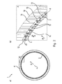
- FIG. 2a shows a cross-sectional view
- FIG. 2b a corresponding enlargement of the detail A.
- the inner tube 2 which is coated on the radial direction of the central longitudinal axis of the inner tube 2 relative to the outside of the capillary structure K. This is again particularly evident in FIG. 2b shown in an enlarged view.
- a coarse wire mesh 12 is arranged consisting of individual wires 13, which are pressed against an underside 14 directly on the outer circumferential surface 8 lying flat against this. This ensures that a sufficiently conductive heat transfer Q ⁇ between inner tube and coarse wire mesh 12 takes place.
- a distance a is formed which represents the geometric pore size named in the previous description.
- R outwardly follows on the coarse wire cloth 12 over this finer wire mesh 15, which in turn consists of individual wires, which are arranged at a distance to each other, but the wire diameter compared to the wires 13 of the coarse wire mesh 12 and the distance the distance a of the coarse wire mesh 12 are chosen to be much smaller.
- a corresponding sintered layer 16 or Sintered material can not penetrate through the mesh or pore size of the fine wire mesh and thus individual free spaces 17 or pores remain in the coarse wire mesh 12, which then allow a second medium to flow through with a turbulent flow.
Landscapes
- Engineering & Computer Science (AREA)
- Mechanical Engineering (AREA)
- General Engineering & Computer Science (AREA)
- Chemical & Material Sciences (AREA)
- Physics & Mathematics (AREA)
- Thermal Sciences (AREA)
- Combustion & Propulsion (AREA)
- Manufacturing & Machinery (AREA)
- Life Sciences & Earth Sciences (AREA)
- Sustainable Development (AREA)
- Materials Engineering (AREA)
- Sustainable Energy (AREA)
- Composite Materials (AREA)
- Geometry (AREA)
- Dispersion Chemistry (AREA)
- Metallurgy (AREA)
- Organic Chemistry (AREA)
- Vaporization, Distillation, Condensation, Sublimation, And Cold Traps (AREA)
- Powder Metallurgy (AREA)
Claims (11)
- Tube d'évaporateur (1) à aménager dans un boyau de gaz d'échappement d'un véhicule automobile, dans lequel un tube interne (2) pour acheminer un premier agent calorifique est agencé dans le tube d'évaporateur (1) et le tube interne (2) est entouré sur sa surface de chemisage externe (8) par un canal d'évaporation (9), dans lequel on peut acheminer un second agent à travers le canal d'évaporation, caractérisé en ce que, dans le canal d'évaporation (9), est aménagé dans la direction radiale (R) vers l'extérieur sur la surface de chemisage externe (8) du tube interne (2) un grillage grossier (12) suivi d'un grillage (15) plus fin par rapport à celui-cien y intercalant éventuellement une couche intermédiaire et une couche frittée (16), elles-mêmes suivies d'un grillage fin éventuel (18) et d'un tube formant boîtier (3).
- Tube d'évaporateur selon la revendication1, caractérisé en ce que le tube interne (2), les grillages (12, 15, 18), la couche frittée (16) et le tube formant boîtier (3) sont constitués du même matériau, en particulier d'un matériau de type acier fin.
- Tube d'évaporateur selon la revendication 1 ou la revendication 2, caractérisé en ce que le grillage grossier (12) présente une épaisseur de couche de 0,5 mm à 2 mm, en particulier de 0,8 mm à 1,2 mm, et une grosseur de pores entre 0,1 mm et 0,5 mm, de préférence de 0,2 mm à 0,4 mm.
- Tube d'évaporateur selon l'une quelconque des revendications 1 à 3, caractérisé en ce que le grillage grossier (12) est comprimé avec la surface de chemisage externe (8) de sorte que 40 à 60 %, de préférence 45 à 55 % de la surface de chemisage externe (8) du tube interne (2) soient en contact d'appui avec le grillage grossier (12).
- Tube d'évaporateur selon l'une quelconque des revendications 1 à 4, caractérisé en ce que les grillages fins (15, 18) présentent une épaisseur de couche de 0,05 mm à 0,3 mm, en particulier de 0,1 mm à 0,2 mm, et une grosseur de pores de 20 µm à 40 µm, en particulier de 25 µm à 35 µm.
- Tube d'évaporateur selon l'une quelconque des revendications 1 à 5, caractérisé en ce que la couche frittée (16) présente une porosité entre 40 et 80 %, en particulier entre 50 et 70 %, dans lequel on utilise de préférence une poudre métallique, en particulier une poudre d'acier fin ayant un calibre particulaire entre 5 à 100 µm pour la fabrication de la couche frittée.
- Tube d'évaporateur selon l'une quelconque des revendications 1 à 6, caractérisé en ce que des raccords sont prévus pour coupler le canal d'évaporation (9), lesquels raccords sont brasés avec le tube d'évaporateur (1).
- Procédé de fabrication d'un tube d'évaporateur (1) selon au moins la revendication 1, caractérisé par les étapes suivantes consistant à :• préparer un tube interne (2),• appliquer le grillage grossier (12) sur le grillage fin(15) en intercalant éventuellement une couche intermédiaire,• appliquer les grillages (12, 15) sur la surface de chemisage externe (8) du tube interne (2),• préparer une chemise annulaire constituée de grillage fin (18) et aménager le tube interne (2) dans la chemise annulaire et/ou un tube formant boîtier (3),• remplir l'intervalle annulaire obtenu par un matériau de frittage et• fritter l'ensemble.
- Procédé selon la revendication 8, caractérisé en ce que le grillage grossier (12) est couplé d'un seul tenant avec la surface de chemisage externe (8), en particulier par un procédé de jonction thermique.
- Procédé selon la revendication 8 ou la revendication 9, caractérisé en ce que des raccords sont couplés simultanément lors du procédé de frittage avec le tube d'évaporateur (1) par brasage.
- Procédé selon l'une quelconque des revendications 8 à 10, caractérisé en ce que le grillage grossier (12) est comprimé avec le grillage fin (15) en intercalant éventuellement une couche intermédiaire.
Applications Claiming Priority (1)
| Application Number | Priority Date | Filing Date | Title |
|---|---|---|---|
| DE102013103840.9A DE102013103840A1 (de) | 2013-04-16 | 2013-04-16 | Verdampferrohr zur Anordnung in einem Abgasstrang sowie Verfahren zur Herstellung des Verdampferrohres mit poröser Sinterstruktur und Dampfkanälen |
Publications (2)
| Publication Number | Publication Date |
|---|---|
| EP2799805A1 EP2799805A1 (fr) | 2014-11-05 |
| EP2799805B1 true EP2799805B1 (fr) | 2015-10-21 |
Family
ID=50479086
Family Applications (1)
| Application Number | Title | Priority Date | Filing Date |
|---|---|---|---|
| EP14164768.5A Not-in-force EP2799805B1 (fr) | 2013-04-16 | 2014-04-15 | Tube d'évaporateur à disposer dans un système d'échappement et procédé de fabrication du tube d'évaporateur doté d'une structure frittée poreuse et de canaux de vapeur |
Country Status (2)
| Country | Link |
|---|---|
| EP (1) | EP2799805B1 (fr) |
| DE (1) | DE102013103840A1 (fr) |
Cited By (2)
| Publication number | Priority date | Publication date | Assignee | Title |
|---|---|---|---|---|
| CN106152845A (zh) * | 2015-05-12 | 2016-11-23 | 本特勒尔汽车技术有限公司 | 机动车热传递系统 |
| US20180142967A1 (en) * | 2016-11-18 | 2018-05-24 | Ngk Insulators, Ltd. | Heat exchanger |
Families Citing this family (8)
| Publication number | Priority date | Publication date | Assignee | Title |
|---|---|---|---|---|
| DE102014223250A1 (de) * | 2014-11-14 | 2016-05-19 | Vaillant Gmbh | Verdampfer-Wärmetauscher |
| DE102014224137A1 (de) * | 2014-11-26 | 2016-06-02 | Vaillant Gmbh | Verdampfer |
| DE102015107472B3 (de) * | 2015-05-12 | 2016-08-04 | Benteler Automobiltechnik Gmbh | Kraftfahrzeug-Wärmeübertragersystem |
| DE102015213320A1 (de) * | 2015-07-16 | 2017-01-19 | Vaillant Gmbh | Wärmetauscher für einen Verdampfer |
| DE102016209082A1 (de) | 2016-05-25 | 2017-11-30 | Fraunhofer-Gesellschaft zur Förderung der angewandten Forschung e.V. | Verdampfer- und/oder Kondensatorelement mit oberflächlich eingebetteten porösen Partikeln |
| CN113566622A (zh) * | 2020-09-18 | 2021-10-29 | 昆山同川铜业科技有限公司 | 一种丝网毛细吸液芯及含该丝网毛细吸液芯的芯片散热器 |
| CN113566624B (zh) * | 2020-09-22 | 2026-01-20 | 昆山同川铜业科技有限公司 | 毛细吸液芯及其制备方法、以及芯片散热器 |
| CN115823921B (zh) * | 2022-12-20 | 2026-02-06 | 苏州远桥精密电子有限公司 | 复合超薄热管及其生产工艺 |
Family Cites Families (7)
| Publication number | Priority date | Publication date | Assignee | Title |
|---|---|---|---|---|
| DE2243428A1 (de) * | 1972-09-04 | 1974-03-14 | Bosch Gmbh Robert | Anlage zur abgasentgiftung von brennkraftmaschinen |
| TWI289651B (en) * | 2005-03-25 | 2007-11-11 | Foxconn Tech Co Ltd | Method for making wick structure of heat pipe |
| US20060260786A1 (en) * | 2005-05-23 | 2006-11-23 | Faffe Limited | Composite wick structure of heat pipe |
| US20070228116A1 (en) * | 2006-03-31 | 2007-10-04 | Jaffe Limited | Method for adhering a heat pipe wall and a wick structure |
| KR100982957B1 (ko) | 2008-06-23 | 2010-09-17 | 성균관대학교산학협력단 | 루프 히트파이프 시스템용 증발기의 제조방법 |
| US20100319895A1 (en) * | 2009-06-19 | 2010-12-23 | Wei-En Chen | Heat spreader structure and method of manufacturing the same |
| DE102011103110B4 (de) * | 2011-05-25 | 2014-08-28 | Benteler Automobiltechnik Gmbh | Abgassystem mit Kreislaufwärmerohr |
-
2013
- 2013-04-16 DE DE102013103840.9A patent/DE102013103840A1/de not_active Withdrawn
-
2014
- 2014-04-15 EP EP14164768.5A patent/EP2799805B1/fr not_active Not-in-force
Cited By (4)
| Publication number | Priority date | Publication date | Assignee | Title |
|---|---|---|---|---|
| CN106152845A (zh) * | 2015-05-12 | 2016-11-23 | 本特勒尔汽车技术有限公司 | 机动车热传递系统 |
| CN106152845B (zh) * | 2015-05-12 | 2019-04-19 | 本特勒尔汽车技术有限公司 | 机动车热传递系统 |
| US20180142967A1 (en) * | 2016-11-18 | 2018-05-24 | Ngk Insulators, Ltd. | Heat exchanger |
| US10619947B2 (en) * | 2016-11-18 | 2020-04-14 | Ngk Insulators, Ltd. | Heat exchanger |
Also Published As
| Publication number | Publication date |
|---|---|
| EP2799805A1 (fr) | 2014-11-05 |
| DE102013103840A1 (de) | 2014-10-16 |
Similar Documents
| Publication | Publication Date | Title |
|---|---|---|
| EP2799805B1 (fr) | Tube d'évaporateur à disposer dans un système d'échappement et procédé de fabrication du tube d'évaporateur doté d'une structure frittée poreuse et de canaux de vapeur | |
| EP3711462B1 (fr) | Procédé pour joindre deux composants | |
| EP3685025B1 (fr) | Plaque chauffante pour être chauffée électriquement pour post-traitement de gaz d'échappement | |
| DE102020107240A1 (de) | Kompositverbindung zweier Bauteile | |
| DE102009000751A1 (de) | Glührohr für eine Glühstiftkerze und Verfahren zu dessen Herstellung | |
| EP1926893A1 (fr) | Corps alveolaire comprenant une zone de soudure forte cote frontal | |
| EP2755249B1 (fr) | Capteur piézoélectrique et procédé de fabrication d'un dispositif piézoélectrique | |
| EP2792437B1 (fr) | Procédé de fabrication d'un tube d'évaporateur | |
| EP2348251B1 (fr) | Dispositif de chauffage d'un liquide et procédé de fabrication d'un dispositif de chauffage pour le chauffage d'un liquide | |
| AT523430B1 (de) | Verfahren zur Herstellung eines Wärmerohres | |
| DE102015001880A1 (de) | Verfahren und Vorrichtung zur Herstellung einer Kunststoffmatte mit Verstärkung am Kapillarrohr | |
| EP2950031B1 (fr) | Échangeur thermique de gaz d'échappement en acier duplex | |
| DE102011015219A1 (de) | Verlötbare Elektrode und Verfahren zur Herstellung einer verlötbaren Elektrode | |
| EP2527761A2 (fr) | Dispositif de transfert thermique | |
| WO2020038962A1 (fr) | Catalyseur | |
| DE102014002643B4 (de) | Hülse sowie Verfahren zur Herstellung einer Verbindung | |
| DE102019128727A1 (de) | Verfahren zur Herstellung eines Entschäumers | |
| DE102016109369B4 (de) | Brennstoffverdampferbaugruppe, brennstoffbetriebenes Heizgerät und Verfahren zur Herstellung einer Brennstoffverdampferbaugruppe | |
| EP3542117A1 (fr) | Échangeur de chaleur et procédé de fabrication correspondant | |
| DE102016203017B3 (de) | Verfahren zur Herstellung eines Katalysators | |
| DE102017216630B4 (de) | Verfahren zur Herstellung eines Wärmeübertragers | |
| EP1945924A1 (fr) | Corps en nid d'abeilles pour une unite de traitement des gaz d'echappement | |
| DE102024102713A1 (de) | Verfahren zum Befestigen eines Drahts an einem Anschlusselement | |
| EP3992510A1 (fr) | Ensemble de raccordement de fluide | |
| WO2014082769A1 (fr) | Moyen de liaison, pour la liaison d'au moins deux composants en utilisant un processus de frittage |
Legal Events
| Date | Code | Title | Description |
|---|---|---|---|
| PUAI | Public reference made under article 153(3) epc to a published international application that has entered the european phase |
Free format text: ORIGINAL CODE: 0009012 |
|
| 17P | Request for examination filed |
Effective date: 20140415 |
|
| AK | Designated contracting states |
Kind code of ref document: A1 Designated state(s): AL AT BE BG CH CY CZ DE DK EE ES FI FR GB GR HR HU IE IS IT LI LT LU LV MC MK MT NL NO PL PT RO RS SE SI SK SM TR |
|
| AX | Request for extension of the european patent |
Extension state: BA ME |
|
| R17P | Request for examination filed (corrected) |
Effective date: 20141127 |
|
| GRAP | Despatch of communication of intention to grant a patent |
Free format text: ORIGINAL CODE: EPIDOSNIGR1 |
|
| INTG | Intention to grant announced |
Effective date: 20150611 |
|
| GRAS | Grant fee paid |
Free format text: ORIGINAL CODE: EPIDOSNIGR3 |
|
| GRAA | (expected) grant |
Free format text: ORIGINAL CODE: 0009210 |
|
| RIN1 | Information on inventor provided before grant (corrected) |
Inventor name: DUEPMEIER, TOBIAS Inventor name: REUL, BENJAMIN Inventor name: GREWE, DIMITRA Inventor name: RUBITSCHEK, FELIX |
|
| AK | Designated contracting states |
Kind code of ref document: B1 Designated state(s): AL AT BE BG CH CY CZ DE DK EE ES FI FR GB GR HR HU IE IS IT LI LT LU LV MC MK MT NL NO PL PT RO RS SE SI SK SM TR |
|
| REG | Reference to a national code |
Ref country code: GB Ref legal event code: FG4D Free format text: NOT ENGLISH Ref country code: NL Ref legal event code: MP Effective date: 20151021 |
|
| REG | Reference to a national code |
Ref country code: CH Ref legal event code: EP |
|
| REG | Reference to a national code |
Ref country code: AT Ref legal event code: REF Ref document number: 756870 Country of ref document: AT Kind code of ref document: T Effective date: 20151115 |
|
| REG | Reference to a national code |
Ref country code: IE Ref legal event code: FG4D Free format text: LANGUAGE OF EP DOCUMENT: GERMAN |
|
| REG | Reference to a national code |
Ref country code: DE Ref legal event code: R096 Ref document number: 502014000156 Country of ref document: DE |
|
| REG | Reference to a national code |
Ref country code: LT Ref legal event code: MG4D |
|
| REG | Reference to a national code |
Ref country code: FR Ref legal event code: PLFP Year of fee payment: 3 |
|
| PG25 | Lapsed in a contracting state [announced via postgrant information from national office to epo] |
Ref country code: HR Free format text: LAPSE BECAUSE OF FAILURE TO SUBMIT A TRANSLATION OF THE DESCRIPTION OR TO PAY THE FEE WITHIN THE PRESCRIBED TIME-LIMIT Effective date: 20151021 Ref country code: IT Free format text: LAPSE BECAUSE OF FAILURE TO SUBMIT A TRANSLATION OF THE DESCRIPTION OR TO PAY THE FEE WITHIN THE PRESCRIBED TIME-LIMIT Effective date: 20151021 Ref country code: NO Free format text: LAPSE BECAUSE OF FAILURE TO SUBMIT A TRANSLATION OF THE DESCRIPTION OR TO PAY THE FEE WITHIN THE PRESCRIBED TIME-LIMIT Effective date: 20160121 Ref country code: ES Free format text: LAPSE BECAUSE OF FAILURE TO SUBMIT A TRANSLATION OF THE DESCRIPTION OR TO PAY THE FEE WITHIN THE PRESCRIBED TIME-LIMIT Effective date: 20151021 Ref country code: LT Free format text: LAPSE BECAUSE OF FAILURE TO SUBMIT A TRANSLATION OF THE DESCRIPTION OR TO PAY THE FEE WITHIN THE PRESCRIBED TIME-LIMIT Effective date: 20151021 Ref country code: NL Free format text: LAPSE BECAUSE OF FAILURE TO SUBMIT A TRANSLATION OF THE DESCRIPTION OR TO PAY THE FEE WITHIN THE PRESCRIBED TIME-LIMIT Effective date: 20151021 Ref country code: IS Free format text: LAPSE BECAUSE OF FAILURE TO SUBMIT A TRANSLATION OF THE DESCRIPTION OR TO PAY THE FEE WITHIN THE PRESCRIBED TIME-LIMIT Effective date: 20160221 |
|
| PG25 | Lapsed in a contracting state [announced via postgrant information from national office to epo] |
Ref country code: SE Free format text: LAPSE BECAUSE OF FAILURE TO SUBMIT A TRANSLATION OF THE DESCRIPTION OR TO PAY THE FEE WITHIN THE PRESCRIBED TIME-LIMIT Effective date: 20151021 Ref country code: PT Free format text: LAPSE BECAUSE OF FAILURE TO SUBMIT A TRANSLATION OF THE DESCRIPTION OR TO PAY THE FEE WITHIN THE PRESCRIBED TIME-LIMIT Effective date: 20160222 Ref country code: GR Free format text: LAPSE BECAUSE OF FAILURE TO SUBMIT A TRANSLATION OF THE DESCRIPTION OR TO PAY THE FEE WITHIN THE PRESCRIBED TIME-LIMIT Effective date: 20160122 Ref country code: LV Free format text: LAPSE BECAUSE OF FAILURE TO SUBMIT A TRANSLATION OF THE DESCRIPTION OR TO PAY THE FEE WITHIN THE PRESCRIBED TIME-LIMIT Effective date: 20151021 Ref country code: FI Free format text: LAPSE BECAUSE OF FAILURE TO SUBMIT A TRANSLATION OF THE DESCRIPTION OR TO PAY THE FEE WITHIN THE PRESCRIBED TIME-LIMIT Effective date: 20151021 Ref country code: PL Free format text: LAPSE BECAUSE OF FAILURE TO SUBMIT A TRANSLATION OF THE DESCRIPTION OR TO PAY THE FEE WITHIN THE PRESCRIBED TIME-LIMIT Effective date: 20151021 Ref country code: RS Free format text: LAPSE BECAUSE OF FAILURE TO SUBMIT A TRANSLATION OF THE DESCRIPTION OR TO PAY THE FEE WITHIN THE PRESCRIBED TIME-LIMIT Effective date: 20151021 |
|
| REG | Reference to a national code |
Ref country code: DE Ref legal event code: R097 Ref document number: 502014000156 Country of ref document: DE |
|
| PG25 | Lapsed in a contracting state [announced via postgrant information from national office to epo] |
Ref country code: CZ Free format text: LAPSE BECAUSE OF FAILURE TO SUBMIT A TRANSLATION OF THE DESCRIPTION OR TO PAY THE FEE WITHIN THE PRESCRIBED TIME-LIMIT Effective date: 20151021 |
|
| PLBE | No opposition filed within time limit |
Free format text: ORIGINAL CODE: 0009261 |
|
| STAA | Information on the status of an ep patent application or granted ep patent |
Free format text: STATUS: NO OPPOSITION FILED WITHIN TIME LIMIT |
|
| PG25 | Lapsed in a contracting state [announced via postgrant information from national office to epo] |
Ref country code: SK Free format text: LAPSE BECAUSE OF FAILURE TO SUBMIT A TRANSLATION OF THE DESCRIPTION OR TO PAY THE FEE WITHIN THE PRESCRIBED TIME-LIMIT Effective date: 20151021 Ref country code: RO Free format text: LAPSE BECAUSE OF FAILURE TO SUBMIT A TRANSLATION OF THE DESCRIPTION OR TO PAY THE FEE WITHIN THE PRESCRIBED TIME-LIMIT Effective date: 20151021 Ref country code: BE Free format text: LAPSE BECAUSE OF NON-PAYMENT OF DUE FEES Effective date: 20160430 Ref country code: EE Free format text: LAPSE BECAUSE OF FAILURE TO SUBMIT A TRANSLATION OF THE DESCRIPTION OR TO PAY THE FEE WITHIN THE PRESCRIBED TIME-LIMIT Effective date: 20151021 Ref country code: SM Free format text: LAPSE BECAUSE OF FAILURE TO SUBMIT A TRANSLATION OF THE DESCRIPTION OR TO PAY THE FEE WITHIN THE PRESCRIBED TIME-LIMIT Effective date: 20151021 Ref country code: DK Free format text: LAPSE BECAUSE OF FAILURE TO SUBMIT A TRANSLATION OF THE DESCRIPTION OR TO PAY THE FEE WITHIN THE PRESCRIBED TIME-LIMIT Effective date: 20151021 |
|
| 26N | No opposition filed |
Effective date: 20160722 |
|
| PG25 | Lapsed in a contracting state [announced via postgrant information from national office to epo] |
Ref country code: SI Free format text: LAPSE BECAUSE OF FAILURE TO SUBMIT A TRANSLATION OF THE DESCRIPTION OR TO PAY THE FEE WITHIN THE PRESCRIBED TIME-LIMIT Effective date: 20151021 |
|
| PG25 | Lapsed in a contracting state [announced via postgrant information from national office to epo] |
Ref country code: LU Free format text: LAPSE BECAUSE OF FAILURE TO SUBMIT A TRANSLATION OF THE DESCRIPTION OR TO PAY THE FEE WITHIN THE PRESCRIBED TIME-LIMIT Effective date: 20160415 |
|
| REG | Reference to a national code |
Ref country code: IE Ref legal event code: MM4A |
|
| REG | Reference to a national code |
Ref country code: FR Ref legal event code: PLFP Year of fee payment: 4 |
|
| PG25 | Lapsed in a contracting state [announced via postgrant information from national office to epo] |
Ref country code: IE Free format text: LAPSE BECAUSE OF NON-PAYMENT OF DUE FEES Effective date: 20160415 |
|
| REG | Reference to a national code |
Ref country code: CH Ref legal event code: PL |
|
| PG25 | Lapsed in a contracting state [announced via postgrant information from national office to epo] |
Ref country code: CH Free format text: LAPSE BECAUSE OF NON-PAYMENT OF DUE FEES Effective date: 20170430 Ref country code: LI Free format text: LAPSE BECAUSE OF NON-PAYMENT OF DUE FEES Effective date: 20170430 |
|
| REG | Reference to a national code |
Ref country code: FR Ref legal event code: PLFP Year of fee payment: 5 |
|
| PG25 | Lapsed in a contracting state [announced via postgrant information from national office to epo] |
Ref country code: HU Free format text: LAPSE BECAUSE OF FAILURE TO SUBMIT A TRANSLATION OF THE DESCRIPTION OR TO PAY THE FEE WITHIN THE PRESCRIBED TIME-LIMIT; INVALID AB INITIO Effective date: 20140415 |
|
| PG25 | Lapsed in a contracting state [announced via postgrant information from national office to epo] |
Ref country code: CY Free format text: LAPSE BECAUSE OF FAILURE TO SUBMIT A TRANSLATION OF THE DESCRIPTION OR TO PAY THE FEE WITHIN THE PRESCRIBED TIME-LIMIT Effective date: 20151021 Ref country code: MC Free format text: LAPSE BECAUSE OF FAILURE TO SUBMIT A TRANSLATION OF THE DESCRIPTION OR TO PAY THE FEE WITHIN THE PRESCRIBED TIME-LIMIT Effective date: 20151021 Ref country code: MT Free format text: LAPSE BECAUSE OF FAILURE TO SUBMIT A TRANSLATION OF THE DESCRIPTION OR TO PAY THE FEE WITHIN THE PRESCRIBED TIME-LIMIT Effective date: 20151021 Ref country code: MK Free format text: LAPSE BECAUSE OF FAILURE TO SUBMIT A TRANSLATION OF THE DESCRIPTION OR TO PAY THE FEE WITHIN THE PRESCRIBED TIME-LIMIT Effective date: 20151021 |
|
| PG25 | Lapsed in a contracting state [announced via postgrant information from national office to epo] |
Ref country code: BG Free format text: LAPSE BECAUSE OF FAILURE TO SUBMIT A TRANSLATION OF THE DESCRIPTION OR TO PAY THE FEE WITHIN THE PRESCRIBED TIME-LIMIT Effective date: 20151021 |
|
| PGFP | Annual fee paid to national office [announced via postgrant information from national office to epo] |
Ref country code: DE Payment date: 20180427 Year of fee payment: 5 |
|
| PGFP | Annual fee paid to national office [announced via postgrant information from national office to epo] |
Ref country code: FR Payment date: 20180420 Year of fee payment: 5 |
|
| PG25 | Lapsed in a contracting state [announced via postgrant information from national office to epo] |
Ref country code: AL Free format text: LAPSE BECAUSE OF FAILURE TO SUBMIT A TRANSLATION OF THE DESCRIPTION OR TO PAY THE FEE WITHIN THE PRESCRIBED TIME-LIMIT Effective date: 20151021 Ref country code: TR Free format text: LAPSE BECAUSE OF FAILURE TO SUBMIT A TRANSLATION OF THE DESCRIPTION OR TO PAY THE FEE WITHIN THE PRESCRIBED TIME-LIMIT Effective date: 20151021 |
|
| PGFP | Annual fee paid to national office [announced via postgrant information from national office to epo] |
Ref country code: GB Payment date: 20180418 Year of fee payment: 5 |
|
| REG | Reference to a national code |
Ref country code: DE Ref legal event code: R119 Ref document number: 502014000156 Country of ref document: DE |
|
| GBPC | Gb: european patent ceased through non-payment of renewal fee |
Effective date: 20190415 |
|
| PG25 | Lapsed in a contracting state [announced via postgrant information from national office to epo] |
Ref country code: GB Free format text: LAPSE BECAUSE OF NON-PAYMENT OF DUE FEES Effective date: 20190415 Ref country code: DE Free format text: LAPSE BECAUSE OF NON-PAYMENT OF DUE FEES Effective date: 20191101 |
|
| PG25 | Lapsed in a contracting state [announced via postgrant information from national office to epo] |
Ref country code: FR Free format text: LAPSE BECAUSE OF NON-PAYMENT OF DUE FEES Effective date: 20190430 |
|
| REG | Reference to a national code |
Ref country code: AT Ref legal event code: MM01 Ref document number: 756870 Country of ref document: AT Kind code of ref document: T Effective date: 20190415 |
|
| PG25 | Lapsed in a contracting state [announced via postgrant information from national office to epo] |
Ref country code: AT Free format text: LAPSE BECAUSE OF NON-PAYMENT OF DUE FEES Effective date: 20190415 |