EP2800169B1 - Batteriezellenanordnung mit erhöhter sicherheit und batteriemodul damit - Google Patents
Batteriezellenanordnung mit erhöhter sicherheit und batteriemodul damit Download PDFInfo
- Publication number
- EP2800169B1 EP2800169B1 EP13755553.8A EP13755553A EP2800169B1 EP 2800169 B1 EP2800169 B1 EP 2800169B1 EP 13755553 A EP13755553 A EP 13755553A EP 2800169 B1 EP2800169 B1 EP 2800169B1
- Authority
- EP
- European Patent Office
- Prior art keywords
- battery
- battery cells
- expansion opening
- opening parts
- cell assembly
- Prior art date
- Legal status (The legal status is an assumption and is not a legal conclusion. Google has not performed a legal analysis and makes no representation as to the accuracy of the status listed.)
- Active
Links
Images


Classifications
-
- H—ELECTRICITY
- H01—ELECTRIC ELEMENTS
- H01M—PROCESSES OR MEANS, e.g. BATTERIES, FOR THE DIRECT CONVERSION OF CHEMICAL ENERGY INTO ELECTRICAL ENERGY
- H01M50/00—Constructional details or processes of manufacture of the non-active parts of electrochemical cells other than fuel cells, e.g. hybrid cells
- H01M50/50—Current conducting connections for cells or batteries
- H01M50/572—Means for preventing undesired use or discharge
- H01M50/574—Devices or arrangements for the interruption of current
- H01M50/578—Devices or arrangements for the interruption of current in response to pressure
-
- H—ELECTRICITY
- H01—ELECTRIC ELEMENTS
- H01M—PROCESSES OR MEANS, e.g. BATTERIES, FOR THE DIRECT CONVERSION OF CHEMICAL ENERGY INTO ELECTRICAL ENERGY
- H01M50/00—Constructional details or processes of manufacture of the non-active parts of electrochemical cells other than fuel cells, e.g. hybrid cells
- H01M50/50—Current conducting connections for cells or batteries
- H01M50/528—Fixed electrical connections, i.e. not intended for disconnection
-
- B—PERFORMING OPERATIONS; TRANSPORTING
- B60—VEHICLES IN GENERAL
- B60L—PROPULSION OF ELECTRICALLY-PROPELLED VEHICLES; SUPPLYING ELECTRIC POWER FOR AUXILIARY EQUIPMENT OF ELECTRICALLY-PROPELLED VEHICLES; ELECTRODYNAMIC BRAKE SYSTEMS FOR VEHICLES IN GENERAL; MAGNETIC SUSPENSION OR LEVITATION FOR VEHICLES; MONITORING OPERATING VARIABLES OF ELECTRICALLY-PROPELLED VEHICLES; ELECTRIC SAFETY DEVICES FOR ELECTRICALLY-PROPELLED VEHICLES
- B60L3/00—Electric devices on electrically-propelled vehicles for safety purposes; Monitoring operating variables, e.g. speed, deceleration or energy consumption
- B60L3/0023—Detecting, eliminating, remedying or compensating for drive train abnormalities, e.g. failures within the drive train
- B60L3/0046—Detecting, eliminating, remedying or compensating for drive train abnormalities, e.g. failures within the drive train relating to electric energy storage systems, e.g. batteries or capacitors
-
- B—PERFORMING OPERATIONS; TRANSPORTING
- B60—VEHICLES IN GENERAL
- B60L—PROPULSION OF ELECTRICALLY-PROPELLED VEHICLES; SUPPLYING ELECTRIC POWER FOR AUXILIARY EQUIPMENT OF ELECTRICALLY-PROPELLED VEHICLES; ELECTRODYNAMIC BRAKE SYSTEMS FOR VEHICLES IN GENERAL; MAGNETIC SUSPENSION OR LEVITATION FOR VEHICLES; MONITORING OPERATING VARIABLES OF ELECTRICALLY-PROPELLED VEHICLES; ELECTRIC SAFETY DEVICES FOR ELECTRICALLY-PROPELLED VEHICLES
- B60L3/00—Electric devices on electrically-propelled vehicles for safety purposes; Monitoring operating variables, e.g. speed, deceleration or energy consumption
- B60L3/12—Recording operating variables ; Monitoring of operating variables
-
- B—PERFORMING OPERATIONS; TRANSPORTING
- B60—VEHICLES IN GENERAL
- B60L—PROPULSION OF ELECTRICALLY-PROPELLED VEHICLES; SUPPLYING ELECTRIC POWER FOR AUXILIARY EQUIPMENT OF ELECTRICALLY-PROPELLED VEHICLES; ELECTRODYNAMIC BRAKE SYSTEMS FOR VEHICLES IN GENERAL; MAGNETIC SUSPENSION OR LEVITATION FOR VEHICLES; MONITORING OPERATING VARIABLES OF ELECTRICALLY-PROPELLED VEHICLES; ELECTRIC SAFETY DEVICES FOR ELECTRICALLY-PROPELLED VEHICLES
- B60L50/00—Electric propulsion with power supplied within the vehicle
- B60L50/50—Electric propulsion with power supplied within the vehicle using propulsion power supplied by batteries or fuel cells
- B60L50/60—Electric propulsion with power supplied within the vehicle using propulsion power supplied by batteries or fuel cells using power supplied by batteries
- B60L50/64—Constructional details of batteries specially adapted for electric vehicles
-
- B—PERFORMING OPERATIONS; TRANSPORTING
- B60—VEHICLES IN GENERAL
- B60L—PROPULSION OF ELECTRICALLY-PROPELLED VEHICLES; SUPPLYING ELECTRIC POWER FOR AUXILIARY EQUIPMENT OF ELECTRICALLY-PROPELLED VEHICLES; ELECTRODYNAMIC BRAKE SYSTEMS FOR VEHICLES IN GENERAL; MAGNETIC SUSPENSION OR LEVITATION FOR VEHICLES; MONITORING OPERATING VARIABLES OF ELECTRICALLY-PROPELLED VEHICLES; ELECTRIC SAFETY DEVICES FOR ELECTRICALLY-PROPELLED VEHICLES
- B60L58/00—Methods or circuit arrangements for monitoring or controlling batteries or fuel cells, specially adapted for electric vehicles
- B60L58/10—Methods or circuit arrangements for monitoring or controlling batteries or fuel cells, specially adapted for electric vehicles for monitoring or controlling batteries
- B60L58/12—Methods or circuit arrangements for monitoring or controlling batteries or fuel cells, specially adapted for electric vehicles for monitoring or controlling batteries responding to state of charge [SoC]
- B60L58/14—Preventing excessive discharging
-
- B—PERFORMING OPERATIONS; TRANSPORTING
- B60—VEHICLES IN GENERAL
- B60L—PROPULSION OF ELECTRICALLY-PROPELLED VEHICLES; SUPPLYING ELECTRIC POWER FOR AUXILIARY EQUIPMENT OF ELECTRICALLY-PROPELLED VEHICLES; ELECTRODYNAMIC BRAKE SYSTEMS FOR VEHICLES IN GENERAL; MAGNETIC SUSPENSION OR LEVITATION FOR VEHICLES; MONITORING OPERATING VARIABLES OF ELECTRICALLY-PROPELLED VEHICLES; ELECTRIC SAFETY DEVICES FOR ELECTRICALLY-PROPELLED VEHICLES
- B60L58/00—Methods or circuit arrangements for monitoring or controlling batteries or fuel cells, specially adapted for electric vehicles
- B60L58/10—Methods or circuit arrangements for monitoring or controlling batteries or fuel cells, specially adapted for electric vehicles for monitoring or controlling batteries
- B60L58/12—Methods or circuit arrangements for monitoring or controlling batteries or fuel cells, specially adapted for electric vehicles for monitoring or controlling batteries responding to state of charge [SoC]
- B60L58/15—Preventing overcharging
-
- B—PERFORMING OPERATIONS; TRANSPORTING
- B60—VEHICLES IN GENERAL
- B60L—PROPULSION OF ELECTRICALLY-PROPELLED VEHICLES; SUPPLYING ELECTRIC POWER FOR AUXILIARY EQUIPMENT OF ELECTRICALLY-PROPELLED VEHICLES; ELECTRODYNAMIC BRAKE SYSTEMS FOR VEHICLES IN GENERAL; MAGNETIC SUSPENSION OR LEVITATION FOR VEHICLES; MONITORING OPERATING VARIABLES OF ELECTRICALLY-PROPELLED VEHICLES; ELECTRIC SAFETY DEVICES FOR ELECTRICALLY-PROPELLED VEHICLES
- B60L58/00—Methods or circuit arrangements for monitoring or controlling batteries or fuel cells, specially adapted for electric vehicles
- B60L58/10—Methods or circuit arrangements for monitoring or controlling batteries or fuel cells, specially adapted for electric vehicles for monitoring or controlling batteries
- B60L58/18—Methods or circuit arrangements for monitoring or controlling batteries or fuel cells, specially adapted for electric vehicles for monitoring or controlling batteries of two or more battery modules
-
- B—PERFORMING OPERATIONS; TRANSPORTING
- B60—VEHICLES IN GENERAL
- B60L—PROPULSION OF ELECTRICALLY-PROPELLED VEHICLES; SUPPLYING ELECTRIC POWER FOR AUXILIARY EQUIPMENT OF ELECTRICALLY-PROPELLED VEHICLES; ELECTRODYNAMIC BRAKE SYSTEMS FOR VEHICLES IN GENERAL; MAGNETIC SUSPENSION OR LEVITATION FOR VEHICLES; MONITORING OPERATING VARIABLES OF ELECTRICALLY-PROPELLED VEHICLES; ELECTRIC SAFETY DEVICES FOR ELECTRICALLY-PROPELLED VEHICLES
- B60L58/00—Methods or circuit arrangements for monitoring or controlling batteries or fuel cells, specially adapted for electric vehicles
- B60L58/10—Methods or circuit arrangements for monitoring or controlling batteries or fuel cells, specially adapted for electric vehicles for monitoring or controlling batteries
- B60L58/18—Methods or circuit arrangements for monitoring or controlling batteries or fuel cells, specially adapted for electric vehicles for monitoring or controlling batteries of two or more battery modules
- B60L58/21—Methods or circuit arrangements for monitoring or controlling batteries or fuel cells, specially adapted for electric vehicles for monitoring or controlling batteries of two or more battery modules having the same nominal voltage
-
- H—ELECTRICITY
- H01—ELECTRIC ELEMENTS
- H01M—PROCESSES OR MEANS, e.g. BATTERIES, FOR THE DIRECT CONVERSION OF CHEMICAL ENERGY INTO ELECTRICAL ENERGY
- H01M10/00—Secondary cells; Manufacture thereof
- H01M10/02—Details
-
- H—ELECTRICITY
- H01—ELECTRIC ELEMENTS
- H01M—PROCESSES OR MEANS, e.g. BATTERIES, FOR THE DIRECT CONVERSION OF CHEMICAL ENERGY INTO ELECTRICAL ENERGY
- H01M10/00—Secondary cells; Manufacture thereof
- H01M10/60—Heating or cooling; Temperature control
- H01M10/61—Types of temperature control
- H01M10/613—Cooling or keeping cold
-
- H—ELECTRICITY
- H01—ELECTRIC ELEMENTS
- H01M—PROCESSES OR MEANS, e.g. BATTERIES, FOR THE DIRECT CONVERSION OF CHEMICAL ENERGY INTO ELECTRICAL ENERGY
- H01M10/00—Secondary cells; Manufacture thereof
- H01M10/60—Heating or cooling; Temperature control
- H01M10/62—Heating or cooling; Temperature control specially adapted for specific applications
- H01M10/625—Vehicles
-
- H—ELECTRICITY
- H01—ELECTRIC ELEMENTS
- H01M—PROCESSES OR MEANS, e.g. BATTERIES, FOR THE DIRECT CONVERSION OF CHEMICAL ENERGY INTO ELECTRICAL ENERGY
- H01M10/00—Secondary cells; Manufacture thereof
- H01M10/60—Heating or cooling; Temperature control
- H01M10/64—Heating or cooling; Temperature control characterised by the shape of the cells
- H01M10/647—Prismatic or flat cells, e.g. pouch cells
-
- H—ELECTRICITY
- H01—ELECTRIC ELEMENTS
- H01M—PROCESSES OR MEANS, e.g. BATTERIES, FOR THE DIRECT CONVERSION OF CHEMICAL ENERGY INTO ELECTRICAL ENERGY
- H01M10/00—Secondary cells; Manufacture thereof
- H01M10/60—Heating or cooling; Temperature control
- H01M10/65—Means for temperature control structurally associated with the cells
- H01M10/655—Solid structures for heat exchange or heat conduction
- H01M10/6551—Surfaces specially adapted for heat dissipation or radiation, e.g. fins or coatings
-
- H—ELECTRICITY
- H01—ELECTRIC ELEMENTS
- H01M—PROCESSES OR MEANS, e.g. BATTERIES, FOR THE DIRECT CONVERSION OF CHEMICAL ENERGY INTO ELECTRICAL ENERGY
- H01M50/00—Constructional details or processes of manufacture of the non-active parts of electrochemical cells other than fuel cells, e.g. hybrid cells
- H01M50/10—Primary casings; Jackets or wrappings
- H01M50/102—Primary casings; Jackets or wrappings characterised by their shape or physical structure
- H01M50/105—Pouches or flexible bags
-
- H—ELECTRICITY
- H01—ELECTRIC ELEMENTS
- H01M—PROCESSES OR MEANS, e.g. BATTERIES, FOR THE DIRECT CONVERSION OF CHEMICAL ENERGY INTO ELECTRICAL ENERGY
- H01M50/00—Constructional details or processes of manufacture of the non-active parts of electrochemical cells other than fuel cells, e.g. hybrid cells
- H01M50/20—Mountings; Secondary casings or frames; Racks, modules or packs; Suspension devices; Shock absorbers; Transport or carrying devices; Holders
- H01M50/204—Racks, modules or packs for multiple batteries or multiple cells
- H01M50/207—Racks, modules or packs for multiple batteries or multiple cells characterised by their shape
- H01M50/211—Racks, modules or packs for multiple batteries or multiple cells characterised by their shape adapted for pouch cells
-
- H—ELECTRICITY
- H01—ELECTRIC ELEMENTS
- H01M—PROCESSES OR MEANS, e.g. BATTERIES, FOR THE DIRECT CONVERSION OF CHEMICAL ENERGY INTO ELECTRICAL ENERGY
- H01M50/00—Constructional details or processes of manufacture of the non-active parts of electrochemical cells other than fuel cells, e.g. hybrid cells
- H01M50/20—Mountings; Secondary casings or frames; Racks, modules or packs; Suspension devices; Shock absorbers; Transport or carrying devices; Holders
- H01M50/244—Secondary casings; Racks; Suspension devices; Carrying devices; Holders characterised by their mounting method
-
- H—ELECTRICITY
- H01—ELECTRIC ELEMENTS
- H01M—PROCESSES OR MEANS, e.g. BATTERIES, FOR THE DIRECT CONVERSION OF CHEMICAL ENERGY INTO ELECTRICAL ENERGY
- H01M50/00—Constructional details or processes of manufacture of the non-active parts of electrochemical cells other than fuel cells, e.g. hybrid cells
- H01M50/50—Current conducting connections for cells or batteries
- H01M50/502—Interconnectors for connecting terminals of adjacent batteries; Interconnectors for connecting cells outside a battery casing
- H01M50/505—Interconnectors for connecting terminals of adjacent batteries; Interconnectors for connecting cells outside a battery casing comprising a single busbar
-
- H—ELECTRICITY
- H01—ELECTRIC ELEMENTS
- H01M—PROCESSES OR MEANS, e.g. BATTERIES, FOR THE DIRECT CONVERSION OF CHEMICAL ENERGY INTO ELECTRICAL ENERGY
- H01M50/00—Constructional details or processes of manufacture of the non-active parts of electrochemical cells other than fuel cells, e.g. hybrid cells
- H01M50/50—Current conducting connections for cells or batteries
- H01M50/502—Interconnectors for connecting terminals of adjacent batteries; Interconnectors for connecting cells outside a battery casing
- H01M50/509—Interconnectors for connecting terminals of adjacent batteries; Interconnectors for connecting cells outside a battery casing characterised by the type of connection, e.g. mixed connections
-
- B—PERFORMING OPERATIONS; TRANSPORTING
- B60—VEHICLES IN GENERAL
- B60L—PROPULSION OF ELECTRICALLY-PROPELLED VEHICLES; SUPPLYING ELECTRIC POWER FOR AUXILIARY EQUIPMENT OF ELECTRICALLY-PROPELLED VEHICLES; ELECTRODYNAMIC BRAKE SYSTEMS FOR VEHICLES IN GENERAL; MAGNETIC SUSPENSION OR LEVITATION FOR VEHICLES; MONITORING OPERATING VARIABLES OF ELECTRICALLY-PROPELLED VEHICLES; ELECTRIC SAFETY DEVICES FOR ELECTRICALLY-PROPELLED VEHICLES
- B60L2240/00—Control parameters of input or output; Target parameters
- B60L2240/40—Drive Train control parameters
- B60L2240/54—Drive Train control parameters related to batteries
- B60L2240/545—Temperature
-
- B—PERFORMING OPERATIONS; TRANSPORTING
- B60—VEHICLES IN GENERAL
- B60L—PROPULSION OF ELECTRICALLY-PROPELLED VEHICLES; SUPPLYING ELECTRIC POWER FOR AUXILIARY EQUIPMENT OF ELECTRICALLY-PROPELLED VEHICLES; ELECTRODYNAMIC BRAKE SYSTEMS FOR VEHICLES IN GENERAL; MAGNETIC SUSPENSION OR LEVITATION FOR VEHICLES; MONITORING OPERATING VARIABLES OF ELECTRICALLY-PROPELLED VEHICLES; ELECTRIC SAFETY DEVICES FOR ELECTRICALLY-PROPELLED VEHICLES
- B60L2240/00—Control parameters of input or output; Target parameters
- B60L2240/40—Drive Train control parameters
- B60L2240/54—Drive Train control parameters related to batteries
- B60L2240/547—Voltage
-
- B—PERFORMING OPERATIONS; TRANSPORTING
- B60—VEHICLES IN GENERAL
- B60L—PROPULSION OF ELECTRICALLY-PROPELLED VEHICLES; SUPPLYING ELECTRIC POWER FOR AUXILIARY EQUIPMENT OF ELECTRICALLY-PROPELLED VEHICLES; ELECTRODYNAMIC BRAKE SYSTEMS FOR VEHICLES IN GENERAL; MAGNETIC SUSPENSION OR LEVITATION FOR VEHICLES; MONITORING OPERATING VARIABLES OF ELECTRICALLY-PROPELLED VEHICLES; ELECTRIC SAFETY DEVICES FOR ELECTRICALLY-PROPELLED VEHICLES
- B60L2240/00—Control parameters of input or output; Target parameters
- B60L2240/40—Drive Train control parameters
- B60L2240/54—Drive Train control parameters related to batteries
- B60L2240/549—Current
-
- H—ELECTRICITY
- H01—ELECTRIC ELEMENTS
- H01M—PROCESSES OR MEANS, e.g. BATTERIES, FOR THE DIRECT CONVERSION OF CHEMICAL ENERGY INTO ELECTRICAL ENERGY
- H01M2200/00—Safety devices for primary or secondary batteries
- H01M2200/20—Pressure-sensitive devices
-
- H—ELECTRICITY
- H01—ELECTRIC ELEMENTS
- H01M—PROCESSES OR MEANS, e.g. BATTERIES, FOR THE DIRECT CONVERSION OF CHEMICAL ENERGY INTO ELECTRICAL ENERGY
- H01M2220/00—Batteries for particular applications
- H01M2220/20—Batteries in motive systems, e.g. vehicle, ship, plane
-
- H—ELECTRICITY
- H01—ELECTRIC ELEMENTS
- H01M—PROCESSES OR MEANS, e.g. BATTERIES, FOR THE DIRECT CONVERSION OF CHEMICAL ENERGY INTO ELECTRICAL ENERGY
- H01M2220/00—Batteries for particular applications
- H01M2220/30—Batteries in portable systems, e.g. mobile phone, laptop
-
- Y—GENERAL TAGGING OF NEW TECHNOLOGICAL DEVELOPMENTS; GENERAL TAGGING OF CROSS-SECTIONAL TECHNOLOGIES SPANNING OVER SEVERAL SECTIONS OF THE IPC; TECHNICAL SUBJECTS COVERED BY FORMER USPC CROSS-REFERENCE ART COLLECTIONS [XRACs] AND DIGESTS
- Y02—TECHNOLOGIES OR APPLICATIONS FOR MITIGATION OR ADAPTATION AGAINST CLIMATE CHANGE
- Y02E—REDUCTION OF GREENHOUSE GAS [GHG] EMISSIONS, RELATED TO ENERGY GENERATION, TRANSMISSION OR DISTRIBUTION
- Y02E60/00—Enabling technologies; Technologies with a potential or indirect contribution to GHG emissions mitigation
- Y02E60/10—Energy storage using batteries
-
- Y—GENERAL TAGGING OF NEW TECHNOLOGICAL DEVELOPMENTS; GENERAL TAGGING OF CROSS-SECTIONAL TECHNOLOGIES SPANNING OVER SEVERAL SECTIONS OF THE IPC; TECHNICAL SUBJECTS COVERED BY FORMER USPC CROSS-REFERENCE ART COLLECTIONS [XRACs] AND DIGESTS
- Y02—TECHNOLOGIES OR APPLICATIONS FOR MITIGATION OR ADAPTATION AGAINST CLIMATE CHANGE
- Y02T—CLIMATE CHANGE MITIGATION TECHNOLOGIES RELATED TO TRANSPORTATION
- Y02T10/00—Road transport of goods or passengers
- Y02T10/60—Other road transportation technologies with climate change mitigation effect
- Y02T10/70—Energy storage systems for electromobility, e.g. batteries
Definitions
- the present invention relates to a battery cell assembly with improved safety and a battery module including the same and, more particularly, to a battery cell assembly including a plurality of battery cells stacked while being electrically connected to each other, wherein one or more of the battery cells are mounted in each cell housing member in a state in which opposite sides of the battery cells are surrounded by each cell housing member excluding electrode terminals of the battery cells, an expansion opening part, through which a portion of a main body of each of the battery cells is exposed outward when the battery cells expand, is formed at one surface or opposite surfaces of each of the at least two cell housing members and the battery cells are stacked such that the at least two expansion opening parts face each other.
- a secondary battery which can be charged and discharged, has been widely used as an energy source for wireless mobile devices.
- the secondary battery has attracted considerable attention as a power source for electric vehicles (EV), hybrid electric vehicles (HEV), and plug-in hybrid electric vehicles (Plug-In HEV), which have been developed to solve problems, such as air pollution, caused by existing gasoline and diesel vehicles using fossil fuels or as a power storage device to store surplus power such that the power can be used as needed.
- EV electric vehicles
- HEV hybrid electric vehicles
- Plug-In HEV plug-in hybrid electric vehicles
- Small-sized mobile devices use one or several battery cells for each device.
- middle or large-sized devices such as vehicles, use a battery module having a plurality of battery cells electrically connected to each other because high output and large capacity are necessary for the middle or large-sized devices.
- the battery module is manufactured so as to have as small a size and weight as possible.
- a prismatic battery or a pouch-shaped battery which can be stacked with high integration and has a small weight to capacity ratio, is usually used as a battery cell of the middle or large-sized battery module.
- much interest is currently focused on such a pouch-shaped battery, which uses an aluminum laminate sheet as a sheathing member, because the pouch-shaped battery is lightweight and the manufacturing cost of the pouch-shaped battery is low.
- the battery module is configured to have a structure in which a plurality of battery cells is combined.
- a large amount of gas is generated due to decomposition of an electrolyte with the result that a battery case of each of the battery cells swells, i.e. a so-called swelling phenomenon occurs.
- the swelling phenomenon further accelerates decomposition of the electrolyte while causing high pressure in the sealed battery case with the result that the battery module may explode.
- abnormal operation of some of the battery cells may cause abnormal operation of the other battery cells with the result that a fire or explosion of the battery module may occur, which may lead to a large-scale accident.
- the secondary battery is provided with a safety system, such as a protection circuit to interrupt electric current when the secondary battery is overcharged or overdischarged or when overcurrent flows in the secondary battery, a positive temperature coefficient (PTC) element whose resistance greatly increases so as to interrupt electric current when the temperature of the secondary battery increases, or a safety vent to interrupt electric current or to exhaust gas when pressure increases due to generation of the gas.
- a safety system such as a fuse, a bimetal, or a battery management system (BMS), to protect battery cells from overcharge, overdischarge, or overcurrent.
- a current interrupt device (CID) system which is mainly used as a method of interrupting electrical connection between a middle or large-sized battery pack and an external device when the middle or large-sized battery pack abnormally operates, is configured to operate only when the outermost battery modules or the outermost battery cells abnormally operate. In a case in which the outermost battery modules or the outermost battery cells normally operate, therefore, it is difficult to exhibit a desired effect.
- EP 2293361 A2 discloses a battery cell assembly comprising pairs of cells confined in housing members, wherein said housing members have cut out portions in their major walls.
- the inventors of the present application have found that, when expansion force generated in battery cells laterally stacked while being adjacent to each other due to swelling of the battery cells are applied to the battery cells in opposite directions in an abnormal operation state of a battery cell assembly with the result that an electrical connection region between the battery cells is ruptured, it is possible to increase force required to rupture the an electrical connection region between the battery cells while improving operational reliability and stability.
- the present invention has been completed based on these findings.
- a battery cell assembly including a plurality of battery cells stacked while being electrically connected to each other, wherein one or more of the battery cells are mounted in each cell housing member in a state in which opposite sides of the battery cells are surrounded by each cell housing member excluding electrode terminals of the battery cells, an expansion opening part, through which a portion of a main body of each of the battery cells is exposed outward when the battery cells expand, is formed at one surface or opposite surfaces of each of the at least two cell housing members and the battery cells are stacked such that the at least two expansion opening parts face each other.
- the battery cells are stacked such that the at least two expansion opening parts formed at one surface or opposite surfaces of the at least two cell housing members face each other.
- expansion force generated in the battery cells due to swelling of the battery cells to the battery cells in opposite direction such that the distance between the cell housing members is increased with the result that electrical connection between the battery cells mounted in the cell housing members stacked while being adjacent to each other may be ruptured.
- the electrical connection may be series connection or parallel connection as described below.
- the battery cell assembly according to the present invention has higher safety and operational reliability than the conventional battery cell assembly.
- one battery cell may be mounted in each cell housing member.
- two or more battery cells may be mounted in each cell housing member.
- a battery cell assembly configured to have a structure in which two or more battery cells may be mounted in a cell housing member may be referred to as a unit module.
- the battery cells may be electrically connected to each other using various methods.
- the battery cells may be electrically connected in parallel to each other via a bus bar.
- the battery cells may be electrically connected in series to each other via an inter bus bar.
- the battery cells may be configured to have a structure in which the battery cells are stacked while being connected in series to each other via the inter bus bar.
- the battery cells may be configured to have a structure in which the battery cells are stacked while being connected in parallel to each other via the bus bar.
- the parallel connected battery cells i.e. the battery cells between the respective cell housing members
- the series connection may be achieved using the inter bus bar.
- the battery cells may be connected in series or in parallel to each other.
- the battery cells between the respective cell housing members may be connected in parallel or in series to each other.
- each cell housing member may be connected in parallel to each other via the bus bar and the battery cells between the respective cell housing members may be connected in series to each other via the inter bus bar.
- the inventors of the present application have found that, in a case in which the battery cells are connected in series and in parallel to each other as described above, it is difficult to simultaneously rupture the series connection region and the parallel connection region only using expansion force generated due to swelling of the battery cells applied in one direction while having a magnitude to rupture the series connection region of the outermost battery modules or the outermost battery cells.
- the battery cell assembly according to the present invention exhibits higher safety and operational reliability than the conventional battery cell assembly.
- the expansion opening parts may be formed at opposite surfaces of some or all of the other ones of the cell housing members excluding the uppermost and lowermost ones of the cell housing members.
- the expansion opening parts are formed at opposite surfaces of all of the other ones of the cell housing members excluding the uppermost and lowermost ones of the cell housing members.
- one of the expansion opening parts may be formed at a lower surface of the uppermost one of the cell housing members and one of the expansion opening parts may be formed at an upper surface of a lowermost one of the cell housing members.
- the expansion opening parts formed at the opposite surfaces of the cell housing members i.e. the expansion opening part formed at the upper surface (or the lower surface) of the cell housing member and the expansion opening part formed at the lower surface (or the upper surface) of the cell housing member, may be diagonally arranged.
- the expansion opening part formed at the upper surface (or the lower surface) of the cell housing member and the expansion opening part formed at the lower surface (or the upper surface) of the cell housing member may face each other.
- a pair of the expansion opening parts facing each other and another adjacent pair of the expansion opening parts may be diagonally arranged or may face each other.
- the upper surface and the lower surface of the cell housing member illustratively refer to one surface and the other corresponding surface of the cell housing member. That is, the upper surface and the lower surface of the cell housing member are not restrictive.
- each of the expansion opening parts may have various shapes.
- each of the expansion opening parts may be formed at each cell housing member in the shape of an opening, through which a portion of the main body of a corresponding one of the battery cells is exposed even in a state in which the battery cell does not expand.
- each of the expansion opening parts may be formed at each cell housing member in the shape of a notch configured to be ruptured when a corresponding one of the battery cells expands such that a portion of the main body of the battery cell is exposed.
- each of the expansion opening parts may be formed at a position of each cell housing member adjacent to an electrode terminal connection region between the battery cells such that the electrode terminal connection region, i.e. the bus bar or the inter bus bar, is ruptured when the battery cells expand and, therefore, the battery cell assembly is cut off.
- each of the expansion opening parts may be formed at one side part of each cell housing member adjacent to the electrode terminal connection region.
- each of the expansion opening parts may have an area equivalent to 10 to 50% the total area of one surface of each cell housing member at a position of each cell housing member adjacent to an electrode terminal connection region between the battery cells.
- each of the expansion opening parts may have an area equivalent to 50% the total area of one surface of each cell housing member” may mean that the expansion opening part is formed at the entirety of one side part, e.g. the left side part or the right side part, of the cell housing member in the shape of an opening.
- Each of the battery cells may be a battery cell configured to have a structure in which an electrode assembly is mounted in a battery case formed of a laminate sheet comprising a metal layer and a resin layer and the battery case is thermally bonded along an outer circumference of an electrode assembly receiving unit to form a sealed portion, i.e. a so-called a pouch-shaped battery cell.
- Each cell housing member may include a pair of a first housing and a second housing coupled to each other.
- the first housing of a first one of the battery cells and the second housing of a second one of the battery cells constituting a stacked structure together with the first one of the battery cells may be provided at outer surfaces thereof with protrusions to define coolant channels formed at regions of the first housing and the second housing excluding the expansion opening parts.
- the protrusions may be formed at corresponding positions.
- Each of the battery cells may be used as an electric power source for small-sized devices.
- each of the battery cells may be used as a unit battery of a middle or large-sized battery module including a plurality of battery cells, i.e. a battery cell assembly.
- a battery pack including the battery module with the above-stated construction as an electric power source of a middle or large-sized device.
- the middle or large-sized device may be an electric means of transport, such as an electric vehicle (EV), a hybrid electric vehicle (HEV), or a plug-in hybrid electric vehicle (PHEV), or a power storage device.
- EV electric vehicle
- HEV hybrid electric vehicle
- PHEV plug-in hybrid electric vehicle
- the present invention is not limited thereto.
- FIG. 1 is a plan view showing a battery cell mounted in a cell housing member according to an embodiment of the present invention
- FIG. 2 is a rear view showing the battery cell mounted in the cell housing member according to the embodiment of the present invention.
- the cell housing member includes a pair of a first housing 200a and a second housing 200b coupled to each other.
- the first housing 200a is provided at the outer surface thereof with protrusions 210a and 220a to define a coolant channel, which are formed at a region of the first housing 200a excluding an expansion opening part 270.
- the second housing 200b is provided at the outer surface thereof with protrusions 210b, 220b, and 230b to define a coolant channel.
- the expansion opening part 270 is formed in the shape of an opening, through which a portion of a main body of the battery cell 100 is exposed even when the battery cell 100 does not expand.
- the expansion opening part 270 has an area equivalent to about 40% the total area of the cell housing member.
- the expansion opening part 270 is formed at the right side part of the cell housing member.
- FIG. 3 is a side view typically showing a unit module configured to have a structure in which two battery cells are mounted in a cell housing member according to an embodiment of the present invention
- FIG. 4 is a side view typically showing a case in which the battery cells abnormally operate in the unit module structure shown in FIG. 3
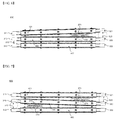
- FIG. 5 is a side view typically showing a structure in which unit modules, one of which is shown in FIG. 3 , are stacked such that expansion opening parts of the unit modules faces each other
- FIG. 6 is a side view typically showing a case in which the battery cells abnormally operate in the structure shown in FIG. 5 .
- a battery cell having electrode terminals 110 and 120 formed at opposite ends thereof and another battery cell having electrode terminals 111 and 121 formed at opposite ends thereof are mounted in a cell housing in a state in which the battery cells are connected in parallel to each other (310 and 320).
- the cell housing member includes a pair of a first housing 200a and a second housing 200b coupled to each other.
- the first housing 200a is provided at the outer surface thereof with protrusions 210a, 220a, 230a, and 250a to define a coolant channel, which are formed at a region of the first housing 200a excluding an expansion opening part 270.
- the second housing 200b is provided at the outer surface thereof with protrusions 210b, 220b, 230b, 240b, and 250b to define a coolant channel.
- a battery cell assembly 600 is configured to have a structure in which unit modules 400, 401, and 402, each of which is configured to have the same structure as a unit module of FIG. 3 including two or more battery cells mounted in a cell housing member, are stacked in a state in which the modules 400, 401, and 402 are connected in series to one another (510 and 520) such that expansion opening parts 270 and 271 face each other and protrusions are formed at the outer surfaces of the respective cell housings such that the protrusions correspond to each other excluding the expansion opening parts 270 and 271 to define a coolant channel among the stacked unit modules 400, 401, and 402.
- each of the unit modules 401 and 402 is configured to have a structure in which two battery cells each having electrode terminals formed at opposite ends thereof are mounted in a cell housing member in a state in which the battery cells are connected in parallel to each other (311, 321, 312, and 322).
- FIG. 7 is a side view typically showing another embodiment of a case in which battery cells abnormally operate.
- a cell housing member 400 is provided at an upper surface and a lower surface thereof with expansion opening parts 270 and 272, which are diagonally arranged.
- a cell housing member 402 is provided at an upper surface with an expansion opening part 273 and a cell housing member 401 is provided at a lower surface with an expansion opening part 271.
- the expansion opening parts 270 and 271 and the expansion opening parts 272 and 273 are diagonally arranged in a state in which the cell housing member 400 is between the expansion opening parts 270 and 271 and the expansion opening parts 272 and 273.
- the cell housing member 402 is the lowermost cell housing member.
- the cell housing member 402 is fixed to a module case (not shown).
- a cathode slurry was prepared by putting and mixing 95 weight percent of LiCoO 2 , 2.5 weight percent of Super-P, and 2.5 weight percent of PVdf in NMP.
- the cathode slurry was coated on an aluminum foil having a thickness of 20 ⁇ m such that the cathode slurry has a thickness of 200 ⁇ m, rolled, and dried to manufacture a cathode.
- An anode slurry was prepared by putting and mixing 96 weight percent of graphite, 1.5 weight percent of Super-P, and 2.5 weight percent of SBR/CMC in water.
- the anode slurry was coated on a copper foil having a thickness of 10 ⁇ m, rolled, and dried to manufacture an anode.
- An electrode assembly including a cathode, an anode, and a separator disposed between the cathode and the anode was mounted in a battery case formed of a laminate sheet including a metal layer and a resin layer, an a carbonate electrolytic solution containing 1 mole of LiPF 6 dissolved therein was impregnated as an electrolyte, and a battery case was thermally bonded along the outer circumference of an electrode assembly receiving unit to manufacture a pouch-shaped battery cell having a sealed portion.
- pouch-shaped battery cells manufactured according to Example 1 were charged and discharged 100 times under a temperature condition of 45 °C, a charging condition of 1.0 C, and a discharging condition of 1.0 C.
- Two pouch-shaped battery cells were mounted in a cell housing member in a state in which the pouch-shaped battery cells were connected in parallel to each other to manufacture a unit module.
- a plurality of unit modules was stacked in a state in which the unit modules were connected in series to each other to manufacture a battery cell assembly according to the present invention.
- An expansion opening part was formed at the lower surface of the uppermost unit module, an expansion opening part was formed at the upper surface of an adjacent unit module stacked under the uppermost unit module, and the unit modules were arranged such that the expansion opening parts faced each other.
- the uppermost unit module and the adjacent unit module stacked under the uppermost unit module were constituted by the pouch-shaped battery cells manufactured according to Example 2.
- the remaining unit modules excluding the uppermost battery cell and the uppermost unit module were constituted by the pouch-shaped battery cells manufactured according to Example 1.
- Two pouch-shaped battery cells were mounted in a cell housing member in a state in which the pouch-shaped battery cells were connected in parallel to each other to manufacture a unit module.
- a plurality of unit modules was stacked in a state in which the unit modules were connected in series to each other to manufacture a battery cell assembly according to the present invention.
- An expansion opening part was formed at the lower surface of the uppermost unit module and an expansion opening part was formed at the upper surface of the lowermost unit module.
- Expansion opening parts were formed at the upper surfaces and the lower surfaces of the remaining unit modules excluding the uppermost unit module and the lowermost unit module such that the expansion opening parts formed at the upper surfaces and the lower surfaces of the remaining unit modules were diagonally arranged.
- a pair of expansion opening parts facing each other and another adjacent pair of expansion opening parts were diagonally arranged.
- All of the unit modules were constituted by the pouch-shaped battery cells manufactured according to Example 2.
- Two pouch-shaped battery cells were mounted in a cell housing member in a state in which the pouch-shaped battery cells were connected in parallel to each other to manufacture a unit module.
- a plurality of unit modules was stacked in a state in which the unit modules were connected in series to each other to manufacture a battery cell assembly according to the present invention.
- An expansion opening part was formed at the lower surface of the uppermost unit module and an expansion opening part was formed at the upper surface of the lowermost unit module.
- Expansion opening parts were formed at the upper surfaces and the lower surfaces of the remaining unit modules excluding the uppermost unit module and the lowermost unit module such that the expansion opening parts formed at the upper surfaces and the lower surfaces of the remaining unit modules were diagonally arranged.
- a pair of expansion opening parts facing each other and another adjacent pair of expansion opening parts were diagonally arranged.
- One of the remaining unit modules excluding the uppermost unit module and the lowermost unit module was constituted by the pouch-shaped battery cells manufactured according to Example 2 and the other unit modules were constituted by the pouch-shaped battery cells manufactured according to Example 1.
- Two pouch-shaped battery cells were mounted in a cell housing member in a state in which the pouch-shaped battery cells were connected in parallel to each other to manufacture a unit module.
- a plurality of unit modules was stacked in a state in which the unit modules were connected in series to each other to manufacture a battery cell assembly according to the present invention.
- An expansion opening part was formed only at the upper surface of the uppermost unit module.
- the uppermost unit module and an adjacent unit module stacked under the uppermost unit module were constituted by the pouch-shaped battery cells manufactured according to Example 2.
- the remaining unit modules excluding the uppermost battery cell and the uppermost unit module were constituted by the pouch-shaped battery cells manufactured according to Example 1.
- Two pouch-shaped battery cells were mounted in a cell housing member in a state in which the pouch-shaped battery cells were connected in parallel to each other to manufacture a unit module.
- a plurality of unit modules was stacked in a state in which the unit modules were connected in series to each other to manufacture a battery cell assembly according to the present invention.
- An expansion opening part was formed only at the upper surface of the uppermost unit module.
- All of the unit modules were constituted by the pouch-shaped battery cells manufactured according to Example 2.
- Two pouch-shaped battery cells were mounted in a cell housing member in a state in which the pouch-shaped battery cells were connected in parallel to each other to manufacture a unit module.
- a plurality of unit modules was stacked in a state in which the unit modules were connected in series to each other to manufacture a battery cell assembly according to the present invention.
- An expansion opening part was formed only at the upper surface of the uppermost unit module.
- One of the remaining unit modules excluding the uppermost unit module and the lowermost unit module was constituted by the pouch-shaped battery cells manufactured according to Example 2 and the other unit modules were constituted by the pouch-shaped battery cells manufactured according to Example 1.
- Example 4 Upon comparison between Example 4 and Comparative example 2, it can be seen that the unit modules according to Comparative example 2 were not cut off because force to rupture the parallel connection between the battery cells constituting the uppermost unit module was low, whereas the unit modules according to Example 4 were cut off within a short time because expansion force of the battery cells was concentrated.
- Example 5 Upon comparison between Example 5 and Comparative example 3, it can be seen that safety of the battery cell assembly according to the present invention was secured even when any one of the battery cells constituting the remaining stacked unit modules excluding the outermost unit modules abnormally operated.
- a battery cell assembly according to the present invention is configured to have a structure in which an expansion opening part is formed at one surface or opposite surfaces of each of at least two cell housing members and battery cells are stacked such that the at least two expansion opening parts face each other.
- the cut-off effect due to rupture of the electrical connection is achieved by abnormal operation of the battery cells which are laterally stacked as well as abnormal operation of the battery cells mounted in the outermost unit modules, thereby achieving higher safety and operational reliability than in the conventional battery cell assembly.
Landscapes
- Engineering & Computer Science (AREA)
- Chemical Kinetics & Catalysis (AREA)
- Electrochemistry (AREA)
- General Chemical & Material Sciences (AREA)
- Chemical & Material Sciences (AREA)
- Power Engineering (AREA)
- Life Sciences & Earth Sciences (AREA)
- Sustainable Energy (AREA)
- Sustainable Development (AREA)
- Transportation (AREA)
- Mechanical Engineering (AREA)
- Manufacturing & Machinery (AREA)
- Battery Mounting, Suspending (AREA)
- Secondary Cells (AREA)
- Sealing Battery Cases Or Jackets (AREA)
- Connection Of Batteries Or Terminals (AREA)
Claims (21)
- Batteriezellenanordnung (600), umfassend- eine Mehrzahl von Batteriezellen (100), welche gestapelt sind, während diese miteinander elektrisch verbunden sind, wobei eine oder mehrere der Batteriezellen (100) in jedem Zellengehäuseelement (400) in einem Zustand angebracht sind, in welchem entgegengesetzte Seiten der Batteriezellen (100) durch jedes Zellengehäuseelement (400) umgeben sind, ausgenommen Elektrodenanschlüsse (110, 120) der Batteriezellen (100),- ein Expansionsöffnungsteil (270), durch welches ein Abschnitt eines Hauptkörpers jeder der Batteriezellen (100) nach außen freigelegt ist, wenn die Batteriezellen (100) expandieren, welches an einer Fläche oder entgegengesetzten Flächen von jedem der wenigstens zwei Zellengehäuseelemente (400) ausgebildet ist, unddie Batteriezellen (100) derart gestapelt sind, dass die wenigstens zwei Expansionsöffnungsteile (270) einander zugewandt sind.
- Batteriezellenanordnung (600) nach Anspruch 1, wobei die zwei oder mehreren Batteriezellen, welche an jedem Zellengehäuseelement angebracht sind, miteinander parallel geschaltet sind.
- Batteriezellenanordnung (600) nach Anspruch 1, wobei die Batteriezellen zwischen den jeweiligen Zellengehäuseelemten (400) miteinander in Reihe geschaltet sind.
- Batteriezellenanordnung (600) nach Anspruch 1, wobei jedes der Expansionsöffnungsteile (270) an jedem Zellengehäuseelement (400) in der Gestalt einer Öffnung ausgebildet ist, durch welche ein Abschnitt des Hauptkörpers einer entsprechenden der Batteriezellen (100) auch in einem Zustand freigelegt ist, in welchem die Batteriezelle (100) nicht expandiert.
- Batteriezellenanordnung (600) nach Anspruch 1, wobei jedes der Expansionsöffnungsteile (270) an jedem Zellengehäuseelement (400) in der Gestalt einer Nut ausgebildet ist, welche dazu eingerichtet ist, durchbrochen zu werden, wenn eine entsprechende der Batteriezellen (100) derart expandiert, dass ein Abschnitt des Hauptkörpers der Batteriezelle (100) freigelegt ist.
- Batteriezellenanordnung (600) nach Anspruch 1, wobei jedes der Expansionsöffnungsteile (270) in einer Position ausgebildet ist, in welcher jedes Zellengehäuseelement (400) zu einem Elektrodenanschluss-Verbindungsbereich zwischen den Batteriezellen (100) benachbart ist, so dass der Elektrodenanschluss-Verbindungsbereich durchbrochen ist, wenn die Batteriezellen (100) expandieren und die Batteriezellenanordnung (600) somit abgeschaltet ist.
- Batteriezellenanordnung (600) nach Anspruch 6, wobei jedes der Expansionsöffnungsteile (270) an einem Seitenteil jedes Zellengehäuseelements (400) zu dem Elektrodenanschluss-Verbindungsbereich benachbart ausgebildet ist.
- Batteriezellenanordnung (600) nach Anspruch 1, wobei jedes der Expansionsöffnungsteile (270) einen Bereich, welcher zu 10 bis 50 % zu einem gesamten Bereich einer Fläche jedes Zellengehäuseelements (400) äquivalenten ist, an einer Position von jedem Zellengehäuseelement (400), benachbart zu einem Elektrodenanschluss-Verbindungsbereich zwischen den Batteriezellen, aufweist.
- Batteriezellenanordnung nach Anspruch 1, wobei eines der Expansionsöffnungsteile an einer unteren Fläche eines obersten der Zellengehäuseelemente ausgebildet ist.
- Batteriezellenanordnung nach Anspruch 1, wobei eines der Expansionsöffnungsteile an einer oberen Fläche eines untersten der Zellengehäuseelemente ausgebildet ist.
- Batteriezellenanordnung (600) nach Anspruch 1, wobei die Expansionsöffnungsteile (270) an gegenüberliegenden Flächen der anderen der Zellengehäuseelemente (400), das oberste und das unterste der Zellengehäuseelemente (400) ausgenommen, ausgebildet sind.
- Batteriezellenanordnung (600) nach Anspruch 11, wobei die an gegenüberliegenden Flächen der Zellengehäuseelemente (400) ausgebildeten Expansionsöffnungsteile (270) diagonal angeordnet sind.
- Batteriezellenanordnung (600) nach Anspruch 11, wobei die an gegenüberliegenden Seiten der Zellengehäuseelemente (400) gebildeten Expansionsöffnungsteile (270) einander zugewandt sind.
- Batteriezellenanordnung (600) nach Anspruch 1, wobei ein Paar der Expansionsöffnungsteile (270), welche einander zugewandt sind, und ein anderes benachbartes Paar der Expansionsöffnungsteile (270) diagonal angeordnet sind.
- Batteriezellenanordnung (600) nach Anspruch 1, wobei ein Paar der Expansionsöffnungsteile (270), welche einander zugewandt sind, und ein anderes benachbartes Paar der Expansionsöffnungsteile (270) einander zugewandt sind.
- Batteriezellenanordnung (600) nach Anspruch 1, wobei jedes Zellengehäuseelement (400) ein Paar aus einem ersten Gehäuse (200a) und einem zweiten Gehäuse (200b) umfasst, welche miteinander gekoppelt sind, und wobei das erste Gehäuse (200a) einer ersten der Batteriezellen (100) und das zweite Gehäuse (200b) einer zweiten der Batteriezellen (100), welche zusammen mit der ersten der Batteriezellen (100) eine gestapelte Struktur konstituieren, an äußeren Flächen davon mit Vorsprüngen (210) versehen sind, um Kühlmittelkanäle zu definieren, welche an Bereichen des ersten Gehäuses (200a) und des zweiten Gehäuses (200b), die Expansionsöffnungsteile (270) ausschließend, gebildet sind.
- Batteriezellenanordnung (600) nach Anspruch 16, wobei die Vorsprünge (210) an entsprechenden Positionen ausgebildet sind.
- Batteriezellenanordnung (600) nach Anspruch 1, wobei jede der Batteriezellen (100) dazu eingerichtet ist, eine Struktur aufzuweisen, in welcher eine Elektrodenanordnung in einem Batteriekasten angebracht ist, welche aus einer Laminatbahn gebildet ist, welche eine Metallschicht und eine Harz/Kunststoffschicht umfasst, und wobei der Batteriekasten entlang eines äußeren Umfangs einer Elektrodenanordnungs-Aufnahmeeinheit thermisch verbunden ist, um einen abgedichteten Abschnitt zu bilden.
- Batteriemodul, welches eine Batteriezellenanordnung (600) nach Anspruch 1 umfasst.
- Batteriepack, welcher ein Batteriemodul nach Anspruch 19 umfasst.
- Vorrichtung, welche einen Batteriepack nach Anspruch 20 als eine elektrische Energiequelle oder eine Energiequelle verwendet.
Applications Claiming Priority (2)
| Application Number | Priority Date | Filing Date | Title |
|---|---|---|---|
| KR20120020710 | 2012-02-29 | ||
| PCT/KR2013/001590 WO2013129844A1 (ko) | 2012-02-29 | 2013-02-27 | 안전성이 향상된 전지셀 어셈블리 및 이를 포함하는 전지모듈 |
Publications (3)
| Publication Number | Publication Date |
|---|---|
| EP2800169A1 EP2800169A1 (de) | 2014-11-05 |
| EP2800169A4 EP2800169A4 (de) | 2015-03-04 |
| EP2800169B1 true EP2800169B1 (de) | 2016-06-15 |
Family
ID=49082975
Family Applications (1)
| Application Number | Title | Priority Date | Filing Date |
|---|---|---|---|
| EP13755553.8A Active EP2800169B1 (de) | 2012-02-29 | 2013-02-27 | Batteriezellenanordnung mit erhöhter sicherheit und batteriemodul damit |
Country Status (6)
| Country | Link |
|---|---|
| US (1) | US10205153B2 (de) |
| EP (1) | EP2800169B1 (de) |
| JP (1) | JP5866463B2 (de) |
| KR (1) | KR101307985B1 (de) |
| CN (1) | CN104094448B (de) |
| WO (1) | WO2013129844A1 (de) |
Families Citing this family (10)
| Publication number | Priority date | Publication date | Assignee | Title |
|---|---|---|---|---|
| KR101583873B1 (ko) * | 2013-10-22 | 2016-01-08 | 현대자동차주식회사 | 배터리 과충전 방지장치 및 배터리 |
| KR101704127B1 (ko) * | 2014-11-14 | 2017-02-07 | 현대자동차주식회사 | 스웰링 cid 작동 신뢰성이 향상되는 배터리 시스템 |
| US10516146B2 (en) * | 2016-10-28 | 2019-12-24 | Tiveni Mergeco, Inc. | Fixation of a battery module in a battery module compartment of an energy storage system |
| US10272758B2 (en) * | 2016-11-02 | 2019-04-30 | Proterra Inc. | Battery system of an electric vehicle |
| KR102258822B1 (ko) | 2017-04-25 | 2021-06-07 | 주식회사 엘지에너지솔루션 | 재활용 가능한 파우치형 이차전지, 이를 포함하는 배터리 모듈 및 배터리 모듈 재활용 방법 |
| KR102163656B1 (ko) * | 2017-06-27 | 2020-10-08 | 주식회사 엘지화학 | 배터리 모듈과 이를 포함하는 배터리 팩 및 자동차 |
| KR102256605B1 (ko) * | 2017-07-06 | 2021-05-26 | 주식회사 엘지에너지솔루션 | 배터리 모듈 및 이를 포함하는 배터리 팩 |
| JP7200140B2 (ja) * | 2018-01-30 | 2023-01-06 | 三洋電機株式会社 | バッテリシステムのショート電流遮断方法及びバッテリシステム、バッテリシステムを備える電動車両及び蓄電装置 |
| KR102176697B1 (ko) | 2018-06-29 | 2020-11-09 | 주식회사 엘지화학 | 단위체를 포함하는 배터리 모듈 |
| KR102380225B1 (ko) * | 2019-03-06 | 2022-03-28 | 주식회사 엘지에너지솔루션 | 화염의 외부 노출을 방지할 수 있는 구조를 갖는 ess 모듈 및 이를 포함하는 배터리 팩 |
Family Cites Families (18)
| Publication number | Priority date | Publication date | Assignee | Title |
|---|---|---|---|---|
| KR100515572B1 (ko) | 2000-02-08 | 2005-09-20 | 주식회사 엘지화학 | 중첩 전기화학 셀 및 그의 제조 방법 |
| JP2004111219A (ja) | 2002-09-18 | 2004-04-08 | Nissan Motor Co Ltd | ラミネート二次電池、複数のラミネート二次電池からなる組電池モジュール、複数の組電池モジュールからなる組電池ならびにこれらいずれかの電池を搭載した電気自動車 |
| US7083878B2 (en) | 2003-02-27 | 2006-08-01 | Mitsubishi Chemical Corporation | Nonaqueous electrolytic solution and lithium secondary battery |
| JP5044884B2 (ja) * | 2004-07-01 | 2012-10-10 | トヨタ自動車株式会社 | 組電池 |
| JP4905861B2 (ja) | 2005-02-10 | 2012-03-28 | 日立化成工業株式会社 | エネルギーデバイス電極用バインダ樹脂エマルション及びこれを用いたエネルギーデバイス電極並びにエネルギーデバイス |
| EP1878071B1 (de) | 2005-05-02 | 2012-08-15 | Lg Chem, Ltd. | Verbessertes mittelgrosses oder grosses batteriepack mit erhöhter sicherheit |
| KR100881641B1 (ko) * | 2005-05-10 | 2009-02-04 | 주식회사 엘지화학 | 안전 시스템을 구비한 중대형 전지팩 |
| KR100903185B1 (ko) * | 2005-05-02 | 2009-06-17 | 주식회사 엘지화학 | 향상된 안전성의 개선된 중대형 전지팩 |
| JP5110599B2 (ja) | 2005-05-17 | 2012-12-26 | エルジー・ケム・リミテッド | 多重積層電気化学セルを含む電気化学素子用のバインダー |
| KR100895203B1 (ko) | 2006-05-15 | 2009-05-06 | 주식회사 엘지화학 | 중대형 전지모듈 |
| WO2008044683A1 (en) | 2006-10-10 | 2008-04-17 | Panasonic Corporation | Negative electrode for nonaqueous electrolyte secondary battery |
| CN102386354B (zh) * | 2007-02-21 | 2014-03-12 | 日本电气株式会社 | 封装电池、层叠叠层电池组、以及覆膜电池 |
| US7943252B2 (en) | 2007-11-21 | 2011-05-17 | Lg Chem, Ltd. | Battery module of improved safety and middle or large-sized battery pack containing the same |
| KR20090131573A (ko) * | 2008-06-18 | 2009-12-29 | 현대자동차주식회사 | 배터리 과충전시 전원차단장치 |
| KR101169205B1 (ko) * | 2008-06-25 | 2012-07-26 | 주식회사 엘지화학 | 안전성이 향상된 중대형 전지팩 |
| JP2010092833A (ja) * | 2008-09-09 | 2010-04-22 | Toyota Motor Corp | 蓄電装置 |
| JP5540070B2 (ja) | 2009-04-01 | 2014-07-02 | エルジー・ケム・リミテッド | 電池モジュール及び電池パック |
| JP2011249107A (ja) * | 2010-05-26 | 2011-12-08 | Panasonic Corp | 蓄電モジュール |
-
2013
- 2013-02-27 EP EP13755553.8A patent/EP2800169B1/de active Active
- 2013-02-27 WO PCT/KR2013/001590 patent/WO2013129844A1/ko not_active Ceased
- 2013-02-27 KR KR1020130021226A patent/KR101307985B1/ko active Active
- 2013-02-27 JP JP2014556493A patent/JP5866463B2/ja active Active
- 2013-02-27 CN CN201380008317.3A patent/CN104094448B/zh active Active
-
2014
- 2014-07-30 US US14/446,486 patent/US10205153B2/en active Active
Also Published As
| Publication number | Publication date |
|---|---|
| KR101307985B1 (ko) | 2013-09-12 |
| CN104094448B (zh) | 2016-08-17 |
| JP2015510673A (ja) | 2015-04-09 |
| US20140335397A1 (en) | 2014-11-13 |
| KR20130099875A (ko) | 2013-09-06 |
| JP5866463B2 (ja) | 2016-02-17 |
| CN104094448A (zh) | 2014-10-08 |
| WO2013129844A1 (ko) | 2013-09-06 |
| EP2800169A4 (de) | 2015-03-04 |
| EP2800169A1 (de) | 2014-11-05 |
| US10205153B2 (en) | 2019-02-12 |
Similar Documents
| Publication | Publication Date | Title |
|---|---|---|
| EP2800169B1 (de) | Batteriezellenanordnung mit erhöhter sicherheit und batteriemodul damit | |
| CN101861666B (zh) | 安全性提高的电池模块和含有所述电池模块的中型或大型电池组 | |
| EP3512008B1 (de) | Batteriemodul sowie batteriepack und fahrzeug damit | |
| EP2768047B1 (de) | Batteriepackung mit erhöhter sicherheit | |
| EP2741391B1 (de) | Batteriepack mit verbesserter sicherheit | |
| EP2672548B1 (de) | Batteriepack mit erhöhter sicherheit | |
| EP2685527B1 (de) | Batteriepack mit erhöhter sicherheit | |
| EP2156488B1 (de) | Batteriezelle mit verbesserter sicherheit | |
| JP5575761B2 (ja) | 安全性を改良した中型又は大型バッテリーパック | |
| US20130095353A1 (en) | Electrochemical cell having a safety device | |
| US9843032B2 (en) | Battery module | |
| KR102436424B1 (ko) | 이차 전지 | |
| KR101487152B1 (ko) | 단위모듈 어셈블리 및 이를 포함하는 전지모듈 | |
| EP3367458B1 (de) | Sekundäre zelle für eine traktionsbatterie und herstellungsverfahren einer sekundärzelle | |
| US20250192237A1 (en) | Secondary battery and battery pack including the same | |
| EP4607668A1 (de) | Batteriezellen und batteriemodule | |
| KR101678940B1 (ko) | 안전성이 향상된 전지셀 및 그의 제조방법 | |
| KR101566574B1 (ko) | 물과 무기산화물의 혼합물을 적용한 고안전성 리튬 이차전지 |
Legal Events
| Date | Code | Title | Description |
|---|---|---|---|
| PUAI | Public reference made under article 153(3) epc to a published international application that has entered the european phase |
Free format text: ORIGINAL CODE: 0009012 |
|
| 17P | Request for examination filed |
Effective date: 20140729 |
|
| AK | Designated contracting states |
Kind code of ref document: A1 Designated state(s): AL AT BE BG CH CY CZ DE DK EE ES FI FR GB GR HR HU IE IS IT LI LT LU LV MC MK MT NL NO PL PT RO RS SE SI SK SM TR |
|
| A4 | Supplementary search report drawn up and despatched |
Effective date: 20150202 |
|
| RIC1 | Information provided on ipc code assigned before grant |
Ipc: H01M 2/02 20060101ALI20150127BHEP Ipc: H01M 2/22 20060101AFI20150127BHEP Ipc: H01M 2/10 20060101ALI20150127BHEP Ipc: H01M 2/20 20060101ALI20150127BHEP Ipc: H01M 2/34 20060101ALI20150127BHEP |
|
| DAX | Request for extension of the european patent (deleted) | ||
| REG | Reference to a national code |
Ref country code: DE Ref legal event code: R079 Ref document number: 602013008628 Country of ref document: DE Free format text: PREVIOUS MAIN CLASS: H01M0002220000 Ipc: H01M0002100000 |
|
| GRAP | Despatch of communication of intention to grant a patent |
Free format text: ORIGINAL CODE: EPIDOSNIGR1 |
|
| RIC1 | Information provided on ipc code assigned before grant |
Ipc: B60L 3/12 20060101ALI20160104BHEP Ipc: H01M 2/10 20060101ALI20160104BHEP Ipc: H01M 2/20 20060101ALI20160104BHEP Ipc: B60L 11/18 20060101ALI20160104BHEP Ipc: H01M 10/613 20140101ALN20160104BHEP Ipc: H01M 2/34 20060101ALI20160104BHEP Ipc: H01M 10/625 20140101ALN20160104BHEP Ipc: H01M 2/22 20060101AFI20160104BHEP Ipc: H01M 10/647 20140101ALN20160104BHEP Ipc: B60L 3/00 20060101ALI20160104BHEP Ipc: H01M 10/6551 20140101ALN20160104BHEP Ipc: H01M 2/02 20060101ALI20160104BHEP |
|
| RIC1 | Information provided on ipc code assigned before grant |
Ipc: B60L 3/00 20060101ALI20160113BHEP Ipc: H01M 10/6551 20140101ALN20160113BHEP Ipc: H01M 2/10 20060101AFI20160113BHEP Ipc: B60L 11/18 20060101ALI20160113BHEP Ipc: H01M 2/34 20060101ALI20160113BHEP Ipc: H01M 2/02 20060101ALI20160113BHEP Ipc: H01M 2/20 20060101ALI20160113BHEP Ipc: H01M 10/613 20140101ALN20160113BHEP Ipc: H01M 10/647 20140101ALN20160113BHEP Ipc: B60L 3/12 20060101ALI20160113BHEP Ipc: H01M 10/625 20140101ALN20160113BHEP |
|
| INTG | Intention to grant announced |
Effective date: 20160129 |
|
| RIN1 | Information on inventor provided before grant (corrected) |
Inventor name: YANG, JUNGHOON Inventor name: KIM, YOJIN Inventor name: CHOI, SEUNGDON |
|
| GRAS | Grant fee paid |
Free format text: ORIGINAL CODE: EPIDOSNIGR3 |
|
| GRAA | (expected) grant |
Free format text: ORIGINAL CODE: 0009210 |
|
| AK | Designated contracting states |
Kind code of ref document: B1 Designated state(s): AL AT BE BG CH CY CZ DE DK EE ES FI FR GB GR HR HU IE IS IT LI LT LU LV MC MK MT NL NO PL PT RO RS SE SI SK SM TR |
|
| REG | Reference to a national code |
Ref country code: CH Ref legal event code: EP Ref country code: GB Ref legal event code: FG4D |
|
| REG | Reference to a national code |
Ref country code: IE Ref legal event code: FG4D |
|
| REG | Reference to a national code |
Ref country code: AT Ref legal event code: REF Ref document number: 806884 Country of ref document: AT Kind code of ref document: T Effective date: 20160715 |
|
| REG | Reference to a national code |
Ref country code: DE Ref legal event code: R096 Ref document number: 602013008628 Country of ref document: DE |
|
| REG | Reference to a national code |
Ref country code: LT Ref legal event code: MG4D |
|
| REG | Reference to a national code |
Ref country code: NL Ref legal event code: MP Effective date: 20160615 |
|
| PG25 | Lapsed in a contracting state [announced via postgrant information from national office to epo] |
Ref country code: FI Free format text: LAPSE BECAUSE OF FAILURE TO SUBMIT A TRANSLATION OF THE DESCRIPTION OR TO PAY THE FEE WITHIN THE PRESCRIBED TIME-LIMIT Effective date: 20160615 Ref country code: NO Free format text: LAPSE BECAUSE OF FAILURE TO SUBMIT A TRANSLATION OF THE DESCRIPTION OR TO PAY THE FEE WITHIN THE PRESCRIBED TIME-LIMIT Effective date: 20160915 Ref country code: LT Free format text: LAPSE BECAUSE OF FAILURE TO SUBMIT A TRANSLATION OF THE DESCRIPTION OR TO PAY THE FEE WITHIN THE PRESCRIBED TIME-LIMIT Effective date: 20160615 |
|
| REG | Reference to a national code |
Ref country code: AT Ref legal event code: MK05 Ref document number: 806884 Country of ref document: AT Kind code of ref document: T Effective date: 20160615 |
|
| PG25 | Lapsed in a contracting state [announced via postgrant information from national office to epo] |
Ref country code: NL Free format text: LAPSE BECAUSE OF FAILURE TO SUBMIT A TRANSLATION OF THE DESCRIPTION OR TO PAY THE FEE WITHIN THE PRESCRIBED TIME-LIMIT Effective date: 20160615 Ref country code: RS Free format text: LAPSE BECAUSE OF FAILURE TO SUBMIT A TRANSLATION OF THE DESCRIPTION OR TO PAY THE FEE WITHIN THE PRESCRIBED TIME-LIMIT Effective date: 20160615 Ref country code: GR Free format text: LAPSE BECAUSE OF FAILURE TO SUBMIT A TRANSLATION OF THE DESCRIPTION OR TO PAY THE FEE WITHIN THE PRESCRIBED TIME-LIMIT Effective date: 20160916 Ref country code: SE Free format text: LAPSE BECAUSE OF FAILURE TO SUBMIT A TRANSLATION OF THE DESCRIPTION OR TO PAY THE FEE WITHIN THE PRESCRIBED TIME-LIMIT Effective date: 20160615 Ref country code: LV Free format text: LAPSE BECAUSE OF FAILURE TO SUBMIT A TRANSLATION OF THE DESCRIPTION OR TO PAY THE FEE WITHIN THE PRESCRIBED TIME-LIMIT Effective date: 20160615 Ref country code: HR Free format text: LAPSE BECAUSE OF FAILURE TO SUBMIT A TRANSLATION OF THE DESCRIPTION OR TO PAY THE FEE WITHIN THE PRESCRIBED TIME-LIMIT Effective date: 20160615 |
|
| REG | Reference to a national code |
Ref country code: FR Ref legal event code: PLFP Year of fee payment: 5 |
|
| PG25 | Lapsed in a contracting state [announced via postgrant information from national office to epo] |
Ref country code: SK Free format text: LAPSE BECAUSE OF FAILURE TO SUBMIT A TRANSLATION OF THE DESCRIPTION OR TO PAY THE FEE WITHIN THE PRESCRIBED TIME-LIMIT Effective date: 20160615 Ref country code: RO Free format text: LAPSE BECAUSE OF FAILURE TO SUBMIT A TRANSLATION OF THE DESCRIPTION OR TO PAY THE FEE WITHIN THE PRESCRIBED TIME-LIMIT Effective date: 20160615 Ref country code: IT Free format text: LAPSE BECAUSE OF FAILURE TO SUBMIT A TRANSLATION OF THE DESCRIPTION OR TO PAY THE FEE WITHIN THE PRESCRIBED TIME-LIMIT Effective date: 20160615 Ref country code: CZ Free format text: LAPSE BECAUSE OF FAILURE TO SUBMIT A TRANSLATION OF THE DESCRIPTION OR TO PAY THE FEE WITHIN THE PRESCRIBED TIME-LIMIT Effective date: 20160615 Ref country code: EE Free format text: LAPSE BECAUSE OF FAILURE TO SUBMIT A TRANSLATION OF THE DESCRIPTION OR TO PAY THE FEE WITHIN THE PRESCRIBED TIME-LIMIT Effective date: 20160615 Ref country code: IS Free format text: LAPSE BECAUSE OF FAILURE TO SUBMIT A TRANSLATION OF THE DESCRIPTION OR TO PAY THE FEE WITHIN THE PRESCRIBED TIME-LIMIT Effective date: 20161015 |
|
| PG25 | Lapsed in a contracting state [announced via postgrant information from national office to epo] |
Ref country code: AT Free format text: LAPSE BECAUSE OF FAILURE TO SUBMIT A TRANSLATION OF THE DESCRIPTION OR TO PAY THE FEE WITHIN THE PRESCRIBED TIME-LIMIT Effective date: 20160615 Ref country code: PT Free format text: LAPSE BECAUSE OF FAILURE TO SUBMIT A TRANSLATION OF THE DESCRIPTION OR TO PAY THE FEE WITHIN THE PRESCRIBED TIME-LIMIT Effective date: 20161017 Ref country code: ES Free format text: LAPSE BECAUSE OF FAILURE TO SUBMIT A TRANSLATION OF THE DESCRIPTION OR TO PAY THE FEE WITHIN THE PRESCRIBED TIME-LIMIT Effective date: 20160615 Ref country code: PL Free format text: LAPSE BECAUSE OF FAILURE TO SUBMIT A TRANSLATION OF THE DESCRIPTION OR TO PAY THE FEE WITHIN THE PRESCRIBED TIME-LIMIT Effective date: 20160615 Ref country code: SM Free format text: LAPSE BECAUSE OF FAILURE TO SUBMIT A TRANSLATION OF THE DESCRIPTION OR TO PAY THE FEE WITHIN THE PRESCRIBED TIME-LIMIT Effective date: 20160615 Ref country code: BE Free format text: LAPSE BECAUSE OF FAILURE TO SUBMIT A TRANSLATION OF THE DESCRIPTION OR TO PAY THE FEE WITHIN THE PRESCRIBED TIME-LIMIT Effective date: 20160615 |
|
| REG | Reference to a national code |
Ref country code: DE Ref legal event code: R097 Ref document number: 602013008628 Country of ref document: DE |
|
| PLBE | No opposition filed within time limit |
Free format text: ORIGINAL CODE: 0009261 |
|
| STAA | Information on the status of an ep patent application or granted ep patent |
Free format text: STATUS: NO OPPOSITION FILED WITHIN TIME LIMIT |
|
| 26N | No opposition filed |
Effective date: 20170316 |
|
| PG25 | Lapsed in a contracting state [announced via postgrant information from national office to epo] |
Ref country code: DK Free format text: LAPSE BECAUSE OF FAILURE TO SUBMIT A TRANSLATION OF THE DESCRIPTION OR TO PAY THE FEE WITHIN THE PRESCRIBED TIME-LIMIT Effective date: 20160615 |
|
| PG25 | Lapsed in a contracting state [announced via postgrant information from national office to epo] |
Ref country code: SI Free format text: LAPSE BECAUSE OF FAILURE TO SUBMIT A TRANSLATION OF THE DESCRIPTION OR TO PAY THE FEE WITHIN THE PRESCRIBED TIME-LIMIT Effective date: 20160615 |
|
| PG25 | Lapsed in a contracting state [announced via postgrant information from national office to epo] |
Ref country code: MC Free format text: LAPSE BECAUSE OF FAILURE TO SUBMIT A TRANSLATION OF THE DESCRIPTION OR TO PAY THE FEE WITHIN THE PRESCRIBED TIME-LIMIT Effective date: 20160615 |
|
| REG | Reference to a national code |
Ref country code: CH Ref legal event code: PL |
|
| PG25 | Lapsed in a contracting state [announced via postgrant information from national office to epo] |
Ref country code: CH Free format text: LAPSE BECAUSE OF NON-PAYMENT OF DUE FEES Effective date: 20170228 Ref country code: LI Free format text: LAPSE BECAUSE OF NON-PAYMENT OF DUE FEES Effective date: 20170228 |
|
| REG | Reference to a national code |
Ref country code: IE Ref legal event code: MM4A |
|
| PG25 | Lapsed in a contracting state [announced via postgrant information from national office to epo] |
Ref country code: LU Free format text: LAPSE BECAUSE OF NON-PAYMENT OF DUE FEES Effective date: 20170227 |
|
| REG | Reference to a national code |
Ref country code: FR Ref legal event code: PLFP Year of fee payment: 6 |
|
| PG25 | Lapsed in a contracting state [announced via postgrant information from national office to epo] |
Ref country code: IE Free format text: LAPSE BECAUSE OF NON-PAYMENT OF DUE FEES Effective date: 20170227 |
|
| PG25 | Lapsed in a contracting state [announced via postgrant information from national office to epo] |
Ref country code: MT Free format text: LAPSE BECAUSE OF NON-PAYMENT OF DUE FEES Effective date: 20170227 |
|
| PG25 | Lapsed in a contracting state [announced via postgrant information from national office to epo] |
Ref country code: AL Free format text: LAPSE BECAUSE OF FAILURE TO SUBMIT A TRANSLATION OF THE DESCRIPTION OR TO PAY THE FEE WITHIN THE PRESCRIBED TIME-LIMIT Effective date: 20160615 |
|
| PG25 | Lapsed in a contracting state [announced via postgrant information from national office to epo] |
Ref country code: HU Free format text: LAPSE BECAUSE OF FAILURE TO SUBMIT A TRANSLATION OF THE DESCRIPTION OR TO PAY THE FEE WITHIN THE PRESCRIBED TIME-LIMIT; INVALID AB INITIO Effective date: 20130227 |
|
| PG25 | Lapsed in a contracting state [announced via postgrant information from national office to epo] |
Ref country code: BG Free format text: LAPSE BECAUSE OF FAILURE TO SUBMIT A TRANSLATION OF THE DESCRIPTION OR TO PAY THE FEE WITHIN THE PRESCRIBED TIME-LIMIT Effective date: 20160615 |
|
| PG25 | Lapsed in a contracting state [announced via postgrant information from national office to epo] |
Ref country code: CY Free format text: LAPSE BECAUSE OF FAILURE TO SUBMIT A TRANSLATION OF THE DESCRIPTION OR TO PAY THE FEE WITHIN THE PRESCRIBED TIME-LIMIT Effective date: 20160615 |
|
| PG25 | Lapsed in a contracting state [announced via postgrant information from national office to epo] |
Ref country code: MK Free format text: LAPSE BECAUSE OF FAILURE TO SUBMIT A TRANSLATION OF THE DESCRIPTION OR TO PAY THE FEE WITHIN THE PRESCRIBED TIME-LIMIT Effective date: 20160615 |
|
| PG25 | Lapsed in a contracting state [announced via postgrant information from national office to epo] |
Ref country code: TR Free format text: LAPSE BECAUSE OF FAILURE TO SUBMIT A TRANSLATION OF THE DESCRIPTION OR TO PAY THE FEE WITHIN THE PRESCRIBED TIME-LIMIT Effective date: 20160615 |
|
| REG | Reference to a national code |
Ref country code: DE Ref legal event code: R079 Ref document number: 602013008628 Country of ref document: DE Free format text: PREVIOUS MAIN CLASS: H01M0002100000 Ipc: H01M0050200000 |
|
| REG | Reference to a national code |
Ref country code: DE Ref legal event code: R081 Ref document number: 602013008628 Country of ref document: DE Owner name: LG ENERGY SOLUTION LTD., KR Free format text: FORMER OWNER: LG CHEM, LTD., SEOUL, KR Ref country code: DE Ref legal event code: R081 Ref document number: 602013008628 Country of ref document: DE Owner name: LG ENERGY SOLUTION, LTD., KR Free format text: FORMER OWNER: LG CHEM, LTD., SEOUL, KR |
|
| P01 | Opt-out of the competence of the unified patent court (upc) registered |
Effective date: 20230512 |
|
| REG | Reference to a national code |
Ref country code: GB Ref legal event code: 732E Free format text: REGISTERED BETWEEN 20230824 AND 20230831 |
|
| REG | Reference to a national code |
Ref country code: DE Ref legal event code: R081 Ref document number: 602013008628 Country of ref document: DE Owner name: LG ENERGY SOLUTION, LTD., KR Free format text: FORMER OWNER: LG ENERGY SOLUTION LTD., SEOUL, KR |
|
| PGFP | Annual fee paid to national office [announced via postgrant information from national office to epo] |
Ref country code: GB Payment date: 20260122 Year of fee payment: 14 |
|
| PGFP | Annual fee paid to national office [announced via postgrant information from national office to epo] |
Ref country code: DE Payment date: 20260120 Year of fee payment: 14 |
|
| PGFP | Annual fee paid to national office [announced via postgrant information from national office to epo] |
Ref country code: FR Payment date: 20260121 Year of fee payment: 14 |