EP2800175B1 - Matière active d'électrode négative destinée à un dispositif électrique, électrode négative destinée à un dispositif électrique et dispositif électrique - Google Patents
Matière active d'électrode négative destinée à un dispositif électrique, électrode négative destinée à un dispositif électrique et dispositif électrique Download PDFInfo
- Publication number
- EP2800175B1 EP2800175B1 EP12863433.4A EP12863433A EP2800175B1 EP 2800175 B1 EP2800175 B1 EP 2800175B1 EP 12863433 A EP12863433 A EP 12863433A EP 2800175 B1 EP2800175 B1 EP 2800175B1
- Authority
- EP
- European Patent Office
- Prior art keywords
- negative electrode
- active material
- electrode active
- battery
- mass
- Prior art date
- Legal status (The legal status is an assumption and is not a legal conclusion. Google has not performed a legal analysis and makes no representation as to the accuracy of the status listed.)
- Active
Links
Images




Classifications
-
- H—ELECTRICITY
- H01—ELECTRIC ELEMENTS
- H01M—PROCESSES OR MEANS, e.g. BATTERIES, FOR THE DIRECT CONVERSION OF CHEMICAL ENERGY INTO ELECTRICAL ENERGY
- H01M4/00—Electrodes
- H01M4/02—Electrodes composed of, or comprising, active material
- H01M4/36—Selection of substances as active materials, active masses, active liquids
- H01M4/38—Selection of substances as active materials, active masses, active liquids of elements or alloys
-
- H—ELECTRICITY
- H01—ELECTRIC ELEMENTS
- H01M—PROCESSES OR MEANS, e.g. BATTERIES, FOR THE DIRECT CONVERSION OF CHEMICAL ENERGY INTO ELECTRICAL ENERGY
- H01M4/00—Electrodes
- H01M4/02—Electrodes composed of, or comprising, active material
- H01M4/36—Selection of substances as active materials, active masses, active liquids
- H01M4/38—Selection of substances as active materials, active masses, active liquids of elements or alloys
- H01M4/386—Silicon or alloys based on silicon
-
- C—CHEMISTRY; METALLURGY
- C01—INORGANIC CHEMISTRY
- C01B—NON-METALLIC ELEMENTS; COMPOUNDS THEREOF; METALLOIDS OR COMPOUNDS THEREOF NOT COVERED BY SUBCLASS C01C
- C01B32/00—Carbon; Compounds thereof
- C01B32/90—Carbides
-
- C—CHEMISTRY; METALLURGY
- C22—METALLURGY; FERROUS OR NON-FERROUS ALLOYS; TREATMENT OF ALLOYS OR NON-FERROUS METALS
- C22C—ALLOYS
- C22C13/00—Alloys based on tin
-
- C—CHEMISTRY; METALLURGY
- C22—METALLURGY; FERROUS OR NON-FERROUS ALLOYS; TREATMENT OF ALLOYS OR NON-FERROUS METALS
- C22C—ALLOYS
- C22C30/00—Alloys containing less than 50% by weight of each constituent
- C22C30/04—Alloys containing less than 50% by weight of each constituent containing tin or lead
-
- C—CHEMISTRY; METALLURGY
- C23—COATING METALLIC MATERIAL; COATING MATERIAL WITH METALLIC MATERIAL; CHEMICAL SURFACE TREATMENT; DIFFUSION TREATMENT OF METALLIC MATERIAL; COATING BY VACUUM EVAPORATION, BY SPUTTERING, BY ION IMPLANTATION OR BY CHEMICAL VAPOUR DEPOSITION, IN GENERAL; INHIBITING CORROSION OF METALLIC MATERIAL OR INCRUSTATION IN GENERAL
- C23C—COATING METALLIC MATERIAL; COATING MATERIAL WITH METALLIC MATERIAL; SURFACE TREATMENT OF METALLIC MATERIAL BY DIFFUSION INTO THE SURFACE, BY CHEMICAL CONVERSION OR SUBSTITUTION; COATING BY VACUUM EVAPORATION, BY SPUTTERING, BY ION IMPLANTATION OR BY CHEMICAL VAPOUR DEPOSITION, IN GENERAL
- C23C14/00—Coating by vacuum evaporation, by sputtering or by ion implantation of the coating forming material
- C23C14/06—Coating by vacuum evaporation, by sputtering or by ion implantation of the coating forming material characterised by the coating material
-
- C—CHEMISTRY; METALLURGY
- C23—COATING METALLIC MATERIAL; COATING MATERIAL WITH METALLIC MATERIAL; CHEMICAL SURFACE TREATMENT; DIFFUSION TREATMENT OF METALLIC MATERIAL; COATING BY VACUUM EVAPORATION, BY SPUTTERING, BY ION IMPLANTATION OR BY CHEMICAL VAPOUR DEPOSITION, IN GENERAL; INHIBITING CORROSION OF METALLIC MATERIAL OR INCRUSTATION IN GENERAL
- C23C—COATING METALLIC MATERIAL; COATING MATERIAL WITH METALLIC MATERIAL; SURFACE TREATMENT OF METALLIC MATERIAL BY DIFFUSION INTO THE SURFACE, BY CHEMICAL CONVERSION OR SUBSTITUTION; COATING BY VACUUM EVAPORATION, BY SPUTTERING, BY ION IMPLANTATION OR BY CHEMICAL VAPOUR DEPOSITION, IN GENERAL
- C23C14/00—Coating by vacuum evaporation, by sputtering or by ion implantation of the coating forming material
- C23C14/06—Coating by vacuum evaporation, by sputtering or by ion implantation of the coating forming material characterised by the coating material
- C23C14/14—Metallic material, boron or silicon
-
- C—CHEMISTRY; METALLURGY
- C23—COATING METALLIC MATERIAL; COATING MATERIAL WITH METALLIC MATERIAL; CHEMICAL SURFACE TREATMENT; DIFFUSION TREATMENT OF METALLIC MATERIAL; COATING BY VACUUM EVAPORATION, BY SPUTTERING, BY ION IMPLANTATION OR BY CHEMICAL VAPOUR DEPOSITION, IN GENERAL; INHIBITING CORROSION OF METALLIC MATERIAL OR INCRUSTATION IN GENERAL
- C23C—COATING METALLIC MATERIAL; COATING MATERIAL WITH METALLIC MATERIAL; SURFACE TREATMENT OF METALLIC MATERIAL BY DIFFUSION INTO THE SURFACE, BY CHEMICAL CONVERSION OR SUBSTITUTION; COATING BY VACUUM EVAPORATION, BY SPUTTERING, BY ION IMPLANTATION OR BY CHEMICAL VAPOUR DEPOSITION, IN GENERAL
- C23C14/00—Coating by vacuum evaporation, by sputtering or by ion implantation of the coating forming material
- C23C14/22—Coating by vacuum evaporation, by sputtering or by ion implantation of the coating forming material characterised by the process of coating
- C23C14/34—Sputtering
- C23C14/3464—Sputtering using more than one target
-
- H—ELECTRICITY
- H01—ELECTRIC ELEMENTS
- H01M—PROCESSES OR MEANS, e.g. BATTERIES, FOR THE DIRECT CONVERSION OF CHEMICAL ENERGY INTO ELECTRICAL ENERGY
- H01M10/00—Secondary cells; Manufacture thereof
- H01M10/05—Accumulators with non-aqueous electrolyte
- H01M10/052—Li-accumulators
- H01M10/0525—Rocking-chair batteries, i.e. batteries with lithium insertion or intercalation in both electrodes; Lithium-ion batteries
-
- H—ELECTRICITY
- H01—ELECTRIC ELEMENTS
- H01M—PROCESSES OR MEANS, e.g. BATTERIES, FOR THE DIRECT CONVERSION OF CHEMICAL ENERGY INTO ELECTRICAL ENERGY
- H01M4/00—Electrodes
- H01M4/02—Electrodes composed of, or comprising, active material
- H01M4/13—Electrodes for accumulators with non-aqueous electrolyte, e.g. for lithium-accumulators; Processes of manufacture thereof
- H01M4/134—Electrodes based on metals, Si or alloys
-
- H—ELECTRICITY
- H01—ELECTRIC ELEMENTS
- H01M—PROCESSES OR MEANS, e.g. BATTERIES, FOR THE DIRECT CONVERSION OF CHEMICAL ENERGY INTO ELECTRICAL ENERGY
- H01M4/00—Electrodes
- H01M4/02—Electrodes composed of, or comprising, active material
- H01M4/36—Selection of substances as active materials, active masses, active liquids
- H01M4/38—Selection of substances as active materials, active masses, active liquids of elements or alloys
- H01M4/44—Alloys based on cadmium
-
- H—ELECTRICITY
- H01—ELECTRIC ELEMENTS
- H01M—PROCESSES OR MEANS, e.g. BATTERIES, FOR THE DIRECT CONVERSION OF CHEMICAL ENERGY INTO ELECTRICAL ENERGY
- H01M10/00—Secondary cells; Manufacture thereof
- H01M10/05—Accumulators with non-aqueous electrolyte
- H01M10/052—Li-accumulators
-
- H—ELECTRICITY
- H01—ELECTRIC ELEMENTS
- H01M—PROCESSES OR MEANS, e.g. BATTERIES, FOR THE DIRECT CONVERSION OF CHEMICAL ENERGY INTO ELECTRICAL ENERGY
- H01M2220/00—Batteries for particular applications
- H01M2220/20—Batteries in motive systems, e.g. vehicle, ship, plane
-
- H—ELECTRICITY
- H01—ELECTRIC ELEMENTS
- H01M—PROCESSES OR MEANS, e.g. BATTERIES, FOR THE DIRECT CONVERSION OF CHEMICAL ENERGY INTO ELECTRICAL ENERGY
- H01M4/00—Electrodes
- H01M4/02—Electrodes composed of, or comprising, active material
- H01M4/04—Processes of manufacture in general
- H01M4/0402—Methods of deposition of the material
- H01M4/0421—Methods of deposition of the material involving vapour deposition
- H01M4/0423—Physical vapour deposition
- H01M4/0426—Sputtering
-
- Y—GENERAL TAGGING OF NEW TECHNOLOGICAL DEVELOPMENTS; GENERAL TAGGING OF CROSS-SECTIONAL TECHNOLOGIES SPANNING OVER SEVERAL SECTIONS OF THE IPC; TECHNICAL SUBJECTS COVERED BY FORMER USPC CROSS-REFERENCE ART COLLECTIONS [XRACs] AND DIGESTS
- Y02—TECHNOLOGIES OR APPLICATIONS FOR MITIGATION OR ADAPTATION AGAINST CLIMATE CHANGE
- Y02E—REDUCTION OF GREENHOUSE GAS [GHG] EMISSIONS, RELATED TO ENERGY GENERATION, TRANSMISSION OR DISTRIBUTION
- Y02E60/00—Enabling technologies; Technologies with a potential or indirect contribution to GHG emissions mitigation
- Y02E60/10—Energy storage using batteries
Definitions
- the present invention relates to a negative electrode active material for a battery, as represented by a secondary battery or a capacitor, used as a power source for driving a motor for use in a vehicle such as an electric vehicle (EV) and a hybrid electric vehicle (HEV).
- a negative electrode active material for a battery as represented by a secondary battery or a capacitor, used as a power source for driving a motor for use in a vehicle such as an electric vehicle (EV) and a hybrid electric vehicle (HEV).
- EV electric vehicle
- HEV hybrid electric vehicle
- CO 2 carbon dioxide
- Various measures for reduction of emissions of carbon dioxide (CO 2 ) are being adopted in order to deal with atmospheric pollution and global warming.
- CO 2 carbon dioxide
- the reduction of emissions of CO 2 is highly expected in association with the spread of electric vehicles and hybrid electric vehicles.
- development of high-performance secondary batteries used as power sources for driving motors for use in these vehicles is being carried out.
- lithium ion secondary batteries having high theoretical energy are gaining increasing attention among other types of secondary batteries.
- the lithium ion secondary batteries are required to store a large amount of electricity in positive electrodes and negative electrodes per unit mass in order to increase energy density in the lithium ion secondary batteries.
- EP 2239803 A1 discloses an alloy which comprises tin, silicon and carbon, and a crystalline phase.
- the crystalline phase has the structure of formula (Sn-M).
- M is an inert metal.
- US 2008/003503 A1 discloses a powder material which can electrochemically store and release lithium ions rapidly in a large amount.
- an electrode structure for an energy storage device which can provide a high energy density and a high power density and has a long life, and an energy storage device using the electrode structure are provided.
- the surface of particles of one of silicon metal and tin metal and an alloy of any thereof is coated by an oxide including a transition metal element selected from the group consisting of W, Ti, Mo, Nb, and V as a main component.
- the electrode structure includes the powder material.
- the battery device includes a negative electrode having the electrode structure, a lithium ion conductor, and a positive electrode, and utilizes an oxidation reaction of lithium and a reduction reaction of lithium ion.
- the electrode material disclosed includes solid-state alloy particles mainly containing silicon, in which a microcrystalline or amorphous substance containing an element other than silicon is dispersed in microcrystalline silicon or amorphous silicon.
- Patent Literature 1 Japanese Unexamined Patent Application Publication No. 2004-311429
- the present invention has been made in view of the conventional problem.
- An object of the present invention is to suppress amorphous-crystal phase transition so as to extend cycle life in a negative electrode active material for a battery such as a lithium ion secondary battery.
- Another object of the present invention is to provide a negative electrode active material capable of ensuring a high capacity.
- Still another object of the present invention is to provide a negative electrode for a battery, a battery and a lithium ion secondary battery using such a negative electrode active material.
- a negative electrode active material for a battery according to an aspect of the present invention comprises an alloy consisting of silicon in a range from 29% by mass to 63% by mass inclusive, tin in a range from 14% by mass to 48% by mass inclusive, carbon in a range from 11% by mass to 48% by mass inclusive and inevitable impurities as a residue, wherein in the alloy elements Si, Sn and C and the inevitable impurities add up to 100% by mass.
- a negative electrode active material for a battery according to an embodiment of the present invention will be explained in detail while exemplifying a negative electrode for a lithium ion secondary battery and a lithium ion secondary battery using the negative electrode active material.
- the symbol "%" represents a percentage by mass unless otherwise specified. It should be noted that dimensional ratios in the drawings are magnified for convenience of explanation and may be different from actual ratios.
- a negative electrode active material for a battery according to the embodiment of the present invention includes an alloy consisting of silicon in a range from 29% by mass to 63% by mass inclusive, tin in a range from 14% by mass to 48% by mass inclusive, carbon in a range from 11% by mass to 48% by mass inclusive and inevitable impurities as a residue, wherein in the alloy elements Si, Sn and C and the inevitable impurities add up to 100% by mass.
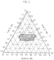
- a numerical range of an alloy containing greater than or equal to 29% by mass of silicon (Si) and containing tin (Sn) and carbon (C) is included in the area indicated by reference sign A shown in FIG. 1 .
- This negative electrode active material for a battery is used in a negative electrode for a battery, typically for a lithium ion secondary battery.
- the alloy contained in the negative electrode active material for a battery absorbs lithium ions when the battery is charged and releases the lithium ions when the battery is discharged.
- the negative electrode active material for a battery according to the embodiment of the present invention is a silicon series active material, to which Sn as a first additive element and C as a second additive element are added.
- Sn selected as a first additive element and C selected as a second additive element can suppress amorphous-crystal phase transition when being alloyed with Li so as to extend cycle life.
- such a negative electrode active material can ensure a higher capacity compared with conventional negative electrode active materials, for example, carbon series negative electrode active materials.
- the composition ranges of Sn and C as the first and second additive elements optimally determined contributes to providing the negative electrode active material containing the Si series alloy capable of exhibiting better cycle life after 50 cycles and even after 100 cycles.
- the cycle durability decreases and the capacity retention of greater than or equal to 45% after 100 cycles may not be ensured.
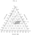
- the composition includes Si in the range from 29% by mass to 63% by mass, Sn in the range from 14% by mass to 48% by mass, and C in the range from 11% by mass to 48% by mass. These composition ranges contribute to ensuring a discharge capacity retention of greater than or equal to 92% after 50 cycles and a discharge capacity retention of greater than or equal to 45% after 100 cycles. These numerical ranges are included in the area indicated by reference sign B shown in FIG. 2 .
- the composition preferably includes Si in the range from 29% by mass to 44% by mass, Sn in the range from 14% by mass to 48% by mass, and C in the range from 11% by mass to 48% by mass. These composition ranges contribute to improving the cycle durability and ensuring a discharge capacity retention of greater than or equal to 50% after 100 cycles. These numerical ranges are included in the area indicated by reference sign C shown in FIG. 3 .
- the composition more preferably includes Si in the range from 29% by mass to 40% by mass and Sn in the range from 34% by mass to 48% by mass (namely, 12% by mass ⁇ C ⁇ 37% by mass). These composition ranges contribute to further improving the cycle durability and ensuring a discharge capacity retention of greater than or equal to 96% after 50 cycles and a discharge capacity retention of greater than or equal to 55% after 100 cycles. These numerical ranges are included in the area indicated by reference sign D shown in FIG. 4 .
- the negative electrode active material according to the embodiment of the present invention inevitably contains impurities derived from the raw materials and the production method, in addition to the three elements described above.
- the content of the inevitable impurities is preferably less than 0.5% by mass, more preferably less than 0.1 % by mass.
- the alloy contained in the negative electrode active material according to the present embodiment consists of silicon in a range from 29% by mass to 63% by mass inclusive, tin in a range from 14% by mass to 48% by mass inclusive, carbon in a range from 11% by mass to 48% by mass inclusive and inevitable impurities as a residue, wherein in the alloy elements Si, Sn and C and the inevitable impurities add up to 100% by mass.
- a method for manufacturing the negative electrode active material according to the embodiment of the present invention which is the Si-Sn-C series alloy having the above-described composition, is not particularly limited, and conventionally known various methods may be employed. Namely, any conventional manufacturing methods may be used without any particular obstacle, since there is little difference in the conditions and characteristics of the alloy depending on the manufacturing methods. For example, a multi PVD method (a sputtering method, a resistance heating method and a laser ablation method) or a multi CVD method (a chemical vapor-phase growth method) may be used to obtain an alloy in a thin film state having the composition described above.
- a multi PVD method a sputtering method, a resistance heating method and a laser ablation method
- a multi CVD method a chemical vapor-phase growth method
- Such an alloyed thin film can be directly formed on (applied to) a current collector so as to obtain a negative electrode and therefore has the advantage of simplification of the manufacturing process.
- the alloyed thin film need not use other components, such as a binder and an electric conducting additive, composing a negative electrode active material layer other than the alloy (the negative electrode active material). Therefore, the alloyed thin film as the negative electrode active material can simply be used for the negative electrode. Accordingly, the alloyed thin film also has the advantage of ensuring a high capacity and high energy density which satisfy the level suitable for practical use in vehicles.
- the alloyed thin film is suitable for analysis of the electrochemical characteristics of the active material.
- the alloyed thin film may be manufactured by use of a multi DC magnetron sputtering apparatus, such as an independently controllable ternary DC magnetron sputtering apparatus.
- This apparatus may freely form Si-Sn-C series alloyed thin films having various alloy constitutions and thicknesses on the surface of the substrate (the current collector).
- ternary series alloy samples having various constitutions can be obtained in such a manner as to use target 1 (Si), target 2 (Sn) and target 3 (C), fix the sputtering time, and change the power level of the DC power source to 185 W for Si, in the range from 0 W to 35 W for Sn, and in the range from 0 W to 180 W for C. It should be noted that, since sputtering conditions depend on sputtering devices, it is preferable to estimate appropriate ranges of the sputtering conditions through preliminary tests for each sputtering device.
- the negative electrode active material layer can use the Si-Sn-C series alloyed thin film.
- the negative electrode active material layer may be a layer containing particles of the Si-Sn-C series alloy as a main component.
- An example of a method for manufacturing the alloy in a particle state may be a mechanical alloying method or a roll rapid cooling method after arc plasma melting.
- the alloy in the particle state is used as the negative electrode active material
- slurry is prepared first in a manner such that a binder, an electric conducting additive and a viscosity control solvent are added to the alloy particles.
- the slurry thus obtained is then applied to the current collector to form the negative electrode active material layer so as to obtain the negative electrode.
- Such a process is superior in terms of mass production and practicality for actual battery electrodes.
- the average particle diameter of the particles is not particularly limited as long as it is substantially the same as that employed in conventional negative electrode active materials.
- the average particle diameter is preferably in the range from 1 ⁇ m to 20 ⁇ m.
- the average particle diameter is not limited thereto and does not necessarily fall within this range as long as it can effectively achieve the effects according to the embodiment of the present invention.
- the particle diameter represents the greatest length between any two points on the circumference of the active material particle (the observed plane) observed by observation means such as a scanning electron microscope (SEM) or a transmission electron microscope (TEM).
- the average particle diameter represents a value calculated with SEM or TEM as an average value of particle diameters of the particles observed in several to several tens of fields of view. Particle diameters and average particle diameters of other constituents may be determined in the same manner.
- a negative electrode for a battery according to an embodiment of the present invention includes the negative electrode active material containing the Si-Sn-C series alloy described above.
- Representative examples of the battery include a lithium ion secondary battery and an electrical double layer capacitor.
- the lithium ion secondary battery generally has a configuration, as shown in FIG. 5 , in which positive electrodes 11 and negative electrodes 12 are connected via electrolyte layers 13, each positive electrode 11 having a configuration in which a positive electrode active material and the like is applied to a positive electrode current collector, each negative electrode 12 having a configuration in which a negative electrode active material and the like is applied to a negative electrode current collector.
- the positive electrodes 11, the electrolyte layers 13 and the negative electrodes 12 are housed in a battery case. The respective components of the lithium ion secondary battery and the materials used therein are explained in detail below.
- the positive electrode 11 in the lithium ion secondary battery 1 has a configuration in which positive electrode active material layers 11 b are formed on both surfaces of a positive electrode current collector 11 a.
- the positive electrode current collector 11 a preferably contains an electrically conductive material such as aluminum foil, copper foil, nickel foil or stainless foil.
- the thickness of the positive electrode current collector 11a is not particularly limited but is generally preferably in the range from 1 ⁇ m to 30 ⁇ m.
- the positive electrode active material layer 11 b contains an electric conducting additive and a binder as necessary together with the positive electrode active material.
- the content ratio of the positive electrode active material, the electric conducting additive and the binder in the positive electrode active material layer 11 b is not particularly limited.
- Examples of the positive electrode active material include a lithium-transition metal composite oxide, a lithium-transition metal phosphate compound, a lithium-transition metal sulfated compound, a solid solution series material, a ternary series material, a NiMn series material, a NiCo series material, and a spinel manganese series material.
- lithium-transition metal composite oxide examples include LiMn 2 O 4 , LiCoO 2 , LiNiO 2 , Li(Ni, Mn, Co)O 2 , Li(Li, Ni, Mn, Co)O 2 , LiFePO 4 , and an oxide in which part of the transition metal contained in each of these composite oxides is replaced with other elements.
- An example of the lithium-transition metal phosphate compound may be LiFePO 4 .
- An example of the lithium-transition metal sulfated compound may be Li x Fe 2 (SO 4 ) 3 .
- the solid solution series material examples include xLiMO 2 ⁇ (1-x)Li 2 NO 3 (where 0 ⁇ x ⁇ 1, M represents at least one transition metal in an average oxidation state of 3+, and N represents at least one transition metal in an average oxidation state of 4+), and LiRO 2 -LiMn 2 O 4 (where R represents a transition metal element such as Ni, Mn, Co and Fe).
- the ternary series material may be a nickel-cobalt-manganese composite positive electrode material.
- the spinel manganese series material may be LiMn 2 O 4 .
- the NiMn series material may be LiNi 0.5 Mn 1.5 O 4 .
- the NiCo series material may be Li(NiCo)O 2 .
- Two or more kinds of the positive electrode active materials may be combined together according to circumstances. In view of a high capacity and output performance, the lithium-transition metal composite oxide is preferably used for the positive electrode active material.
- the particle diameter of the positive electrode active material is not particularly limited; however, it is generally preferably as small as possible. In view of operation efficiency and ease of handling, the average particle diameter may be approximately in the range from 1 ⁇ m to 30 ⁇ m, preferably approximately in the range from 5 ⁇ m to 20 ⁇ m. Other positive electrode active materials having different particle diameters may be used. In the case that the active materials require different particle diameters in order to achieve their own appropriate effects, the active materials having different particle diameters may be selected and mixed together so as to optimally function to achieve their own effects. Thus, it is not necessary to equalize the particle diameter of all of the active materials.
- the binder in the positive electrode active material layer 11 b is added to bind the active materials to each other or bind the active material to the positive electrode current collector 11a to maintain the electrode structure.
- the binder may be thermoplastic resin such as polyvinylidene fluoride (PVDF), polytetrafluoroethylene (PTFE), polyvinyl acetate, polyimide (PI), polyamide (PA), polyvinyl chloride (PVC), polymethyl acrylate (PMA), polymethyl methacrylate (PMMA), polyether nitrile (PEN), polyethylene (PE), polypropylene (PP), and polyacrylonitrile (PAN).
- the binder may be thermosetting resin such as epoxy resin, polyurethane resin, and urea resin, or a rubber material such as styrenebutadiene rubber (SBR).
- the electric conducting additive in the positive electrode active material layer 11 b is also referred to as an electric conducting agent added to improve electric conductivity.
- the electric conducting additive used in the embodiment of the present invention is not particularly limited, and a conventionally known agent may be used.
- the electric conducting additive may be a carbon material such as carbon black (such as acetylene black), graphite, and carbon fiber.
- the addition of the electric conducting additive contributes to effectively establishing an electronic network in the active material layer so as to improve output performance and battery reliability in association with an improvement in retention of an electrolysis solution.
- the negative electrode 12 has a configuration, as in the case of the positive electrode 11, in which negative electrode active material layers 12b are formed on both surfaces of a negative electrode current collector 12a containing an electrically conductive material.
- the negative electrode current collector 12a preferably contains, as in the case of the positive electrode current collector 11 a, an electrically conductive material such as aluminum foil, copper foil, nickel foil or stainless foil.
- the thickness of the negative electrode current collector 12a is preferably approximately in the range from 1 ⁇ m to 30 ⁇ m, as in the case of the positive electrode current collector 11 a.
- the negative electrode active material according to the present embodiment contains the Si-Sn-C series alloy having the above-described composition as an essential component.
- the negative electrode active material layer 12b according to the present embodiment may be a thin film including the Si-Sn-C series alloy as described above. In that case, the negative electrode active material layer may consist of the Si-Sn-C series alloy or may further contain a different negative electrode active material described below.
- the negative electrode active material layer 12b may be a layer containing the particles of the Si-Sn-C series alloy as a main component.
- the negative electrode active material layer 12b may contain the electric conducting additive and the binder as necessary, which the positive electrode active material layer 11 b may also contain.
- a main component represents a component contained in the negative electrode active material layer 12b with content of greater than or equal to 50% by mass.
- the lithium ion secondary battery as the battery according to the embodiment of the present invention includes the negative electrode active material including the Si-Sn-C series alloy having the above-described composition. Note that a conventionally known negative electrode active material capable of reversibly absorbing and releasing lithium may be used together without any particular obstacle as long as the negative electrode active material containing the above-described alloy is included as an essential component.
- the other negative electrode active material may be a carbon material such as graphite which is highly crystalline carbon (such as natural graphite and artificial graphite), low crystalline carbon (such as soft carbon and hard carbon), carbon black (such as Ketjenblack (registered trademark), acetylene black, channel black, lamp black, oil furnace black, and thermal black), fullerene, carbon nanotube, carbon nanofiber, carbon nanohorn, and carbon fibril.
- graphite which is highly crystalline carbon (such as natural graphite and artificial graphite), low crystalline carbon (such as soft carbon and hard carbon), carbon black (such as Ketjenblack (registered trademark), acetylene black, channel black, lamp black, oil furnace black, and thermal black), fullerene, carbon nanotube, carbon nanofiber, carbon nanohorn, and carbon fibril.
- the negative electrode active material may be a single substance alloyed with lithium such as Si, Ge, Sn, Pb, Al, In, Zn, H, Ca, Sr, Ba, Ru, Rh, Ir, Pd, Pt, Ag, Au, Cd, Hg, Ga, Tl, C, N, Sb, Bi, O, S, Se, Te, and Cl, or an oxide and a carbide containing these elements.
- the oxide may be silicon monoxide (SiO), SiO x (0 ⁇ x ⁇ 2), tin dioxide (SnO 2 ), SnO x (0 ⁇ x ⁇ 2), or SnSiO 3
- the carbide may be silicon carbide (SiC).
- Still another example of the negative electrode active material may be a metallic material such as lithium metal, or a lithium-transition metal composite oxide such as a lithium-titanium composite oxide (lithium titanate: Li 4 Ti 5 O 12 ).
- the negative electrode 12 may be obtained in a manner such that slurry containing the negative electrode active material together with the electric conducting additive and the binder, is applied to the surface of the negative electrode current collector 12a to form the negative electrode active material layer 12b.
- the negative electrode 12 may be obtained in a manner such that a thin film of the negative electrode active material alloy is directly formed on the surface of the negative electrode current collector 12a by a multi PVD method or a multi CVD method.
- the positive electrode active material layer and the negative electrode active material layer are each provided on one surface or both surfaces of the respective current collectors.
- one current collector may be provided with the positive electrode active material layer on one surface thereof and provided with the negative electrode active material layer on the other surface thereof. Electrodes having such a configuration are used for a bipolar battery.
- the electrolyte layer 13 contains a non-aqueous electrolyte, which serves as a carrier of lithium ions moving between the positive electrode and the negative electrode during charge and discharge.
- the thickness of the electrolyte layer 13 is preferably reduced as much as possible so as to decrease internal resistance, and is generally approximately in the range from 1 ⁇ m to 100 ⁇ m, preferably in the range from 5 ⁇ m to 50 ⁇ m.
- the non-aqueous electrolyte contained in the electrolyte layer 13 is not particularly limited as long as it functions as a carrier of lithium ions, and may be a liquid electrolyte or a polymer electrolyte.
- the liquid electrolyte has a constitution in which lithium salt (electrolyte salt) is dissolved in an organic solvent.
- the organic solvent may be carbonate such as ethylene carbonate (EC), propylene carbonate (PC), butylene carbonate (BC), vinylene carbonate (VC), dimethyl carbonate (DMC), diethyl carbonate (DEC), ethyl methyl carbonate (EMC), and methyl propyl carbonate (MPC).
- the lithium salt may be a compound that can be added to the electrode active material layers of the electrodes, such as Li(CF 3 SO 2 ) 2 N, Li(C 2 F 5 SO 2 ) 2 N, LiPF 6 , LiBF 4 , LiAsF 6 , LiTaF 6 , LiClO 4 , and LiCF 3 SO 3 .
- the polymer electrolyte is divided into two types; a gel polymer electrolyte (a gel electrolyte) containing an electrolysis solution, and an intrinsic polymer electrolyte not containing an electrolysis solution.
- the gel polymer electrolyte preferably has a constitution in which the liquid electrolyte is poured into a matrix polymer (a host polymer) including an ion conductive polymer.
- the use of the gel polymer electrolyte has the advantage of decreasing fluidity of the electrolyte so as to easily interrupt ion conduction between the respective layers.
- the ion conductive polymer used for the matrix polymer is not particularly limited. Examples thereof include polyethylene oxide (PEO), polypropylene oxide (PPO), polyvinylidene fluoride (PVDF), a copolymer of polyvinylidene fluoride and hexafluoropropylene (PVDF-HFP), polyethylene glycol (PEG), polyacrylonitrile (PAN), polymethyl methacrylate (PMMA), and a copolymer of these compounds.
- PEO polyethylene oxide
- PPO polypropylene oxide
- PVDF polyvinylidene fluoride
- PVDF-HFP copolymer of polyvinylidene fluoride and hexafluoropropylene
- PEG polyethylene glycol
- PAN polyacrylonitrile
- PMMA polymethyl methacrylate
- the ion conductive polymer may be the same as, or different from, an ion conductive polymer used as the electrolyte in the active material layers, but is preferably the same.
- the type of the electrolysis solution namely, the lithium salt and the organic solvent, is not particularly limited and may employ the electrolyte salt such as the lithium salt exemplified above and the organic solvent such as the carbonate exemplified above.
- the intrinsic polymer electrolyte has a constitution in which lithium salt is dissolved in the matrix polymer, but no organic solvent is contained.
- the use of the intrinsic polymer electrolyte contributes to reducing the risk of liquid leakage from the battery and thereby increasing reliability of the battery.
- the matrix polymer of the gel polymer electrolyte or the intrinsic polymer electrolyte can exhibit high mechanical strength when a cross-linked structure is formed.
- the cross-linked structure may be formed in a manner such that a polymerizable polymer used for polymer electrolyte formation (for example, PEO and PPO) is subjected to polymerization, such as thermal polymerization, ultraviolet polymerization, radiation polymerization, and electron beam polymerization, by use of an appropriate polymerization initiator.
- the non-aqueous electrolyte contained in the electrolyte layer 13 may be used singly, or two or more kinds thereof may be mixed together.
- a separator is preferably used in the electrolyte layer 13 when the electrolyte layer 13 contains the liquid electrolyte or the gel polymer electrolyte.
- the specific configuration of the separator may be a microporous film containing polyolefin such as polyethylene and polypropylene.
- the lithium ion secondary battery 1 has a configuration in which a battery constituent 10 to which a positive electrode tab 21 and a negative electrode tab 22 are attached, is sealed in an exterior body 30.
- the positive electrode tab 21 and the negative electrode tab 22 are exposed to the outside of the exterior body 30 on opposite sides.
- the positive electrode tab and the negative electrode tab may be exposed to the outside of the exterior body on the same side.
- the positive electrode tab and the negative electrode tab may be attached to the positive electrode current collectors 11a and the negative electrode current collectors 12a by, for example, ultrasonic welding or resistance welding.
- the positive electrode tab 21 and the negative electrode tab 22 are made of a material such as aluminum, copper, titanium, nickel, stainless steel (SUS), or an alloy thereof.
- the material is not limited thereto and may be any conventionally known material used for tabs for lithium ion secondary batteries.
- the positive electrode tab 21 and the negative electrode tab 22 may be made of the same material, or may be made of different materials.
- the tabs may be prepared preliminarily and then connected to the positive electrode current collectors 11a and the negative electrode current collectors 12a, which is the configuration according to the present embodiment.
- each of the positive electrode current collectors 11a and the negative electrode current collectors 12a may be elongated to serve as the respective tabs.
- each part of the positive electrode tab 21 and the negative electrode tab 22 exposed to the outside of the exterior body 30 is preferably covered with, for example, a heat shrinkable tube having a heat resistant and insulating property. This configuration decreases the chances of any negative influence on surrounding products (such as components in a vehicle, in particular, batteries) caused by a short circuit because of contact of the positive electrode tab 21 and the negative electrode tab 22 with peripheral devices or wires.
- current collecting plates may be used to extract and lead current to the outside of the battery. Such current collecting plates are electrically connected to the current collectors and leads and are exposed to the outside of the exterior body 30.
- the material constituting the current collecting plates is not particularly limited and may be a highly electrically conductive material conventionally used for current collecting plates for lithium ion secondary batteries.
- the constituent material of the current collecting plates is preferably a metallic material such as aluminum, copper, titanium, nickel, stainless steel (SUS), or an alloy thereof, particularly preferably aluminum or copper in view of lightness, corrosion resistance and high electric conductivity.
- the positive electrode current collecting plates and the negative electrode current collecting plates may be made of the same material, or may be made of different materials.
- the exterior body 30 is preferably made of a film-like exterior material in view of, for example, a reduction in size and weight.
- the exterior body 30 is not limited thereto and may be a conventionally known material used for exterior bodies for lithium ion secondary batteries. Namely, a metal can casing may be used.
- a polymer-metal composite laminate sheet having high heat conductivity may be used since this sheet has higher output power and cooling performance and is therefore suitably used in a battery for a large device such as an electric vehicle or a hybrid electric vehicle.
- an exterior body made of an exterior material such as a laminate film having a three-layer structure in which PP, aluminum and nylon are laminated in this order, may be used.
- the lithium ion secondary battery includes the battery constituent 10 in which a plurality of battery elements (electrode structures) 14 each including the positive electrode and the negative electrode connected to each other via the electrolyte layer, are stacked on top of each other.
- the lithium ion secondary battery has a structure in which the battery constituent 10 is housed in a battery case such as a can body or a laminate container (a package body).
- the lithium ion secondary battery is divided into two types: a wound type battery having a structure in which positive electrodes 11, electrolyte layers 13 and negative electrodes 12 are wound, and a laminated type battery having a structure in which positive electrodes 11, electrolyte layers 13 and negative electrodes 12 are stacked.
- the battery shown in FIG. 5 and a bipolar battery have a laminated type structure.
- the battery is also referred to as a coin cell, a button battery or a laminated battery depending on the shape and structure of the battery case.
- a sputtering apparatus As a sputtering apparatus, an independently controllable ternary DC magnetron sputtering apparatus (manufactured by Yamato-Kiki Industrial Co., Ltd.; combinatorial sputter coating apparatus; gun-sample distance: about 100 mm) was used. Thin films of negative electrode active material alloys having various constitutions were each formed with this apparatus on a substrate (a current collector) made of nickel foil having a thickness of 20 ⁇ m using the following targets under the following film formation conditions. Thus, 34 negative electrode samples having the constitutions shown in Tables 1 and 2 were obtained.
- the Si target, the Sn target and the C target were used, the sputtering time was set to 10 minutes, and the power level of the DC power source was changed in each target so as to be set to the respective ranges described above. Then, the alloyed thin films in an amorphous state were each formed on the Ni substrate so as to obtain the negative electrode samples including the alloyed thin films having various constitutions. Tables 1, 2 and FIG. 1 show the constituent composition of the respective alloyed thin films.
- the DC power source 1 (the Si target) was set to 185 W
- the DC power source 2 (the Sn target) was set to 35 W
- the DC power source 3 (the C target) was set to 110 W.
- the DC power source 1 (the Si target) was set to 185 W
- the DC power source 2 (the Sn target) was set to 22 W
- the DC power source 3 (the C target) was set to 0 W.
- the DC power source 1 (the Si target) was set to 185 W
- the DC power source 2 (the Sn target) was set to 0 W
- the DC power source 3 (the C target) was set to 30 W.
- the obtained alloyed thin films were analyzed by use of the following analyzing method and analyzing device.
- Each negative electrode sample obtained as described above was placed to face the counter electrode (the positive electrode) made of lithium foil with a separator interposed therebetween, and an electrolysis solution was poured therein, so as to prepare a CR2032 type coin cell prescribed in IEC60086 for each example.
- the lithium foil used was lithium foil (manufactured by Honjo Metal Co., Ltd.) cut out in such a manner as to have a diameter of 15 mm and a thickness of 200 ⁇ m.
- the separator used was Celgard 2400 (manufactured by Celgard, LLC.).
- the electrolysis solution used was prepared in a manner such that LiPF 6 (lithium hexafluorophosphate) was dissolved, at a concentration of 1 M, into a mixed non-aqueous solvent in which ethylene carbonate (EC) and diethyl carbonate (DEC) were mixed in the volume ratio of 1:1.
- LiPF 6 lithium hexafluorophosphate
- the batteries obtained as described above were each subjected to the following charge-discharge test.
- a charge-discharge tester HJ0501SM8A, manufactured by Hokuto Denko Corporation
- PFU-3K manufactured by ESPEC Corp.
- Each battery was charged at 0.1 mA from 2 V to 10 mV in constant current/constant voltage mode during charge, that is, in the process of Li intercalation to the negative electrode to be subjected to evaluation.
- each battery was discharged at 0.1 mA from 10 mV to 2 V in constant current mode during discharge, that is, in the process of Li release from the negative electrode.
- the negative electrode active material for a battery includes the Si-Sn-C series ternary alloy having the composition described above.
- the battery typically the lithium ion secondary battery, employing this negative electrode active material can improve the cycle life of the battery and ensure a high capacity and high cycle durability.
- the present invention is industrially applicable.
Landscapes
- Chemical & Material Sciences (AREA)
- Engineering & Computer Science (AREA)
- Materials Engineering (AREA)
- Organic Chemistry (AREA)
- Chemical Kinetics & Catalysis (AREA)
- Mechanical Engineering (AREA)
- Metallurgy (AREA)
- General Chemical & Material Sciences (AREA)
- Electrochemistry (AREA)
- Manufacturing & Machinery (AREA)
- Inorganic Chemistry (AREA)
- Battery Electrode And Active Subsutance (AREA)
- Carbon And Carbon Compounds (AREA)
- Physical Vapour Deposition (AREA)
- Electric Double-Layer Capacitors Or The Like (AREA)
Claims (7)
- Matériau actif d'électrode négative pour une batterie, comprenant un alliage contenant du silicium, de l'étain et du carbone, caractérisé en ce que ledit alliage est constitué de silicium dans une plage allant de 29% en masse à 63% en masse inclus, d'étain dans une plage allant de 14 % en masse à 48% en masse inclus, du carbone dans une plage allant de 11% en masse à 48% en masse inclus et des impuretés inévitables en tant que résidu, où dans les éléments d'alliage Si, Sn et C et les impuretés inévitables s'élèvent à 100% en masse.
- Matériau actif d'électrode négative pour une batterie selon la revendication 1, dans lequel l'alliage contient une quantité inférieure ou égale à 44% en masse de silicium.
- Matériau actif d'électrode négative pour une batterie selon la revendication 2, dans lequel l'alliage contient une quantité inférieure ou égale à 40% en masse de silicium et supérieure ou égale à 34% en masse d'étain et supérieure à 12% en masse et inférieure à 37% en masse de carbone.
- Électrode négative (12) pour une batterie, comprenant le matériau actif d'électrode négative selon l'une quelconque des revendications 1 à 3.
- Batterie comprenant le matériau actif d'électrode négative selon l'une quelconque des revendications 1 à 3.
- Batterie comprenant l'électrode négative pour une batterie selon la revendication 4.
- Batterie selon la revendication 5 ou 6, dans laquelle la batterie est une batterie secondaire au lithium-ion (1).
Applications Claiming Priority (2)
| Application Number | Priority Date | Filing Date | Title |
|---|---|---|---|
| JP2011284660A JP5904364B2 (ja) | 2011-12-27 | 2011-12-27 | 電気デバイス用負極活物質 |
| PCT/JP2012/078601 WO2013099440A1 (fr) | 2011-12-27 | 2012-11-05 | Matière active d'électrode négative destinée à un dispositif électrique, électrode négative destinée à un dispositif électrique et dispositif électrique |
Publications (3)
| Publication Number | Publication Date |
|---|---|
| EP2800175A1 EP2800175A1 (fr) | 2014-11-05 |
| EP2800175A4 EP2800175A4 (fr) | 2015-04-22 |
| EP2800175B1 true EP2800175B1 (fr) | 2016-06-15 |
Family
ID=48696940
Family Applications (1)
| Application Number | Title | Priority Date | Filing Date |
|---|---|---|---|
| EP12863433.4A Active EP2800175B1 (fr) | 2011-12-27 | 2012-11-05 | Matière active d'électrode négative destinée à un dispositif électrique, électrode négative destinée à un dispositif électrique et dispositif électrique |
Country Status (6)
| Country | Link |
|---|---|
| US (1) | US10547053B2 (fr) |
| EP (1) | EP2800175B1 (fr) |
| JP (1) | JP5904364B2 (fr) |
| KR (1) | KR101630551B1 (fr) |
| CN (1) | CN104011909B (fr) |
| WO (1) | WO2013099440A1 (fr) |
Families Citing this family (8)
| Publication number | Priority date | Publication date | Assignee | Title |
|---|---|---|---|---|
| JP5751448B2 (ja) | 2011-05-25 | 2015-07-22 | 日産自動車株式会社 | リチウムイオン二次電池用負極活物質 |
| EP2924776B1 (fr) * | 2012-11-22 | 2018-05-09 | Nissan Motor Co., Ltd | Électrode négative pour dispositif électrique et dispositif électrique l'utilisant |
| KR101780133B1 (ko) * | 2012-11-22 | 2017-09-19 | 닛산 지도우샤 가부시키가이샤 | 전기 디바이스용 부극, 및 이것을 사용한 전기 디바이스 |
| KR20180031067A (ko) | 2012-11-22 | 2018-03-27 | 닛산 지도우샤 가부시키가이샤 | 전기 디바이스용 부극, 및 이것을 사용한 전기 디바이스 |
| WO2014080886A1 (fr) | 2012-11-22 | 2014-05-30 | 日産自動車株式会社 | Electrode négative pour dispositif électrique et dispositif électrique l'utilisant |
| CN105934847B (zh) | 2014-01-24 | 2019-11-05 | 日产自动车株式会社 | 电器件 |
| CN105934846B (zh) | 2014-01-24 | 2019-06-28 | 日产自动车株式会社 | 电器件 |
| EP3293802B1 (fr) * | 2015-09-14 | 2020-10-21 | Toyota Jidosha Kabushiki Kaisha | Procédé de fabrication d'un système de batterie à l'état solide |
Family Cites Families (14)
| Publication number | Priority date | Publication date | Assignee | Title |
|---|---|---|---|---|
| PT1033767E (pt) * | 1998-09-18 | 2010-07-13 | Canon Kk | MATERIAL DE ELECTRODO PARA PËLO NEGATIVO DE CéLULA SECUNDáRIA DE LTIO, ESTRUTURA DE ELéCTRODO QUE UTILIZA O REFERIDO MATERIAL DE ELéCTRODO, CéLULA SECUNDáRIA DE LTIO QUE UTILIZA A REFERIDA ESTRUTURA DE ELéCTRODO, E PROCESSO PARA FABRICAÃO DA REFER |
| US20060040182A1 (en) | 2003-03-26 | 2006-02-23 | Canon Kabushiki Kaisha | Electrode material for lithium secondary battery and electrode structure having the electrode material |
| JP4464173B2 (ja) * | 2003-03-26 | 2010-05-19 | キヤノン株式会社 | リチウム二次電池用の電極材料、該電極材料を有する電極構造体、及び該電極構造体を有する二次電池 |
| US7771876B2 (en) * | 2003-05-09 | 2010-08-10 | Sony Corporation | Anode active material method of manufacturing the same and nonaqueous electrolyte secondary battery using the same |
| JP4051686B2 (ja) | 2004-09-30 | 2008-02-27 | ソニー株式会社 | 負極活物質およびそれを用いた電池 |
| WO2007015508A1 (fr) * | 2005-08-02 | 2007-02-08 | Showa Denko K.K. | Alliage pour une électrode négative de batterie secondaire au lithium |
| JP2007149604A (ja) * | 2005-11-30 | 2007-06-14 | Sanyo Electric Co Ltd | リチウム二次電池用負極及びリチウム二次電池 |
| US7906238B2 (en) * | 2005-12-23 | 2011-03-15 | 3M Innovative Properties Company | Silicon-containing alloys useful as electrodes for lithium-ion batteries |
| JP2008016446A (ja) * | 2006-06-09 | 2008-01-24 | Canon Inc | 粉末材料、粉末材料を用いた電極構造体及び該電極構造体を有する蓄電デバイス、並びに粉末材料の製造方法 |
| US8080335B2 (en) | 2006-06-09 | 2011-12-20 | Canon Kabushiki Kaisha | Powder material, electrode structure using the powder material, and energy storage device having the electrode structure |
| JP5109310B2 (ja) * | 2006-06-28 | 2012-12-26 | ソニー株式会社 | 電池 |
| US9012073B2 (en) * | 2008-11-11 | 2015-04-21 | Envia Systems, Inc. | Composite compositions, negative electrodes with composite compositions and corresponding batteries |
| EP2239803A1 (fr) * | 2009-04-10 | 2010-10-13 | Saft Groupe Sa | Composition de matiere active pour electrode negative d'accumulateur lithium-ion. |
| KR20140083009A (ko) * | 2011-10-10 | 2014-07-03 | 쓰리엠 이노베이티브 프로퍼티즈 컴파니 | 리튬-이온 전기화학 전지용 비정질 합금 음극 조성물 |
-
2011
- 2011-12-27 JP JP2011284660A patent/JP5904364B2/ja active Active
-
2012
- 2012-11-05 EP EP12863433.4A patent/EP2800175B1/fr active Active
- 2012-11-05 US US14/368,578 patent/US10547053B2/en active Active
- 2012-11-05 KR KR1020147019937A patent/KR101630551B1/ko not_active Expired - Fee Related
- 2012-11-05 CN CN201280064240.7A patent/CN104011909B/zh active Active
- 2012-11-05 WO PCT/JP2012/078601 patent/WO2013099440A1/fr not_active Ceased
Also Published As
| Publication number | Publication date |
|---|---|
| CN104011909B (zh) | 2016-09-28 |
| WO2013099440A1 (fr) | 2013-07-04 |
| EP2800175A4 (fr) | 2015-04-22 |
| JP5904364B2 (ja) | 2016-04-13 |
| US20140374666A1 (en) | 2014-12-25 |
| EP2800175A1 (fr) | 2014-11-05 |
| US10547053B2 (en) | 2020-01-28 |
| JP2013134906A (ja) | 2013-07-08 |
| KR101630551B1 (ko) | 2016-06-14 |
| KR20140115317A (ko) | 2014-09-30 |
| CN104011909A (zh) | 2014-08-27 |
Similar Documents
| Publication | Publication Date | Title |
|---|---|---|
| EP2800176B1 (fr) | Matière active d'électrode négative destinée à un dispositif électrique | |
| EP2685531B1 (fr) | Matériau actif d'électrode négative pour dispositifs électriques | |
| EP2685530B1 (fr) | Matériau actif d'électrode négative pour dispositif électrique et dispositif électrique | |
| EP2717357B1 (fr) | Matériau actif d'électrode négative pour dispositif électrique, électrode négative pour dispositif électrique et dispositif électrique | |
| EP2717358B1 (fr) | Matériau actif d'électrode négative pour dispositifs électriques | |
| EP2717355B1 (fr) | Matériau actif d'électrode négative pour dispositifs électriques | |
| EP2800175B1 (fr) | Matière active d'électrode négative destinée à un dispositif électrique, électrode négative destinée à un dispositif électrique et dispositif électrique | |
| EP2793301B1 (fr) | Matériau actif d'électrode négative pour dispositif électrique | |
| EP2717356B1 (fr) | Matériau actif d'électrode négative pour dispositifs électriques |
Legal Events
| Date | Code | Title | Description |
|---|---|---|---|
| PUAI | Public reference made under article 153(3) epc to a published international application that has entered the european phase |
Free format text: ORIGINAL CODE: 0009012 |
|
| 17P | Request for examination filed |
Effective date: 20140707 |
|
| AK | Designated contracting states |
Kind code of ref document: A1 Designated state(s): AL AT BE BG CH CY CZ DE DK EE ES FI FR GB GR HR HU IE IS IT LI LT LU LV MC MK MT NL NO PL PT RO RS SE SI SK SM TR |
|
| DAX | Request for extension of the european patent (deleted) | ||
| RA4 | Supplementary search report drawn up and despatched (corrected) |
Effective date: 20150319 |
|
| RIC1 | Information provided on ipc code assigned before grant |
Ipc: H01M 4/04 20060101ALN20150313BHEP Ipc: C23C 14/14 20060101ALI20150313BHEP Ipc: C23C 14/06 20060101ALI20150313BHEP Ipc: C01B 31/30 20060101ALI20150313BHEP Ipc: H01M 4/38 20060101AFI20150313BHEP Ipc: H01M 4/02 20060101ALN20150313BHEP Ipc: C22C 30/04 20060101ALI20150313BHEP Ipc: C23C 14/34 20060101ALI20150313BHEP Ipc: H01M 10/0525 20100101ALN20150313BHEP Ipc: C22C 13/00 20060101ALI20150313BHEP |
|
| 17Q | First examination report despatched |
Effective date: 20151002 |
|
| RIC1 | Information provided on ipc code assigned before grant |
Ipc: C23C 14/14 20060101ALI20151125BHEP Ipc: H01M 4/02 20060101ALN20151125BHEP Ipc: H01M 4/38 20060101AFI20151125BHEP Ipc: C23C 14/06 20060101ALI20151125BHEP Ipc: C23C 14/34 20060101ALI20151125BHEP Ipc: C22C 13/00 20060101ALI20151125BHEP Ipc: H01M 4/04 20060101ALN20151125BHEP Ipc: C22C 30/04 20060101ALI20151125BHEP |
|
| GRAP | Despatch of communication of intention to grant a patent |
Free format text: ORIGINAL CODE: EPIDOSNIGR1 |
|
| INTG | Intention to grant announced |
Effective date: 20160112 |
|
| RIN1 | Information on inventor provided before grant (corrected) |
Inventor name: TANAKA, OSAMU Inventor name: YOSHIDA, MASAO Inventor name: WATANABE, MANABU |
|
| GRAS | Grant fee paid |
Free format text: ORIGINAL CODE: EPIDOSNIGR3 |
|
| GRAA | (expected) grant |
Free format text: ORIGINAL CODE: 0009210 |
|
| AK | Designated contracting states |
Kind code of ref document: B1 Designated state(s): AL AT BE BG CH CY CZ DE DK EE ES FI FR GB GR HR HU IE IS IT LI LT LU LV MC MK MT NL NO PL PT RO RS SE SI SK SM TR |
|
| REG | Reference to a national code |
Ref country code: CH Ref legal event code: EP Ref country code: GB Ref legal event code: FG4D |
|
| REG | Reference to a national code |
Ref country code: IE Ref legal event code: FG4D |
|
| REG | Reference to a national code |
Ref country code: AT Ref legal event code: REF Ref document number: 806894 Country of ref document: AT Kind code of ref document: T Effective date: 20160715 |
|
| REG | Reference to a national code |
Ref country code: DE Ref legal event code: R096 Ref document number: 602012019647 Country of ref document: DE |
|
| REG | Reference to a national code |
Ref country code: LT Ref legal event code: MG4D |
|
| REG | Reference to a national code |
Ref country code: NL Ref legal event code: MP Effective date: 20160615 |
|
| PG25 | Lapsed in a contracting state [announced via postgrant information from national office to epo] |
Ref country code: NO Free format text: LAPSE BECAUSE OF FAILURE TO SUBMIT A TRANSLATION OF THE DESCRIPTION OR TO PAY THE FEE WITHIN THE PRESCRIBED TIME-LIMIT Effective date: 20160915 Ref country code: LT Free format text: LAPSE BECAUSE OF FAILURE TO SUBMIT A TRANSLATION OF THE DESCRIPTION OR TO PAY THE FEE WITHIN THE PRESCRIBED TIME-LIMIT Effective date: 20160615 Ref country code: FI Free format text: LAPSE BECAUSE OF FAILURE TO SUBMIT A TRANSLATION OF THE DESCRIPTION OR TO PAY THE FEE WITHIN THE PRESCRIBED TIME-LIMIT Effective date: 20160615 |
|
| REG | Reference to a national code |
Ref country code: AT Ref legal event code: MK05 Ref document number: 806894 Country of ref document: AT Kind code of ref document: T Effective date: 20160615 |
|
| REG | Reference to a national code |
Ref country code: FR Ref legal event code: PLFP Year of fee payment: 5 |
|
| PG25 | Lapsed in a contracting state [announced via postgrant information from national office to epo] |
Ref country code: GR Free format text: LAPSE BECAUSE OF FAILURE TO SUBMIT A TRANSLATION OF THE DESCRIPTION OR TO PAY THE FEE WITHIN THE PRESCRIBED TIME-LIMIT Effective date: 20160916 Ref country code: HR Free format text: LAPSE BECAUSE OF FAILURE TO SUBMIT A TRANSLATION OF THE DESCRIPTION OR TO PAY THE FEE WITHIN THE PRESCRIBED TIME-LIMIT Effective date: 20160615 Ref country code: NL Free format text: LAPSE BECAUSE OF FAILURE TO SUBMIT A TRANSLATION OF THE DESCRIPTION OR TO PAY THE FEE WITHIN THE PRESCRIBED TIME-LIMIT Effective date: 20160615 Ref country code: RS Free format text: LAPSE BECAUSE OF FAILURE TO SUBMIT A TRANSLATION OF THE DESCRIPTION OR TO PAY THE FEE WITHIN THE PRESCRIBED TIME-LIMIT Effective date: 20160615 Ref country code: LV Free format text: LAPSE BECAUSE OF FAILURE TO SUBMIT A TRANSLATION OF THE DESCRIPTION OR TO PAY THE FEE WITHIN THE PRESCRIBED TIME-LIMIT Effective date: 20160615 Ref country code: SE Free format text: LAPSE BECAUSE OF FAILURE TO SUBMIT A TRANSLATION OF THE DESCRIPTION OR TO PAY THE FEE WITHIN THE PRESCRIBED TIME-LIMIT Effective date: 20160615 |
|
| PG25 | Lapsed in a contracting state [announced via postgrant information from national office to epo] |
Ref country code: EE Free format text: LAPSE BECAUSE OF FAILURE TO SUBMIT A TRANSLATION OF THE DESCRIPTION OR TO PAY THE FEE WITHIN THE PRESCRIBED TIME-LIMIT Effective date: 20160615 Ref country code: IT Free format text: LAPSE BECAUSE OF FAILURE TO SUBMIT A TRANSLATION OF THE DESCRIPTION OR TO PAY THE FEE WITHIN THE PRESCRIBED TIME-LIMIT Effective date: 20160615 Ref country code: RO Free format text: LAPSE BECAUSE OF FAILURE TO SUBMIT A TRANSLATION OF THE DESCRIPTION OR TO PAY THE FEE WITHIN THE PRESCRIBED TIME-LIMIT Effective date: 20160615 Ref country code: SK Free format text: LAPSE BECAUSE OF FAILURE TO SUBMIT A TRANSLATION OF THE DESCRIPTION OR TO PAY THE FEE WITHIN THE PRESCRIBED TIME-LIMIT Effective date: 20160615 Ref country code: CZ Free format text: LAPSE BECAUSE OF FAILURE TO SUBMIT A TRANSLATION OF THE DESCRIPTION OR TO PAY THE FEE WITHIN THE PRESCRIBED TIME-LIMIT Effective date: 20160615 Ref country code: IS Free format text: LAPSE BECAUSE OF FAILURE TO SUBMIT A TRANSLATION OF THE DESCRIPTION OR TO PAY THE FEE WITHIN THE PRESCRIBED TIME-LIMIT Effective date: 20161015 |
|
| PG25 | Lapsed in a contracting state [announced via postgrant information from national office to epo] |
Ref country code: SM Free format text: LAPSE BECAUSE OF FAILURE TO SUBMIT A TRANSLATION OF THE DESCRIPTION OR TO PAY THE FEE WITHIN THE PRESCRIBED TIME-LIMIT Effective date: 20160615 Ref country code: PL Free format text: LAPSE BECAUSE OF FAILURE TO SUBMIT A TRANSLATION OF THE DESCRIPTION OR TO PAY THE FEE WITHIN THE PRESCRIBED TIME-LIMIT Effective date: 20160615 Ref country code: ES Free format text: LAPSE BECAUSE OF FAILURE TO SUBMIT A TRANSLATION OF THE DESCRIPTION OR TO PAY THE FEE WITHIN THE PRESCRIBED TIME-LIMIT Effective date: 20160615 Ref country code: AT Free format text: LAPSE BECAUSE OF FAILURE TO SUBMIT A TRANSLATION OF THE DESCRIPTION OR TO PAY THE FEE WITHIN THE PRESCRIBED TIME-LIMIT Effective date: 20160615 Ref country code: BE Free format text: LAPSE BECAUSE OF FAILURE TO SUBMIT A TRANSLATION OF THE DESCRIPTION OR TO PAY THE FEE WITHIN THE PRESCRIBED TIME-LIMIT Effective date: 20160615 Ref country code: PT Free format text: LAPSE BECAUSE OF FAILURE TO SUBMIT A TRANSLATION OF THE DESCRIPTION OR TO PAY THE FEE WITHIN THE PRESCRIBED TIME-LIMIT Effective date: 20161017 |
|
| REG | Reference to a national code |
Ref country code: DE Ref legal event code: R097 Ref document number: 602012019647 Country of ref document: DE |
|
| PLBE | No opposition filed within time limit |
Free format text: ORIGINAL CODE: 0009261 |
|
| STAA | Information on the status of an ep patent application or granted ep patent |
Free format text: STATUS: NO OPPOSITION FILED WITHIN TIME LIMIT |
|
| 26N | No opposition filed |
Effective date: 20170316 |
|
| PG25 | Lapsed in a contracting state [announced via postgrant information from national office to epo] |
Ref country code: DK Free format text: LAPSE BECAUSE OF FAILURE TO SUBMIT A TRANSLATION OF THE DESCRIPTION OR TO PAY THE FEE WITHIN THE PRESCRIBED TIME-LIMIT Effective date: 20160615 |
|
| REG | Reference to a national code |
Ref country code: CH Ref legal event code: PL |
|
| PG25 | Lapsed in a contracting state [announced via postgrant information from national office to epo] |
Ref country code: CH Free format text: LAPSE BECAUSE OF NON-PAYMENT OF DUE FEES Effective date: 20161130 Ref country code: LI Free format text: LAPSE BECAUSE OF NON-PAYMENT OF DUE FEES Effective date: 20161130 |
|
| REG | Reference to a national code |
Ref country code: IE Ref legal event code: MM4A |
|
| PG25 | Lapsed in a contracting state [announced via postgrant information from national office to epo] |
Ref country code: SI Free format text: LAPSE BECAUSE OF FAILURE TO SUBMIT A TRANSLATION OF THE DESCRIPTION OR TO PAY THE FEE WITHIN THE PRESCRIBED TIME-LIMIT Effective date: 20160615 |
|
| PG25 | Lapsed in a contracting state [announced via postgrant information from national office to epo] |
Ref country code: LU Free format text: LAPSE BECAUSE OF NON-PAYMENT OF DUE FEES Effective date: 20161130 |
|
| REG | Reference to a national code |
Ref country code: FR Ref legal event code: PLFP Year of fee payment: 6 |
|
| PG25 | Lapsed in a contracting state [announced via postgrant information from national office to epo] |
Ref country code: IE Free format text: LAPSE BECAUSE OF NON-PAYMENT OF DUE FEES Effective date: 20161105 |
|
| PG25 | Lapsed in a contracting state [announced via postgrant information from national office to epo] |
Ref country code: HU Free format text: LAPSE BECAUSE OF FAILURE TO SUBMIT A TRANSLATION OF THE DESCRIPTION OR TO PAY THE FEE WITHIN THE PRESCRIBED TIME-LIMIT; INVALID AB INITIO Effective date: 20121105 |
|
| PG25 | Lapsed in a contracting state [announced via postgrant information from national office to epo] |
Ref country code: CY Free format text: LAPSE BECAUSE OF FAILURE TO SUBMIT A TRANSLATION OF THE DESCRIPTION OR TO PAY THE FEE WITHIN THE PRESCRIBED TIME-LIMIT Effective date: 20160615 Ref country code: MK Free format text: LAPSE BECAUSE OF FAILURE TO SUBMIT A TRANSLATION OF THE DESCRIPTION OR TO PAY THE FEE WITHIN THE PRESCRIBED TIME-LIMIT Effective date: 20160615 Ref country code: MC Free format text: LAPSE BECAUSE OF FAILURE TO SUBMIT A TRANSLATION OF THE DESCRIPTION OR TO PAY THE FEE WITHIN THE PRESCRIBED TIME-LIMIT Effective date: 20160615 |
|
| PG25 | Lapsed in a contracting state [announced via postgrant information from national office to epo] |
Ref country code: BG Free format text: LAPSE BECAUSE OF FAILURE TO SUBMIT A TRANSLATION OF THE DESCRIPTION OR TO PAY THE FEE WITHIN THE PRESCRIBED TIME-LIMIT Effective date: 20160615 |
|
| PG25 | Lapsed in a contracting state [announced via postgrant information from national office to epo] |
Ref country code: MT Free format text: LAPSE BECAUSE OF NON-PAYMENT OF DUE FEES Effective date: 20161105 |
|
| REG | Reference to a national code |
Ref country code: FR Ref legal event code: PLFP Year of fee payment: 7 |
|
| PG25 | Lapsed in a contracting state [announced via postgrant information from national office to epo] |
Ref country code: AL Free format text: LAPSE BECAUSE OF FAILURE TO SUBMIT A TRANSLATION OF THE DESCRIPTION OR TO PAY THE FEE WITHIN THE PRESCRIBED TIME-LIMIT Effective date: 20160615 Ref country code: TR Free format text: LAPSE BECAUSE OF FAILURE TO SUBMIT A TRANSLATION OF THE DESCRIPTION OR TO PAY THE FEE WITHIN THE PRESCRIBED TIME-LIMIT Effective date: 20160615 |
|
| PGFP | Annual fee paid to national office [announced via postgrant information from national office to epo] |
Ref country code: DE Payment date: 20251022 Year of fee payment: 14 |
|
| PGFP | Annual fee paid to national office [announced via postgrant information from national office to epo] |
Ref country code: GB Payment date: 20251023 Year of fee payment: 14 |
|
| PGFP | Annual fee paid to national office [announced via postgrant information from national office to epo] |
Ref country code: FR Payment date: 20251022 Year of fee payment: 14 |