EP2800201A1 - Hochfrequenzfilter - Google Patents
Hochfrequenzfilter Download PDFInfo
- Publication number
- EP2800201A1 EP2800201A1 EP11879066.6A EP11879066A EP2800201A1 EP 2800201 A1 EP2800201 A1 EP 2800201A1 EP 11879066 A EP11879066 A EP 11879066A EP 2800201 A1 EP2800201 A1 EP 2800201A1
- Authority
- EP
- European Patent Office
- Prior art keywords
- intracavity
- conductor layer
- load
- source
- metal conductor
- Prior art date
- Legal status (The legal status is an assumption and is not a legal conclusion. Google has not performed a legal analysis and makes no representation as to the accuracy of the status listed.)
- Granted
Links
Images


Classifications
-
- H—ELECTRICITY
- H01—ELECTRIC ELEMENTS
- H01P—WAVEGUIDES; RESONATORS, LINES, OR OTHER DEVICES OF THE WAVEGUIDE TYPE
- H01P1/00—Auxiliary devices
- H01P1/20—Frequency-selective devices, e.g. filters
- H01P1/201—Filters for transverse electromagnetic waves
- H01P1/205—Comb or interdigital filters; Cascaded coaxial cavities
- H01P1/2053—Comb or interdigital filters; Cascaded coaxial cavities the coaxial cavity resonators being disposed parall to each other
-
- H—ELECTRICITY
- H01—ELECTRIC ELEMENTS
- H01P—WAVEGUIDES; RESONATORS, LINES, OR OTHER DEVICES OF THE WAVEGUIDE TYPE
- H01P7/00—Resonators of the waveguide type
- H01P7/04—Coaxial resonators
Definitions
- Embodiments of the present invention relate to the communication field, and in particular, to a high-frequency filter.
- a filter is widely used in the modem communication field, and a basic function is: making useful signals pass on a signal link to the greatest extent, and suppressing harmful signals to the greatest extent.
- existing high-frequency filters include micro-strip filters, strip line filters, and coaxial resonant cavity filters.
- a basic structural feature of a micro-strip filter is a base made of a dielectric material, where a metal conductor is laid on one surface of the base, and there is a grounded metal conductor layer at an opposite position on the other surface.
- a basic structural feature of a strip line filter is that a metal conductor is suspended or laid on a support made of a dielectric material, and metal conductors at corresponding positions on the top and bottom of the conductor form an outer conductor.
- a metal conductor is placed in an enclosed metal cavity of the filter, and both ends of the conductor are coupled with the metal cavity, where coupling strength and/or an electrical length of the metal conductor determines a resonant frequency.
- the coaxial resonant cavity filter provided in the prior art has a main feature that, the coaxial resonant cavity filter has many tuning structures.
- each coaxial resonant cavity has a screw for adjusting a frequency, and there is also a screw for adjusting coupling between one coaxial resonant cavity and another coaxial resonant cavity. Since these screws are associated with each other, the coaxial resonant cavity filter provided in the prior art cannot ensure consistency of indexes such as filter standing wave, phase, and group delay.
- Embodiments of the present invention provide a high-frequency filter, in order to ensure consistency of indexes of the filter.
- the embodiments of the present invention provide a high-frequency filter.
- the high-frequency filter includes: at least one coaxial resonant cavity, at least one printed circuit board arranged at the coaxial resonant cavity, and at least one intracavity conductor on a side of the printed circuit board.
- a metal conductor layer for performing signal connection for a source and a load is laid on a surface of the printed circuit board, and a grounded metal conductor layer is laid on the other surface opposite to the surface laid with the metal conductor layer.
- One end of the intracavity conductor and the coaxial resonant cavity are both grounded.
- the intracavity conductor and the metal conductor layer for performing signal connection for the source and the load are coupled.
- each coaxial resonant cavity of the high-frequency filter is provided with at least one printed circuit board and at least one intracavity conductor on a side of the printed circuit board. Since the printed circuit board has high machining precision, and can ensure batch consistency of indexes such as filter standing wave, phase, and group delay, a volume of the filter can be reduced in comparison to an air strip line because of a relatively high dielectric constant of the printed circuit board.
- a high-frequency filter provided in the embodiments of the present invention includes at least one coaxial resonant cavity, at least one printed circuit board (Printed Circuit Board, PCB) arranged at the coaxial resonant cavity, and at least one intracavity conductor on a side of the printed circuit board.
- One end of the intracavity conductor and the coaxial resonant cavity are both grounded.
- a metal conductor layer for performing signal connection for a source and a load is laid on a surface of the printed circuit board, and a grounded metal conductor layer is laid on the other surface opposite to the surface laid with the metal conductor layer for performing signal connection for the source and the load. Further, the intracavity conductor and the metal conductor layer for performing signal connection for the source and the load are coupled.
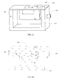
- FIG. 1a is a schematic structural diagram of a high-frequency filter provided in Embodiment 1 of the present invention.
- the high-frequency filter shown in FIG. 1a includes at least one grounded coaxial resonant cavity 101, at least one U-shaped coupling piece 103, at least one columnar intracavity conductor 104, and at least one printed circuit board 102 covering a cavity opening of the coaxial resonant cavity 101.
- FIG. 1b shows a schematic diagram of a structure and a relative position of each part of the coaxial resonant cavity of the high-frequency filter shown in FIG. 1a .
- a metal conductor layer 105 for performing signal connection for a source and a load is laid on a surface of the printed circuit board 102, and a grounded metal conductor layer is laid on the other surface opposite to the surface laid with the metal conductor layer 105 for performing signal connection for the source and the load.
- the grounded metal conductor layer may be laid on the whole surface, or the grounded metal conductor layer is at least laid on a portion contacting with the coaxial resonant cavity 101.
- the metal conductor layer 105 for performing signal connection for the source and the load may further has a function of coupling a signal connected by the metal conductor layer 105 to the columnar intracavity conductor 104.
- a screw 106 arranged on the columnar intracavity conductor 104 is configured to adjust a frequency.
- the columnar intracavity conductor 104 may be fixed on a cavity wall of the coaxial resonant cavity 101, and one end of the columnar intracavity conductor 104 contacts with a side wall of the coaxial resonant cavity 101 to implement grounding.
- An axial direction or a center line direction of the columnar intracavity conductor 104 is parallel to the surface of the printed circuit board 102 laid with the metal conductor layer 105 for performing signal connection for the source and the load or the surface laid with the grounded metal conductor layer.
- the columnar intracavity conductor 104 is a cylindrical intracavity conductor
- the axial direction of the columnar intracavity conductor 104 is parallel to the surface of the printed circuit board 102 laid with the metal conductor layer 105 for performing signal connection for the source and the load or the surface laid with the grounded metal conductor layer
- the columnar intracavity conductor 104 is a prismatic intracavity conductor
- the center line direction of the columnar intracavity conductor 104 is parallel to the surface of the printed circuit board 102 laid with the metal conductor layer 105 for performing signal connection for the source and the load or the surface laid with the grounded metal conductor layer.
- One end of the U-shaped coupling piece 103 is connected to the metal conductor layer 105, and the other end is connected to the grounded metal conductor layer.
- the function of the U-shaped coupling piece 103 is similar to that of an inductor.
- a magnetic field generated by the U-shaped coupling piece 103 excites a magnetic field of the coaxial resonant cavity 101.
- the columnar intracavity conductor 104 is coupled with the metal conductor layer 105 for performing signal connection for the source and the load via the magnetic field in the coaxial resonant cavity 101 excited by the U-shaped coupling piece 103, and this type of coupling is also called inductance coupling.
- a high-frequency filter provided in Embodiment 2 of the present invention includes at least one grounded coaxial resonant cavity, at least one printed circuit board covering a cavity opening of the coaxial resonant cavity, and at least one U-shaped intracavity conductor.
- FIG. 2a shows a schematic diagram of a structure and a relative position of each part in a coaxial resonant cavity 201 of the high-frequency filter provided in Embodiment 2.
- a metal conductor layer 204 for performing signal connection for a source and a load is laid on a surface of the printed circuit board 202, and a grounded metal conductor layer is laid on the other surface opposite to the surface laid with the metal conductor layer 204 for performing signal connection for the source and the load.
- the grounded metal conductor layer may be laid on the whole surface, or the grounded metal conductor layer is at least laid on a portion contacting with the coaxial resonant cavity 201.
- the metal conductor layer 204 for performing signal connection for the source and the load may further has a function of coupling a signal connected by the metal conductor layer 204 to a U-shaped intracavity conductor 203.
- the U-shaped intracavity conductor 203 may be curved prismatic or curved cylindrical.
- One end of the U-shaped intracavity conductor 203 contacts with the grounded metal conductor layer to implement grounding, and the other end is embedded in the printed circuit board 202, and does not contact with the metal conductor layer 204 for performing signal connection for the source and the load.
- a screw 205 arranged on the U-shaped intracavity conductor 203 is configured to adjust a frequency.
- the printed circuit board may further be arranged inside the coaxial resonant cavity 201, a cavity opening of the coaxial resonant cavity 201 may be shielded by using a shield plate, and the U-shaped intracavity conductor 203 may be curved cylindrical, as shown in FIG. 2b .
- One end of the U-shaped intracavity conductor 203 contacts with the grounded metal conductor layer laid on the printed circuit board 202, and the other end is embedded in the printed circuit board 202, but does not contact with the metal conductor layer 204 for performing signal connection for the source and the load.
- a horizontal portion of the U-shaped intracavity conductor 203 is parallel to the surface of the printed circuit board 202 laid with the metal conductor layer 204 for performing signal connection for the source and the load or the surface laid with the grounded metal conductor layer.
- the U-shaped intracavity conductor 203 may be coupled with the metal conductor layer 204 for performing signal connection for the source and the load by using the printed circuit board 202 as a medium, and this type of coupling is capacitance coupling.
- the structure and the relative position of each part in the coaxial resonant cavity may further be that: one end of the U-shaped intracavity conductor is connected to the grounded metal conductor layer, and the other end is embedded in the printed circuit board, and contacts with the metal conductor layer for performing signal connection for the source and the load.
- the horizontal portion of the U-shaped intracavity conductor is parallel to the surface of the printed circuit board laid with the metal conductor layer for performing signal connection for the source and the load or the surface laid with the grounded metal conductor layer.
- a high-frequency filter provided in Embodiment 3 of the present invention includes at least one grounded coaxial resonant cavity, at least one L-shaped intracavity conductor, and at least one printed circuit board covering a cavity opening of the coaxial resonant cavity.
- FIG. 3 shows a schematic diagram of a structure and a relative position of each part in a coaxial resonant cavity 301 of the high-frequency filter provided in Embodiment 3.
- a metal conductor layer 304 for performing signal connection for a source and a load is laid on a surface of a printed circuit board 302, and a grounded metal conductor layer is laid on the other surface opposite to the surface of the printed circuit board 302 laid with the metal conductor layer 304 for performing signal connection for the source and the load.
- the metal conductor layer 304 may further has a function of coupling a signal connected by the metal conductor layer 304 to an L-shaped intracavity conductor 303.
- the L-shaped intracavity conductor 303 may be curved prismatic or curved cylindrical, and a screw 305 on it is configured to adjust a frequency.
- One end of a vertical portion of the L-shaped intracavity conductor 303 is embedded in the printed circuit board 302, but does not contact with the metal conductor layer 304 for performing signal connection for the source and the load.
- the grounded metal conductor layer may be laid on the whole surface, or the grounded metal conductor layer is at least laid on a portion contacting with the coaxial resonant cavity 301. In this way, the coaxial resonant cavity 301 is also grounded.
- One end of a horizontal portion of the L-shaped intracavity conductor 303 contacts with a side wall of the coaxial resonant cavity 301. Since the coaxial resonant cavity 301 is grounded, the end of the horizontal portion of the L-shaped intracavity conductor 303 is equivalent to being grounded.
- the horizontal portion of the L-shaped intracavity conductor 303 is parallel to the surface of the printed circuit board 302 laid with the metal conductor layer 304 for performing signal connection for the source and the load or the surface laid with the grounded metal conductor layer.
- the L-shaped intracavity conductor 303 may be coupled with the metal conductor layer 304 for performing signal connection for the source and the load by using the printed circuit board 302 as a medium, and this type of coupling is capacitance coupling.
- the structure and the relative position of each part in the coaxial resonant cavity may further be that: the end of the vertical portion of the L-shaped intracavity conductor is embedded in the printed circuit board, and contacts with the metal conductor layer for performing signal connection for the source and the load.
- the grounded metal conductor layer may be laid on the whole surface, or the grounded metal conductor layer is laid on the portion contacting with the coaxial resonant cavity. In this way, the coaxial resonant cavity is also grounded.
- the end portion of the horizontal portion of the L-shaped intracavity conductor contacts with the side wall of the coaxial resonant cavity. Since the coaxial resonant cavity is grounded, the end portion of the horizontal portion of the L-shaped intracavity conductor is equivalent to be grounded.
- the horizontal portion of the L-shaped intracavity conductor is parallel to the surface of the printed circuit board laid with the metal conductor layer for performing signal connection for the source and the load or the surface laid with the grounded metal conductor layer.
- a high-frequency filter provided in Embodiment 4 of the present invention includes at least one grounded coaxial resonant cavity, at least one columnar intracavity conductor, at least one metal wire, and at least one printed circuit board covering a cavity opening of the coaxial resonant cavity.
- FIG. 4 shows a schematic diagram of a structure and a relative position of each part in a coaxial resonant cavity 401 of the high-frequency filter provided in Embodiment 4.
- a columnar intracavity conductor 402 may be a cylindrical intracavity conductor or a prismatic intracavity conductor.
- a metal conductor layer 404 for performing signal connection for a source and a load is laid on a surface of a printed circuit board 403, and a grounded metal conductor layer is laid on the other surface opposite to the surface laid with the metal conductor layer 404 for performing signal connection for the source and the load, or the grounded metal conductor layer is at least laid on a portion contacting with the coaxial resonant cavity 401.
- the coaxial resonant cavity 401 is also grounded.
- the metal conductor layer 404 for performing signal connection for the source and the load may further has a function of coupling a signal connected by the metal conductor layer 404 to the columnar intracavity conductor 402.
- the columnar intracavity conductor 402 may be fixed in the coaxial resonant cavity 401, and one end of the columnar intracavity conductor 402 contacts with a side wall of the coaxial resonant cavity 401 to implement grounding.
- a screw 407 arranged on the columnar intracavity conductor 402 is configured to adjust a frequency.
- the relative relation between the printed circuit board 403 and the columnar intracavity conductor 402 may be that: the surface of the printed circuit board 403 laid with the metal conductor layer 404 for performing signal connection for the source and the load or the surface laid with the grounded metal conductor layer is parallel to an axial direction or a center line direction of the columnar intracavity conductor 402.
- the columnar intracavity conductor 402 is a cylindrical intracavity conductor
- the surface of the printed circuit board 403 laid with the metal conductor layer 404 for performing signal connection for the source and the load or the surface laid with the grounded metal conductor layer is parallel to the axial direction of the columnar intracavity conductor 402; and if the columnar intracavity conductor 402 is a prismatic intracavity conductor, the surface of the printed circuit board 403 laid with the metal conductor layer 404 for performing signal connection for the source and the load or the surface laid with the grounded metal conductor layer is parallel to the center line direction of the columnar intracavity conductor 402.
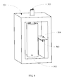
- a high-frequency filter provided in Embodiment 5 of the present invention includes at least one grounded coaxial resonant cavity, at least one columnar intracavity conductor, and at least one printed circuit board arranged inside the coaxial resonant cavity.
- FIG. 5 shows a schematic diagram of a structure and a relative position of each part in a coaxial resonant cavity 401 of the high-frequency filter provided in Embodiment 5.
- a metal conductor layer 504 for performing signal connection for a source and a load is laid on a surface of a printed circuit board 503, and a grounded metal conductor layer is laid on the surface opposite to the surface laid with the metal conductor layer 504 for performing signal connection for the source and the load.
- the grounded metal conductor layer contacts with a side wall of the coaxial resonant cavity.
- a columnar intracavity conductor 502 may be a cylindrical intracavity conductor or a prismatic intracavity conductor, and one end of it contacts with the coaxial resonant cavity 401.
- the metal conductor layer 504 for performing signal connection for the source and the load may further has a function of coupling a signal connected by the metal conductor layer 504 to the columnar intracavity conductor 502.
- a screw 505 arranged on the columnar intracavity conductor 502 is configured to adjust a frequency.
- the relative relation between the printed circuit board 503 and the columnar intracavity conductor 502 may be that: the surface of the printed circuit board 503 laid with the metal conductor layer 504 for performing signal connection for the source and the load or the surface laid with the grounded metal conductor layer 505 is perpendicular to an axial direction or a center line (if the columnar intracavity conductor 502 is a prismatic intracavity conductor) direction of the columnar intracavity conductor 502.
- the surface of the printed circuit board 503 laid with the metal conductor layer 504 for performing signal connection for the source and the load or the surface laid with the grounded metal conductor layer 505 is perpendicular to the axial direction of the columnar intracavity conductor 502; and if the columnar intracavity conductor 502 is a prismatic intracavity conductor, the surface of the printed circuit board 503 laid with the metal conductor layer 504 for performing signal connection for the source and the load or the surface laid with the grounded metal conductor layer 505 is perpendicular to the center line direction of the columnar intracavity conductor 502.
- each coaxial resonant cavity of the high-frequency filter is provided with at least one printed circuit board and at least one intracavity conductor on a side of the printed circuit board. Because the plate making craft can ensure dimensional precision of the metal conductor layer for performing signal connection for the source and the load within plus or minus 1 mil (milli-inch), a dimensional tolerance of the printed circuit board and a fluctuation range of the dielectric constant can be effectively controlled, and there is no assembly tolerance.
- This high consistency of the printed circuit board ensures that consistency of indexes of components of the printed circuit board structure is higher than that of components assembled through pure machining.
- the high consistency of the printed circuit board ensures batch consistency of indexes such as filter standing wave, phase, and group delay, and a volume of the filter can be reduced in comparison to an air strip line because of a relatively high dielectric constant of the printed circuit board.
Landscapes
- Physics & Mathematics (AREA)
- Electromagnetism (AREA)
- Control Of Motors That Do Not Use Commutators (AREA)
Applications Claiming Priority (1)
| Application Number | Priority Date | Filing Date | Title |
|---|---|---|---|
| PCT/CN2011/085003 WO2013097168A1 (zh) | 2011-12-30 | 2011-12-30 | 一种高频滤波器 |
Publications (3)
| Publication Number | Publication Date |
|---|---|
| EP2800201A1 true EP2800201A1 (de) | 2014-11-05 |
| EP2800201A4 EP2800201A4 (de) | 2015-04-22 |
| EP2800201B1 EP2800201B1 (de) | 2018-11-14 |
Family
ID=46995178
Family Applications (1)
| Application Number | Title | Priority Date | Filing Date |
|---|---|---|---|
| EP11879066.6A Active EP2800201B1 (de) | 2011-12-30 | 2011-12-30 | Hochfrequenzfilter |
Country Status (3)
| Country | Link |
|---|---|
| EP (1) | EP2800201B1 (de) |
| CN (1) | CN102742072B (de) |
| WO (1) | WO2013097168A1 (de) |
Cited By (3)
| Publication number | Priority date | Publication date | Assignee | Title |
|---|---|---|---|---|
| DE102016104608A1 (de) * | 2016-03-14 | 2017-09-14 | Kathrein-Werke Kg | Koaxialfilter in Rahmenbauweise |
| EP3240100A1 (de) * | 2016-04-28 | 2017-11-01 | Alcatel Lucent | Funkfrequenzfilter mit einer kammer und filtrierverfahren |
| US12040524B2 (en) | 2021-03-30 | 2024-07-16 | Nokia Solutions And Networks Oy | Cavity filter element for a cavity filter |
Families Citing this family (4)
| Publication number | Priority date | Publication date | Assignee | Title |
|---|---|---|---|---|
| CN110867634B (zh) * | 2018-08-28 | 2022-06-24 | 罗森伯格技术有限公司 | 一种电磁混合耦合滤波器 |
| CN109728388B (zh) * | 2019-02-12 | 2023-12-05 | 华南理工大学 | 一种具有恒定绝对带宽的高选择性电调同轴滤波器 |
| CN111584983B (zh) * | 2020-06-09 | 2021-07-13 | 中国电子科技集团公司第十四研究所 | 一种多层结构的滤波耦合组件 |
| CN117154409A (zh) * | 2020-10-27 | 2023-12-01 | 华为技术有限公司 | 一种传输线组件、天线组件和移动终端 |
Family Cites Families (11)
| Publication number | Priority date | Publication date | Assignee | Title |
|---|---|---|---|---|
| US5004993A (en) * | 1989-09-19 | 1991-04-02 | The United States Of America As Represented By The Secretary Of The Navy | Constricted split block waveguide low pass filter with printed circuit filter substrate |
| JP3379326B2 (ja) * | 1996-02-20 | 2003-02-24 | 三菱電機株式会社 | 高周波フィルタ |
| FI106584B (fi) * | 1997-02-07 | 2001-02-28 | Filtronic Lk Oy | Korkeataajuussuodatin |
| JP2001044704A (ja) * | 1999-07-29 | 2001-02-16 | Sony Corp | 分布定数回路素子とその製造方法およびプリント配線板 |
| US6919782B2 (en) * | 2001-04-04 | 2005-07-19 | Adc Telecommunications, Inc. | Filter structure including circuit board |
| CH696098A5 (de) * | 2002-12-11 | 2006-12-15 | Thales Suisse Sa | Abstimmbare Hochfrequenz-Filteranordnung sowie Verfahren zu ihrer Herstellung. |
| TWI301336B (en) * | 2003-12-24 | 2008-09-21 | Delta Electronics Inc | High frequency filter |
| FI119402B (fi) * | 2004-03-22 | 2008-10-31 | Filtronic Comtek Oy | Järjestely suodattimen lähtösignaalin jakamiseksi |
| US7592882B2 (en) * | 2007-02-22 | 2009-09-22 | John Mezzalingua Associates, Inc. | Dual bandstop filter with enhanced upper passband response |
| EP2056394B1 (de) * | 2007-10-31 | 2013-09-04 | Alcatel Lucent | Hohlraumresonator |
| CN101471477A (zh) * | 2007-12-27 | 2009-07-01 | 奥雷通光通讯设备(上海)有限公司 | 一种用于无源腔体滤波器的耦合器 |
-
2011
- 2011-12-30 WO PCT/CN2011/085003 patent/WO2013097168A1/zh not_active Ceased
- 2011-12-30 CN CN201180003585.7A patent/CN102742072B/zh active Active
- 2011-12-30 EP EP11879066.6A patent/EP2800201B1/de active Active
Cited By (4)
| Publication number | Priority date | Publication date | Assignee | Title |
|---|---|---|---|---|
| DE102016104608A1 (de) * | 2016-03-14 | 2017-09-14 | Kathrein-Werke Kg | Koaxialfilter in Rahmenbauweise |
| US10347958B2 (en) | 2016-03-14 | 2019-07-09 | Kathrein Se | Coaxial filter having a frame construction and a conductive separating web, where internal resonators can be galvanically connected to either the frame construction or the separating web |
| EP3240100A1 (de) * | 2016-04-28 | 2017-11-01 | Alcatel Lucent | Funkfrequenzfilter mit einer kammer und filtrierverfahren |
| US12040524B2 (en) | 2021-03-30 | 2024-07-16 | Nokia Solutions And Networks Oy | Cavity filter element for a cavity filter |
Also Published As
| Publication number | Publication date |
|---|---|
| CN102742072A (zh) | 2012-10-17 |
| EP2800201A4 (de) | 2015-04-22 |
| CN102742072B (zh) | 2014-07-30 |
| EP2800201B1 (de) | 2018-11-14 |
| WO2013097168A1 (zh) | 2013-07-04 |
Similar Documents
| Publication | Publication Date | Title |
|---|---|---|
| EP2800201A1 (de) | Hochfrequenzfilter | |
| JP6124085B2 (ja) | 無線電力伝送装置、無線電力送電装置および受電装置 | |
| KR102503237B1 (ko) | 무선 주파수 필터 | |
| JP6291699B2 (ja) | クロスカップリングを利用する空洞フィルタ | |
| US7499001B2 (en) | Dielectric antenna device | |
| CN107359394A (zh) | 可调电磁混合耦合滤波器 | |
| JP5457931B2 (ja) | 非導波管線路−導波管変換器及び非導波管線路−導波管変換器を用いた通信用装置 | |
| EP2347467A1 (de) | Übergang von hochfrequenz-koaxial zu streifenleitung/mikrostreifen | |
| US20140292438A1 (en) | Input/Output Structure For Dielectric Waveguide | |
| JPH09246820A (ja) | 誘電体共振器および帯域通過フィルタ | |
| EP1764858B1 (de) | Dielektrische Anordnung | |
| EP2325940A1 (de) | Mehrmoden-Resonanzvorrichtung | |
| CN120032978B (zh) | 一种电感及环形器 | |
| US9634367B2 (en) | Filter | |
| US9013252B1 (en) | Pedestal-based dielectric-loaded cavity resonator | |
| US9871280B2 (en) | Dielectric resonator, dielectric filter, and communication apparatus | |
| CN214477826U (zh) | 一种小型化低频腔体滤波器 | |
| JP6872771B2 (ja) | 共振器及びフィルタ | |
| JP3606274B2 (ja) | 誘電体共振器、誘電体フィルタ | |
| GB2570765A (en) | Resonator apparatus and method of use thereof | |
| JP2017022682A (ja) | ノイズフィルタ | |
| EP3226349B1 (de) | Antenne und endgerät | |
| CN104037479A (zh) | 腔体耦合结构 | |
| JP2003179403A (ja) | 誘電体ノッチフィルタ | |
| JP2003124717A (ja) | 誘電体共振器 |
Legal Events
| Date | Code | Title | Description |
|---|---|---|---|
| PUAI | Public reference made under article 153(3) epc to a published international application that has entered the european phase |
Free format text: ORIGINAL CODE: 0009012 |
|
| 17P | Request for examination filed |
Effective date: 20140729 |
|
| AK | Designated contracting states |
Kind code of ref document: A1 Designated state(s): AL AT BE BG CH CY CZ DE DK EE ES FI FR GB GR HR HU IE IS IT LI LT LU LV MC MK MT NL NO PL PT RO RS SE SI SK SM TR |
|
| RIC1 | Information provided on ipc code assigned before grant |
Ipc: H01P 7/04 20060101ALI20141124BHEP Ipc: H01P 1/205 20060101ALI20141124BHEP Ipc: H01P 1/203 20060101ALI20141124BHEP Ipc: H01P 7/10 20060101AFI20141124BHEP |
|
| DAX | Request for extension of the european patent (deleted) | ||
| RA4 | Supplementary search report drawn up and despatched (corrected) |
Effective date: 20150319 |
|
| RIC1 | Information provided on ipc code assigned before grant |
Ipc: H01P 1/203 20060101ALI20150313BHEP Ipc: H01P 1/205 20060101ALI20150313BHEP Ipc: H01P 7/04 20060101ALI20150313BHEP Ipc: H01P 7/10 20060101AFI20150313BHEP |
|
| 17Q | First examination report despatched |
Effective date: 20170705 |
|
| GRAP | Despatch of communication of intention to grant a patent |
Free format text: ORIGINAL CODE: EPIDOSNIGR1 |
|
| INTG | Intention to grant announced |
Effective date: 20180529 |
|
| GRAS | Grant fee paid |
Free format text: ORIGINAL CODE: EPIDOSNIGR3 |
|
| GRAA | (expected) grant |
Free format text: ORIGINAL CODE: 0009210 |
|
| AK | Designated contracting states |
Kind code of ref document: B1 Designated state(s): AL AT BE BG CH CY CZ DE DK EE ES FI FR GB GR HR HU IE IS IT LI LT LU LV MC MK MT NL NO PL PT RO RS SE SI SK SM TR |
|
| REG | Reference to a national code |
Ref country code: GB Ref legal event code: FG4D |
|
| REG | Reference to a national code |
Ref country code: CH Ref legal event code: EP Ref country code: AT Ref legal event code: REF Ref document number: 1065921 Country of ref document: AT Kind code of ref document: T Effective date: 20181115 |
|
| REG | Reference to a national code |
Ref country code: DE Ref legal event code: R096 Ref document number: 602011053991 Country of ref document: DE |
|
| REG | Reference to a national code |
Ref country code: IE Ref legal event code: FG4D |
|
| REG | Reference to a national code |
Ref country code: NL Ref legal event code: MP Effective date: 20181114 |
|
| REG | Reference to a national code |
Ref country code: LT Ref legal event code: MG4D |
|
| REG | Reference to a national code |
Ref country code: AT Ref legal event code: MK05 Ref document number: 1065921 Country of ref document: AT Kind code of ref document: T Effective date: 20181114 |
|
| PG25 | Lapsed in a contracting state [announced via postgrant information from national office to epo] |
Ref country code: IS Free format text: LAPSE BECAUSE OF FAILURE TO SUBMIT A TRANSLATION OF THE DESCRIPTION OR TO PAY THE FEE WITHIN THE PRESCRIBED TIME-LIMIT Effective date: 20190314 Ref country code: BG Free format text: LAPSE BECAUSE OF FAILURE TO SUBMIT A TRANSLATION OF THE DESCRIPTION OR TO PAY THE FEE WITHIN THE PRESCRIBED TIME-LIMIT Effective date: 20190214 Ref country code: LT Free format text: LAPSE BECAUSE OF FAILURE TO SUBMIT A TRANSLATION OF THE DESCRIPTION OR TO PAY THE FEE WITHIN THE PRESCRIBED TIME-LIMIT Effective date: 20181114 Ref country code: ES Free format text: LAPSE BECAUSE OF FAILURE TO SUBMIT A TRANSLATION OF THE DESCRIPTION OR TO PAY THE FEE WITHIN THE PRESCRIBED TIME-LIMIT Effective date: 20181114 Ref country code: AT Free format text: LAPSE BECAUSE OF FAILURE TO SUBMIT A TRANSLATION OF THE DESCRIPTION OR TO PAY THE FEE WITHIN THE PRESCRIBED TIME-LIMIT Effective date: 20181114 Ref country code: HR Free format text: LAPSE BECAUSE OF FAILURE TO SUBMIT A TRANSLATION OF THE DESCRIPTION OR TO PAY THE FEE WITHIN THE PRESCRIBED TIME-LIMIT Effective date: 20181114 Ref country code: NO Free format text: LAPSE BECAUSE OF FAILURE TO SUBMIT A TRANSLATION OF THE DESCRIPTION OR TO PAY THE FEE WITHIN THE PRESCRIBED TIME-LIMIT Effective date: 20190214 Ref country code: LV Free format text: LAPSE BECAUSE OF FAILURE TO SUBMIT A TRANSLATION OF THE DESCRIPTION OR TO PAY THE FEE WITHIN THE PRESCRIBED TIME-LIMIT Effective date: 20181114 Ref country code: FI Free format text: LAPSE BECAUSE OF FAILURE TO SUBMIT A TRANSLATION OF THE DESCRIPTION OR TO PAY THE FEE WITHIN THE PRESCRIBED TIME-LIMIT Effective date: 20181114 |
|
| PG25 | Lapsed in a contracting state [announced via postgrant information from national office to epo] |
Ref country code: AL Free format text: LAPSE BECAUSE OF FAILURE TO SUBMIT A TRANSLATION OF THE DESCRIPTION OR TO PAY THE FEE WITHIN THE PRESCRIBED TIME-LIMIT Effective date: 20181114 Ref country code: PT Free format text: LAPSE BECAUSE OF FAILURE TO SUBMIT A TRANSLATION OF THE DESCRIPTION OR TO PAY THE FEE WITHIN THE PRESCRIBED TIME-LIMIT Effective date: 20190314 Ref country code: SE Free format text: LAPSE BECAUSE OF FAILURE TO SUBMIT A TRANSLATION OF THE DESCRIPTION OR TO PAY THE FEE WITHIN THE PRESCRIBED TIME-LIMIT Effective date: 20181114 Ref country code: RS Free format text: LAPSE BECAUSE OF FAILURE TO SUBMIT A TRANSLATION OF THE DESCRIPTION OR TO PAY THE FEE WITHIN THE PRESCRIBED TIME-LIMIT Effective date: 20181114 Ref country code: GR Free format text: LAPSE BECAUSE OF FAILURE TO SUBMIT A TRANSLATION OF THE DESCRIPTION OR TO PAY THE FEE WITHIN THE PRESCRIBED TIME-LIMIT Effective date: 20190215 Ref country code: NL Free format text: LAPSE BECAUSE OF FAILURE TO SUBMIT A TRANSLATION OF THE DESCRIPTION OR TO PAY THE FEE WITHIN THE PRESCRIBED TIME-LIMIT Effective date: 20181114 |
|
| PG25 | Lapsed in a contracting state [announced via postgrant information from national office to epo] |
Ref country code: CZ Free format text: LAPSE BECAUSE OF FAILURE TO SUBMIT A TRANSLATION OF THE DESCRIPTION OR TO PAY THE FEE WITHIN THE PRESCRIBED TIME-LIMIT Effective date: 20181114 Ref country code: IT Free format text: LAPSE BECAUSE OF FAILURE TO SUBMIT A TRANSLATION OF THE DESCRIPTION OR TO PAY THE FEE WITHIN THE PRESCRIBED TIME-LIMIT Effective date: 20181114 Ref country code: DK Free format text: LAPSE BECAUSE OF FAILURE TO SUBMIT A TRANSLATION OF THE DESCRIPTION OR TO PAY THE FEE WITHIN THE PRESCRIBED TIME-LIMIT Effective date: 20181114 Ref country code: PL Free format text: LAPSE BECAUSE OF FAILURE TO SUBMIT A TRANSLATION OF THE DESCRIPTION OR TO PAY THE FEE WITHIN THE PRESCRIBED TIME-LIMIT Effective date: 20181114 |
|
| REG | Reference to a national code |
Ref country code: CH Ref legal event code: PL |
|
| REG | Reference to a national code |
Ref country code: DE Ref legal event code: R097 Ref document number: 602011053991 Country of ref document: DE |
|
| PG25 | Lapsed in a contracting state [announced via postgrant information from national office to epo] |
Ref country code: EE Free format text: LAPSE BECAUSE OF FAILURE TO SUBMIT A TRANSLATION OF THE DESCRIPTION OR TO PAY THE FEE WITHIN THE PRESCRIBED TIME-LIMIT Effective date: 20181114 Ref country code: SK Free format text: LAPSE BECAUSE OF FAILURE TO SUBMIT A TRANSLATION OF THE DESCRIPTION OR TO PAY THE FEE WITHIN THE PRESCRIBED TIME-LIMIT Effective date: 20181114 Ref country code: MC Free format text: LAPSE BECAUSE OF FAILURE TO SUBMIT A TRANSLATION OF THE DESCRIPTION OR TO PAY THE FEE WITHIN THE PRESCRIBED TIME-LIMIT Effective date: 20181114 Ref country code: LU Free format text: LAPSE BECAUSE OF NON-PAYMENT OF DUE FEES Effective date: 20181230 Ref country code: RO Free format text: LAPSE BECAUSE OF FAILURE TO SUBMIT A TRANSLATION OF THE DESCRIPTION OR TO PAY THE FEE WITHIN THE PRESCRIBED TIME-LIMIT Effective date: 20181114 Ref country code: SM Free format text: LAPSE BECAUSE OF FAILURE TO SUBMIT A TRANSLATION OF THE DESCRIPTION OR TO PAY THE FEE WITHIN THE PRESCRIBED TIME-LIMIT Effective date: 20181114 |
|
| PLBE | No opposition filed within time limit |
Free format text: ORIGINAL CODE: 0009261 |
|
| STAA | Information on the status of an ep patent application or granted ep patent |
Free format text: STATUS: NO OPPOSITION FILED WITHIN TIME LIMIT |
|
| REG | Reference to a national code |
Ref country code: BE Ref legal event code: MM Effective date: 20181231 Ref country code: IE Ref legal event code: MM4A |
|
| 26N | No opposition filed |
Effective date: 20190815 |
|
| GBPC | Gb: european patent ceased through non-payment of renewal fee |
Effective date: 20190214 |
|
| PG25 | Lapsed in a contracting state [announced via postgrant information from national office to epo] |
Ref country code: FR Free format text: LAPSE BECAUSE OF NON-PAYMENT OF DUE FEES Effective date: 20190114 Ref country code: IE Free format text: LAPSE BECAUSE OF NON-PAYMENT OF DUE FEES Effective date: 20181230 Ref country code: SI Free format text: LAPSE BECAUSE OF FAILURE TO SUBMIT A TRANSLATION OF THE DESCRIPTION OR TO PAY THE FEE WITHIN THE PRESCRIBED TIME-LIMIT Effective date: 20181114 |
|
| PG25 | Lapsed in a contracting state [announced via postgrant information from national office to epo] |
Ref country code: BE Free format text: LAPSE BECAUSE OF NON-PAYMENT OF DUE FEES Effective date: 20181231 |
|
| PG25 | Lapsed in a contracting state [announced via postgrant information from national office to epo] |
Ref country code: LI Free format text: LAPSE BECAUSE OF NON-PAYMENT OF DUE FEES Effective date: 20181231 Ref country code: CH Free format text: LAPSE BECAUSE OF NON-PAYMENT OF DUE FEES Effective date: 20181231 |
|
| PG25 | Lapsed in a contracting state [announced via postgrant information from national office to epo] |
Ref country code: GB Free format text: LAPSE BECAUSE OF NON-PAYMENT OF DUE FEES Effective date: 20190214 Ref country code: MT Free format text: LAPSE BECAUSE OF NON-PAYMENT OF DUE FEES Effective date: 20181230 |
|
| PG25 | Lapsed in a contracting state [announced via postgrant information from national office to epo] |
Ref country code: TR Free format text: LAPSE BECAUSE OF FAILURE TO SUBMIT A TRANSLATION OF THE DESCRIPTION OR TO PAY THE FEE WITHIN THE PRESCRIBED TIME-LIMIT Effective date: 20181114 |
|
| PG25 | Lapsed in a contracting state [announced via postgrant information from national office to epo] |
Ref country code: MK Free format text: LAPSE BECAUSE OF NON-PAYMENT OF DUE FEES Effective date: 20181114 Ref country code: CY Free format text: LAPSE BECAUSE OF FAILURE TO SUBMIT A TRANSLATION OF THE DESCRIPTION OR TO PAY THE FEE WITHIN THE PRESCRIBED TIME-LIMIT Effective date: 20181114 Ref country code: HU Free format text: LAPSE BECAUSE OF FAILURE TO SUBMIT A TRANSLATION OF THE DESCRIPTION OR TO PAY THE FEE WITHIN THE PRESCRIBED TIME-LIMIT; INVALID AB INITIO Effective date: 20111230 |
|
| PGFP | Annual fee paid to national office [announced via postgrant information from national office to epo] |
Ref country code: DE Payment date: 20251104 Year of fee payment: 15 |