EP2800247A1 - Moteur - Google Patents
Moteur Download PDFInfo
- Publication number
- EP2800247A1 EP2800247A1 EP11878688.8A EP11878688A EP2800247A1 EP 2800247 A1 EP2800247 A1 EP 2800247A1 EP 11878688 A EP11878688 A EP 11878688A EP 2800247 A1 EP2800247 A1 EP 2800247A1
- Authority
- EP
- European Patent Office
- Prior art keywords
- coil
- coils
- phase
- turns
- relative movement
- Prior art date
- Legal status (The legal status is an assumption and is not a legal conclusion. Google has not performed a legal analysis and makes no representation as to the accuracy of the status listed.)
- Withdrawn
Links
Images




Classifications
-
- H—ELECTRICITY
- H02—GENERATION; CONVERSION OR DISTRIBUTION OF ELECTRIC POWER
- H02K—DYNAMO-ELECTRIC MACHINES
- H02K3/00—Details of windings
- H02K3/04—Windings characterised by the conductor shape, form or construction, e.g. with bar conductors
- H02K3/12—Windings characterised by the conductor shape, form or construction, e.g. with bar conductors arranged in slots
-
- H—ELECTRICITY
- H02—GENERATION; CONVERSION OR DISTRIBUTION OF ELECTRIC POWER
- H02K—DYNAMO-ELECTRIC MACHINES
- H02K3/00—Details of windings
- H02K3/04—Windings characterised by the conductor shape, form or construction, e.g. with bar conductors
- H02K3/18—Windings for salient poles
-
- H—ELECTRICITY
- H02—GENERATION; CONVERSION OR DISTRIBUTION OF ELECTRIC POWER
- H02K—DYNAMO-ELECTRIC MACHINES
- H02K3/00—Details of windings
- H02K3/04—Windings characterised by the conductor shape, form or construction, e.g. with bar conductors
- H02K3/28—Layout of windings or of connections between windings
-
- H—ELECTRICITY
- H02—GENERATION; CONVERSION OR DISTRIBUTION OF ELECTRIC POWER
- H02K—DYNAMO-ELECTRIC MACHINES
- H02K41/00—Propulsion systems in which a rigid body is moved along a path due to dynamo-electric interaction between the body and a magnetic field travelling along the path
- H02K41/02—Linear motors; Sectional motors
- H02K41/03—Synchronous motors; Motors moving step by step; Reluctance motors
- H02K41/031—Synchronous motors; Motors moving step by step; Reluctance motors of the permanent magnet type
Definitions
- a disclosed embodiment relates to an AC motor.
- patent document 1 there is described a technique which relates to a three-phase armature winding having three continuous in-phase coils, and more particularly applies degree of freedom to a number of turns of the coil without lowering a space factor, by winding with coils having two kinds of wire diameters.
- Patent document 1 JP, B, 4304999 (page 4, Figs. 1 and 3 )
- the present invention is made in consideration of the problem, and has an object to provide a motor which can improve productivity while increasing degree of freedom of a number of turns of a coil.
- a motor comprising a stator and a mover which are arranged facing each other so as to be relatively movable via a magnetic air gap, characterized in that any one of the stator and the mover includes a yoke, a plurality of teeth disposed protruding from the yoke to the magnetic air gap side, and a plurality of coils wound around the plurality of teeth, the plurality of coils include, for each phase, coil groups each including a plurality of the coils which are continuously arranged along the relative movement direction and are in-phase with each other and have the same wire diameter with each other, and the coil group comprises at least one the coil in which a coil width in the relative movement direction is larger than a teeth pitch in the relative movement direction.
- the motor of the present invention it is possible to improve productivity while increasing degree of freedom of a number of turns of the coil.
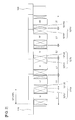
- a motor 100 according to the present embodiment is a linear synchronous motor which employs three-phase alternating current.
- Fig. 1 shows a case that a slot combination of the motor 100 is 5-pole and 6-slot (5P6S) as an example.
- the motor 100 has a stator 110 and a mover 120 which are arranged facing each other so as to be relatively movable via a magnetic air gap S.
- the stator 110 has a tabular yoke 111, and a plurality of permanent magnets 112 arranged on the yoke 111 at a fixed interval (at a magnet pitch MP) in a relative movement direction.
- the mover 120 has a core 121, and a mover base 122 made of resin, for example, and disposed so as to cover the core 121.
- the core 121 is structured such that split cores 125 each including a yoke 123 and teeth 124 disposed protruding from the yoke 123 to a magnetic air gap S side are arranged side by side at a fixed interval (at a teeth pitch TP) in a relative movement direction, and sub teeth 126 are arranged in both end portions of the split cores 125.
- the core 121 is formed as the split configuration, however, may be formed into an integral configuration.
- a plurality of coils 127 is wound around each of slots which are formed between the respective teeth 124 of the core 121.
- the slot combination is 5-pole and 6-slot (5P6S)
- two in-phase coils 127 are continuously arranged in the relative movement direction (a lateral direction in Fig. 2 ).
- Reference symbols U, V and W shown in Fig. 2 denote the respective coils 127 corresponding to a U phase, a V phase and a W phase, and the coils 127 having opposite winding direction thereto are respectively shown by -U, -V and -W.
- the mover 120 has a coil group including two continuously arranged in-phase coils 127 for each phase (U phase, V phase, W phase).
- the coil group 127U corresponding to the U phase has a first coil 127U1 and a second coil 127U2 which are two in-phase (U-phase) coils continuously arranged in the relative movement direction.
- wire diameters are the same in the first coil 127U1 and the second coil 127U2.
- the slot pitch SP is identical to a length in the relative movement direction of the yoke 123 in each of the split cores 125.
- the coil group 127V corresponding to the V phase has a first coil 127V1 and a second coil 127V2 which are continuously arranged in the relative movement direction, are in-phase (V-phase) coils and have the same wire diameter.
- the first coil 127V1 is structured such that a coil width L1 is larger than the slot pitch SP
- the second coil 127V2 is structured such that a coil width L2 is smaller than the slot pitch SP.
- the coil group 127W corresponding to the W phase has a first coil 127W1 and a second coil 127W2 which are continuously arranged in the relative movement direction, are in-phase (W-phase) coils and have the same wire diameter.
- the first coil 127W1 is structured such that a coil width L1 is larger than the slot pitch SP
- the second coil 127W2 is structured such that a coil width L2 is smaller than the slot pitch SP.
- the motor 100 has three sets of coil groups 127U, 127V, 127W shown in Fig. 2 in the relative movement direction, but the number of sets is not limited to this.
- the example is structured such that the mover 120 has the coil groups 127U, 127V, 127W, but the mover and the stator may be structured such that the stator has the coil groups 127U, 127V, 127W by inverting the corresponding relationship between the mover and the stator.
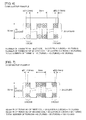
- the number of turns N1 of the first coil is 10 layers x 1 row (10 turns)
- the number of turns N2 of the second coil is 20 layers x 2 rows (40 turns)
- the wire diameter ⁇ D2 of the second coil (the coil in a right side of Fig.
- the number of turns N1 of the first coil is 20 layers x 2 rows (40 turns)
- the number of turns N2 of the second coil is 30 layers x 3 rows (90 turns)
- an intermediate number of turns can be obtained.
- the wire diameters are different for each coil, it is impossible to wind the continuous in-phase coil with a single stroke, and there is a problem that productivity is lowered.
- the inventors of the present application have derived overriding of the technical common sense that the coils are designed so that the coil width L of each coil is within the slot pitch SP, and have derived a configuration according to the present embodiment for the first time.
- the present embodiment is structured, as mentioned above, such that the in-phase coil groups 127U, 127V, 127W each including a plurality of (two in the present embodiment) coils which are continuously arranged and have the same wire diameter respectively have the coils 127U1, 127V1, 127W1 in which the coil width L1 is larger than the slot pitch SP.
- the coil width L is within the slot pitch SP.
- the number of turns N1 of the first coil (the coil in a left side of Fig. 8 ) is 15 layers x 2 rows (30 turns)
- the number of turns N2 of the second coil (the coil in a right side of Fig. 8 ) is 15 layers x 1 row (15 turns)
- the number of turns N1 of the first coil (the coil in a left side of Fig. 9 ) is 25 layers x 3 rows (75 turns)
- the number of turns N2 of the second coil (the coil in a right side of Fig. 9 ) is 25 layers x 2 row (50 turns)
- the present embodiment particularly has an effect that the space factor of the coil can be prevented from being lowered and the motor constant can be prevented from being lowered, in comparison with the case of application to a motor mentioned later in which three in-phase coils are continuously arranged, by application to the motor 100 of a slot combination in which two in-phase coils are continuously arranged.
- the first and second coils mentioned in Figs. 6 and 7 do not correspond to the first and second coils described in claims, but the first and second coils mentioned in Figs. 2 , 8 and 9 correspond to the first and second coils described in claims.
- the slot combination is 5-pole and 6-slot (5P6S) as an example, but the slot combination is not limited to this.
- the slot combination in which two in-phase coils are arranged there are additionally, for example, a slot combination of 7-pole and 6-slot (7P6S), a slot combination of 10-pole and 12-slot (10P12S) and a slot combination of 14-pole and 12-slot (14P12S), and the present disclosure can be applied to these motors.
- a motor having a slot combination in which three in-phase coils are continuously arranged without being limited to the motor in which two in-phase coils are continuously arranged.
- the slot combination in which three in-phase coils are continuously arranged there are, for example, a slot combination of 8-pole and 9-slot (8P9S) and a slot combination of 10-pole and 9-slot (10P9S).
- 8P9S 8-pole and 9-slot
- 10-pole and 9-slot 10P9S
- a mover 120 has a coil group including three continuously arranged in-phase coils 127 for each phase (U phase, V phase, W phase).
- a coil group 127U corresponding to the U phase has a first coil 127U1 and two second coils 127U2 which are three in-phase (U-phase) coils continuously arranged in the relative movement direction.
- a coil group 127V corresponding to the V phase and a coil group 127W corresponding to the W phase also have the same configuration as that of the coil group 127U.
- the arrangement relationship of the coil widths in the case that the coil groups 127U, 127V, 127W for each phase are arranged in the relative movement direction is "small, large, small", “small, large, small”, and "small, large, small”, and the arrangement can be dimensionally achieved. Therefore, in the motor having the slot combination in which three in-phase coils are continuously arranged, it is possible to realize a motor which can improve productivity while increasing the degree of freedom of the number of turns of the coil.
- a coil group 127U corresponding to the U phase has a first coil 127U1 in which a coil width L1 is larger than the slot pitch SP, and two second coils 127U2 which are arranged on one side in a relative movement direction of the first coil 127U1 (a right side in Fig. 12 in this example, in which a left side in Fig. 12 may be employed), and have coil widths L2 smaller than the slot pitch SP.
- the first coil 127U1 and two second coils 127U2 have the same wire diameter, and can be wound with a single stroke.
- a coil group 127V corresponding to the V phase and a coil group 127W corresponding to the W phase have the same configuration as the coil group 127U.
- an arrangement relationship of the coil widths in the case that the coil groups 127U, 127V and 127W for each phase are arranged in the relative movement direction is "large, small, small”, “large, small, small”, and “large, small, small”, or “small, small, large”, “small, small, large”, “small, small, large” and the arrangement can be dimensionally achieved. Therefore, in the motor having the slot combination in which three in-phase coils are continuously arranged, it is possible to realize a motor which can improve productivity while increasing the degree of freedom of the number of turns of the coil.
- the motor 100 is the linear synchronous motor as an example, but the present disclosure can be applied to a linear induction motor without being limited to this. Further, the present disclosure may be applied to a rotary type motor without being limited to the linear motor.
- the present invention can be executed by applying various changes within the range which does not deviate from the scope of the invention, although every change is not exemplified.
Landscapes
- Engineering & Computer Science (AREA)
- Power Engineering (AREA)
- Physics & Mathematics (AREA)
- Chemical & Material Sciences (AREA)
- Combustion & Propulsion (AREA)
- Electromagnetism (AREA)
- Windings For Motors And Generators (AREA)
- Linear Motors (AREA)
- Manufacture Of Motors, Generators (AREA)
Applications Claiming Priority (1)
| Application Number | Priority Date | Filing Date | Title |
|---|---|---|---|
| PCT/JP2011/080243 WO2013098949A1 (fr) | 2011-12-27 | 2011-12-27 | Moteur |
Publications (2)
| Publication Number | Publication Date |
|---|---|
| EP2800247A1 true EP2800247A1 (fr) | 2014-11-05 |
| EP2800247A4 EP2800247A4 (fr) | 2015-09-02 |
Family
ID=48696517
Family Applications (1)
| Application Number | Title | Priority Date | Filing Date |
|---|---|---|---|
| EP11878688.8A Withdrawn EP2800247A4 (fr) | 2011-12-27 | 2011-12-27 | Moteur |
Country Status (6)
| Country | Link |
|---|---|
| US (1) | US9172281B2 (fr) |
| EP (1) | EP2800247A4 (fr) |
| JP (1) | JP5293984B1 (fr) |
| KR (1) | KR101604936B1 (fr) |
| CN (1) | CN104011976B (fr) |
| WO (1) | WO2013098949A1 (fr) |
Families Citing this family (8)
| Publication number | Priority date | Publication date | Assignee | Title |
|---|---|---|---|---|
| CN105515334A (zh) * | 2015-12-18 | 2016-04-20 | 杨超 | 一种三相永磁直线电机八极九槽定子绕组 |
| DE202016008461U1 (de) * | 2016-11-03 | 2018-01-22 | Brose Fahrzeugteile GmbH & Co. Kommanditgesellschaft, Würzburg | Stator eines Elektromotors und Elektromotor |
| US10734876B2 (en) * | 2018-03-19 | 2020-08-04 | Denso International America, Inc. | Brushless motor for HVAC system |
| CN108616207A (zh) * | 2018-05-09 | 2018-10-02 | 同济大学 | 一种用于轨道交通的长定子直线电机绕组 |
| CN108599409A (zh) * | 2018-06-19 | 2018-09-28 | 珠海凌达压缩机有限公司 | 电机绕组、定子及同步电机 |
| CN110190726A (zh) * | 2019-05-30 | 2019-08-30 | 西南交通大学 | 动子、不等极距式双馈直线电机及其设计方法 |
| KR102761667B1 (ko) | 2019-11-06 | 2025-02-05 | 주식회사 코베리 | 선형 전동기 및 선형 전동기를 이용한 반송 시스템 |
| CN118435504B (zh) * | 2022-04-08 | 2025-06-27 | 三菱电机株式会社 | 模块型线性电动机 |
Family Cites Families (14)
| Publication number | Priority date | Publication date | Assignee | Title |
|---|---|---|---|---|
| US2394075A (en) * | 1941-02-26 | 1946-02-05 | Westinghouse Electric Corp | Generator and power plant therefor |
| US3466480A (en) * | 1967-04-14 | 1969-09-09 | Gen Electric | Commutation improvement for dynamoelectric machine |
| JPS5822575A (ja) | 1981-08-03 | 1983-02-09 | Nippon Telegr & Teleph Corp <Ntt> | サ−ボ用円筒状リニアインダクシヨンモ−タ |
| FR2726948B1 (fr) * | 1994-11-16 | 1996-12-20 | Wavre Nicolas | Moteur synchrone a aimants permanents |
| DE19740937A1 (de) * | 1997-09-17 | 1999-03-18 | Trw Fahrzeugelektrik | Stator und Verfahren zum Bewickeln eines Stators für einen bürstenlosen Gleichstrommotor |
| JP2004260985A (ja) | 2003-02-03 | 2004-09-16 | Sankyo Seiki Mfg Co Ltd | 回転電機の電機子およびそれを用いた回転電機、ならびに回転電機の電機子製造方法 |
| JP4304999B2 (ja) | 2003-02-14 | 2009-07-29 | 株式会社安川電機 | 3相電機子巻線およびそれを用いたモータ |
| JP2005261117A (ja) * | 2004-03-12 | 2005-09-22 | Honda Motor Co Ltd | 回転電機 |
| DE102006005046A1 (de) * | 2006-02-03 | 2007-08-09 | Siemens Ag | Elektrische Maschine mit ungleichmäßigen Polzähnen |
| DE102006035678A1 (de) * | 2006-07-31 | 2008-02-14 | Siemens Ag | Linearmotor mit Kraftwelligkeitsausgleich |
| DE102006061136A1 (de) * | 2006-12-22 | 2008-07-03 | Siemens Ag | Kurzhublinearmotor |
| JP2008211918A (ja) | 2007-02-27 | 2008-09-11 | Kokusan Denki Co Ltd | 回転電機 |
| DE102008057349B3 (de) * | 2008-11-14 | 2010-07-15 | Feaam Gmbh | Elektrische Maschine |
| US8436504B2 (en) * | 2010-01-11 | 2013-05-07 | Ford Global Technologies, Llc | Stator for an electric machine |
-
2011
- 2011-12-27 JP JP2012554550A patent/JP5293984B1/ja active Active
- 2011-12-27 WO PCT/JP2011/080243 patent/WO2013098949A1/fr not_active Ceased
- 2011-12-27 KR KR1020147017684A patent/KR101604936B1/ko active Active
- 2011-12-27 CN CN201180075933.1A patent/CN104011976B/zh active Active
- 2011-12-27 EP EP11878688.8A patent/EP2800247A4/fr not_active Withdrawn
-
2014
- 2014-06-24 US US14/312,694 patent/US9172281B2/en active Active
Also Published As
| Publication number | Publication date |
|---|---|
| WO2013098949A1 (fr) | 2013-07-04 |
| KR101604936B1 (ko) | 2016-03-18 |
| US9172281B2 (en) | 2015-10-27 |
| EP2800247A4 (fr) | 2015-09-02 |
| KR20140096389A (ko) | 2014-08-05 |
| JPWO2013098949A1 (ja) | 2015-04-30 |
| US20140300212A1 (en) | 2014-10-09 |
| CN104011976B (zh) | 2016-08-24 |
| CN104011976A (zh) | 2014-08-27 |
| JP5293984B1 (ja) | 2013-09-18 |
Similar Documents
| Publication | Publication Date | Title |
|---|---|---|
| US9172281B2 (en) | Motor | |
| US9793772B2 (en) | Stator for rotating electric machine | |
| US20130015742A1 (en) | Synchronous motor | |
| US20170324294A1 (en) | Wave Winding Having A Low Cogging Torque, Stator And Electric Machine Comprising A Wave Winding Of Said Type | |
| JP5574173B2 (ja) | 永久磁石形同期リニアモータおよびそれを用いたテーブル送り装置 | |
| US20150222167A1 (en) | Linear Motor and Linear Motor Drive System | |
| EP3214733B1 (fr) | Machine électrique tournante | |
| CN104426315B (zh) | 三相电磁电机 | |
| EP1999838B1 (fr) | Dispositif d'enroulement en étoile pour une machine électrique tournante | |
| WO2017110760A1 (fr) | Machine électrique tournante et procédé de fabrication associé | |
| CN108736614B (zh) | 旋转电机的定子 | |
| JP2007259541A (ja) | 永久磁石式電動機 | |
| KR101308154B1 (ko) | 영구자석형 선형 동기전동기 및 회전형 동기전동기 | |
| US20140152140A1 (en) | Electric Machine And Method For Winding A Coil Of An Electric Machine | |
| JP5987789B2 (ja) | リニアモータ | |
| US11955864B2 (en) | Linear motor | |
| JP2006129546A (ja) | ムービングコイル形リニアモータ | |
| JP6582973B2 (ja) | 回転電機およびその製造方法 | |
| US20240048006A1 (en) | Stator for an electric machine, electric machine for driving a vehicle, and vehicle | |
| JP6610415B2 (ja) | 三相同期機およびその製造方法 | |
| JP4475059B2 (ja) | リニア電動機 | |
| JP2518206B2 (ja) | ブラシレス直流リニアモ−タの巻線方法 | |
| JP4710307B2 (ja) | ハイブリッド型パルスモータ | |
| KR101308155B1 (ko) | 영구자석형 선형 동기전동기 및 회전형 동기전동기 | |
| JP2017201855A (ja) | ステータおよび当該ステータを備えたモータ |
Legal Events
| Date | Code | Title | Description |
|---|---|---|---|
| PUAI | Public reference made under article 153(3) epc to a published international application that has entered the european phase |
Free format text: ORIGINAL CODE: 0009012 |
|
| 17P | Request for examination filed |
Effective date: 20140619 |
|
| AK | Designated contracting states |
Kind code of ref document: A1 Designated state(s): AL AT BE BG CH CY CZ DE DK EE ES FI FR GB GR HR HU IE IS IT LI LT LU LV MC MK MT NL NO PL PT RO RS SE SI SK SM TR |
|
| DAX | Request for extension of the european patent (deleted) | ||
| RA4 | Supplementary search report drawn up and despatched (corrected) |
Effective date: 20150731 |
|
| RIC1 | Information provided on ipc code assigned before grant |
Ipc: H02K 3/28 20060101ALI20150727BHEP Ipc: H02K 3/18 20060101AFI20150727BHEP Ipc: H02K 41/03 20060101ALI20150727BHEP |
|
| GRAP | Despatch of communication of intention to grant a patent |
Free format text: ORIGINAL CODE: EPIDOSNIGR1 |
|
| GRAJ | Information related to disapproval of communication of intention to grant by the applicant or resumption of examination proceedings by the epo deleted |
Free format text: ORIGINAL CODE: EPIDOSDIGR1 |
|
| STAA | Information on the status of an ep patent application or granted ep patent |
Free format text: STATUS: THE APPLICATION HAS BEEN WITHDRAWN |
|
| RIC1 | Information provided on ipc code assigned before grant |
Ipc: H02K 3/28 20060101ALI20160707BHEP Ipc: H02K 41/03 20060101ALI20160707BHEP Ipc: H02K 3/18 20060101AFI20160707BHEP |
|
| 18W | Application withdrawn |
Effective date: 20160719 |