EP2800250A1 - Machine électrique dotée d'un capot de protection et stator correspondant - Google Patents
Machine électrique dotée d'un capot de protection et stator correspondant Download PDFInfo
- Publication number
- EP2800250A1 EP2800250A1 EP13165794.2A EP13165794A EP2800250A1 EP 2800250 A1 EP2800250 A1 EP 2800250A1 EP 13165794 A EP13165794 A EP 13165794A EP 2800250 A1 EP2800250 A1 EP 2800250A1
- Authority
- EP
- European Patent Office
- Prior art keywords
- printing device
- stator
- electric machine
- protective hood
- fastening element
- Prior art date
- Legal status (The legal status is an assumption and is not a legal conclusion. Google has not performed a legal analysis and makes no representation as to the accuracy of the status listed.)
- Withdrawn
Links
Images



Classifications
-
- H—ELECTRICITY
- H02—GENERATION; CONVERSION OR DISTRIBUTION OF ELECTRIC POWER
- H02K—DYNAMO-ELECTRIC MACHINES
- H02K9/00—Arrangements for cooling or ventilating
- H02K9/14—Arrangements for cooling or ventilating wherein gaseous cooling medium circulates between the machine casing and a surrounding mantle
- H02K9/18—Arrangements for cooling or ventilating wherein gaseous cooling medium circulates between the machine casing and a surrounding mantle wherein the external part of the closed circuit comprises a heat exchanger structurally associated with the machine casing
-
- H—ELECTRICITY
- H02—GENERATION; CONVERSION OR DISTRIBUTION OF ELECTRIC POWER
- H02K—DYNAMO-ELECTRIC MACHINES
- H02K5/00—Casings; Enclosures; Supports
- H02K5/04—Casings or enclosures characterised by the shape, form or construction thereof
- H02K5/10—Casings or enclosures characterised by the shape, form or construction thereof with arrangements for protection from ingress, e.g. water or fingers
-
- H—ELECTRICITY
- H02—GENERATION; CONVERSION OR DISTRIBUTION OF ELECTRIC POWER
- H02K—DYNAMO-ELECTRIC MACHINES
- H02K1/00—Details of the magnetic circuit
- H02K1/06—Details of the magnetic circuit characterised by the shape, form or construction
- H02K1/12—Stationary parts of the magnetic circuit
- H02K1/16—Stator cores with slots for windings
-
- H—ELECTRICITY
- H02—GENERATION; CONVERSION OR DISTRIBUTION OF ELECTRIC POWER
- H02K—DYNAMO-ELECTRIC MACHINES
- H02K1/00—Details of the magnetic circuit
- H02K1/06—Details of the magnetic circuit characterised by the shape, form or construction
- H02K1/12—Stationary parts of the magnetic circuit
- H02K1/18—Means for mounting or fastening magnetic stationary parts on to, or to, the stator structures
-
- H—ELECTRICITY
- H02—GENERATION; CONVERSION OR DISTRIBUTION OF ELECTRIC POWER
- H02K—DYNAMO-ELECTRIC MACHINES
- H02K1/00—Details of the magnetic circuit
- H02K1/06—Details of the magnetic circuit characterised by the shape, form or construction
- H02K1/12—Stationary parts of the magnetic circuit
- H02K1/18—Means for mounting or fastening magnetic stationary parts on to, or to, the stator structures
- H02K1/185—Means for mounting or fastening magnetic stationary parts on to, or to, the stator structures to outer stators
-
- H—ELECTRICITY
- H02—GENERATION; CONVERSION OR DISTRIBUTION OF ELECTRIC POWER
- H02K—DYNAMO-ELECTRIC MACHINES
- H02K3/00—Details of windings
- H02K3/46—Fastening of windings on the stator or rotor structure
- H02K3/50—Fastening of winding heads, equalising connectors, or connections thereto
-
- H—ELECTRICITY
- H02—GENERATION; CONVERSION OR DISTRIBUTION OF ELECTRIC POWER
- H02K—DYNAMO-ELECTRIC MACHINES
- H02K5/00—Casings; Enclosures; Supports
- H02K5/04—Casings or enclosures characterised by the shape, form or construction thereof
- H02K5/22—Auxiliary parts of casings not covered by groups H02K5/06-H02K5/20, e.g. shaped to form connection boxes or terminal boxes
- H02K5/225—Terminal boxes or connection arrangements
Definitions
- the invention relates to an electrical machine according to the preamble of patent claim 1 and a stator for the electric machine. Furthermore, the invention relates to a method for producing the stator and a method for producing the electrical machine.
- Such an electrical machine is used to convert electrical to mechanical energy and vice versa.
- the electric machine When converting from mechanical to electrical energy, the electric machine is used as a generator.
- the electric machine When converting from electrical to mechanical energy, the electric machine is used as a motor.
- the electric machine Depending on the power requirement on the electrical machine, its dimensions and the ambient conditions, the electric machine has a cooling device for this purpose.
- the WO 2012/159660 A2 electrical machines which are based on a platform concept that make all types of cooling individually or in combination, such as self-or externally ventilated, water-cooled or water-cooled with forced ventilation, as well as a separate attachment cooler feasible. Depending on the place of use and climatic requirements, the electrical machines can thus be adapted to the conditions with optimum efficiency in a simple manner.
- the platform concept is based on a self-supporting housing. It is there in an embodiment of the degree of protection according to IEC 34-5, which requires a protective cover, during a mounting operation, a laminated core with a winding, not shown, and a protective cover axially inserted into the housing.
- the cited publication shows protective covers that cover the winding system and / or the filling tubes and so against external influences depending on the requirement of the protection according to IEC 34-5 protect. Ribs or beads stiffen the protective covers.
- the invention is therefore an object of the invention to provide an electrical machine available, in which a simple protection against environmental influences is achieved.
- stator for an electric machine having the features of claim 12.
- the first printing device has the second fastening region.
- the object is also achieved by a method for producing a stator having the features of claim 13.
- the first protective hood on the first printing device is fastened to a connection point by a fastening unit which has a first fastening region on the first protective hood and a second fastening region on the first printing device.
- the first protective hood is attached to the first printing device fixed to a connection point by a fastening unit which has a first fastening region on the first protective hood and a second fastening region on the first printing device.
- the electric machine according to the invention achieves the object advantageously in that the fastening unit, which has a first fastening region on the first protective hood and a second fastening region on the first printing device, makes it possible to fix both the first protective hood during assembly at the connection point and the first one Protective cover to be attached to the first printing device.
- the protection against environmental influences includes preventing the penetration of environmental influences into an inner region of the electrical machine with high quality.
- the winding may include a first winding head surrounded by the first guard, wherein the first guard may extend in the axial direction at least from the first printing device to a first end of the first winding head remote from the first printing device.
- the rotor When operating an electric machine according to the invention as a generator, the rotor is set in rotation by mechanical energy. By a magnetic interaction between rotor and stator, the mechanical energy can be converted into electrical energy. The electrical energy can be taken from the winding, which is arranged at the air gap, by connecting an electrical load. The winding can be attached to the stator.
- electrical energy is supplied via the winding and converted by the magnetic interaction between the stator and rotor electrical energy into mechanical energy.
- the rotor is set in rotation and it can be delivered to a shaft mechanical energy to a mechanical load in the form of a rotary motion.
- the winding may be attached to the stator.
- the laminated in the axial direction sheets are used to guide the magnetic flux in an operation of the electric machine.
- suitable sheets are, for example, electrical sheets.
- the rotor has a corresponding device in order to be able to interact magnetically with the stator via the air gap.
- the device may for this purpose have a permanent magnet and / or a winding.
- the electric machine has a plurality of fastening units, which are respectively present in regions in different radial directions at the first axial end of the stator.
- the attachment units may advantageously be present in the regions in the different radial directions in which a distance of the edges of the layered sheets to the air gap is greater than in other areas of the layered sheets.
- an area which is used electromagnetically for operating the electric machine can advantageously be used for the fastening units.
- the fixing units are provided in the areas of the corners of the first printing apparatus and the first protective hood which correspond to the corners of the laminated sheets.
- the first printing device applies a pressing force to the laminated sheets in the axial direction.
- the stator may include a second pressure device disposed at the second axial end.
- the winding may extend from the first axial end to the second axial end, the winding having the first winding head at the first axial end and a second winding head at the second axial end.
- the second The winding head may be surrounded by a second protective hood, wherein the second protective hood may extend in the axial direction at least from the second printing device to a second end of the second winding head, which faces away from the second printing device.
- the second protective hood can advantageously be fastened to the second printing device by a further fastening unit, which has a first fastening region on the second protective hood and a second fastening region on the second printing device, fixed to a connection point.
- the first printing device may have in the axial direction an arrangement of a first pressure plate and a second pressure plate, wherein the first pressure plate is arranged closer to the laminated core than the second pressure plate.
- the first printing device can thus advantageously maintain the pressure force when exposed to environmental influences.
- the first printing device with the first and second printing plates advantageously reduces fanning of the layered sheets at an edge of the printing device or sheets. In a fanning of the layered sheets environmental influences can affect more strongly on the electric machine. Thus, e.g. Moisture into the stator and penetrate the rotor.
- the first and the second pressure plate can be advantageously produced, since they do not have to be cambered.
- the first pressure plate may extend at least partially along teeth that the stator has and which extend into the air gap.
- a fanning of the layered sheets on the teeth is advantageously reduced.
- At least some of the teeth may advantageously form part of a boundary of grooves, wherein in the grooves the winding is guided.
- Recesses, which are for example for forming the teeth, attached to the first and the second pressure plate can be advantageously made easier and with higher accuracy. This is possible, inter alia, because the first and second printing plates can be made thinner than with only one printing plate in the printing device.
- the first pressure plate may advantageously extend over more than 80% of the length of the teeth along the teeth into the air gap due to the simpler and more accurate manufacture possible.
- a stator according to the invention has the further advantage that it has the second fastening region of the fastening unit in a space-saving and cost-effective manner.
- a stator according to the invention can be used both in an electrical machine which has the first protective hood and in an electrical machine which has no protective hood, without further adaptation.
- An inventive method for producing a stator according to the invention also has the further advantage that a simpler positioning and attachment of the first protective hood is advantageously possible.
- An inventive method for producing an electrical machine according to the invention also has the further advantage that the advantageous fastening unit obstructs mounting of the stator in the electric machine, in particular in a housing of the electric machine, in all different types of cooling to a small extent.
- the first protective hood on the stator be attached that it can be mounted in the electric machine advantageous.
- an embodiment of the electric machine according to the invention is advantageous in which the fastening unit has a first and a second fastening element, wherein a thickness d of a sealing layer is fixed at the connection point between the first protective hood and the first printing device by the first fastening element and by a connection, comprising the first and second fasteners, the second fastener extending along an axial direction is attached to the first printing device. It is so advantageous in a simple way a protection against environmental influences achieved by the first fastener space-saving and inexpensive both the second fastener attached to the first printing device, as well as a thickness d of the sealing layer determines a good sealing effect against environmental influences.
- such a sealing layer can be used, which is very flexible and thus applies in an ideal manner to the first printing device, in particular to the second pressure plate and the first protective hood.
- the sealing layer e.g. may advantageously have a rubber, may have a corresponding flexibility and compressibility.
- the sealing layer may also advantageously be a material which at the junction the space between the first Protective hood and the first printing device in an axial direction does not completely fill or not with the required sealing effect. This is achieved in the production of the stator after attaching the first protective hood to the first printing device by a further manufacturing step. In this further production step, the extent of the material of the sealing layer is increased in the axial direction. The enlargement of the extension in the axial direction can take place by a chemical or physical reaction of the material of the sealing layer by incorporating a further material in the sealing layer.
- the sealing layer may comprise a swollen material.
- the second pressure plate can be fastened to the first pressure device by the connection which has the first and the second fastening element.
- the second fastening element has a first region, which is arranged in a first recess of the first printing device in a form-fitting manner to avoid twisting about an axial direction by more than 360 °.
- the first recess may be advantageous on the first pressure plate of the first printing device. So is a space-saving and inexpensive easy insertion of the second fastener achieved and a fixing of the second fastener against twisting in the manufacture of a stator according to the invention or an electrical machine according to the invention avoided.
- an edge of the first printing device is interrupted at the second fastening region by a recess on the first printing device.
- the second fastening element can be attached to the edge of the first printing device in the recess in a simple manner.
- Both an edge of the first pressure plate and an edge of the second pressure plate is advantageously interrupted by the recess.
- the first protective hood can advantageously have a recess which, in an axial direction, continues the interruption of the edge of the first printing device. As a result, a fixing and fixing of the first protective hood can be carried out in a simpler manner.
- the recess of the second pressure plate may have a smaller extent than the first recess of the first pressure plate in a direction perpendicular to an axial direction.
- the second fastening element can be held in a simple manner additionally by a clearance-free arrangement of the second fastening element in the recess of the second pressure plate prior to connection to the first fastening element.
- the second fastening element can be arranged without play in a direction perpendicular to an axial direction.
- the second fastening element can be additionally held in a simple manner by the play-free arrangement in the recess of the second pressure plate prior to connection to the first fastening element.
- the first protective hood is fastened to the first pressure arrangement by a connection which has the first, the second and a third fastening element, wherein the fastening unit comprises the third fastening element.
- the first protective hood has an edge at the connection point, which extends along a side of the winding facing away from the air gap in radial directions and wherein the edge is formed by an edge of the first protective hood.
- the edge of the first protective hood advantageously has an almost identical thickness in all radial and axial directions. The thickness may be given by being advantageously made by a disk-shaped material.
- the edge of the first protective hood can be produced from a disk-shaped material by simple processes, for example by bending or edges, from a metal sheet. Subsequently, the first attachment area can be attached to the first guard.
- the first attachment portion may consist of a simple construction element, or may have a simple construction element.
- the construction element may e.g. be a hole or an L-angle, which has a recess.
- the simple construction elements can be produced inexpensively in a simple manner.
- the disk-shaped material may be a sheet.
- the thermal conductivity of the sheet can contribute so advantageous for cooling the electric machine.
- the disc-shaped material may be a plastic. This has the advantage that the first protective hood can be produced by cost-effective processes in plastics processing.
- the first protective hood has an opening, from which terminals of the winding can be guided in radial directions through the first protective hood.
- the second fastening element has a screw
- the first fastening element has a nut
- a screw-nut connection which has the first fastening element and the second fastening element, between the first and the second fastening element by a fixing element are made operationally stable.
- a screw-nut connection can be formed only from the first and the second fastening element, so that a thickness d of a sealing layer at the junction between the first protective hood and the first printing device is determined by the first fastening element advantageous.
- the third fastening element has a nut.
- a screw-nut connection which has the second fastening element and the third fastening element, between the second and the third fastening element by a fixing element are made operationally stable.
- the second fastener a screw, the first fastener a nut and the third fastener having a nut, wherein a screw-nut connection comprises the screw and the nut of the first fastener and a screw-nut connection, the screw and the nut of have third fastening means.
- the fastening unit can advantageously be assembled in a space-saving and cost-effective manner, as well as gradually, in order to secure the first protective hood to the first printing device at a connection point.
- FIG. 1 shows an embodiment of an electric machine 1.
- the electric machine 1 comprises a stator 2, which has a laminated core 3, which comprises in an axial direction 8 layered sheets 31.
- the layered sheets 31 are arranged from a first axial end 32 to a second axial end 33.
- the electric machine has a rotor 4, which is rotatably mounted about an axially extending axis of rotation 5 and cooperates in an operation of the electric machine 1 via an air gap 6 with the stator 2.
- the electric machine 1 comprises a winding 7, which is arranged at the air gap 6, and a first protective hood 11.
- the air gap 6 is bounded in radial directions 9, which are oriented perpendicular to the axial direction 8, by the stator 2 and the rotor 4 ,
- the stator 2 has a first printing device 10 which is connected to the first axial end 32 is arranged.
- the first protective hood 11 is fastened to the first printing device 10 at a connection point 12 by a fastening unit 13 which has a first fastening region 1311 on the first protective hood 11 and a second fastening region 1310 on the first printing device 10.
- the fixing unit 13 is provided in the areas of the corners of the first printing apparatus 10 and the first protective hood 11, which correspond to the corners of the laminated sheets 31.
- the laminated sheets 31 have an octagonal basic shape formed of short and long outer edges 301 of the laminated sheets 31. In areas having the short outer edges 301, the distance of the outer edges 301 of the laminated sheets 31 to the air gap 6 is larger than in other areas of the laminated sheets 31.
- the electric machine 1 has a housing 1001 in which the stator 2 is arranged.
- the winding 7 has a first winding head 71, which surrounds the first protective hood 11, the first protective hood 11 extending in the axial direction 8 at least from the first printing device 10 to a first end of the first winding head 71, that of the first printing device 10 turned away.
- the first printing device 10 applies a pressing force to the laminated sheets 31 in the axial direction 8.
- the stator 2 has a second pressure device, which is arranged at the second axial end 33.
- the winding 7 extends from the first axial end 32 to the second axial end 33, the winding 7 having the first winding head 71 at the first axial end 32 and a second winding head 72 at the second axial end 33.
- the winding 7 is guided in grooves 21 of the stator 2.
- the grooves 21 are in the FIG. 3 to recognize better due to the perspective view.
- the housing 1001 has bearing plates 22, in which by means of rolling bearings, a shaft on which the rotor 4 is fixed, is rotatably mounted about the axially extending axis of rotation 5.
- the rotor 4 has channels which extend in an axial direction 8 through the rotor 4.
- the rotor 4 has deflection devices 25 at the first axial end 32.
- the laminated core 3 and the first printing device 10 have axial inner channels 50, the openings 501 of which are located within an inner region.
- the inner region of the electric machine 1 comprises the rotor 4, the first winding head 71, the second winding head 72 and the stator 2 in its radial extent up to the axial inner channels 50.
- the axially inner channels 50 thus still belong to the inner region of the electrical Machine 1.
- the first guard 11 surrounds the inner region into a portion between one of the end shields 22 and the first pressure device 10.
- an inner coolant stream 24 may flow through the inner channels 50 and the channels of the rotor 4 and be protected from environmental influences for equalization the temperature in an inner region of the electric machine 1 provide.
- the inner coolant stream 24 partially flows along the first protective hood 11 and can advantageously deliver heat there to an outer coolant stream 26.
- the first protective hood 11 has predominantly a disk-shaped material 27.
- the disk-shaped material 27 was formed into a shape by bending and edging so that the disk-shaped material 27 surrounds the winding heads 71 at the first axial end 32.
- the inner coolant flow 24 and the outer coolant flow 26 are passed through the disc-shaped material 27 without appreciable impediment to the flow along the axial direction 8, and due to the small thickness of the disc-shaped material, the heat from the inner coolant flow 24 can be transferred to the outer Coolant stream 26 are transmitted.
- the outer coolant flow 26 flows through openings in the housing 1001 of the electric machine 1 and is there moved by a fan 15 through openings of a bearing plate 22 along the second protective hood 110, which is designed like the first protective hood 11.
- the outer coolant stream 26 then flows through axial outer channels 40, 41 which have the laminated core 3 and the first pressure device 10 and whose openings 401, 411, 412 are located outside the inner region. Subsequently, the outer coolant stream 26 flows along the first protective hood 11 and leaves the electrical machine 1 via openings of a bearing plate 22.
- the axial outer channels 40, 41 are formed on the laminated sheets 31 by recesses which interrupt the outer edges 301 of the laminated sheets 31 ,
- the first printing device 10 has, in the axial direction 8, an arrangement of a first printing plate 101 and a second printing plate 102, the first printing plate 101 being arranged closer to the laminated core 3 than the second printing plate 102.
- the fastening unit 13 has a first and a second fastening element 131, 132, wherein by the first fastening element 131, a thickness d of a sealing layer 14 at the junction 12 between the first protective hood 11 and the first printing device 10 is fixed and by a connection through the first fixing member 131 and the second fixing member 132 is formed, the second fixing member 132 extending along an axial direction 8 is fixed to the first printing apparatus 10.
- FIG. 2 shows an embodiment of a stator, the embodiment of the electric machine according to FIG. 1 having.
- the stator 2 comprises a lamination stack 3 comprising laminations 31 stacked in an axial direction 8 arranged from a first axial end 32 to a second axial end 33, the stator 2 having a first pressure device 10 attached to the first one axial end 32 is arranged, and wherein the first printing device 10 has a second attachment portion 1310.
- the stator 2 is for the electric machine 1 of FIG. 1 in which the stator 2 surrounds the rotor 4. Accordingly, the winding 7 is located predominantly in an axial bore 28 within the laminated core 3.
- the first printing device 10 in the axial direction 8, an arrangement of a first pressure plate 101 and a second pressure plate 102, wherein the first pressure plate 101 is disposed closer to the laminated core 3 than the second pressure plate 102.
- the first and the second Pressure plate 101, 102 have the second attachment area in one of the corners corresponding to the corners of the laminated sheets 31.
- the laminated core 3 and the first pressure device 10 have the axial inner channels 50, the opening 501 of which are located within the inner region of the electric machine 1.
- the first and second pressure plates 101, 102 have the openings 501 located within the first radial area.
- FIG. 2 shows a dot-dash line with a line of sight I for orientation, these show approximately the line of intersection and line of sight, with the stator 2 in FIG. 1 is shown.
- FIG. 1 In connection with the description of the FIG. 2 used reference numerals not in FIG. 2 may exist accordingly FIG. 1 be removed.
- An inventive stator for example, the embodiment of the stator 2 according to FIG. 2 can be advantageously used without first protective hood 11 and without a second protective hood 11 in an electrical machine, if this only has to meet a degree of protection that does not require first and second protective hood 11, 110 to protect against environmental influences.
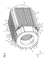
- FIG. 3 shows a view of the stator according to FIG. 2 , wherein a first protective hood 11 is attached according to the invention.
- the first protective hood 11 has an opening 113, from which connections 70 of the winding 7 can be guided in radial directions 9 through the first protective hood 11.
- the other components of the stator 2 have already been associated with FIG. 2 and FIG. 1 described.
- FIG. 3 are also the already mentioned grooves in the axial bore 28 to see in which the winding 7 is guided.
- FIG. 4 shows a detail of a plan view of the embodiment of the stator according to the FIG. 3 in the region of the fastening unit 13.
- the second fastening element 132 has a first region 1321 which is arranged in a first recess 1010 of the first printing device 10 in a form-fitting manner to avoid twisting about an axial direction 8 by more than 360 °.
- the first recess 1010 is located on the first pressure plate 101.
- the second fastening element 132 is a screw.
- the first region 1321 is the head of the screw, which is an external hex head.
- An edge 1011, 1021 of the first printing device 10 is interrupted at the second fastening region 1310 by a recess 1110, 1010 on the first printing device 10.
- the recess 1110, 1010 has the first recess 1010 on the first pressure plate 101 and a second recess 1110 on the second pressure plate 102.
- the second fastening element 132 is arranged without play in a direction perpendicular to the axial direction 8.
- the second fastening means 132 is attached to the first printing device 10 by a connection formed by the first fastening element 131 and the second fastening element 132. Subsequently, the first protective hood 11 is connected by a connection, the first, second and third fastener 131,132,133, attached to the first printing device 10.
- the fastening unit 13 comprises the third fastening element 133.
- the first fastening element 131 defines a thickness d of a sealing layer 14 at the connection point 12 between the first protective hood 11 and the first pressure device 10.
- the second fastener 132 is a screw having an outer hex head in the first region 1321.
- the first fastening element 131 and the third fastening element 133 are nuts.
- a screw-nut connection has the first fastening element 131 and the second fastening element 132.
- Another screw-nut connection comprises the second fastening element 132 and the third fastening element 133.
- the further screw-nut connection has a spring ring 1331 as a fixing element.
- the spring ring 1331 is in the embodiment of FIG. 4 used for additional securing the screw-nut connection.
- the two screw-nut connections can thus have further elements, as long as the basic features according to the invention are not deviated from.
- the first protective hood 11 has a recess in a fastening piece 112, in which the second fastening means 132 is arranged without play in a direction perpendicular to an axial direction 8.
- the attachment piece 112 is firmly bonded to the first protective hood 11 by a welding process.
- FIG. 5 shows a detail of an embodiment of the stator 2 after a manufacturing step according to the invention prior to attaching the first protective cover 11.
- a sealing layer 14 is disposed on the first printing device 10.
- the sealing layer has a rubber.
- the determination according to the invention of the thickness d of the sealing layer 14 by the first fastening element 131 also allows the use of a sealing layer 14 which allows an increase in the extent of the material of the sealing layer 14 in the axial direction 8 by a chemical or physical reaction of the material.
- the sealing layer 14 has a felt which, in a further production step of a stator 2 according to the invention or an electrical machine 1 according to the invention, swells onto the felt by the action of a liquid substance.
- the invention has been more particularly determined by the preferred embodiments, it is not limited to the disclosed examples. Other variations can be deduced therefrom by those skilled in the art without departing from the scope of the invention. So it would also be e.g. conceivable that the first guard has a flange which is arranged at the connection point, wherein not all advantages of the invention are achieved.
Landscapes
- Engineering & Computer Science (AREA)
- Power Engineering (AREA)
- Motor Or Generator Frames (AREA)
- Manufacture Of Motors, Generators (AREA)
- Iron Core Of Rotating Electric Machines (AREA)
Priority Applications (6)
| Application Number | Priority Date | Filing Date | Title |
|---|---|---|---|
| EP13165794.2A EP2800250A1 (fr) | 2013-04-29 | 2013-04-29 | Machine électrique dotée d'un capot de protection et stator correspondant |
| EP14719665.3A EP2992593B1 (fr) | 2013-04-29 | 2014-04-10 | Machine électrique pourvue d'un enveloppe protectrice et stator associé |
| BR112015027365A BR112015027365A2 (pt) | 2013-04-29 | 2014-04-10 | máquina elétrica, estator para uma máquina elétrica, métodos para produzir um estator e uma máquina elétrica |
| RU2015146200A RU2608777C1 (ru) | 2013-04-29 | 2014-04-10 | Электрическая машина с защитным кожухом и статор для нее |
| PCT/EP2014/057276 WO2014177356A2 (fr) | 2013-04-29 | 2014-04-10 | Machine électrique pourvue d'un enveloppe protectrice et stator associé |
| CN201480024184.3A CN105191075B (zh) | 2013-04-29 | 2014-04-10 | 电机、电机的定子、制造定子的方法和制造电机的方法 |
Applications Claiming Priority (1)
| Application Number | Priority Date | Filing Date | Title |
|---|---|---|---|
| EP13165794.2A EP2800250A1 (fr) | 2013-04-29 | 2013-04-29 | Machine électrique dotée d'un capot de protection et stator correspondant |
Publications (1)
| Publication Number | Publication Date |
|---|---|
| EP2800250A1 true EP2800250A1 (fr) | 2014-11-05 |
Family
ID=48184095
Family Applications (2)
| Application Number | Title | Priority Date | Filing Date |
|---|---|---|---|
| EP13165794.2A Withdrawn EP2800250A1 (fr) | 2013-04-29 | 2013-04-29 | Machine électrique dotée d'un capot de protection et stator correspondant |
| EP14719665.3A Active EP2992593B1 (fr) | 2013-04-29 | 2014-04-10 | Machine électrique pourvue d'un enveloppe protectrice et stator associé |
Family Applications After (1)
| Application Number | Title | Priority Date | Filing Date |
|---|---|---|---|
| EP14719665.3A Active EP2992593B1 (fr) | 2013-04-29 | 2014-04-10 | Machine électrique pourvue d'un enveloppe protectrice et stator associé |
Country Status (5)
| Country | Link |
|---|---|
| EP (2) | EP2800250A1 (fr) |
| CN (1) | CN105191075B (fr) |
| BR (1) | BR112015027365A2 (fr) |
| RU (1) | RU2608777C1 (fr) |
| WO (1) | WO2014177356A2 (fr) |
Families Citing this family (3)
| Publication number | Priority date | Publication date | Assignee | Title |
|---|---|---|---|---|
| CN106385122A (zh) * | 2016-09-20 | 2017-02-08 | 北京交通大学 | 电机的蜂巢式密闭通风冷却装置 |
| CN107659010A (zh) * | 2017-10-30 | 2018-02-02 | 南京磁谷科技有限公司 | 一种电机定子的压紧结构 |
| JP6974760B2 (ja) * | 2019-11-29 | 2021-12-01 | ダイキン工業株式会社 | モータ組立体、及び、空気調和装置 |
Citations (3)
| Publication number | Priority date | Publication date | Assignee | Title |
|---|---|---|---|---|
| US20040150270A1 (en) * | 2002-11-25 | 2004-08-05 | Takashi Nagayama | Fully enclosed type motor with outer fans |
| US20120126642A1 (en) * | 2010-11-18 | 2012-05-24 | Aisin Seiki Kabushiki Kaisha | Electric motor |
| WO2012159660A2 (fr) | 2011-05-24 | 2012-11-29 | Siemens Aktiengesellschaft | Machine dynamoélectrique à boîtier autoporteur |
Family Cites Families (5)
| Publication number | Priority date | Publication date | Assignee | Title |
|---|---|---|---|---|
| CS165658B1 (fr) * | 1971-04-20 | 1975-12-22 | ||
| SU1746478A1 (ru) * | 1990-06-25 | 1992-07-07 | Филиал Всесоюзного Научно-Иследовательского Института Электромашиностроения По Крупным Электрическим Машинам | Электрическа машина |
| DE102010002068A1 (de) * | 2010-02-18 | 2011-08-18 | Siemens Aktiengesellschaft, 80333 | Motoreinheit |
| CN201699536U (zh) * | 2010-05-27 | 2011-01-05 | 西安盾安电气有限公司 | 采用空水冷却方式的风力发电机 |
| CN103051082B (zh) * | 2012-12-30 | 2015-06-03 | 南车株洲电机有限公司 | 一种定子铁心固定结构及箱式电机 |
-
2013
- 2013-04-29 EP EP13165794.2A patent/EP2800250A1/fr not_active Withdrawn
-
2014
- 2014-04-10 EP EP14719665.3A patent/EP2992593B1/fr active Active
- 2014-04-10 CN CN201480024184.3A patent/CN105191075B/zh active Active
- 2014-04-10 WO PCT/EP2014/057276 patent/WO2014177356A2/fr not_active Ceased
- 2014-04-10 RU RU2015146200A patent/RU2608777C1/ru not_active IP Right Cessation
- 2014-04-10 BR BR112015027365A patent/BR112015027365A2/pt not_active Application Discontinuation
Patent Citations (3)
| Publication number | Priority date | Publication date | Assignee | Title |
|---|---|---|---|---|
| US20040150270A1 (en) * | 2002-11-25 | 2004-08-05 | Takashi Nagayama | Fully enclosed type motor with outer fans |
| US20120126642A1 (en) * | 2010-11-18 | 2012-05-24 | Aisin Seiki Kabushiki Kaisha | Electric motor |
| WO2012159660A2 (fr) | 2011-05-24 | 2012-11-29 | Siemens Aktiengesellschaft | Machine dynamoélectrique à boîtier autoporteur |
Also Published As
| Publication number | Publication date |
|---|---|
| CN105191075B (zh) | 2017-09-08 |
| WO2014177356A3 (fr) | 2015-03-26 |
| EP2992593B1 (fr) | 2020-11-18 |
| EP2992593A2 (fr) | 2016-03-09 |
| CN105191075A (zh) | 2015-12-23 |
| RU2608777C1 (ru) | 2017-01-24 |
| BR112015027365A2 (pt) | 2017-09-12 |
| WO2014177356A2 (fr) | 2014-11-06 |
Similar Documents
| Publication | Publication Date | Title |
|---|---|---|
| EP3042435B1 (fr) | Dispositif avec machine électrique en construction légère | |
| DE112017002406B4 (de) | Antriebsvorrichtung und Pumpvorrichtung | |
| EP3091640A1 (fr) | Rotor pour machine a flux axial | |
| DE112016006720T5 (de) | Stator, Motor, Gebläse, Staubsauger und Verfahren zum Befestigen eines Hallsensors | |
| DE102009060959A1 (de) | Transversalflussmaschine | |
| EP2800251A1 (fr) | Machine électrique avec flasque | |
| DE102009017850A1 (de) | Läufer für eine elektrische Maschine | |
| EP2923436A2 (fr) | Stator pourvu d'un enrobage et machine électrique équipée du stator | |
| DE10261434A1 (de) | Isolierter Statorkern mit Befestigungsmerkmalen | |
| DE102006017009A1 (de) | Motor mit eingebettetem Magneten, Rotoreinheit, und Verfahren zur Herstellung der Rotoreinheit | |
| DE102011084296A1 (de) | Gehäuseelement, Statorelement und diesbezügliche Anordnung für eine elektrische Maschine | |
| DE102009060955A1 (de) | Ständerwicklung für eine Transversalflussmaschine sowie hierzu Verfahren zur Herstellung einer Ständerwicklung | |
| DE112006000005T5 (de) | Motor | |
| DE102013220562B4 (de) | Baugruppe für eine elektrische Maschine, Verfahren zur Herstellung einer Baugruppe und elektrische Maschine mit einer Baugruppe | |
| DE102017221805A1 (de) | Elektrische Maschine, insbesondere für ein Fahrzeug | |
| DE102021213717A1 (de) | Rotor für eine elektrische Maschine mit verbesserter Kühlung, sowie Herstellungsverfahren, elektrische Maschine und Fahrzeug dazu | |
| EP3120442B1 (fr) | Moteur électrique, en particulier moteur à rotor extérieur, et intercalaire isolant pour moteur électrique | |
| DE102008064131A1 (de) | Elektrische Maschine | |
| EP2992593B1 (fr) | Machine électrique pourvue d'un enveloppe protectrice et stator associé | |
| EP2520008A2 (fr) | Bobine de stator pour une machine à flux transversal | |
| DE112015005795B4 (de) | Motor | |
| DE102021109498A1 (de) | AUßENLÄUFERMOTOR | |
| EP2983278A1 (fr) | Machine électrique encapsulée résistant à la pression | |
| DE102009015770B4 (de) | Lüftervorrichtung | |
| DE102012224369A1 (de) | Ventil zur Steuerung von Volumenströmen |
Legal Events
| Date | Code | Title | Description |
|---|---|---|---|
| PUAI | Public reference made under article 153(3) epc to a published international application that has entered the european phase |
Free format text: ORIGINAL CODE: 0009012 |
|
| 17P | Request for examination filed |
Effective date: 20130429 |
|
| AK | Designated contracting states |
Kind code of ref document: A1 Designated state(s): AL AT BE BG CH CY CZ DE DK EE ES FI FR GB GR HR HU IE IS IT LI LT LU LV MC MK MT NL NO PL PT RO RS SE SI SK SM TR |
|
| AX | Request for extension of the european patent |
Extension state: BA ME |
|
| STAA | Information on the status of an ep patent application or granted ep patent |
Free format text: STATUS: THE APPLICATION IS DEEMED TO BE WITHDRAWN |
|
| 18D | Application deemed to be withdrawn |
Effective date: 20150507 |