EP2800281A1 - Kommunikationsvorrichtung in brillenform sowie system und verfahren dafür - Google Patents
Kommunikationsvorrichtung in brillenform sowie system und verfahren dafür Download PDFInfo
- Publication number
- EP2800281A1 EP2800281A1 EP13863962.0A EP13863962A EP2800281A1 EP 2800281 A1 EP2800281 A1 EP 2800281A1 EP 13863962 A EP13863962 A EP 13863962A EP 2800281 A1 EP2800281 A1 EP 2800281A1
- Authority
- EP
- European Patent Office
- Prior art keywords
- module
- information
- glasses
- image
- optical path
- Prior art date
- Legal status (The legal status is an assumption and is not a legal conclusion. Google has not performed a legal analysis and makes no representation as to the accuracy of the status listed.)
- Granted
Links
Images






Classifications
-
- G—PHYSICS
- G02—OPTICS
- G02B—OPTICAL ELEMENTS, SYSTEMS OR APPARATUS
- G02B27/00—Optical systems or apparatus not provided for by any of the groups G02B1/00 - G02B26/00, G02B30/00
- G02B27/01—Head-up displays
- G02B27/017—Head mounted
-
- H—ELECTRICITY
- H04—ELECTRIC COMMUNICATION TECHNIQUE
- H04B—TRANSMISSION
- H04B1/00—Details of transmission systems, not covered by a single one of groups H04B3/00 - H04B13/00; Details of transmission systems not characterised by the medium used for transmission
- H04B1/38—Transceivers, i.e. devices in which transmitter and receiver form a structural unit and in which at least one part is used for functions of transmitting and receiving
- H04B1/3827—Portable transceivers
- H04B1/385—Transceivers carried on the body, e.g. in helmets
-
- H—ELECTRICITY
- H04—ELECTRIC COMMUNICATION TECHNIQUE
- H04M—TELEPHONIC COMMUNICATION
- H04M1/00—Substation equipment, e.g. for use by subscribers
- H04M1/02—Constructional features of telephone sets
- H04M1/0202—Portable telephone sets, e.g. cordless phones, mobile phones or bar type handsets
- H04M1/026—Details of the structure or mounting of specific components
- H04M1/0262—Details of the structure or mounting of specific components for a battery compartment
-
- H—ELECTRICITY
- H04—ELECTRIC COMMUNICATION TECHNIQUE
- H04M—TELEPHONIC COMMUNICATION
- H04M1/00—Substation equipment, e.g. for use by subscribers
- H04M1/02—Constructional features of telephone sets
- H04M1/0202—Portable telephone sets, e.g. cordless phones, mobile phones or bar type handsets
- H04M1/026—Details of the structure or mounting of specific components
- H04M1/0264—Details of the structure or mounting of specific components for a camera module assembly
-
- H—ELECTRICITY
- H04—ELECTRIC COMMUNICATION TECHNIQUE
- H04M—TELEPHONIC COMMUNICATION
- H04M1/00—Substation equipment, e.g. for use by subscribers
- H04M1/02—Constructional features of telephone sets
- H04M1/0202—Portable telephone sets, e.g. cordless phones, mobile phones or bar type handsets
- H04M1/026—Details of the structure or mounting of specific components
- H04M1/0266—Details of the structure or mounting of specific components for a display module assembly
-
- H—ELECTRICITY
- H04—ELECTRIC COMMUNICATION TECHNIQUE
- H04M—TELEPHONIC COMMUNICATION
- H04M1/00—Substation equipment, e.g. for use by subscribers
- H04M1/253—Telephone sets using digital voice transmission
- H04M1/2535—Telephone sets using digital voice transmission adapted for voice communication over an Internet Protocol [IP] network
-
- H—ELECTRICITY
- H04—ELECTRIC COMMUNICATION TECHNIQUE
- H04W—WIRELESS COMMUNICATION NETWORKS
- H04W4/00—Services specially adapted for wireless communication networks; Facilities therefor
- H04W4/02—Services making use of location information
-
- H—ELECTRICITY
- H04—ELECTRIC COMMUNICATION TECHNIQUE
- H04W—WIRELESS COMMUNICATION NETWORKS
- H04W4/00—Services specially adapted for wireless communication networks; Facilities therefor
- H04W4/16—Communication-related supplementary services, e.g. call-transfer or call-hold
-
- H—ELECTRICITY
- H04—ELECTRIC COMMUNICATION TECHNIQUE
- H04W—WIRELESS COMMUNICATION NETWORKS
- H04W4/00—Services specially adapted for wireless communication networks; Facilities therefor
- H04W4/80—Services using short range communication, e.g. near-field communication [NFC], radio-frequency identification [RFID] or low energy communication
-
- G—PHYSICS
- G02—OPTICS
- G02B—OPTICAL ELEMENTS, SYSTEMS OR APPARATUS
- G02B27/00—Optical systems or apparatus not provided for by any of the groups G02B1/00 - G02B26/00, G02B30/00
- G02B27/01—Head-up displays
- G02B27/0101—Head-up displays characterised by optical features
- G02B2027/0123—Head-up displays characterised by optical features comprising devices increasing the field of view
-
- G—PHYSICS
- G02—OPTICS
- G02B—OPTICAL ELEMENTS, SYSTEMS OR APPARATUS
- G02B27/00—Optical systems or apparatus not provided for by any of the groups G02B1/00 - G02B26/00, G02B30/00
- G02B27/01—Head-up displays
- G02B27/0101—Head-up displays characterised by optical features
- G02B2027/0127—Head-up displays characterised by optical features comprising devices increasing the depth of field
-
- G—PHYSICS
- G02—OPTICS
- G02B—OPTICAL ELEMENTS, SYSTEMS OR APPARATUS
- G02B27/00—Optical systems or apparatus not provided for by any of the groups G02B1/00 - G02B26/00, G02B30/00
- G02B27/01—Head-up displays
- G02B27/0101—Head-up displays characterised by optical features
- G02B2027/0138—Head-up displays characterised by optical features comprising image capture systems, e.g. camera
-
- G—PHYSICS
- G02—OPTICS
- G02B—OPTICAL ELEMENTS, SYSTEMS OR APPARATUS
- G02B27/00—Optical systems or apparatus not provided for by any of the groups G02B1/00 - G02B26/00, G02B30/00
- G02B27/01—Head-up displays
- G02B27/0101—Head-up displays characterised by optical features
- G02B2027/014—Head-up displays characterised by optical features comprising information/image processing systems
-
- G—PHYSICS
- G02—OPTICS
- G02B—OPTICAL ELEMENTS, SYSTEMS OR APPARATUS
- G02B27/00—Optical systems or apparatus not provided for by any of the groups G02B1/00 - G02B26/00, G02B30/00
- G02B27/01—Head-up displays
- G02B27/017—Head mounted
- G02B2027/0178—Eyeglass type
-
- G—PHYSICS
- G02—OPTICS
- G02C—SPECTACLES; SUNGLASSES OR GOGGLES INSOFAR AS THEY HAVE THE SAME FEATURES AS SPECTACLES; CONTACT LENSES
- G02C11/00—Non-optical adjuncts; Attachment thereof
- G02C11/10—Electronic devices other than hearing aids
-
- H—ELECTRICITY
- H04—ELECTRIC COMMUNICATION TECHNIQUE
- H04B—TRANSMISSION
- H04B1/00—Details of transmission systems, not covered by a single one of groups H04B3/00 - H04B13/00; Details of transmission systems not characterised by the medium used for transmission
- H04B1/38—Transceivers, i.e. devices in which transmitter and receiver form a structural unit and in which at least one part is used for functions of transmitting and receiving
- H04B1/3827—Portable transceivers
- H04B1/385—Transceivers carried on the body, e.g. in helmets
- H04B2001/3866—Transceivers carried on the body, e.g. in helmets carried on the head
-
- H—ELECTRICITY
- H04—ELECTRIC COMMUNICATION TECHNIQUE
- H04W—WIRELESS COMMUNICATION NETWORKS
- H04W4/00—Services specially adapted for wireless communication networks; Facilities therefor
- H04W4/02—Services making use of location information
- H04W4/024—Guidance services
Definitions
- Embodiments of the present invention relate to radio communications technologies, and in particular, to a glasses-type communications apparatus, system, and method.
- a consumer can use a mobile phone to experience communications functions, such as a voice call, a video chat, and webpage browsing. Moreover, with the constant improvement of communications networks, the consumer can perform the communications described above in different places.
- An existing communications device requires the user to always hold the mobile phone to implement the foregoing functions, which cannot satisfy the consumer's communications requirement of "any time, any place". For example, the consumer cannot perform video chatting while walking. Moreover, the consumer needs to always hold the mobile phone, so that the consumer's hands cannot be released.
- the present invention provides a glasses-type communications apparatus, a glasses-type information processing apparatus, a method for controlling a glasses-type communications system, a display system with a variable optical path length applicable to a glasses-type communications apparatus or a glasses-type information processing apparatus, a method for controlling an optical path length of a display system, a navigation method by using a glasses-type communications apparatus, and a method for detecting biological information by using a glasses-type communications apparatus, where a pair of glasses is used to bear various information processing entities required by a user, so as to enrich the user's life, facilitate the use for the user, and release the user's hands.
- a glasses-type communications apparatus including: a frame, where the frame is configured to allow a user to wear the glasses-type communications apparatus on the head; a display module set on the frame, configured to receive data information and generate a corresponding visual picture according to the data information for the user to watch; a camera module set on the frame, configured to obtain image information and output the image information; and a communications module set on the frame, configured to set up a communications channel with an external processing apparatus by using a communications protocol, where the communications module receives data transmitted by the external processing apparatus through the communications channel, so as to parse the data to obtain the data information, and send the data information to the display module; where the communications module is further configured to receive image information output by the camera module, and transfer the image information to the external processing apparatus through the communications channel.
- the glasses-type communications apparatus further includes a network connection module, where the network connection module is set on the frame and connected to the display module, and is configured to access a network server to obtain network data, convert the network data into data information, and transfer the data information to the display module.
- a network connection module is set on the frame and connected to the display module, and is configured to access a network server to obtain network data, convert the network data into data information, and transfer the data information to the display module.
- the network connection module is further connected to the camera module, so as to transfer the image information output by the camera module to the network server.
- the communications protocol is a wireless communications protocol or a wired communications protocol, where the wireless communications protocol includes one of Wi-Fi, Zigbee , Bluetooth, or Wireless HDMI.
- the communications module is further configured to parse the data transmitted by the external processing apparatus to obtain a picture control instruction, and send the picture control instruction to the display module.
- the display module is further configured to receive the picture control instruction, and change, according to the picture control instruction, a visual picture presented by the display module.
- a glasses-type information processing apparatus including: a frame, where the frame is configured to allow a user to wear the glasses-type communications apparatus on the head; at least one display module, where the at least one display module is set on the frame, and is configured to receive data information, and generate a corresponding visual picture according to the data information for the user to watch; at least one camera module set on the frame, configured to obtain image information and output the image information; and a processing module set on the frame and connected to the at least one display module and the at least one camera module, configured to transfer the data information to the at least one display module, and receive the image information output by the camera module.
- the at least one camera module is further configured to obtain information about an image beyond the user's line of sight.
- the at least one camera module includes at least one light-field camera apparatus.
- the at least one camera module includes a backward camera, where the backward camera is configured to obtain information about an image behind the user.
- a direction behind the user indicates a direction opposite to a direction of the user's line of sight.
- the backward camera is rotatable, so as to adjust a shooting range of the backward camera.
- the at least one camera module is configured to obtain information about at least two groups of images within at least two shooting ranges that are continuous in space.
- the processing module is configured to receive the information about the at least two groups of images and merge the information about the two groups of images, where a merging manner specifically includes selecting a portion from information about each group of images to make a combination, or merging the information about the at least two groups of images along edges in sequence.
- a glasses-type information processing apparatus including: a frame, where the frame is configured to allow a user to wear the glasses-type communications apparatus on the head; at least one display module, where the at least one display module is set on the frame, and is configured to receive data information, and generate a corresponding visual picture according to the received data information for the user to watch; at least one camera module set on the frame, configured to obtain image information and output the image information; at least one microphone module, where the microphone module is set on the frame, and is configured to obtain voice information and output the voice information; and a processing module set on the frame and connected to the at least one display module, the at least one camera module, and the at least one microphone module, configured to transfer the data information to the at least one display module, and receive the image information output by the camera module and the voice information output by the microphone module.
- the apparatus includes at least two camera modules, where the at least two camera modules are configured to obtain information about images within different shooting ranges.
- the processing module is configured to receive information about multiple groups of images within different shooting ranges obtained by the at least two camera modules, and merge the information about multiple groups of images within different shooting ranges obtained by the at least two camera modules, where a merging manner specifically includes selecting a portion of information about each group of images from the information about multiple groups of images to make a combination, or merging the information about the multiple groups of images along edges in sequence.
- the processing module is further configured to perform speech recognition on the received voice information, and make a response according to the speech recognition result of the voice information.
- the at least one camera module is adjustable in direction, so as to obtain information about images within different shooting ranges.
- the at least one camera module includes at least a light-field camera apparatus.
- the apparatus further includes at least one storage battery module, where the storage battery module is set on the frame, and is configured to provide electrical energy to the at least one display module, the at least one camera module, the at least one microphone module, and the processing module.
- the apparatus further includes at least one electromagnetic induction coil module, where the at least one electromagnetic induction coil module is set on the frame, and is configured to obtain electrical energy in a manner of electromagnetic induction and store the obtained electrical energy to the storage battery module.
- the apparatus further includes at least one solar panel, where the at least one solar panel is set on the frame to obtain solar energy, and convert the solar energy into electrical energy to recharge the storage battery module.
- the at least one display module is configured to display content such as an image, a video, a picture, or a text.
- the apparatus further includes a display control module, where the display control module is set on the frame and is configured to control the display module to emit a display laser.
- the apparatus further includes a line-of-sight analyzing and processing module, where the line-of-sight analyzing and processing module is set on the frame and is configured to analyze a user's pupil image taken by the camera module, and output focus information concerned by the user's line of sight.
- the processing module is configured to receive the focus information output by the line-of-sight analyzing and processing module, and change, according to the focus information, data information output to the at least one display module, so that the at least one display apparatus displays a visual picture matching the focus concerned by the user's vision.
- a method for controlling a glasses-type communications system includes a projecting module, a display module, an image-acquiring module, a processing module, and a camera module, including: projecting, by the projecting module, a displayed content displayed by the display module onto a plane; acquiring, by the image-acquiring module, an image of the displayed content projected onto the plane and a control gesture superimposed on the displayed content, and outputs the image with a superimposed control gesture; receiving, by the processing module, the image with the superimposed control gesture, analyzes the image to generate a control instruction corresponding to the control gesture, and outputs the control instruction to the display module; and executing, by the display module, the control instruction, so as to present a displayed content matching the control instruction.
- a navigation method by using a glasses-type communications apparatus includes at least one display module, a communications module, a processing module, at least one camera module, and at least one microphone module
- the method includes: receiving, by the microphone module or the display module, destination address information of a destination location; obtaining, by the communications module, or the processing module, or the at least camera module, location information of a current location of the glasses-type communications apparatus; obtaining, by the processor, information about a path from the current location to the destination location according to the destination address information and the current location information; and displaying, by the display module, the information about the path.
- the obtaining, by the camera module, the location information of the current location of the glasses-type communications apparatus specifically includes: acquiring, by the camera module, an image of an environment around the location of the glasses-type communications apparatus; and analyzing the acquired image of the environment around the location of the glasses-type communications apparatus, so as to obtain the location information of the current location of the glasses-type communications apparatus.
- the obtaining, by the processing module, the location information of the current location of the glasses-type communications apparatus specifically includes: obtaining GPS information of the glasses-type communications apparatus, and obtaining, by the processor, the location information of the current location of the glasses-type communications apparatus according to the GPS information.
- the obtaining, by the processor, the information about the path from the current location to the destination location according to the destination address information and the current location information specifically includes: obtaining, by the processor, the information about the path from the current location to the destination location by performing calculation according to the destination address information and the current location information; or sending, by the processor, the destination address information and the current location information to a network server by using the communications module, and receiving, by using the communications module, the information about the path from the current location to the destination location that is calculated by the network server according to the destination location information and the current location information.
- a display system with a variable optical path length including: an imaging unit, configured to receive image information, and emit display light corresponding to the image information according to the received image information; an optical path length adjusting unit set in a transmission path of the display light, configured to adjust an optical path length of the display light; and a reflecting unit set in a transmission path of the display light adjusted by the optical path length adjusting unit, configured to reflect the display light adjusted by the optical path length adjusting unit.
- the optical path length adjusting unit includes at least two optical path length settings of a long optical path length and a short optical path length, which respectively correspond to a short optical path length display image and a long optical path length display image.
- the display system with a variable optical path length includes at least two sub-optical path length adjusting units, where the at least two optical path length adjusting units are any two of a long optical path length adjusting unit, a medium optical path length adjusting unit, and a short optical path length adjusting unit.
- a reflection angle for reflecting at least 2+1 times is smaller than 5 degrees.
- the display system further includes a detecting unit, configured to detect a size of pupils, and calculate a vision distance of a current vision point of a person's eyes; and a controlling unit, configured to control the optical path length adjusting unit to adjust the optical path length of the light according to the vision distance of the vision point of the person's eyes.
- the manner of adjusting an optical path length of the optical path length adjusting unit includes: selecting a first optical path length adjusting subunit or a second optical path length adjusting subunit in the optical path length adjusting unit to operate, or controlling the number of reflection times of image-displaying light in an optical path length increasing unit.
- a method for controlling an optical path length of a display system including: detecting a size of pupils, and calculating a vision distance of a current vision point of a person's eyes according to the size of the pupils; and adjusting an optical path length of the optical path length adjusting unit according to the vision distance of the current vision point of the person's eyes.
- the detecting the size of the pupils includes: obtaining a pupil image; and obtaining the size of the pupils according to the pupil image, and then estimating the vision distance of the current vision point of the person's eyes according to the size of the pupils.
- the manner of adjusting an optical path length of the optical path length adjusting unit specifically includes: selecting a first optical path length adjusting subunit or a second optical path length adjusting subunit in the optical path length adjusting unit to operate, or controlling the number of reflection times of image-displaying light in the optical path length increasing unit.
- a method for detecting biological information by using a glasses-type communications apparatus includes a state sensor module, a processor module, a communications module, and a display module, and the detecting method includes: obtaining biological information by using the state sensor module, analyzing the biological information and outputting biological state information, where the biological state information is obtained by the communications module or the processor module; and displaying, by the display module, the biological stage information.
- the communications apparatus transfers the biological information to a cloud, the cloud analyzes the biological information, and then the cloud outputs the biological state information.
- the state sensor module detects a user's contact resistance or biological micro electrical signal.
- the present invention provides a glasses-type communications apparatus, a glasses-type information processing apparatus, a method for controlling a glasses-type communications system, a display system with a variable optical path length applicable to a glasses-type communications apparatus or a glasses-type information processing apparatus, a method for controlling an optical path length of a display system, a navigation method by using a glasses-type communications apparatus, and a method for detecting biological information by using a glasses-type communications apparatus, where a pair of glasses is used to bear various information processing entities required by a user, so as to enrich the user's life, facilitate the use for the user, and release the user's hands.
- a radio communications system may be a current 2G or 3G communications system or a next generation communications system, for example, a Global System for Mobile Communications (GSM, Global System for Mobile communications), a Code Division Multiple Access (CDMA, Code Division Multiple Access) system, a Time Division Multiple Access (TDMA, Time Division Multiple Access) system, a Wideband Code Division Multiple Access (WCDMA, Wideband Code Division Multiple Access Wireless) system, a Frequency Division Multiple Access (FDMA, Frequency Division Multiple Addressing) system, an Orthogonal Frequency-Division Multiple Access (OFDMA, Orthogonal Frequency-Division Multiple Access) system, a single-carrier FDMA (SC-FDMA) system, a General Packet Radio Service (GPRS, General Packet Radio Service) system, a Long Term Evolution (LTE, Long Term Evolution) system, or another communications system of the like.
- GSM Global System for Mobile Communications
- CDMA Code Division Multiple Access
- TDMA Time Division Multiple Access
- WCDMA Wideband Code Division
- FIG. 1 is a schematic diagram of a glasses-type communications apparatus according to an embodiment of the present invention.
- a glasses-type communications apparatus 100 according to the embodiment includes a frame 101, a display module 103, a camera module 105, and a communications module 107.
- the frame 101 is configured to allow a user to wear the glasses-type communications apparatus on the head.
- the frame 101 is a support apparatus of the glasses-type communications apparatus according to the present invention, and includes one beam 101 a and two support arms 101b hinged respectively to both ends of the beam.
- the beam 101a and the two support arms 101b form a support apparatus that can be worn on the head, so as to support other modules of the glasses-type communications apparatus.
- the display module 103 is set on the frame 101, and is configured to receive data information and generate a corresponding visual picture according to the data information for the user to watch.
- the display module 103 may be a common LCD or LED display screen configured to display communication information that has been processed by an image processor, such as communication content in a form of a text, an image, a video, or the like.
- the display module 103 may also be an organic light-emitting diode (Organic Light-Emitting diode, OLED) display screen.
- OLED Organic Light-Emitting diode
- the display module 103 according to the present invention may be set on the beam 101a of the frame 101, so that when the user wears the frame 101 on the head, the display module 103 is located in front of the user's eyes, that is, a position within the user's line of sight. Therefore, the user can watch content displayed by the display module 103 normally when the display module 103 is in operation.
- the camera module 105 is set on the frame 101, and is configured to obtain image information and output the image information.
- the camera module 105 may be a micro lens module, where the micro lens module includes a CCD or CMOS as a sensor element, and a lens group for modulating incident light, so that the sensor element can implement a function of statically or dynamically obtaining an image.
- the camera module 105 may be configured to shoot images around the user, and may also be configured to collect the user's control instruction and security verification information such as retina information, and the like.
- the camera module 105 is a light-field camera apparatus.
- the light-field camera apparatus is characterized in that a micro lens array (micro lens array) is added in front of a sensor of a camera, where the camera takes an image on the sensor; or the camera has an array consisting of multiple sensors, where one micro lens array is configured before each sensor, and an image is taken on each sensor.
- a micro lens array micro lens array
- the communications module 107 is set on the frame 101 and sets up a communications channel with an external processing apparatus by using a communications protocol, where the communications module receives data transmitted by the external processing apparatus through the communications channel, so as to parse the data to obtain data information and send the data information to the display module 103.
- the communications module 107 is further configured to receive image information output by the camera module 105, and transfers the image information to the external processing apparatus through the communications channel.
- the communications module 107 is configured to provide communication between the apparatus and an external communications system by using a communications protocol.
- the module can provide communication with a wireless communications network or a wired communications network, so as to implement communication of content such as voice and data between the apparatus and the external communications network.
- the communications protocol is a wireless communications protocol or a wired communications protocol, where the wireless communications protocol includes any one of Wi-Fi, Zigbee, Bluetooth, or Wireless HDMI.
- the communications module 107 is further configured to parses the data transmitted by the external processing apparatus to obtain a picture control instruction, and send the picture control instruction to the display module 103.
- the display module 103 is further configured to receive the picture control instruction, and change a visual picture presented by the display module according to the picture control instruction.
- the glasses-type communications apparatus 100 integrates the display module 103, the camera module 105, and the communications module 107 as a whole by using the frame, and sets up a corresponding communications channel with an external server by using the communications module 107 to transfer to or obtain from the external server various required resources such as data information and image information, and present pictures corresponding to various data information to a user by using the display module 103, so that the user can achieve the target of accessing the external server by using the glasses-type communications apparatus 100 and obtain required information at any time and any place, thereby releasing the user's hands to achieve the target of easy interaction.
- the glasses-type communications apparatus 100 further includes a network connection module 109.
- the network connection module 109 is set on the frame 101, connected to the display module 103, and configured to access a network server to obtain network data, convert the network data into data information, and transfer the data information to the display module.
- the network connection module 109 is further connected to the camera module, so as to transfer the image information output by the camera module 105 to the network server.
- FIG. 3 illustrates a glasses-type information processing apparatus 300 according to another embodiment of the present invention.
- the information processing apparatus 300 includes a frame 301, at least one display module 303, at least one camera module 305, and at least one processing module 307.
- the frame 301 is configured to allow a user to wear the glasses-type communications apparatus on the head.
- the frame 301 is a support apparatus of the glasses-type communications apparatus according to the present invention, and includes one beam 301a and two support arms 301b hinged respectively to both ends of the beam.
- the beam 301a and the two support arms 301b form a support apparatus that can be worn on the head, so as to support other modules of the glasses-type communications apparatus.
- the at least one display module 303 is set on the frame 301, and is configured to receive data information and generate a corresponding visual picture according to the received data information for the user to watch.
- the at least one display module 303 may be a common LCD or LED display screen configured to display communication information that has been processed by an image processor, such as communication content in a form of a text, an image, a video, or the like.
- the display module 303 may also be an organic light-emitting diode (Organic Light-Emitting diode, OLED) display screen.
- OLED Organic Light-Emitting diode
- the display module 303 according to the present invention may be set on the beam 301a of the frame 301, so that when the user wears the frame 301 on the head, the display module 303 is located in front of the user's eyes, that is, a position within the user's line of sight. Therefore, the user can watch content displayed by the display module 303 normally when the display module 303 is in operation.
- the at least one camera module 305 is set on the frame 301, and is configured to obtain image information and output the image information.
- the at least one camera module 305 may be a micro lens module, where the micro lens module includes a CCD or CMOS as a sensor element, and a lens group for modulating incident light, so that the sensor element can implement a function of statically or dynamically obtaining an image.
- the camera module 305 may be configured to shoot images around the user, and may also be configured to collect the user's control instruction and security verification information such as retina information, and the like.
- the at least one camera module 305 may further be configured to obtain information about an image beyond the user's line of sight.
- an image other than an image within the user's line of sight may be captured by the at least one camera module 305.
- the captured image may be displayed to the user by using the at least one display module 303, so as to implement a function enabling the user to sense all-around images.
- the at least one camera module includes a backward camera, where the backward camera is configured to obtain information about an image behind the user.
- a direction behind the user indicates a direction opposite to a direction of the user's line of sight.
- the at least one camera module 305 is a light-field camera apparatus.
- the light-field camera apparatus is characterized in that a micro lens array (micro lens array) is added in front of a sensor of a camera, where the camera takes an image on a sensor; or the camera has an array consisting of multiple sensors, where one micro lens array is configured before each sensor, and an image is taken on each sensor.
- a micro lens array micro lens array
- the processing module 307 is set on the frame 301 and connected to the at least one display module 303 and the at least one camera module 305, so as to transfer the data information to the at least one display module 303 and receive the image information output by the at least one camera module 305.
- the processing module 307 is a combination of various information processors, and includes various hardware processing resources, such as a CPU for performing calculation and executing a program, and a GPU for performing image processing and video processing calculation.
- the processing module integrating the various required hardware processing resources as a whole is mainly configured to perform calculation and processing on various images and videos, for example, image, video, or audio encoding and decoding, and image rendering, and may further include other data technical processing, such as speech recognition and image recognition.
- the glasses-type information processing apparatus 300 integrates the display module 303, the camera module 305, and the processing module 307 as a whole by using the frame, where the processing module 307 is used to control coordination between the modules, and the at least one display module 303 is used to present picture corresponding to various data information to the user, so that the user can implement information processing and querying at any time and any place by using the glasses-type information processing apparatus 300, so as to release the user's hands and achieve the target of easy interaction.
- the at least one camera module 305 is configured to obtain information about at least two groups of images within at least two shooting ranges that are continuous in space.
- the processing module 307 is configured to receive the information about at least two groups of images and merge the information about the at least two groups of images, where a merging manner specifically includes selecting a portion from information about each group of images to make a combination, or merging the information about the at least two groups of images along edges in sequence.
- FIG. 4 illustrates a glasses-type information processing apparatus 400 according to another embodiment of the present invention.
- the information processing apparatus 400 includes a frame 401, at least one display module 403, at least one camera module 405, at least one microphone module 407, and at least one processing module 409.
- the frame 401 is configured to allow a user to wear the glasses-type communications apparatus on the head.
- the frame 401 is a support apparatus of the glasses-type communications apparatus according to the present invention, and includes one beam 401 a and two support arms 401b hinged respectively to both ends of the beam.
- the beam 401a and the two support arms 401b form a support apparatus that can be worn on the head, so as to support other modules of the glasses-type communications apparatus.
- the at least one display module 403 is set on the frame 401, and is configured to receive data information and generate a corresponding visual picture according to the received data information for the user to watch.
- the at least one display module 403 may be a common LCD or LED display screen configured to display communication information that has been processed by an image processor, such as communication content in a form of a text, an image, a video, or the like.
- the display module 403 may also be an organic light-emitting diode (Organic Light-Emitting diode, OLED) display screen.
- the display module 403 according to the present invention may be set on the beam 401a of the frame 401, so that when the user wears the frame 401 on the head, the display module 403 is located in front of the user's eyes, that is, a position within the user's line of sight. Therefore, the user can watch content displayed by the display module 403 normally when the display module 403 is in operation.
- the at least one camera module 405 is set on the frame 401, and is configured to obtain image information and output the image information.
- the at least one camera module 405 may be a micro lens module, where the micro lens module includes a CCD or CMOS as a sensor element, and a lens group for modulating incident light, so that the sensor element can implement a function of statically or dynamically obtaining an image.
- the camera module 405 may be configured to shoot images around the user, and may also be configured to collect the user's control instruction and security verification information such as retina information, and the like.
- the at least one camera module 405 may further be configured to obtain information about an image beyond the user's line of sight.
- an image other than an image within the user's line of sight may be captured by the at least one camera module 405.
- the captured image may be displayed to the user by using the at least one display module 403, so as to implement a function enabling the user to sense all-around images.
- the at least one camera module includes a backward camera, where the backward camera is configured to obtain information about an image behind the user.
- a direction behind the user indicates a direction opposite to a direction of the user's line of sight.
- the at least one microphone module 407 is set on the frame 401, and is configured to obtain voice information and output the voice information.
- the processing module 409 is set on the frame 401 and connected to the at least one display module 403, the at least one camera module 405, and the at least one microphone module 407, so as to transfer the data information to the at least one display module 403, and receive the image information output by the camera module 405 and the voice information output by the microphone module 407.
- the processing module 407 is a combination of various information processors, and includes various hardware processing resources, such as a CPU for performing calculation and executing a program, and a GPU for performing image processing and video processing calculation.
- the processing module integrating the various required hardware processing resources as a whole is mainly configured to perform calculation and processing on various images and videos, for example, image, video, or audio encoding and decoding, and image rendering, and may further include other data technical processing, such as speech recognition and image recognition.
- the glasses-type information processing apparatus 400 integrates the display module 403, the camera module 405, the microphone module 407, and the processing module 409 as a whole by using the frame, where the processing module 409 is used to control coordination between the modules, and at least one display module 403 is used to present pictures corresponding to various data information to the user, so that the user can implement information processing and querying at any time and any place by using the glasses-type information processing apparatus 400, so as to release the user's hands and achieve the target of easy interaction.
- the processing module 409 is further configured to perform speech recognition on the received voice information, and make a response to the result of performing the speech recognition on the voice information.
- the user may send a speech control instruction.
- the microphone module 407 receives voice information of the speech control instruction, and transfer the voice information of the speech control instruction to the processing module 409.
- the processing module 409 converts the voice information into a corresponding speech control instruction that can be identified by the processing module 409, and implement control of the glasses-type information processing apparatus 400 according to the speech control instruction, or to make a response to the user's speech control instruction.
- the at least one camera module 405 is adjustable in direction, so as to obtain information about images within different shooting ranges.
- the camera module 405 may be set as a direction-adjustable movable camera apparatus.
- the camera module 405 may be set on a rotatable base, where the rotatable base is fixed to the frame 401.
- the camera module 405 is driven by the rotation of the base to obtain images in different directions.
- the rotatable base may be controlled by a micro motor. That is, a micro motor for controlling a rotation angle of the base is set within the base, where the micro motor can receive a control signal from the processing module 409, so as to achieve the target of shooting a target direction.
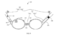
- a glasses-type information processingapparatus 500 according to another embodiment of the present invention further includes at least one storage battery module 502.
- the storage battery module 502 is set on a frame 501, and is configured to provide electrical energy to at least one display module 503, at least one camera module 505, at least one microphone module 507, and a processing module 509.
- Similar symbols such as 401 and 501 represent the same component, for example, a frame, which will not be described for brevity.
- the description of corresponding components in the foregoing embodiments may be referenced to for the detailed structure.
- the storage battery module 502 is an energy supplying apparatus in the glasses-type information processing apparatus 500 according to the embodiment of the present invention, and may be one of various energy storing apparatuses such as a micro battery, a rechargeable battery, and a bio-battery.
- the storage battery module 502 may further integrate a power management circuit for transferring the electrical energy stored in the storage battery module 502 to the foregoing modules as required, so as to achieve proper use of the electrical energy.
- a glasses-type information processing apparatus 500 further includes at least one electromagnetic induction coil module 504.
- the at least one electromagnetic induction coil module 504 is set on the frame 501, and is configured to obtain electrical energy in a manner of electromagnetic induction and store the obtained electrical energy in the storage battery module 502.
- a glasses-type information processing apparatus 500 further includes at least one solar panel 506.
- the solar panel 506 is set on the frame 501 to obtain solar energy, and convert the solar energy into electrical energy to recharge the storage battery module 502.
- the solar panel 506 according to the embodiment, preferentially, is transparent.
- the transparent solar panel may be made as lenses of the glasses.
- the solar panel lens may be planar, concave, or convex, so as to form a pair of glasses with degrees.
- the solar panel 506 may also be translucent and be colored to a certain extent, for example, a color of a pair of sunglasses.
- the solar panel 506 may also be opaque.
- the solar panel 506 may be fixed to the frame 501, where a preferential manner is to be connected movably, for example, by using a hinge connection. By using a movable connection, an angle of the solar panel 506 may be adjusted by rotating upside down. A rotatable solar panel helps to adjust the angle to be aligned to the sunlight to obtain solar energy. There may be one or four solar panels 506.
- a glasses-type information processing apparatus 500 further includes a display control module 508.
- the display control module 508 is set on the frame 501 and configured to control the display module 503 to emit a display laser.
- a glasses-type information processing apparatus 500 further includes a line-of-sight analyzing and processing module 510.
- the line-of-sight analyzing and processing module 510 is set on the frame, and is configured to analyze a user's pupil image taken by the camera module 505, and output focus information concerned by the user's line of sight.
- the processing module 509 is configured to receive the focus information output by the line-of-sight analyzing and processing module 510, and change, according to the focus information, data information output to the at least one display module 503, so that the at least one display apparatus displays a visual picture matching the focus concerned by the user's line of sight.
- the glasses-type information processing apparatus includes at least one display module, a communications module, a processing module, at least one camera module, and at least one microphone module, and the method includes:
- the microphone module or the display module receives destination address information of a destination location.
- a user enters destination address information or an address name. Specifically, the user may use the microphone module 104 to enter the address information or address name in a form of a voice instruction.
- the communications module, the processing module, or the at least camera module obtains location information of a current location of the glasses-type communications apparatus.
- the communications apparatus obtains the location information thereof. Specifically, the communications apparatus obtains the location information by using a GPS module thereof. Alternatively, the communications apparatus may communicate with a radio base station by using the communications module 102 to obtain the location information thereof.
- a processor obtains information about a path from the current location to the destination location according to the destination address information and the current location information.
- the communications apparatus calculates the information about the path. Specifically, by using map information, the communications apparatus calculates the path from the address information to the destination address by using the processing module. Alternatively, when calculating the path, the communications apparatus may consider path status information, where the path status information may be obtained by the communications module 102 from a network, so as to help the communications apparatus to obtain an optimal path by calculation.
- the display module displays the information about the path.
- the glasses-type information processing apparatus may be used to automatically obtain the location information thereof, obtain the path with reference to the destination address information entered by the user, and finally display the information about the path by using the display apparatus to the user, so as to implement a function of facilitating use of the user and releasing the user's hands.
- the obtaining, by the camera module, the location information of the current location of the glasses-type communications apparatus specifically includes: capturing, by the camera module, an image of an environment around the location of the glasses-type communications apparatus; and analyzing the acquired image of the environment around the location of the glasses-type communications apparatus, so as to obtain the location information of the current location of the glasses-type communications apparatus.
- the camera module 105 takes photos of the surrounding environment.
- the processing module analyzes the photos to calculate the location information thereof. For example, the camera module shoots a building or a signpost around the user wearing the glasses-type communications apparatus and forms a photo, and the processing module analyzes the photos to calculate the location information of the communications apparatus.
- the obtaining, by the processing module, the location information of the current location of the glasses-type communications apparatus specifically includes: obtaining GPS information of the glasses-type communications apparatus, and obtaining, by the processor, the location information of the current location of the glasses-type communications apparatus according to the GPS information.
- the obtaining, by the processor, information about a path from the current location to the destination location according to the destination address information and the current location information specifically includes: obtaining, by the processor, the information about the path from the current location to the destination location by performing calculation according to the destination address information and the current location information; or sending, by the processor, the destination address information and the current location information to a network server by using the communications module, and receiving, by using the communications module, the information about the path from the current location to the destination location that is calculated by the network server according to the destination address information and the current location information.
- the glasses-type communications system includes a projecting module, a display module, an image-acquiring module, a processing module, and a camera module, where the control method includes:
- FIG. 12 is a flowchart of a security verification method of a glasses-type communications apparatus according to an embodiment of the present invention. As shown in the figure:
- the collecting manner may be:
- a specific implementation manner includes:
- step 1260 Assign a corresponding right to the user. Specifically, assign a corresponding right to the user according to the matching result in step 1250, where the right includes a hardware use right, a data access right, a network access right, or the like.
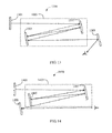
- FIG. 13 illustrates a display system with a variable optical path length according to another embodiment of the present invention.
- the display system 1300 with a variable optical path length includes an imaging unit 1301, an optical path length adjusting unit 1003, and a reflecting unit 1309.
- the optical path length adjusting unit 1303 is used to adjust an optical path length, and further includes a first optical path length increasing unit 1305 and a second optical path length increasing unit 1307.
- the reflecting unit 1309 is configured to reflect the image-displaying light going through the optical path length adjusting unit.
- the first optical path length increasing unit 1305 and the second optical path length increasing unit 1307 in the display system 1300 with a variable optical path length perform reflection for an even number of times: 2n.
- the imaging unit 1301 emits light in a direction different from an incident direction of a person's eyes.
- the optical path length adjusting unit 1303 may include multiple optical path length increasing units 1305/1307, where the optical path length increasing units 1305/1307 specifically are reflectors.
- the image-displaying light is reflected for at least 2+1 times on at least two optical path length increasing units 1305/1307. Further, a reflection angle of the at least 2+1 times reflection is smaller than 5 degrees, where the reflection may be performed for more times within a range smaller than 2 degrees, so as to further increase the optical path length.
- the optical path length adjusting unit 1303 increases the optical path length by reflecting the image-displaying light between the optical path length increasing units 1305/1307 for multiple times.
- the optical path length adjusting unit 1303 may include three configurations of a short optical path length, a medium optical path length, and a long optical path length, which respectively correspond to a short-distance displayed image, a medium-distance displayed image, and a long-distance displayed image.
- the optical path length adjusting unit 1303 includes two sub-optical path length adjusting units, where the two sub-optical path length adjusting units are any two of a long optical path length adjusting unit, a medium optical path length adjusting unit, and a short optical path length adjusting unit, and FIG. 15 may be referenced to for specific implementation.
- the display system 1400 with a variable optical path length includes an imaging unit 1401, an optical path length adjusting unit 1403, and a reflecting unit 1409.
- the optical path length adjusting unit 1403 is used to adjust an optical path length, and further includes a first optical path length increasing unit 1405 and a second optical path length increasing unit 1407. After image-displaying light emitted by the imaging unit goes through the optical path length adjusting unit 1403, an optical path length of the image-displaying light changes according to a setting of the optical path length adjusting unit.
- the reflecting unit 1409 is configured to reflect the image-displaying light going through the optical path length adjusting unit.
- the first optical path length increasing unit 1405 and the second optical path length increasing unit 1407 in the display system 1400 with a variable optical path length perform reflection for an odd number of times: 2n+1.
- the imaging unit 1401 and a person's eyes are located respectively on both sides of the optical path length adjusting unit 1403.
- the imaging unit 1401 emits light in a direction different from an incident direction of a person's eyes.
- the optical path length adjusting unit 1403 increases the optical path length by reflecting the image-displaying light between the optical path length increasing units 1405/1407 for multiple times.
- the optical path length adjusting unit 1403 may include three configurations of a short optical path length, a medium optical path length, and a long optical path length, which respectively correspond to a short-distance displayed image, a medium-distance displayed image, and a long-distance displayed image.
- the optical path length adjusting unit 1403 includes two sub-optical path length adjusting units, where the two optical path length adjusting units are any two of a long optical path length adjusting unit, a medium optical path length adjusting unit, and a short optical path length adjusting unit, and FIG. 15 may be referenced to for specific implementation.
- the display system 1500 with a variable optical path length includes an imaging unit 1501, an optical path length adjusting unit 1503, a reflecting unit 1509, a controlling unit 1510, and a detecting unit 1512.
- the optical path length adjusting unit 1503 is configured to adjust an optical path length, and further includes a first optical path length adjusting subunit 1504 and a second optical path length adjusting subunit 1506. After image-displaying light emitted by the imaging unit 1501 goes through the optical path length adjusting unit 1503, an optical path length of the image-displaying light changes according to a setting of the optical path length adjusting unit.
- the reflecting unit 1509 is configured to reflect the image-displaying light going through the optical path length adjusting unit.
- the two optical path length adjusting subunits 1504 and 1506 are any two of a long optical path length adjusting unit, a medium optical path length adjusting unit, and a short optical path length adjusting unit.
- the optical path length adjusting unit 1503 may also include multiple optical path length adjusting subunits.
- the detecting unit 1512 is configured to detect a size of a person's pupils, and calculate a vision distance of a current vision point of the person's eyes according to the size of the pupils.
- the controlling unit 1510 is configured to adjust the optical path length of the optical path length adjusting unit 1503 according to the vision distance of the current vision point of the person's eyes, which specifically is selecting the first optical path length adjusting subunit 1504 or the second optical path length adjusting subunit 1506 to operate according to the vision distance of the current vision point of the person's eyes.
- the display system 1600 with a variable optical path length includes an imaging unit 1601, an optical path length adjusting unit 1603, a reflecting unit 1609, a controlling unit 1610, and a detecting unit 1612.
- the optical path length adjusting unit 1603 is configured to adjust an optical path length, where FIG. 13 or FIG. 14 may be referenced to for specific implementation.
- the reflecting unit 1609 is configured to reflect the image-displaying light going through the optical path length adjusting unit.
- the optical path length adjusting unit 1603 includes any two of a long optical path length adjusting unit, a medium optical path length adjusting unit, and a short optical path length adjusting unit.
- the optical path length adjusting unit 1603 may also include multiple optical path length adjusting subunits.
- the detecting unit 1612 is configured to detect a size of a person's pupils, and calculate a vision distance of a current vision point of the person's eyes according to the size of the pupils.
- the controlling unit 1610 is configured to adjust the optical path length of the optical path length adjusting unit 103 according to the vision distance of the current vision point of the person's eyes, which specifically is selecting the first optical path length adjusting subunit or the second optical path length adjusting subunit to operate according to the vision distance of the current vision point of the person's eyes.
- the following provides a flowchart of a method for the display systems with a variable optical path length illustrated in FIG. 15 and FIG. 16 . As shown in FIG. 17 , the method includes the following steps:
- an image-acquiring apparatus is used to obtain a pupil image.
- the size of the pupils is obtained according to the pupil image, and then the vision distance of the current vision point of the people's eyes is estimated according to the size of the pupils.
- a specific manner of adjusting the optical path length of the optical path length adjusting unit includes selecting a first optical path length adjusting subunit or a second optical path length adjusting subunit in the optical path length adjusting unit to operate, or controlling image-displaying light to be reflected for more times in an optical path length increasing unit.
- the optical path length adjusting unit may be located inside a leg of a pair of glasses, or be set on a side of the leg of the pair of glasses.
- the reflecting units 609/709/809/909 usually are fixed reflecting units, where a change or adjustment thereof usually does not cause a change in the optical path length.
- the reflecting units 609/709/809/909 are semi-reflecting units for transmitting real light and reflecting light emitted by the imaging unit.
- the reflecting units 609/709/809/909 may include multiple reflecting units for reflecting image-displaying light for multiple times to enter a person's eyes from the front, so that the person's eyes generate vision.
- FIG. 18 is a schematic diagram of another glasses-type communications apparatus according to an embodiment of the present invention.
- An apparatus 1800 includes:
- the display module 1803 includes a display controlling unit 1803a, a laser emitting unit 1803b, and a reflecting lens 1803c.
- the display controlling unit 1083a receives a displayed content sent by a processing module 1809, and performs a processing operation to convert the displayed content into a control signal, so as to control the laser emitting unit 1803b to emit a display laser.
- the laser emitting unit 1803b is configured to emit the display laser under the control of the control signal of the display controlling unit 1803a, where the display laser is emitted in a manner of recycle scanning and is projected to the reflecting lens 1803c.
- the reflecting lens 1803c is configured to receive the scanning display laser emitted by the laser emitting unit 1803b, and project partial of the scanning display laser to a user's eyes in a manner of reflecting.
- the use's retina receives the display laser and senses the displayed content.
- the camera module 1805 is set on the frame 1801 and configured to take a photo or video.
- the communications module 1807 is set on the frame 1801, and is configured to provide communication between the apparatus and an external communications system.
- the module can provide communication with a wireless communications network or a wired communications network, so as to implement communication of content such as voice and data between the apparatus and the external communications network.
- the processing module 1809 is set on the frame 1801, and is mainly configured to perform calculation and processing on various images and videos, for example, image, video, or audio encoding and decoding, and image rendering, which may further include other data technical processing, such as speech recognition, image recognition, and the like.
- another glasses-type communications apparatus 1900 based on the glasses-type communications apparatus 1800 according to the embodiment of the present invention further includes:
- FIG. 20 is a schematic diagram of a glasses-type apparatus 2000 for monitoring a user's health indicators and exercise condition according to an embodiment of the present invention. As shown in the figure, an apparatus 2000 includes:
- a method 2100 for displaying a user's health information by using a glasses-type communications apparatus 2000 includes:
- the state sensor 2013 may be used to obtain health indicators by measuring a contact resistance with a person's head skin or by capturing a biological micro-electrical signal, or the exercise state signal may be obtained by sensing a change in a person's location, exercise speed, and exercise angle.
- the health indicators and the person's exercise state signal are obtained by using the state sensor 2013, and are transferred to the processor module 2009 for analyzing data, which may be compared with basic historical statistics data to calculate data of a change in the user's current health indicators and exercise state.
- the processor module 2009 after completing analysis of the data, sends the data to the display module 2003 to display the data of a change in the user's current health indicators and exercise state.
- a method for displaying a user's health information by using a glasses-type communications apparatus 2000 includes:
- the state sensor 2013 may be used to obtain health indicators by measuring a contact resistance with a person's head skin or by capturing a biological micro-electrical signal, or the exercise state signal may be obtained by sensing a change in a person's location, exercise speed, and exercise angle.
- the health indicators and the person's exercise state signal are obtained by using the state sensor 2013, and are transferred to the processor module 2009 for analyzing data, which may be compared with basic historical statistics data to calculate data of a change in the user's current health indicators and exercise state.
- the data of the user's current health indicators and exercise state that is calculated by the processor module 2009 is transmitted to the cloud memory by using the communications module 2007.
- the data of a change in the user's health indicators and exercise state is obtained by the communications module 2007 from the cloud memory, and sent to the display module 2003 to display the data of a change in the user's current health indicators and exercise state.
- FIG. 23 shows a specific display picture for displaying a health index and exercise state after the foregoing method is implemented.
- FIG. 24 illustrates a glasses-type communications system 2400 according to an embodiment of the present invention.
- the system 2400 includes a glasses-type communications apparatus 2410 and an external apparatus 2420.
- the communications apparatus 2410 has at least one communications module 2411 and at least one display apparatus module 2413 for communicating with the external apparatus 2420.
- the communication manner may be a wireless or wired manner.
- the wireless manner may be a manner such as Wi-Fi, Zigbee , Bluetooth, or Wireless HDMI.
- the display apparatus module 2413 may be used to synchronously display a picture of the external apparatus 2420.
- the external apparatus 2420 may be a mobile communications device such as a mobile phone or a Pad. A user may adjust the external apparatus 2420 to obtain a desired interface in advance as required, and then synchronize the picture to the communications apparatus 2410 for displaying by using the display module 2413, so as to release the hands.
- the glasses-type communications apparatus 2410 further includes a microphone module 2415, configured to receive the user's speech instruction, and transfer voice information to the external apparatus 2420 by using the communications module 2411.
- the external apparatus 2420 includes a speech recognition module 2421, where the speech recognition module 2421 is configured to perform speech recognition and analysis on the voice information received by the external apparatus 2420.
- the external apparatus 2420 makes a corresponding response according to the speech recognition and analysis result.
- the external apparatus 2420 includes: a processor module 2423, configured to process data information related to the glasses-type communications apparatus 2410, where the processor module 2423 may be used to perform operations, such as video compression and decompression, voice encoding and decoding, and image rendering and enhancement, on the data information related to the glasses-type communications apparatus 2410; and a network connection module 2425, configured to communicate with the Internet or a radio communications system to provide network access for a user; a communications module 2427 for the external apparatus 2420 to communicate with the glasses-type communications apparatus 2410; and a picture controlling module 2429, configured to control to switch/synchronize a picture to the glasses-type communications apparatus 2410 and display the picture on the display apparatus module 2413.
- a processor module 2423 configured to process data information related to the glasses-type communications apparatus 2410, where the processor module 2423 may be used to perform operations, such as video compression and decompression, voice encoding and decoding, and image rendering and enhancement, on the data information related to the glasses-type communications apparatus 2410
- another glasses-type communications system 2500 includes: a glasses-type communications apparatus 2510, where the glasses-type communications apparatus 2510 includes at least one projecting module 2511, a display module 2513, a communications module 2515, and a processing module 2517.
- the projecting module 2511 projects content displayed in the display module 2513 onto a plane a.
- the glasses-type communications apparatus 2510 further includes a camera module 2519, configured to take a new image after an operation is performed on a projected image, and send the new image to a background or a cloud apparatus 2520.
- the cloud or background performs image processing, calculates an operation instruction, and makes a response.
- processing on the image taken by the camera module 2519 may be performed locally on the glasses-type communications apparatus 2510, where the processing module 2517 on the communications apparatus 2510 is used to perform corresponding processing and make a response; alternatively and simply, the communications module 2515 may be used to transfer the image to the external apparatus 2530, where the processing module 2531 in the external apparatus 2530 performs processing and makes a response, where information about the response may be transferred to the glasses-type communications apparatus by using the communications module 2533 of the external apparatus 2530.
Landscapes
- Engineering & Computer Science (AREA)
- Signal Processing (AREA)
- Computer Networks & Wireless Communication (AREA)
- Physics & Mathematics (AREA)
- General Physics & Mathematics (AREA)
- Optics & Photonics (AREA)
- User Interface Of Digital Computer (AREA)
- Controls And Circuits For Display Device (AREA)
- Telephone Function (AREA)
- Testing, Inspecting, Measuring Of Stereoscopic Televisions And Televisions (AREA)
Priority Applications (1)
| Application Number | Priority Date | Filing Date | Title |
|---|---|---|---|
| EP17151652.9A EP3249443B1 (de) | 2012-12-22 | 2013-08-07 | Brillenartige informationsverarbeitungsvorrichtung, system, verfahren |
Applications Claiming Priority (2)
| Application Number | Priority Date | Filing Date | Title |
|---|---|---|---|
| CN201210563136.4A CN103888163A (zh) | 2012-12-22 | 2012-12-22 | 一种眼镜式通信装置、系统及方法 |
| PCT/CN2013/080960 WO2014094439A1 (zh) | 2012-12-22 | 2013-08-07 | 一种眼镜式通信装置、系统及方法 |
Related Child Applications (2)
| Application Number | Title | Priority Date | Filing Date |
|---|---|---|---|
| EP17151652.9A Division-Into EP3249443B1 (de) | 2012-12-22 | 2013-08-07 | Brillenartige informationsverarbeitungsvorrichtung, system, verfahren |
| EP17151652.9A Division EP3249443B1 (de) | 2012-12-22 | 2013-08-07 | Brillenartige informationsverarbeitungsvorrichtung, system, verfahren |
Publications (3)
| Publication Number | Publication Date |
|---|---|
| EP2800281A1 true EP2800281A1 (de) | 2014-11-05 |
| EP2800281A4 EP2800281A4 (de) | 2015-03-25 |
| EP2800281B1 EP2800281B1 (de) | 2017-05-17 |
Family
ID=50956901
Family Applications (2)
| Application Number | Title | Priority Date | Filing Date |
|---|---|---|---|
| EP13863962.0A Active EP2800281B1 (de) | 2012-12-22 | 2013-08-07 | Kommunikationsvorrichtung in brillenform sowie system und verfahren dafür |
| EP17151652.9A Active EP3249443B1 (de) | 2012-12-22 | 2013-08-07 | Brillenartige informationsverarbeitungsvorrichtung, system, verfahren |
Family Applications After (1)
| Application Number | Title | Priority Date | Filing Date |
|---|---|---|---|
| EP17151652.9A Active EP3249443B1 (de) | 2012-12-22 | 2013-08-07 | Brillenartige informationsverarbeitungsvorrichtung, system, verfahren |
Country Status (5)
| Country | Link |
|---|---|
| US (2) | US9100097B2 (de) |
| EP (2) | EP2800281B1 (de) |
| CN (9) | CN105141331B (de) |
| ES (1) | ES2631684T3 (de) |
| WO (1) | WO2014094439A1 (de) |
Families Citing this family (45)
| Publication number | Priority date | Publication date | Assignee | Title |
|---|---|---|---|---|
| US20160019715A1 (en) * | 2014-07-15 | 2016-01-21 | Osterhout Group, Inc. | Content presentation in head worn computing |
| EP3149960A4 (de) | 2014-05-26 | 2018-01-24 | Vladimir Sherman | Verfahren, schaltvorrichtungen, systeme und zugehöriger computerausführbarer code zur erfassung von akustischen signalen |
| CN105759420A (zh) * | 2014-12-18 | 2016-07-13 | 上海市格致中学 | 百度眼镜 |
| CN104639965A (zh) * | 2015-02-10 | 2015-05-20 | 云晖软件(成都)有限公司 | 一种飞行器娱乐可视化系统 |
| US10878775B2 (en) * | 2015-02-17 | 2020-12-29 | Mentor Acquisition One, Llc | See-through computer display systems |
| CN104750448A (zh) * | 2015-03-23 | 2015-07-01 | 联想(北京)有限公司 | 一种信息处理的方法、电子设备及可穿戴设备 |
| CN104808800A (zh) * | 2015-05-21 | 2015-07-29 | 上海斐讯数据通信技术有限公司 | 智能眼镜设备、移动终端及移动终端操作方法 |
| CN105157747B (zh) * | 2015-07-16 | 2016-07-06 | 福建省亿鑫海信息科技有限公司 | 一种各部件分离的检测系统及检测方法 |
| CN105007424A (zh) * | 2015-07-22 | 2015-10-28 | 深圳市万姓宗祠网络科技股份有限公司 | 一种基于眼球跟踪的自动对焦系统、方法及其可穿戴设备 |
| WO2017049072A1 (en) | 2015-09-16 | 2017-03-23 | Blum Ronald D | Systems, apparatus, and methods for ophthalmic lenses with wireless charging |
| CN105167423A (zh) * | 2015-10-23 | 2015-12-23 | 王贝 | 一种智能书柜及其使用方法 |
| CN105231686A (zh) * | 2015-10-27 | 2016-01-13 | 翟小艳 | 一种能通过眼镜控制的书柜及其工作方法 |
| CN105892634A (zh) * | 2015-11-18 | 2016-08-24 | 乐视致新电子科技(天津)有限公司 | 防眩晕方法及虚拟现实显示输出设备 |
| US9979930B2 (en) * | 2015-12-03 | 2018-05-22 | Beijing Pico Technology Co., Ltd. | Head-wearable apparatus, 3D video call system and method for implementing 3D video call |
| CN106888350A (zh) * | 2015-12-15 | 2017-06-23 | 北京奇虎科技有限公司 | 基于智能眼镜的拍照处理方法、智能眼镜和用户终端 |
| WO2017114759A1 (fr) * | 2015-12-30 | 2017-07-06 | Essilor International (Compagnie Generale D'optique) | Procédé de commande d'un système ophtalmique à partir d'une mesure et d'une information obtenue par un dispositif électronique externe |
| EP3400478B1 (de) | 2016-01-07 | 2023-08-16 | Magic Leap, Inc. | Systeme und verfahren für virtuelle und erweiterte realitäten mit ungleicher zahl von über tiefenebenen verteilten komponentenfarbbildern |
| US12149591B2 (en) | 2016-01-25 | 2024-11-19 | Hiscene Information Technology Co., Ltd | Method and apparatus for augmented reality interaction and presentation |
| CN106997235B (zh) * | 2016-01-25 | 2018-07-13 | 亮风台(上海)信息科技有限公司 | 用于实现增强现实交互和展示的方法、设备 |
| CN105744293B (zh) * | 2016-03-16 | 2019-04-16 | 北京小米移动软件有限公司 | 视频直播的方法及装置 |
| CN107621696A (zh) * | 2016-07-15 | 2018-01-23 | 上海翊视皓瞳信息科技有限公司 | 一种用于视觉增强的智能眼镜 |
| CN106343955A (zh) * | 2016-08-26 | 2017-01-25 | 深圳市沃特沃德股份有限公司 | 终端及宠物是否健康的判断方法和装置 |
| CN106406445B (zh) * | 2016-09-09 | 2020-01-14 | 华南理工大学 | 基于智能眼镜的视障辅助中文文本阅读系统 |
| CN106707512B (zh) * | 2016-12-26 | 2023-10-27 | 中科海微(北京)科技有限公司 | 一种低功耗智能ar系统及智能ar眼镜 |
| CN106526863B (zh) * | 2017-01-03 | 2019-10-01 | 京东方科技集团股份有限公司 | 一种眼镜 |
| CN107167147A (zh) * | 2017-05-02 | 2017-09-15 | 深圳市元征科技股份有限公司 | 基于窄带物联网的导航方法、眼镜及可读存储介质 |
| CN107085316A (zh) * | 2017-06-30 | 2017-08-22 | 京东方科技集团股份有限公司 | 液晶镜片和液晶眼镜 |
| CN108303972B (zh) * | 2017-10-31 | 2020-01-17 | 腾讯科技(深圳)有限公司 | 移动机器人的交互方法及装置 |
| CN107748453A (zh) * | 2017-11-29 | 2018-03-02 | 常州机电职业技术学院 | 一种大数据背景下的智能眼镜 |
| JP6847885B2 (ja) * | 2018-03-20 | 2021-03-24 | 株式会社東芝 | 情報処理装置、情報処理方法及びプログラム |
| US20200166782A1 (en) * | 2018-11-27 | 2020-05-28 | Tsai-Tzu LIAO | Optical photographic glasses |
| CN109859717A (zh) * | 2018-12-26 | 2019-06-07 | 李星辉 | 一种防远光眼镜及控制方法 |
| CN111856750B (zh) * | 2019-04-26 | 2022-01-14 | 华为技术有限公司 | 鼻托组件及头戴式显示设备 |
| CN110244837A (zh) * | 2019-04-26 | 2019-09-17 | 北京圣威特科技有限公司 | 增强现实且具有虚拟影像叠加的体验眼镜及其成像方法 |
| CN112346243B (zh) * | 2019-08-08 | 2022-11-29 | Oppo广东移动通信有限公司 | 一种眼镜 |
| CN110515221A (zh) * | 2019-10-16 | 2019-11-29 | 深圳市思坦科技有限公司 | 一种信息显示眼镜及其制作方法 |
| CN111190289B (zh) * | 2019-12-10 | 2022-01-07 | 山东新文化传媒科技股份有限公司 | 一种头戴式vr智能设备及其佩戴方法 |
| US11533443B2 (en) * | 2020-06-29 | 2022-12-20 | Innovega, Inc. | Display eyewear with adjustable camera direction |
| CN112399167B (zh) * | 2020-12-08 | 2021-04-13 | 恒玄科技(北京)有限公司 | 一种用于无线通信的智能眼镜 |
| CN113189798A (zh) * | 2021-05-11 | 2021-07-30 | Tcl通讯(宁波)有限公司 | 一种智能眼镜设备及智能眼镜设备控制方法 |
| CN215340585U (zh) * | 2021-05-17 | 2021-12-28 | 深圳市英士慷科技有限公司 | 一种射击降噪视频眼镜 |
| CN115458521B (zh) | 2021-05-21 | 2026-04-10 | 联华电子股份有限公司 | 微发光二极管布局结构及其制作方法 |
| CN113792724B (zh) * | 2021-09-27 | 2024-03-26 | 山东新一代信息产业技术研究院有限公司 | 一种助老眼镜的使用方法及设备 |
| CN114420131B (zh) * | 2022-03-16 | 2022-05-31 | 云天智能信息(深圳)有限公司 | 低弱视力智能语音辅助识别系统 |
| US20250306370A1 (en) * | 2024-04-01 | 2025-10-02 | Jermaine Townes | Wireless Virtual Reality Headset Device |
Family Cites Families (49)
| Publication number | Priority date | Publication date | Assignee | Title |
|---|---|---|---|---|
| WO1999023524A1 (en) * | 1997-10-30 | 1999-05-14 | The Microoptical Corporation | Eyeglass interface system |
| JP3825222B2 (ja) * | 2000-03-24 | 2006-09-27 | 松下電器産業株式会社 | 本人認証装置および本人認証システムならびに電子決済システム |
| JP2002318365A (ja) * | 2001-04-20 | 2002-10-31 | Sanyo Electric Co Ltd | 網膜投影型ディスプレイ |
| JP2004061960A (ja) * | 2002-07-30 | 2004-02-26 | Canon Inc | 投射型画像表示装置および画像表示システム |
| CN1856728A (zh) * | 2003-08-15 | 2006-11-01 | 易维视公司 | 增强电活性透镜系统 |
| CN100367074C (zh) * | 2003-10-27 | 2008-02-06 | 深圳国际技术创新研究院 | 眼镜式显示器 |
| US20050088572A1 (en) * | 2003-10-28 | 2005-04-28 | Pandit Amol S. | System and method for a camera docking station |
| KR100607989B1 (ko) | 2004-06-28 | 2006-08-02 | 삼성전자주식회사 | 어레이 미러를 구비한 반사부 유닛 및 이를 채용한프로젝션 디스플레이 시스템 |
| CN2798135Y (zh) * | 2005-01-10 | 2006-07-19 | 捷飞科研有限公司 | 监测生理系统参数的眼镜 |
| CN1815437A (zh) * | 2005-02-04 | 2006-08-09 | 乐金电子(中国)研究开发中心有限公司 | 一种外置头戴式手机显示装置及方法 |
| CN101198277B (zh) * | 2005-02-22 | 2011-06-15 | 海尔思-斯玛特有限公司 | 用于生理学和心理生理学监控的系统 |
| CN1985751B (zh) * | 2005-12-21 | 2010-05-05 | 香港理工大学 | 佩戴式生理体征检测器、生理体征遥测和警报系统 |
| CN1991304B (zh) * | 2005-12-30 | 2011-03-16 | 财团法人工业技术研究院 | 具有导航功能的生理感测装置 |
| JP2008165063A (ja) * | 2006-12-28 | 2008-07-17 | Scalar Corp | ヘッドマウントディスプレイ |
| EP2165234A1 (de) * | 2007-06-07 | 2010-03-24 | Panagiotis Pavlopoulos | Brille mit mindestens einer displayanordnung |
| WO2009041055A1 (ja) * | 2007-09-26 | 2009-04-02 | Panasonic Corporation | ビーム走査型表示装置、その表示方法、プログラム、及び集積回路 |
| CN101424787B (zh) * | 2007-10-29 | 2011-07-27 | 吕兴增 | 半反射及折射光学效应组合光学应用的虚像显示装置 |
| WO2009153967A1 (ja) | 2008-06-17 | 2009-12-23 | パナソニック株式会社 | サーバ装置、サーバ処理方法およびプログラム |
| CN201230347Y (zh) * | 2008-06-27 | 2009-04-29 | 天津三星电子有限公司 | 带有虹膜识别系统的数码摄像机 |
| CN201299554Y (zh) * | 2008-07-30 | 2009-09-02 | 深圳先进技术研究院 | 一种运动和生理信息检测设备 |
| CN201242611Y (zh) * | 2008-08-12 | 2009-05-20 | 贾怀昌 | 自由曲面全反射式的目视光学棱镜 |
| US20100091094A1 (en) * | 2008-10-14 | 2010-04-15 | Marek Sekowski | Mechanism for Directing a Three-Dimensional Camera System |
| WO2010062481A1 (en) | 2008-11-02 | 2010-06-03 | David Chaum | Near to eye display system and appliance |
| CN201341167Y (zh) * | 2009-01-13 | 2009-11-04 | 福建大兆电子科技有限公司 | 无线电子通讯多媒体眼镜 |
| CN100595635C (zh) * | 2009-01-14 | 2010-03-24 | 长春大学 | 智能盲人导航眼镜 |
| US8105208B2 (en) * | 2009-05-18 | 2012-01-31 | Adidas Ag | Portable fitness monitoring systems with displays and applications thereof |
| CN101612032A (zh) * | 2009-07-31 | 2009-12-30 | 中国科学院光电技术研究所 | 一种基于双压电片变形镜的自适应光学视网膜成像系统 |
| CN101615168A (zh) | 2009-08-04 | 2009-12-30 | 上海华勤通讯技术有限公司 | 利用电脑处理移动终端数据的系统及其实现方法 |
| CN201494401U (zh) * | 2009-08-07 | 2010-06-02 | 成都合纵连横资产经营管理咨询有限公司 | 一种汽车安全防盗系统 |
| US20110214082A1 (en) * | 2010-02-28 | 2011-09-01 | Osterhout Group, Inc. | Projection triggering through an external marker in an augmented reality eyepiece |
| AU2011220382A1 (en) * | 2010-02-28 | 2012-10-18 | Microsoft Corporation | Local advertising content on an interactive head-mounted eyepiece |
| CN102783186A (zh) * | 2010-03-10 | 2012-11-14 | 托马斯·M·利卡兹 | 通信眼镜组件 |
| CN201657179U (zh) * | 2010-03-22 | 2010-11-24 | 深圳市祈锦通信技术有限公司 | 一种投影装置及移动终端 |
| CN101819334B (zh) * | 2010-04-01 | 2013-04-17 | 夏翔 | 多功能电子眼镜 |
| US20110307842A1 (en) * | 2010-06-14 | 2011-12-15 | I-Jen Chiang | Electronic reading device |
| CN101893934A (zh) * | 2010-06-25 | 2010-11-24 | 宇龙计算机通信科技(深圳)有限公司 | 一种智能调整屏幕显示的方法和装置 |
| CN102314731A (zh) * | 2010-07-06 | 2012-01-11 | 中国银联股份有限公司 | 移动支付方法和用于实现该移动支付方法的设备 |
| CN201903695U (zh) * | 2010-08-31 | 2011-07-20 | 夏翔 | 无线物联网眼镜 |
| JP2012069023A (ja) * | 2010-09-27 | 2012-04-05 | Hitachi Ltd | 異常検知装置 |
| CN102062946A (zh) * | 2010-11-05 | 2011-05-18 | 鸿富锦精密工业(深圳)有限公司 | 具有通信功能的眼镜式显示装置 |
| CN102026346B (zh) | 2010-12-15 | 2014-12-10 | 中兴通讯股份有限公司 | 一种移动终端及其计算方法 |
| US20120200793A1 (en) * | 2011-01-31 | 2012-08-09 | Hossein Tajalli Tehrani | 3-D Cinema and Display Technology |
| US10083639B2 (en) * | 2011-02-04 | 2018-09-25 | Seiko Epson Corporation | Control device for controlling image display device, head-mounted display device, image display system, control method for the image display device, and control method for the head-mounted display device |
| CN202057915U (zh) * | 2011-05-09 | 2011-11-30 | 无锡爱睿芯电子有限公司 | 一种导航眼镜 |
| US9285592B2 (en) * | 2011-08-18 | 2016-03-15 | Google Inc. | Wearable device with input and output structures |
| CN102496007B (zh) * | 2011-12-02 | 2014-06-11 | 陈中山 | 人体身份识别仪 |
| CN202600565U (zh) * | 2012-03-29 | 2012-12-12 | 魏鹏 | 眼镜式智能终端 |
| US20130307855A1 (en) * | 2012-05-16 | 2013-11-21 | Mathew J. Lamb | Holographic story telling |
| CN102813574B (zh) * | 2012-08-03 | 2014-09-10 | 上海交通大学 | 基于眼动跟踪的视觉假体图像采集装置 |
-
2012
- 2012-12-22 CN CN201510601205.XA patent/CN105141331B/zh active Active
- 2012-12-22 CN CN201510600926.9A patent/CN105162482A/zh active Pending
- 2012-12-22 CN CN201510600945.1A patent/CN105208333B/zh active Active
- 2012-12-22 CN CN201510600599.7A patent/CN105163268B/zh active Active
- 2012-12-22 CN CN201510600524.9A patent/CN105306082B/zh active Active
- 2012-12-22 CN CN201510601002.0A patent/CN105120424B/zh active Active
- 2012-12-22 CN CN201510601004.XA patent/CN105262497A/zh active Pending
- 2012-12-22 CN CN201210563136.4A patent/CN103888163A/zh active Pending
- 2012-12-22 CN CN201510601059.0A patent/CN105120441A/zh active Pending
-
2013
- 2013-08-07 WO PCT/CN2013/080960 patent/WO2014094439A1/zh not_active Ceased
- 2013-08-07 EP EP13863962.0A patent/EP2800281B1/de active Active
- 2013-08-07 EP EP17151652.9A patent/EP3249443B1/de active Active
- 2013-08-07 ES ES13863962.0T patent/ES2631684T3/es active Active
-
2014
- 2014-08-22 US US14/466,287 patent/US9100097B2/en active Active
-
2015
- 2015-06-24 US US14/748,762 patent/US9813095B2/en active Active
Also Published As
| Publication number | Publication date |
|---|---|
| CN105163268B (zh) | 2020-03-10 |
| ES2631684T3 (es) | 2017-09-04 |
| EP2800281B1 (de) | 2017-05-17 |
| US9813095B2 (en) | 2017-11-07 |
| CN105208333A (zh) | 2015-12-30 |
| CN105208333B (zh) | 2019-05-10 |
| CN105306082A (zh) | 2016-02-03 |
| US20150295610A1 (en) | 2015-10-15 |
| CN105141331A (zh) | 2015-12-09 |
| CN105141331B (zh) | 2019-08-27 |
| CN105120424A (zh) | 2015-12-02 |
| CN105163268A (zh) | 2015-12-16 |
| CN105262497A (zh) | 2016-01-20 |
| US9100097B2 (en) | 2015-08-04 |
| EP3249443A3 (de) | 2018-04-18 |
| CN105120424B (zh) | 2020-02-14 |
| CN103888163A (zh) | 2014-06-25 |
| CN105162482A (zh) | 2015-12-16 |
| US20140376491A1 (en) | 2014-12-25 |
| EP2800281A4 (de) | 2015-03-25 |
| CN105306082B (zh) | 2018-10-30 |
| CN105120441A (zh) | 2015-12-02 |
| EP3249443A2 (de) | 2017-11-29 |
| EP3249443B1 (de) | 2021-06-30 |
| WO2014094439A1 (zh) | 2014-06-26 |
Similar Documents
| Publication | Publication Date | Title |
|---|---|---|
| EP2800281B1 (de) | Kommunikationsvorrichtung in brillenform sowie system und verfahren dafür | |
| US9245389B2 (en) | Information processing apparatus and recording medium | |
| CN105334864B (zh) | 一种用于控制无人机的智能眼镜及控制方法 | |
| KR102321362B1 (ko) | 헤드 마운트 디스플레이 디바이스가 영상을 디스플레이하는 방법 및 그 헤드 마운트 디스플레이 디바이스 | |
| US20160165220A1 (en) | Display apparatus and method of controlling display apparatus | |
| CN105340279A (zh) | 用于近眼显示器的显示更新时间缩减 | |
| CN105137601B (zh) | 一种智能眼镜 | |
| JP2015005972A (ja) | 撮影画像のプライバシー保護機能を有するウェアラブルデバイス及びその制御方法並びに画像共有システム | |
| CN105319716A (zh) | 显示装置、显示装置的控制方法及程序 | |
| US9319980B1 (en) | Efficient digital image distribution | |
| CN104865704B (zh) | 一种基于移动设备的透射式与非透射式可切换头戴设备 | |
| US9588344B2 (en) | Head-mount display with exercise information displayed thereon | |
| WO2016101861A1 (zh) | 头戴式显示装置 | |
| JP2018018315A (ja) | 表示システム、表示装置、情報表示方法、及び、プログラム | |
| US20160189341A1 (en) | Systems and methods for magnifying the appearance of an image on a mobile device screen using eyewear | |
| CN104062758B (zh) | 图像显示的方法和显示设备 | |
| CN104239877B (zh) | 图像处理的方法和图像采集设备 | |
| KR101862381B1 (ko) | 사용자의 양안의 초점에 부합하는 영상제공 휴대단말장치 | |
| JP2020201723A (ja) | 画像処理装置、ウェアラブルデバイス、画像処理プログラム、画像処理方法、オブジェクト認識装置、オブジェクト認識プログラムおよびオブジェクト認識方法 | |
| KR20160097785A (ko) | 글래스 타입 단말기 및 그 제어 방법 | |
| CN106303467B (zh) | 一种智能穿戴设备及数据传输方法 | |
| JP2016085634A (ja) | 表示装置、表示装置の制御方法、及び、プログラム |
Legal Events
| Date | Code | Title | Description |
|---|---|---|---|
| PUAI | Public reference made under article 153(3) epc to a published international application that has entered the european phase |
Free format text: ORIGINAL CODE: 0009012 |
|
| 17P | Request for examination filed |
Effective date: 20140728 |
|
| AK | Designated contracting states |
Kind code of ref document: A1 Designated state(s): AL AT BE BG CH CY CZ DE DK EE ES FI FR GB GR HR HU IE IS IT LI LT LU LV MC MK MT NL NO PL PT RO RS SE SI SK SM TR |
|
| RIC1 | Information provided on ipc code assigned before grant |
Ipc: H04B 1/38 20150101AFI20150209BHEP |
|
| A4 | Supplementary search report drawn up and despatched |
Effective date: 20150219 |
|
| RIC1 | Information provided on ipc code assigned before grant |
Ipc: H04B 1/38 20150101AFI20150213BHEP |
|
| DAX | Request for extension of the european patent (deleted) | ||
| 17Q | First examination report despatched |
Effective date: 20160502 |
|
| GRAP | Despatch of communication of intention to grant a patent |
Free format text: ORIGINAL CODE: EPIDOSNIGR1 |
|
| INTG | Intention to grant announced |
Effective date: 20161014 |
|
| GRAS | Grant fee paid |
Free format text: ORIGINAL CODE: EPIDOSNIGR3 |
|
| STAA | Information on the status of an ep patent application or granted ep patent |
Free format text: STATUS: GRANT OF PATENT IS INTENDED |
|
| GRAJ | Information related to disapproval of communication of intention to grant by the applicant or resumption of examination proceedings by the epo deleted |
Free format text: ORIGINAL CODE: EPIDOSDIGR1 |
|
| GRAL | Information related to payment of fee for publishing/printing deleted |
Free format text: ORIGINAL CODE: EPIDOSDIGR3 |
|
| STAA | Information on the status of an ep patent application or granted ep patent |
Free format text: STATUS: EXAMINATION IS IN PROGRESS |
|
| REG | Reference to a national code |
Ref country code: DE Ref legal event code: R079 Ref document number: 602013021436 Country of ref document: DE Free format text: PREVIOUS MAIN CLASS: H04B0001380000 Ipc: H04B0001382700 |
|
| GRAR | Information related to intention to grant a patent recorded |
Free format text: ORIGINAL CODE: EPIDOSNIGR71 |
|
| STAA | Information on the status of an ep patent application or granted ep patent |
Free format text: STATUS: GRANT OF PATENT IS INTENDED |
|
| INTC | Intention to grant announced (deleted) | ||
| RIC1 | Information provided on ipc code assigned before grant |
Ipc: H04B 1/3827 20150101AFI20170307BHEP |
|
| GRAA | (expected) grant |
Free format text: ORIGINAL CODE: 0009210 |
|
| STAA | Information on the status of an ep patent application or granted ep patent |
Free format text: STATUS: THE PATENT HAS BEEN GRANTED |
|
| INTG | Intention to grant announced |
Effective date: 20170313 |
|
| AK | Designated contracting states |
Kind code of ref document: B1 Designated state(s): AL AT BE BG CH CY CZ DE DK EE ES FI FR GB GR HR HU IE IS IT LI LT LU LV MC MK MT NL NO PL PT RO RS SE SI SK SM TR |
|
| REG | Reference to a national code |
Ref country code: GB Ref legal event code: FG4D |
|
| REG | Reference to a national code |
Ref country code: CH Ref legal event code: EP |
|
| REG | Reference to a national code |
Ref country code: IE Ref legal event code: FG4D |
|
| REG | Reference to a national code |
Ref country code: AT Ref legal event code: REF Ref document number: 895297 Country of ref document: AT Kind code of ref document: T Effective date: 20170615 |
|
| REG | Reference to a national code |
Ref country code: DE Ref legal event code: R096 Ref document number: 602013021436 Country of ref document: DE |
|
| REG | Reference to a national code |
Ref country code: FR Ref legal event code: PLFP Year of fee payment: 5 |
|
| REG | Reference to a national code |
Ref country code: NL Ref legal event code: FP |
|
| REG | Reference to a national code |
Ref country code: SE Ref legal event code: TRGR |
|
| REG | Reference to a national code |
Ref country code: ES Ref legal event code: FG2A Ref document number: 2631684 Country of ref document: ES Kind code of ref document: T3 Effective date: 20170904 |
|
| REG | Reference to a national code |
Ref country code: LT Ref legal event code: MG4D |
|
| REG | Reference to a national code |
Ref country code: AT Ref legal event code: MK05 Ref document number: 895297 Country of ref document: AT Kind code of ref document: T Effective date: 20170517 |
|
| PG25 | Lapsed in a contracting state [announced via postgrant information from national office to epo] |
Ref country code: LT Free format text: LAPSE BECAUSE OF FAILURE TO SUBMIT A TRANSLATION OF THE DESCRIPTION OR TO PAY THE FEE WITHIN THE PRESCRIBED TIME-LIMIT Effective date: 20170517 Ref country code: AT Free format text: LAPSE BECAUSE OF FAILURE TO SUBMIT A TRANSLATION OF THE DESCRIPTION OR TO PAY THE FEE WITHIN THE PRESCRIBED TIME-LIMIT Effective date: 20170517 Ref country code: GR Free format text: LAPSE BECAUSE OF FAILURE TO SUBMIT A TRANSLATION OF THE DESCRIPTION OR TO PAY THE FEE WITHIN THE PRESCRIBED TIME-LIMIT Effective date: 20170818 Ref country code: NO Free format text: LAPSE BECAUSE OF FAILURE TO SUBMIT A TRANSLATION OF THE DESCRIPTION OR TO PAY THE FEE WITHIN THE PRESCRIBED TIME-LIMIT Effective date: 20170817 Ref country code: HR Free format text: LAPSE BECAUSE OF FAILURE TO SUBMIT A TRANSLATION OF THE DESCRIPTION OR TO PAY THE FEE WITHIN THE PRESCRIBED TIME-LIMIT Effective date: 20170517 |
|
| PG25 | Lapsed in a contracting state [announced via postgrant information from national office to epo] |
Ref country code: BG Free format text: LAPSE BECAUSE OF FAILURE TO SUBMIT A TRANSLATION OF THE DESCRIPTION OR TO PAY THE FEE WITHIN THE PRESCRIBED TIME-LIMIT Effective date: 20170817 Ref country code: LV Free format text: LAPSE BECAUSE OF FAILURE TO SUBMIT A TRANSLATION OF THE DESCRIPTION OR TO PAY THE FEE WITHIN THE PRESCRIBED TIME-LIMIT Effective date: 20170517 Ref country code: PL Free format text: LAPSE BECAUSE OF FAILURE TO SUBMIT A TRANSLATION OF THE DESCRIPTION OR TO PAY THE FEE WITHIN THE PRESCRIBED TIME-LIMIT Effective date: 20170517 Ref country code: IS Free format text: LAPSE BECAUSE OF FAILURE TO SUBMIT A TRANSLATION OF THE DESCRIPTION OR TO PAY THE FEE WITHIN THE PRESCRIBED TIME-LIMIT Effective date: 20170917 Ref country code: RS Free format text: LAPSE BECAUSE OF FAILURE TO SUBMIT A TRANSLATION OF THE DESCRIPTION OR TO PAY THE FEE WITHIN THE PRESCRIBED TIME-LIMIT Effective date: 20170517 |
|
| PG25 | Lapsed in a contracting state [announced via postgrant information from national office to epo] |
Ref country code: CZ Free format text: LAPSE BECAUSE OF FAILURE TO SUBMIT A TRANSLATION OF THE DESCRIPTION OR TO PAY THE FEE WITHIN THE PRESCRIBED TIME-LIMIT Effective date: 20170517 Ref country code: RO Free format text: LAPSE BECAUSE OF FAILURE TO SUBMIT A TRANSLATION OF THE DESCRIPTION OR TO PAY THE FEE WITHIN THE PRESCRIBED TIME-LIMIT Effective date: 20170517 Ref country code: EE Free format text: LAPSE BECAUSE OF FAILURE TO SUBMIT A TRANSLATION OF THE DESCRIPTION OR TO PAY THE FEE WITHIN THE PRESCRIBED TIME-LIMIT Effective date: 20170517 Ref country code: SK Free format text: LAPSE BECAUSE OF FAILURE TO SUBMIT A TRANSLATION OF THE DESCRIPTION OR TO PAY THE FEE WITHIN THE PRESCRIBED TIME-LIMIT Effective date: 20170517 Ref country code: DK Free format text: LAPSE BECAUSE OF FAILURE TO SUBMIT A TRANSLATION OF THE DESCRIPTION OR TO PAY THE FEE WITHIN THE PRESCRIBED TIME-LIMIT Effective date: 20170517 |
|
| REG | Reference to a national code |
Ref country code: DE Ref legal event code: R097 Ref document number: 602013021436 Country of ref document: DE |
|
| PG25 | Lapsed in a contracting state [announced via postgrant information from national office to epo] |
Ref country code: SM Free format text: LAPSE BECAUSE OF FAILURE TO SUBMIT A TRANSLATION OF THE DESCRIPTION OR TO PAY THE FEE WITHIN THE PRESCRIBED TIME-LIMIT Effective date: 20170517 |
|
| PLBE | No opposition filed within time limit |
Free format text: ORIGINAL CODE: 0009261 |
|
| STAA | Information on the status of an ep patent application or granted ep patent |
Free format text: STATUS: NO OPPOSITION FILED WITHIN TIME LIMIT |
|
| REG | Reference to a national code |
Ref country code: CH Ref legal event code: PL |
|
| PG25 | Lapsed in a contracting state [announced via postgrant information from national office to epo] |
Ref country code: MC Free format text: LAPSE BECAUSE OF FAILURE TO SUBMIT A TRANSLATION OF THE DESCRIPTION OR TO PAY THE FEE WITHIN THE PRESCRIBED TIME-LIMIT Effective date: 20170517 |
|
| 26N | No opposition filed |
Effective date: 20180220 |
|
| PG25 | Lapsed in a contracting state [announced via postgrant information from national office to epo] |
Ref country code: CH Free format text: LAPSE BECAUSE OF NON-PAYMENT OF DUE FEES Effective date: 20170831 Ref country code: LI Free format text: LAPSE BECAUSE OF NON-PAYMENT OF DUE FEES Effective date: 20170831 |
|
| REG | Reference to a national code |
Ref country code: IE Ref legal event code: MM4A |
|
| PG25 | Lapsed in a contracting state [announced via postgrant information from national office to epo] |
Ref country code: SI Free format text: LAPSE BECAUSE OF FAILURE TO SUBMIT A TRANSLATION OF THE DESCRIPTION OR TO PAY THE FEE WITHIN THE PRESCRIBED TIME-LIMIT Effective date: 20170517 |
|
| REG | Reference to a national code |
Ref country code: BE Ref legal event code: MM Effective date: 20170831 |
|
| PG25 | Lapsed in a contracting state [announced via postgrant information from national office to epo] |
Ref country code: LU Free format text: LAPSE BECAUSE OF NON-PAYMENT OF DUE FEES Effective date: 20170807 |
|
| REG | Reference to a national code |
Ref country code: FR Ref legal event code: PLFP Year of fee payment: 6 |
|
| PG25 | Lapsed in a contracting state [announced via postgrant information from national office to epo] |
Ref country code: IE Free format text: LAPSE BECAUSE OF NON-PAYMENT OF DUE FEES Effective date: 20170807 |
|
| PG25 | Lapsed in a contracting state [announced via postgrant information from national office to epo] |
Ref country code: BE Free format text: LAPSE BECAUSE OF NON-PAYMENT OF DUE FEES Effective date: 20170831 |
|
| PG25 | Lapsed in a contracting state [announced via postgrant information from national office to epo] |
Ref country code: MT Free format text: LAPSE BECAUSE OF NON-PAYMENT OF DUE FEES Effective date: 20170807 |
|
| PG25 | Lapsed in a contracting state [announced via postgrant information from national office to epo] |
Ref country code: HU Free format text: LAPSE BECAUSE OF FAILURE TO SUBMIT A TRANSLATION OF THE DESCRIPTION OR TO PAY THE FEE WITHIN THE PRESCRIBED TIME-LIMIT; INVALID AB INITIO Effective date: 20130807 |
|
| PG25 | Lapsed in a contracting state [announced via postgrant information from national office to epo] |
Ref country code: CY Free format text: LAPSE BECAUSE OF FAILURE TO SUBMIT A TRANSLATION OF THE DESCRIPTION OR TO PAY THE FEE WITHIN THE PRESCRIBED TIME-LIMIT Effective date: 20170517 |
|
| PG25 | Lapsed in a contracting state [announced via postgrant information from national office to epo] |
Ref country code: MK Free format text: LAPSE BECAUSE OF FAILURE TO SUBMIT A TRANSLATION OF THE DESCRIPTION OR TO PAY THE FEE WITHIN THE PRESCRIBED TIME-LIMIT Effective date: 20170517 |
|
| PG25 | Lapsed in a contracting state [announced via postgrant information from national office to epo] |
Ref country code: TR Free format text: LAPSE BECAUSE OF FAILURE TO SUBMIT A TRANSLATION OF THE DESCRIPTION OR TO PAY THE FEE WITHIN THE PRESCRIBED TIME-LIMIT Effective date: 20170517 |
|
| PG25 | Lapsed in a contracting state [announced via postgrant information from national office to epo] |
Ref country code: PT Free format text: LAPSE BECAUSE OF FAILURE TO SUBMIT A TRANSLATION OF THE DESCRIPTION OR TO PAY THE FEE WITHIN THE PRESCRIBED TIME-LIMIT Effective date: 20170517 |
|
| PG25 | Lapsed in a contracting state [announced via postgrant information from national office to epo] |
Ref country code: AL Free format text: LAPSE BECAUSE OF FAILURE TO SUBMIT A TRANSLATION OF THE DESCRIPTION OR TO PAY THE FEE WITHIN THE PRESCRIBED TIME-LIMIT Effective date: 20170517 |
|
| P01 | Opt-out of the competence of the unified patent court (upc) registered |
Free format text: CASE NUMBER: UPC_APP_326495/2023 Effective date: 20230524 |
|
| PGFP | Annual fee paid to national office [announced via postgrant information from national office to epo] |
Ref country code: NL Payment date: 20250704 Year of fee payment: 13 |
|
| PGFP | Annual fee paid to national office [announced via postgrant information from national office to epo] |
Ref country code: FI Payment date: 20250814 Year of fee payment: 13 Ref country code: ES Payment date: 20250903 Year of fee payment: 13 |
|
| PGFP | Annual fee paid to national office [announced via postgrant information from national office to epo] |
Ref country code: DE Payment date: 20250702 Year of fee payment: 13 |
|
| PGFP | Annual fee paid to national office [announced via postgrant information from national office to epo] |
Ref country code: IT Payment date: 20250722 Year of fee payment: 13 |
|
| PGFP | Annual fee paid to national office [announced via postgrant information from national office to epo] |
Ref country code: GB Payment date: 20250703 Year of fee payment: 13 |
|
| PGFP | Annual fee paid to national office [announced via postgrant information from national office to epo] |
Ref country code: FR Payment date: 20250703 Year of fee payment: 13 |
|
| PGFP | Annual fee paid to national office [announced via postgrant information from national office to epo] |
Ref country code: SE Payment date: 20250702 Year of fee payment: 13 |