EP2800623B1 - Batteurs sur socle - Google Patents
Batteurs sur socle Download PDFInfo
- Publication number
- EP2800623B1 EP2800623B1 EP12812698.4A EP12812698A EP2800623B1 EP 2800623 B1 EP2800623 B1 EP 2800623B1 EP 12812698 A EP12812698 A EP 12812698A EP 2800623 B1 EP2800623 B1 EP 2800623B1
- Authority
- EP
- European Patent Office
- Prior art keywords
- bowl
- head unit
- stand mixer
- mixer according
- tools
- Prior art date
- Legal status (The legal status is an assumption and is not a legal conclusion. Google has not performed a legal analysis and makes no representation as to the accuracy of the status listed.)
- Not-in-force
Links
- 230000033001 locomotion Effects 0.000 claims description 27
- NJPPVKZQTLUDBO-UHFFFAOYSA-N novaluron Chemical compound C1=C(Cl)C(OC(F)(F)C(OC(F)(F)F)F)=CC=C1NC(=O)NC(=O)C1=C(F)C=CC=C1F NJPPVKZQTLUDBO-UHFFFAOYSA-N 0.000 claims description 21
- 230000005540 biological transmission Effects 0.000 claims description 12
- 238000012545 processing Methods 0.000 claims description 9
- 230000008878 coupling Effects 0.000 claims description 6
- 238000010168 coupling process Methods 0.000 claims description 6
- 238000005859 coupling reaction Methods 0.000 claims description 6
- 230000007246 mechanism Effects 0.000 claims description 6
- 239000004615 ingredient Substances 0.000 description 6
- 238000010438 heat treatment Methods 0.000 description 3
- 230000009471 action Effects 0.000 description 2
- 238000004140 cleaning Methods 0.000 description 2
- 238000006073 displacement reaction Methods 0.000 description 2
- 238000003780 insertion Methods 0.000 description 2
- 230000037431 insertion Effects 0.000 description 2
- 238000004898 kneading Methods 0.000 description 2
- 238000000034 method Methods 0.000 description 2
- 208000027418 Wounds and injury Diseases 0.000 description 1
- 230000006378 damage Effects 0.000 description 1
- 230000000694 effects Effects 0.000 description 1
- 208000014674 injury Diseases 0.000 description 1
- 230000002093 peripheral effect Effects 0.000 description 1
- 230000008569 process Effects 0.000 description 1
- 230000000630 rising effect Effects 0.000 description 1
- 238000010561 standard procedure Methods 0.000 description 1
Images

Classifications
-
- A—HUMAN NECESSITIES
- A47—FURNITURE; DOMESTIC ARTICLES OR APPLIANCES; COFFEE MILLS; SPICE MILLS; SUCTION CLEANERS IN GENERAL
- A47J—KITCHEN EQUIPMENT; COFFEE MILLS; SPICE MILLS; APPARATUS FOR MAKING BEVERAGES
- A47J43/00—Implements for preparing or holding food, not provided for in other groups of this subclass
- A47J43/04—Machines for domestic use not covered elsewhere, e.g. for grinding, mixing, stirring, kneading, emulsifying, whipping or beating foodstuffs, e.g. power-driven
- A47J43/044—Machines for domestic use not covered elsewhere, e.g. for grinding, mixing, stirring, kneading, emulsifying, whipping or beating foodstuffs, e.g. power-driven with tools driven from the top side
-
- A—HUMAN NECESSITIES
- A47—FURNITURE; DOMESTIC ARTICLES OR APPLIANCES; COFFEE MILLS; SPICE MILLS; SUCTION CLEANERS IN GENERAL
- A47J—KITCHEN EQUIPMENT; COFFEE MILLS; SPICE MILLS; APPARATUS FOR MAKING BEVERAGES
- A47J43/00—Implements for preparing or holding food, not provided for in other groups of this subclass
- A47J43/04—Machines for domestic use not covered elsewhere, e.g. for grinding, mixing, stirring, kneading, emulsifying, whipping or beating foodstuffs, e.g. power-driven
- A47J43/07—Parts or details, e.g. mixing tools, whipping tools
- A47J43/0705—Parts or details, e.g. mixing tools, whipping tools for machines with tools driven from the upper side
-
- B—PERFORMING OPERATIONS; TRANSPORTING
- B01—PHYSICAL OR CHEMICAL PROCESSES OR APPARATUS IN GENERAL
- B01F—MIXING, e.g. DISSOLVING, EMULSIFYING OR DISPERSING
- B01F27/00—Mixers with rotary stirring devices in fixed receptacles; Kneaders
- B01F27/80—Mixers with rotary stirring devices in fixed receptacles; Kneaders with stirrers rotating about a substantially vertical axis
- B01F27/805—Mixers with rotary stirring devices in fixed receptacles; Kneaders with stirrers rotating about a substantially vertical axis wherein the stirrers or the receptacles are moved in order to bring them into operative position; Means for fixing the receptacle
- B01F27/807—Mixers with rotary stirring devices in fixed receptacles; Kneaders with stirrers rotating about a substantially vertical axis wherein the stirrers or the receptacles are moved in order to bring them into operative position; Means for fixing the receptacle with the stirrer-head pivoting about a horizontal axis to bring it in and out of operative position, e.g. with receptacles pivoting about a horizontal axis for emptying
-
- A—HUMAN NECESSITIES
- A47—FURNITURE; DOMESTIC ARTICLES OR APPLIANCES; COFFEE MILLS; SPICE MILLS; SUCTION CLEANERS IN GENERAL
- A47J—KITCHEN EQUIPMENT; COFFEE MILLS; SPICE MILLS; APPARATUS FOR MAKING BEVERAGES
- A47J43/00—Implements for preparing or holding food, not provided for in other groups of this subclass
- A47J43/04—Machines for domestic use not covered elsewhere, e.g. for grinding, mixing, stirring, kneading, emulsifying, whipping or beating foodstuffs, e.g. power-driven
- A47J43/044—Machines for domestic use not covered elsewhere, e.g. for grinding, mixing, stirring, kneading, emulsifying, whipping or beating foodstuffs, e.g. power-driven with tools driven from the top side
- A47J2043/04454—Apparatus of counter top type
- A47J2043/04481—Apparatus of counter top type with a mixing unit pivotable on the support
Definitions
- This invention relates to stand mixers, by which is meant the kind of motor-driven kitchen machine which is used to mix, or otherwise process, ingredients in a bowl by means of planetary movement of one or more shanked tools which depend into the bowl from a head unit that carries a downwardly-facing drive outlet, powered by the motor, to which the shank, or shanks, of the tool, or tools are fitted.
- the head unit usually comprises part of a mixer that takes the form of a generally C-shaped casing which provides a pedestal-like base for a mixing bowl and a generally upright support portion supporting the head unit so that it extends overhead of the bowl.
- the head may be cantilevered from a wall or a kitchen unit or the like.
- Stand mixers such as the Kenwood Chef kitchen machine are well known and have been well established in use for many years. Over the years, mixers of this kind have been adapted and developed so as to perform an ever broadening range of functions, and many such devices incorporate, for example, a plurality of drive outlets running at different speeds and with differing torque characteristics enabling them to perform a wide spread of operations.
- this movement of the head part relative to the remainder of the casing comprises a vertical, upswinging arcuate movement of the head part about a horizontal pivot located in the upright part of the stand mixer's casing.
- the movement is initiated by user-operation of a mechanical latch, which frees the head for such motion, and is usually spring-loaded in order to ensure that the necessary movement is achieved, though the arcuate movement of the head can be motor-driven, or at least motor-assisted. Since the head parts of such machines are relatively heavy, it has been found necessary to provide a relatively strong spring and/or motor drive, in order to overcome inertia and urge the head part upwards.
- GB-A-2 459 309 discloses a stand mixer in accordance with the preamble of claim 1.
- FR2317567 shows a mixer which allows angular displacement of the output shaft.
- a stand mixer comprising a head unit capable of supporting one or more tools suspended therefrom, support means for supporting said head unit above a receiving location for a mixing bowl such that the said one or more tools depend into said bowl location, and means including an electric motor and associated transmission means for imparting, by way of the head unit, planetary motion to said one or more tools, the mixer being characterised in that said head unit comprises a first part containing drive outlet means for said one or more tools and a second part linking said first part to said support means; the first and second parts having a common axis disposed substantially horizontally in use, and by means whereby the first part of said head unit may be rotated, relative to the said second part, about said axis to raise said one or more tools away from said bowl location. When the tool or tools are in the raised position, they can be readily withdrawn from said drive outlet means for cleaning or replacement with alternative tools.
- the stand mixer further comprises a bowl-supporting pedestal, and the support means comprises an upright section linking the pedestal and the head unit, such that the head unit is disposed above the pedestal.
- the head unit as a whole can be also moved arcuately, about a second axis substantially orthogonal to the first-mentioned axis, thereby permitting a processing bowl to more readily be removed from or placed on the pedestal.
- the second axis preferably extends along said upright section and a pivoting mechanism is preferably provided within said upright section to accommodate the arcuate movement.
- the stand mixer further comprises linking means for linking said arcuate movement to said rotational movement, whereby the rotational movement automatically occurs when the arcuate movement is performed manually by a user.
- the electric motor of the stand mixer may be provided either in said upright section or in said head unit.
- the transmission means may be configured such as to permit said relative rotation between the first and second parts of the head unit to occur by means of free-running mechanical couplings.
- the first part of the head unit is axially movable relative to the second part; the axial movement being sufficient to disconnect a mechanical coupling forming part of said transmission means; thereby to permit said rotation to occur without the need to rotate elements in the transmission or the motor drive.
- the pedestal is provided with a bowl-receiving arrangement capable of accepting a bowl introduced axially thereto.
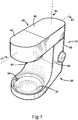
- a stand mixer 10 comprises a generally C-shaped appliance, comprising a base part 20, which includes a pedestal 30 for locating and supporting in an operational position a processing bowl to contain ingredients for processing.
- the stand mixer 10 also includes a head part 40 which is supported and linked to the base part 20 by a generally upright portion 50.
- the stand mixer 10 further contains an electric drive motor (which is not shown, but is usually located either in the generally upright portion 50 or in the head part 40) and transmission means including gearing (not shown) which conveys the motive power supplied by the motor to a drive outlet 42 to which shanked tools can be attached to perform various culinary tasks, such as mixing, kneading etc.
- the drive outlet 42 is configured to impart a planetary drive to one or more shanked tools temporarily attached to the outlet and intended for food mixing and/or kneading.
- the drive outlet 42 is disposed in operation overhead of the pedestal 30, such that the tool or tools driven therefrom depend downwardly from the outlet into the processing bowl (not shown in Figures 1 or 2 ).
- the head part 40 may be configured with further drive outlets providing drive speeds and characteristics suitable for a high-speed blender drive and/or a slow-speed mincer drive for example.
- a shanked mixing tool attached as is conventional, to a socket 44 of the drive outlet 42, will depend in use into a processing bowl placed on the pedestal 30, and is configured to rotate about both the axis of the socket 44 and the central axis 45 of the outlet 42, thus performing a planetary mixing action.
- the necessary relationships between the relative shapes and dimensions of the bowl and the mixing tool to ensure thorough and repeatable mixing of ingredients are well known and established in use over many years.
- the stand mixer 10 is, in this example, provided with a pair of latches 32, 34 extending from a peripheral wall 36 of the pedestal 30, which latches co-operate with components on the base of the bowl to form a bayonet latching system which ensures firm and ready location of the bowl on its platform.
- Other latching systems such as screw-threading for example, can be used as an alternative to bayonet latching if preferred.
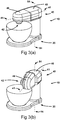
- the generally upright casing portion 50 of the stand mixer 10 is configured with a break line, shown dashed at 52, and a suitable mechanism to permit the head part 40 of the stand mixer to be hinged upwardly, away from the pedestal 30, in order to facilitate the insertion and removal of the mixing tools and the bowl.
- a principal objective of the present invention is to do away with the standard method of raising the head and removing the tool from the mixing bowl.
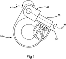
- the head part 40 of the stand mixer 10 though not strictly tubular, is generally elongate and can be regarded as having an axis, shown by the dashed line 41 extending through its centre, and that the axis 41 is disposed generally horizontally when the stand mixer is ready for use.
- the head part is, in this embodiment of the invention, comprised of a first part 46 supporting the drive outlet 42 and a second part 48 which links to it and to the upright portion 50.
- the first and second parts share the common axis 41 and, in accordance with this example of the invention, the first part 46 of the head unit may be rotated, relative to the said second part 48, through (in this example) 90 degrees about the axis 41 to turn the drive outlet 42, and any tools attached thereto, away from the generally vertically disposed operational position, and into a generally horizontal orientation. With the first part 46 of the head so rotated, the tool or tools can be readily withdrawn from the drive outlet 42 for cleaning or replacement with alternative tools.
- the rotation of the drive outlet 42 from its downward-facing (operational) position to the raised position also facilitates the removal of the processing bowl from, or its placement upon, the pedestal 30.
- a linear coupling can be used, if desired, allowing the bowl to be presented axially towards the pedestal 30 from the front and slid thereupon for latching by any convenient means.
- the relative rotation of the parts 46 and 48 can be accommodated by any convenient mechanism or means.
- the transmission mechanism between the electrical drive motor and the drive outlet 42 may be designed to accommodate the necessary degree of relative rotation by free running, without disconnection of any part of the mechanism.
- the part 46 may be first linearly movable along the axis 41 away from part 48, thereby to temporarily separate two components of the transmission, before the rotation is effected.
- the axial movement may be spring-assisted, and may require the actuation of a latching button or catch.
- the head unit 40 can additionally be swung arcuately through an angle of about 30 degrees about a vertical axis 54 through the upright section 50, thereby further facilitating the removal and placement of the bowl on the pedestal 20.
- the aforementioned rotation about the horizontal axis 41 and the arcuate movement about the vertical axis 54 are linked such that the user, having actuated a latch device, simply pushes the head unit 40 to one side or the other of the bowl, so as to manually perform the arcuate movement of about 30 degrees about axis 54, and the internal linkage causes the head unit 40 to simultaneously rotate through 90 degrees about the horizontal axis 41.
- the internal linkage is thus, in this example, configured to have a gearing ratio of 3:1, though it will be appreciated that other ratios can be used, depending on operational parameters and features such as the relative designs of the tools and the processing bowl, which can in part determine how much arcuate movement, if any, is required.
- the movements about axis 41 and/or 54 may optionally be motor-driven, or motor-assisted, and the motor used for such drive or assistance may be a dedicated motor or may comprise the motor used to drive the tools by way of the head 40.
- an interlocking safety cut-out arrangement which disables the motor when the part 46 is rotated into the raised (non-operational) position, thereby to avoid the risk of injury if a user should actuate the motor with tools inserted into the drive outlet 42 and the part 46 rotated away from its operational position.
- a cut-out can be provided in any convenient manner, employing position sensors such as magnets or mobile actuators operating switches.
Landscapes
- Engineering & Computer Science (AREA)
- Chemical & Material Sciences (AREA)
- Chemical Kinetics & Catalysis (AREA)
- Mechanical Engineering (AREA)
- Food Science & Technology (AREA)
- Food-Manufacturing Devices (AREA)
Claims (12)
- Robot pâtissier sur socle (10) comprenant une tête (40) prévue pour supporter un ou plusieurs outils suspendus à celle-ci, un moyen (50) de constituer un support pour supporter ladite tête (40) au-dessus d'un emplacement de réception (30) destiné à un bol à mélanger tel que lesdits un ou plusieurs outils pendent dirigés vers ledit emplacement de bol (30), et un moyen comprenant un moteur électrique et un moyen de transmission associé pour appliquer, à l'aide de la tête (40), un mouvement planétaire auxdits un ou plusieurs outils, le robot pâtissier (10) étant caractérisé en ce que ladite tête (40) comprend une première partie (46) contenant un moyen de constituer une sortie d'entraînement (42) pour lesdits un ou plusieurs outils et une deuxième partie (48) reliant ladite première partie (46) audit moyen de constituer un support (30, 50); les première et deuxième parties (46, 48) ayant un axe commun (41) placé globalement horizontalement pendant l'utilisation, et par le biais duquel la première partie (46) de ladite tête (40) peut subir une rotation, relativement à ladite deuxième partie (48), autour dudit axe (41) pour relever lesdits un ou plusieurs outils en les éloignant dudit emplacement de bol (30).
- Robot pâtissier sur socle selon la revendication 1, comprenant en outre un socle de support de bol (30) définissant ledit emplacement de réception de bol, et dans lequel le moyen de constituer un support comprend une section verticale (50) reliant le socle (30) et la tête (40), de telle manière que la tête (40) se trouve au-dessus du socle (30).
- Robot pâtissier sur socle selon la revendication 2, comprenant en outre un moyen adapté de déplacer la tête (40) dans sa totalité avec précision, autour d'un deuxième axe (54) globalement orthogonal à l'axe mentionné en premier (41), permettant ainsi à un bol de préparation d'être enlevé du socle (30) ou placé dessus plus facilement.
- Robot pâtissier sur socle selon la revendication 3, dans lequel le deuxième axe (54) se prolonge le long de ladite section verticale (50) et un mécanisme pivotant est fourni dans ladite section verticale (50) pour permettre ledit déplacement avec précision.
- Robot pâtissier sur socle selon la revendication 3 ou la revendication 4, comprenant en outre un moyen de relier pour relier ledit déplacement avec précision audit mouvement de rotation, de manière à ce que le mouvement de rotation s'effectue automatiquement quand le déplacement avec précision est effectué par un utilisateur.
- Robot pâtissier sur socle selon l'une quelconque des revendications 2 à 5, dans lequel le moteur électrique est fourni dans ladite section verticale (50).
- Robot pâtissier sur socle selon l'une quelconque des revendications 1 à 6, dans lequel le moteur électrique est fourni dans ladite tête (40).
- Robot pâtissier sur socle selon l'une quelconque des revendications précédentes, dans lequel le moyen de transmission est adapté pour permettre à ladite rotation relative entre les première et deuxième parties (46, 48) de la tête (40) de se produire par le biais de raccords mécaniques à ajustement avec jeu moyen.
- Robot pâtissier sur socle selon l'une quelconque des revendications 1 à 7, dans lequel la première partie (46) de la tête (40) est axialement mobile par rapport à la deuxième partie (48), le mouvement axial étant suffisant pour séparer temporairement un raccord mécanique constituant une partie dudit moyen de transmission, pour permettre ainsi à ladite rotation de se produire sans qu'il soit nécessaire de faire tourner les éléments dans la transmission ou l'entraînement du moteur.
- Robot pâtissier sur socle selon la revendication 9, dans lequel ledit mouvement axial se produit grâce à un ressort.
- Robot pâtissier sur socle selon l'une quelconque des revendications précédentes, comprenant en outre un dispositif de coupure de sécurité adapté pour désactiver le fonctionnement dudit moteur quand la première partie (46) est en rotation relative par rapport à la deuxième partie (48), pour relever lesdits un ou plusieurs outils en les éloignant dudit emplacement de réception de bol (30).
- Robot pâtissier sur socle selon l'une quelconque des revendications précédentes, dans lequel l'emplacement de réception de bol (30) comprend un arrangement de réception de bol capable d'accepter un bol introduit dedans de manière axiale.
Applications Claiming Priority (2)
| Application Number | Priority Date | Filing Date | Title |
|---|---|---|---|
| GB1200044.4A GB2498189B (en) | 2012-01-04 | 2012-01-04 | Stand mixers |
| PCT/GB2012/053136 WO2013102753A1 (fr) | 2012-01-04 | 2012-12-14 | Batteurs sur socle |
Publications (2)
| Publication Number | Publication Date |
|---|---|
| EP2800623A1 EP2800623A1 (fr) | 2014-11-12 |
| EP2800623B1 true EP2800623B1 (fr) | 2017-02-01 |
Family
ID=45755691
Family Applications (1)
| Application Number | Title | Priority Date | Filing Date |
|---|---|---|---|
| EP12812698.4A Not-in-force EP2800623B1 (fr) | 2012-01-04 | 2012-12-14 | Batteurs sur socle |
Country Status (5)
| Country | Link |
|---|---|
| EP (1) | EP2800623B1 (fr) |
| AU (1) | AU2012364304B2 (fr) |
| GB (1) | GB2498189B (fr) |
| IL (1) | IL233440B (fr) |
| WO (1) | WO2013102753A1 (fr) |
Families Citing this family (3)
| Publication number | Priority date | Publication date | Assignee | Title |
|---|---|---|---|---|
| WO2015097200A1 (fr) * | 2013-12-26 | 2015-07-02 | Koninklijke Philips N.V. | Appareil de cuisine ayant un mécanisme d'ouverture |
| CN106618268A (zh) * | 2016-12-16 | 2017-05-10 | 中山市伊丝顿电器有限公司 | 一种可抬头的食品料理机 |
| DE102017000418B4 (de) | 2017-01-11 | 2021-02-11 | Mussa Jani | Küchenmaschine mit Kochfunktion |
Family Cites Families (7)
| Publication number | Priority date | Publication date | Assignee | Title |
|---|---|---|---|---|
| DE2446604A1 (de) * | 1974-09-30 | 1976-04-08 | Siemens Ag | Kuechenmaschine |
| FR2317567A1 (fr) * | 1976-07-20 | 1977-02-04 | Grandvuinet Maurice | Perfectionnements aux moto-reducteurs du type a vis sans fin et a roue creuse |
| DE2930533C2 (de) * | 1979-07-27 | 1983-04-07 | Bosch-Siemens Hausgeräte GmbH, 7000 Stuttgart | Haushaltsgerät, insbesondere Mehrzweck-Küchenmaschine für verschiedene Arbeitsgeräte |
| DE102005040544A1 (de) * | 2005-08-26 | 2007-03-01 | BSH Bosch und Siemens Hausgeräte GmbH | Küchengerät mit einer verstärkten Elektromotor-Getriebestufen-Anordnung und Verfahren zum Herstellen eines elektromotorischen Küchengeräts |
| US20070159917A1 (en) * | 2006-01-09 | 2007-07-12 | Beesley Brian K | Pivoting handheld food preparation appliance and associated method |
| GB2448749B (en) * | 2007-04-27 | 2010-09-22 | Kenwood Ltd | Improvements in or relating to stand mixers |
| GB2459309A (en) * | 2008-04-19 | 2009-10-21 | Kenwood Ltd | A Stand Mixer with guarding device |
-
2012
- 2012-01-04 GB GB1200044.4A patent/GB2498189B/en not_active Expired - Fee Related
- 2012-12-14 AU AU2012364304A patent/AU2012364304B2/en not_active Ceased
- 2012-12-14 WO PCT/GB2012/053136 patent/WO2013102753A1/fr not_active Ceased
- 2012-12-14 EP EP12812698.4A patent/EP2800623B1/fr not_active Not-in-force
-
2014
- 2014-06-29 IL IL233440A patent/IL233440B/en active IP Right Grant
Also Published As
| Publication number | Publication date |
|---|---|
| GB2498189B (en) | 2018-06-06 |
| AU2012364304B2 (en) | 2016-11-10 |
| GB2498189A (en) | 2013-07-10 |
| IL233440A0 (en) | 2014-08-31 |
| AU2012364304A1 (en) | 2014-08-21 |
| IL233440B (en) | 2018-06-28 |
| WO2013102753A1 (fr) | 2013-07-11 |
| GB201200044D0 (en) | 2012-02-15 |
| EP2800623A1 (fr) | 2014-11-12 |
Similar Documents
| Publication | Publication Date | Title |
|---|---|---|
| CN112203565A (zh) | 食品加工设备 | |
| CN102892344B (zh) | 组合榨汁机-搅拌机 | |
| EP3466308B1 (fr) | Mélangeurs de socle | |
| EP2142058B1 (fr) | Batteurs sur socle perfectionnés | |
| EP2800623B1 (fr) | Batteurs sur socle | |
| EP3013198B1 (fr) | Batteurs sur pied | |
| CN102657485B (zh) | 一种折叠式食品搅拌器 | |
| GB2453546A (en) | Planetary drive system | |
| EP2429364B1 (fr) | Dispositif pour traiter et cuire des aliments | |
| KR20210130103A (ko) | 조리 시스템 및 조리 기기 | |
| AU2013357000A1 (en) | Food mixing arrangement | |
| CN212996114U (zh) | 烹饪制备家电系统及用于其的可移除的附件组件和附件架 | |
| EP3030120A1 (fr) | Mixeur électrique | |
| CN102197965A (zh) | 用于烹饪制备的家电设备 | |
| CN202636710U (zh) | 一种折叠式食品搅拌器 | |
| CN105813522B (zh) | 包括被底座承载的下臂和通过铰接装置与所述下臂连接的上臂的烹饪制备家电设备 | |
| CN105828677B (zh) | 包括底座、下臂和枢转地安装在所述下臂上的上臂的烹饪制备家电设备 | |
| EP3060091B1 (fr) | Robot de cuisine à élément anti-éclaboussure | |
| CN105848542B (zh) | 包括被底座承载的下臂和通过铰接装置与所述下臂连接的上臂的烹饪制备家电设备 | |
| CN110477773B (zh) | 一种高效破壁方法 | |
| JP3186675U (ja) | 攪拌装置 | |
| CN105559592A (zh) | 易清洁豆浆机 | |
| JP3186892U (ja) | 攪拌装置 | |
| CN105813521B (zh) | 包括通过铰接装置彼此连接的底座、下臂和上臂的烹饪制备家电设备 | |
| CN116616627A (zh) | 一种厨房用搅拌机 |
Legal Events
| Date | Code | Title | Description |
|---|---|---|---|
| PUAI | Public reference made under article 153(3) epc to a published international application that has entered the european phase |
Free format text: ORIGINAL CODE: 0009012 |
|
| 17P | Request for examination filed |
Effective date: 20140728 |
|
| AK | Designated contracting states |
Kind code of ref document: A1 Designated state(s): AL AT BE BG CH CY CZ DE DK EE ES FI FR GB GR HR HU IE IS IT LI LT LU LV MC MK MT NL NO PL PT RO RS SE SI SK SM TR |
|
| DAX | Request for extension of the european patent (deleted) | ||
| 17Q | First examination report despatched |
Effective date: 20151007 |
|
| GRAP | Despatch of communication of intention to grant a patent |
Free format text: ORIGINAL CODE: EPIDOSNIGR1 |
|
| INTG | Intention to grant announced |
Effective date: 20160726 |
|
| GRAS | Grant fee paid |
Free format text: ORIGINAL CODE: EPIDOSNIGR3 |
|
| GRAA | (expected) grant |
Free format text: ORIGINAL CODE: 0009210 |
|
| AK | Designated contracting states |
Kind code of ref document: B1 Designated state(s): AL AT BE BG CH CY CZ DE DK EE ES FI FR GB GR HR HU IE IS IT LI LT LU LV MC MK MT NL NO PL PT RO RS SE SI SK SM TR |
|
| REG | Reference to a national code |
Ref country code: GB Ref legal event code: FG4D |
|
| REG | Reference to a national code |
Ref country code: CH Ref legal event code: EP Ref country code: AT Ref legal event code: REF Ref document number: 865070 Country of ref document: AT Kind code of ref document: T Effective date: 20170215 |
|
| REG | Reference to a national code |
Ref country code: IE Ref legal event code: FG4D |
|
| REG | Reference to a national code |
Ref country code: DE Ref legal event code: R096 Ref document number: 602012028388 Country of ref document: DE |
|
| REG | Reference to a national code |
Ref country code: NL Ref legal event code: FP |
|
| REG | Reference to a national code |
Ref country code: LT Ref legal event code: MG4D |
|
| REG | Reference to a national code |
Ref country code: AT Ref legal event code: MK05 Ref document number: 865070 Country of ref document: AT Kind code of ref document: T Effective date: 20170201 |
|
| PG25 | Lapsed in a contracting state [announced via postgrant information from national office to epo] |
Ref country code: GR Free format text: LAPSE BECAUSE OF FAILURE TO SUBMIT A TRANSLATION OF THE DESCRIPTION OR TO PAY THE FEE WITHIN THE PRESCRIBED TIME-LIMIT Effective date: 20170502 Ref country code: HR Free format text: LAPSE BECAUSE OF FAILURE TO SUBMIT A TRANSLATION OF THE DESCRIPTION OR TO PAY THE FEE WITHIN THE PRESCRIBED TIME-LIMIT Effective date: 20170201 Ref country code: LT Free format text: LAPSE BECAUSE OF FAILURE TO SUBMIT A TRANSLATION OF THE DESCRIPTION OR TO PAY THE FEE WITHIN THE PRESCRIBED TIME-LIMIT Effective date: 20170201 Ref country code: IS Free format text: LAPSE BECAUSE OF FAILURE TO SUBMIT A TRANSLATION OF THE DESCRIPTION OR TO PAY THE FEE WITHIN THE PRESCRIBED TIME-LIMIT Effective date: 20170601 Ref country code: NO Free format text: LAPSE BECAUSE OF FAILURE TO SUBMIT A TRANSLATION OF THE DESCRIPTION OR TO PAY THE FEE WITHIN THE PRESCRIBED TIME-LIMIT Effective date: 20170501 Ref country code: FI Free format text: LAPSE BECAUSE OF FAILURE TO SUBMIT A TRANSLATION OF THE DESCRIPTION OR TO PAY THE FEE WITHIN THE PRESCRIBED TIME-LIMIT Effective date: 20170201 |
|
| PG25 | Lapsed in a contracting state [announced via postgrant information from national office to epo] |
Ref country code: LV Free format text: LAPSE BECAUSE OF FAILURE TO SUBMIT A TRANSLATION OF THE DESCRIPTION OR TO PAY THE FEE WITHIN THE PRESCRIBED TIME-LIMIT Effective date: 20170201 Ref country code: PL Free format text: LAPSE BECAUSE OF FAILURE TO SUBMIT A TRANSLATION OF THE DESCRIPTION OR TO PAY THE FEE WITHIN THE PRESCRIBED TIME-LIMIT Effective date: 20170201 Ref country code: BG Free format text: LAPSE BECAUSE OF FAILURE TO SUBMIT A TRANSLATION OF THE DESCRIPTION OR TO PAY THE FEE WITHIN THE PRESCRIBED TIME-LIMIT Effective date: 20170501 Ref country code: SE Free format text: LAPSE BECAUSE OF FAILURE TO SUBMIT A TRANSLATION OF THE DESCRIPTION OR TO PAY THE FEE WITHIN THE PRESCRIBED TIME-LIMIT Effective date: 20170201 Ref country code: ES Free format text: LAPSE BECAUSE OF FAILURE TO SUBMIT A TRANSLATION OF THE DESCRIPTION OR TO PAY THE FEE WITHIN THE PRESCRIBED TIME-LIMIT Effective date: 20170201 Ref country code: AT Free format text: LAPSE BECAUSE OF FAILURE TO SUBMIT A TRANSLATION OF THE DESCRIPTION OR TO PAY THE FEE WITHIN THE PRESCRIBED TIME-LIMIT Effective date: 20170201 Ref country code: PT Free format text: LAPSE BECAUSE OF FAILURE TO SUBMIT A TRANSLATION OF THE DESCRIPTION OR TO PAY THE FEE WITHIN THE PRESCRIBED TIME-LIMIT Effective date: 20170601 Ref country code: RS Free format text: LAPSE BECAUSE OF FAILURE TO SUBMIT A TRANSLATION OF THE DESCRIPTION OR TO PAY THE FEE WITHIN THE PRESCRIBED TIME-LIMIT Effective date: 20170201 |
|
| PG25 | Lapsed in a contracting state [announced via postgrant information from national office to epo] |
Ref country code: EE Free format text: LAPSE BECAUSE OF FAILURE TO SUBMIT A TRANSLATION OF THE DESCRIPTION OR TO PAY THE FEE WITHIN THE PRESCRIBED TIME-LIMIT Effective date: 20170201 Ref country code: SK Free format text: LAPSE BECAUSE OF FAILURE TO SUBMIT A TRANSLATION OF THE DESCRIPTION OR TO PAY THE FEE WITHIN THE PRESCRIBED TIME-LIMIT Effective date: 20170201 Ref country code: CZ Free format text: LAPSE BECAUSE OF FAILURE TO SUBMIT A TRANSLATION OF THE DESCRIPTION OR TO PAY THE FEE WITHIN THE PRESCRIBED TIME-LIMIT Effective date: 20170201 Ref country code: RO Free format text: LAPSE BECAUSE OF FAILURE TO SUBMIT A TRANSLATION OF THE DESCRIPTION OR TO PAY THE FEE WITHIN THE PRESCRIBED TIME-LIMIT Effective date: 20170201 |
|
| REG | Reference to a national code |
Ref country code: DE Ref legal event code: R097 Ref document number: 602012028388 Country of ref document: DE |
|
| PG25 | Lapsed in a contracting state [announced via postgrant information from national office to epo] |
Ref country code: DK Free format text: LAPSE BECAUSE OF FAILURE TO SUBMIT A TRANSLATION OF THE DESCRIPTION OR TO PAY THE FEE WITHIN THE PRESCRIBED TIME-LIMIT Effective date: 20170201 Ref country code: SM Free format text: LAPSE BECAUSE OF FAILURE TO SUBMIT A TRANSLATION OF THE DESCRIPTION OR TO PAY THE FEE WITHIN THE PRESCRIBED TIME-LIMIT Effective date: 20170201 |
|
| PLBE | No opposition filed within time limit |
Free format text: ORIGINAL CODE: 0009261 |
|
| STAA | Information on the status of an ep patent application or granted ep patent |
Free format text: STATUS: NO OPPOSITION FILED WITHIN TIME LIMIT |
|
| REG | Reference to a national code |
Ref country code: FR Ref legal event code: PLFP Year of fee payment: 6 |
|
| 26N | No opposition filed |
Effective date: 20171103 |
|
| PG25 | Lapsed in a contracting state [announced via postgrant information from national office to epo] |
Ref country code: SI Free format text: LAPSE BECAUSE OF FAILURE TO SUBMIT A TRANSLATION OF THE DESCRIPTION OR TO PAY THE FEE WITHIN THE PRESCRIBED TIME-LIMIT Effective date: 20170201 |
|
| REG | Reference to a national code |
Ref country code: CH Ref legal event code: PL |
|
| REG | Reference to a national code |
Ref country code: IE Ref legal event code: MM4A |
|
| PG25 | Lapsed in a contracting state [announced via postgrant information from national office to epo] |
Ref country code: MT Free format text: LAPSE BECAUSE OF NON-PAYMENT OF DUE FEES Effective date: 20171214 Ref country code: LU Free format text: LAPSE BECAUSE OF NON-PAYMENT OF DUE FEES Effective date: 20171214 |
|
| REG | Reference to a national code |
Ref country code: BE Ref legal event code: MM Effective date: 20171231 |
|
| PG25 | Lapsed in a contracting state [announced via postgrant information from national office to epo] |
Ref country code: IE Free format text: LAPSE BECAUSE OF NON-PAYMENT OF DUE FEES Effective date: 20171214 |
|
| PG25 | Lapsed in a contracting state [announced via postgrant information from national office to epo] |
Ref country code: LI Free format text: LAPSE BECAUSE OF NON-PAYMENT OF DUE FEES Effective date: 20171231 Ref country code: BE Free format text: LAPSE BECAUSE OF NON-PAYMENT OF DUE FEES Effective date: 20171231 Ref country code: CH Free format text: LAPSE BECAUSE OF NON-PAYMENT OF DUE FEES Effective date: 20171231 |
|
| PG25 | Lapsed in a contracting state [announced via postgrant information from national office to epo] |
Ref country code: HU Free format text: LAPSE BECAUSE OF FAILURE TO SUBMIT A TRANSLATION OF THE DESCRIPTION OR TO PAY THE FEE WITHIN THE PRESCRIBED TIME-LIMIT; INVALID AB INITIO Effective date: 20121214 Ref country code: MC Free format text: LAPSE BECAUSE OF FAILURE TO SUBMIT A TRANSLATION OF THE DESCRIPTION OR TO PAY THE FEE WITHIN THE PRESCRIBED TIME-LIMIT Effective date: 20170201 |
|
| PG25 | Lapsed in a contracting state [announced via postgrant information from national office to epo] |
Ref country code: CY Free format text: LAPSE BECAUSE OF FAILURE TO SUBMIT A TRANSLATION OF THE DESCRIPTION OR TO PAY THE FEE WITHIN THE PRESCRIBED TIME-LIMIT Effective date: 20170201 |
|
| PG25 | Lapsed in a contracting state [announced via postgrant information from national office to epo] |
Ref country code: MK Free format text: LAPSE BECAUSE OF FAILURE TO SUBMIT A TRANSLATION OF THE DESCRIPTION OR TO PAY THE FEE WITHIN THE PRESCRIBED TIME-LIMIT Effective date: 20170201 |
|
| PG25 | Lapsed in a contracting state [announced via postgrant information from national office to epo] |
Ref country code: TR Free format text: LAPSE BECAUSE OF FAILURE TO SUBMIT A TRANSLATION OF THE DESCRIPTION OR TO PAY THE FEE WITHIN THE PRESCRIBED TIME-LIMIT Effective date: 20170201 |
|
| PG25 | Lapsed in a contracting state [announced via postgrant information from national office to epo] |
Ref country code: AL Free format text: LAPSE BECAUSE OF FAILURE TO SUBMIT A TRANSLATION OF THE DESCRIPTION OR TO PAY THE FEE WITHIN THE PRESCRIBED TIME-LIMIT Effective date: 20170201 |
|
| REG | Reference to a national code |
Ref country code: DE Ref legal event code: R079 Ref document number: 602012028388 Country of ref document: DE Free format text: PREVIOUS MAIN CLASS: B01F0007160000 Ipc: B01F0027800000 |
|
| PGFP | Annual fee paid to national office [announced via postgrant information from national office to epo] |
Ref country code: GB Payment date: 20211223 Year of fee payment: 10 Ref country code: FR Payment date: 20211223 Year of fee payment: 10 |
|
| PGFP | Annual fee paid to national office [announced via postgrant information from national office to epo] |
Ref country code: IT Payment date: 20211220 Year of fee payment: 10 |
|
| PGFP | Annual fee paid to national office [announced via postgrant information from national office to epo] |
Ref country code: NL Payment date: 20211221 Year of fee payment: 10 |
|
| PGFP | Annual fee paid to national office [announced via postgrant information from national office to epo] |
Ref country code: DE Payment date: 20211224 Year of fee payment: 10 |
|
| REG | Reference to a national code |
Ref country code: DE Ref legal event code: R119 Ref document number: 602012028388 Country of ref document: DE |
|
| REG | Reference to a national code |
Ref country code: NL Ref legal event code: MM Effective date: 20230101 |
|
| GBPC | Gb: european patent ceased through non-payment of renewal fee |
Effective date: 20221214 |
|
| PG25 | Lapsed in a contracting state [announced via postgrant information from national office to epo] |
Ref country code: NL Free format text: LAPSE BECAUSE OF NON-PAYMENT OF DUE FEES Effective date: 20230101 |
|
| PG25 | Lapsed in a contracting state [announced via postgrant information from national office to epo] |
Ref country code: GB Free format text: LAPSE BECAUSE OF NON-PAYMENT OF DUE FEES Effective date: 20221214 Ref country code: DE Free format text: LAPSE BECAUSE OF NON-PAYMENT OF DUE FEES Effective date: 20230701 |
|
| PG25 | Lapsed in a contracting state [announced via postgrant information from national office to epo] |
Ref country code: FR Free format text: LAPSE BECAUSE OF NON-PAYMENT OF DUE FEES Effective date: 20221231 |
|
| PG25 | Lapsed in a contracting state [announced via postgrant information from national office to epo] |
Ref country code: IT Free format text: LAPSE BECAUSE OF NON-PAYMENT OF DUE FEES Effective date: 20221214 |