EP2800903B1 - Schaufelummantelungsvorrichtung und montageverfahren für eine schaufelummantelungsvorrichtung - Google Patents
Schaufelummantelungsvorrichtung und montageverfahren für eine schaufelummantelungsvorrichtung Download PDFInfo
- Publication number
- EP2800903B1 EP2800903B1 EP12862735.3A EP12862735A EP2800903B1 EP 2800903 B1 EP2800903 B1 EP 2800903B1 EP 12862735 A EP12862735 A EP 12862735A EP 2800903 B1 EP2800903 B1 EP 2800903B1
- Authority
- EP
- European Patent Office
- Prior art keywords
- blade track
- gas turbine
- turbine engine
- blade
- coupling members
- Prior art date
- Legal status (The legal status is an assumption and is not a legal conclusion. Google has not performed a legal analysis and makes no representation as to the accuracy of the status listed.)
- Not-in-force
Links
- 238000000034 method Methods 0.000 title claims description 4
- 230000033001 locomotion Effects 0.000 claims description 19
- 230000003068 static effect Effects 0.000 claims description 17
- 238000011144 upstream manufacturing Methods 0.000 claims description 10
- 239000011153 ceramic matrix composite Substances 0.000 claims description 7
- 238000010276 construction Methods 0.000 claims description 6
- 239000000463 material Substances 0.000 claims description 2
- 230000008878 coupling Effects 0.000 claims 26
- 238000010168 coupling process Methods 0.000 claims 26
- 238000005859 coupling reaction Methods 0.000 claims 26
- 239000012530 fluid Substances 0.000 description 5
- 230000004048 modification Effects 0.000 description 2
- 238000012986 modification Methods 0.000 description 2
- 230000003044 adaptive effect Effects 0.000 description 1
- 230000004075 alteration Effects 0.000 description 1
- 230000000712 assembly Effects 0.000 description 1
- 238000000429 assembly Methods 0.000 description 1
- 229910010293 ceramic material Inorganic materials 0.000 description 1
- 239000011248 coating agent Substances 0.000 description 1
- 238000000576 coating method Methods 0.000 description 1
- 230000008602 contraction Effects 0.000 description 1
- 230000007123 defense Effects 0.000 description 1
- 230000001419 dependent effect Effects 0.000 description 1
- 238000005516 engineering process Methods 0.000 description 1
- 230000007246 mechanism Effects 0.000 description 1
- 239000002184 metal Substances 0.000 description 1
- 238000010248 power generation Methods 0.000 description 1
- 230000001737 promoting effect Effects 0.000 description 1
- 238000005086 pumping Methods 0.000 description 1
- 230000004044 response Effects 0.000 description 1
Images



Classifications
-
- F—MECHANICAL ENGINEERING; LIGHTING; HEATING; WEAPONS; BLASTING
- F01—MACHINES OR ENGINES IN GENERAL; ENGINE PLANTS IN GENERAL; STEAM ENGINES
- F01D—NON-POSITIVE DISPLACEMENT MACHINES OR ENGINES, e.g. STEAM TURBINES
- F01D11/00—Preventing or minimising internal leakage of working-fluid, e.g. between stages
- F01D11/08—Preventing or minimising internal leakage of working-fluid, e.g. between stages for sealing space between rotor blade tips and stator
-
- F—MECHANICAL ENGINEERING; LIGHTING; HEATING; WEAPONS; BLASTING
- F01—MACHINES OR ENGINES IN GENERAL; ENGINE PLANTS IN GENERAL; STEAM ENGINES
- F01D—NON-POSITIVE DISPLACEMENT MACHINES OR ENGINES, e.g. STEAM TURBINES
- F01D11/00—Preventing or minimising internal leakage of working-fluid, e.g. between stages
- F01D11/005—Sealing means between non relatively rotating elements
-
- F—MECHANICAL ENGINEERING; LIGHTING; HEATING; WEAPONS; BLASTING
- F01—MACHINES OR ENGINES IN GENERAL; ENGINE PLANTS IN GENERAL; STEAM ENGINES
- F01D—NON-POSITIVE DISPLACEMENT MACHINES OR ENGINES, e.g. STEAM TURBINES
- F01D25/00—Component parts, details, or accessories, not provided for in, or of interest apart from, other groups
- F01D25/24—Casings; Casing parts, e.g. diaphragms, casing fastenings
-
- F—MECHANICAL ENGINEERING; LIGHTING; HEATING; WEAPONS; BLASTING
- F05—INDEXING SCHEMES RELATING TO ENGINES OR PUMPS IN VARIOUS SUBCLASSES OF CLASSES F01-F04
- F05D—INDEXING SCHEME FOR ASPECTS RELATING TO NON-POSITIVE-DISPLACEMENT MACHINES OR ENGINES, GAS-TURBINES OR JET-PROPULSION PLANTS
- F05D2230/00—Manufacture
- F05D2230/60—Assembly methods
-
- F—MECHANICAL ENGINEERING; LIGHTING; HEATING; WEAPONS; BLASTING
- F05—INDEXING SCHEMES RELATING TO ENGINES OR PUMPS IN VARIOUS SUBCLASSES OF CLASSES F01-F04
- F05D—INDEXING SCHEME FOR ASPECTS RELATING TO NON-POSITIVE-DISPLACEMENT MACHINES OR ENGINES, GAS-TURBINES OR JET-PROPULSION PLANTS
- F05D2240/00—Components
- F05D2240/10—Stators
- F05D2240/11—Shroud seal segments
-
- Y—GENERAL TAGGING OF NEW TECHNOLOGICAL DEVELOPMENTS; GENERAL TAGGING OF CROSS-SECTIONAL TECHNOLOGIES SPANNING OVER SEVERAL SECTIONS OF THE IPC; TECHNICAL SUBJECTS COVERED BY FORMER USPC CROSS-REFERENCE ART COLLECTIONS [XRACs] AND DIGESTS
- Y02—TECHNOLOGIES OR APPLICATIONS FOR MITIGATION OR ADAPTATION AGAINST CLIMATE CHANGE
- Y02T—CLIMATE CHANGE MITIGATION TECHNOLOGIES RELATED TO TRANSPORTATION
- Y02T50/00—Aeronautics or air transport
- Y02T50/60—Efficient propulsion technologies, e.g. for aircraft
-
- Y—GENERAL TAGGING OF NEW TECHNOLOGICAL DEVELOPMENTS; GENERAL TAGGING OF CROSS-SECTIONAL TECHNOLOGIES SPANNING OVER SEVERAL SECTIONS OF THE IPC; TECHNICAL SUBJECTS COVERED BY FORMER USPC CROSS-REFERENCE ART COLLECTIONS [XRACs] AND DIGESTS
- Y10—TECHNICAL SUBJECTS COVERED BY FORMER USPC
- Y10T—TECHNICAL SUBJECTS COVERED BY FORMER US CLASSIFICATION
- Y10T29/00—Metal working
- Y10T29/49—Method of mechanical manufacture
- Y10T29/49316—Impeller making
- Y10T29/4932—Turbomachine making
Definitions
- the present invention generally relates to turbomachinery components, and more particularly, but not exclusively, to gas turbine engine blade tracks.
- US6315519 discloses a turbine inner shroud and a turbine assembly.
- the turbine assembly includes a turbine stator having a longitudinal axis and having an outer shroud block with opposing and longitudinally outward facing first and second sides having open slots.
- Document US5738490 discloses a seal assembly for a turbine blade tip shroud including a one-piece bent metallic sheet inter-segment seal adapted to fit in a groove formed in the end walls of each shroud segment, wherein the shroud segment has a platform and radially extending ribs, and the seal fits tightly in the groove providing an axial and a radial component to the seal.
- One aspect of the present invention is an apparatus according to Claim 1. Another aspect is a method according to Claim 13. Preferred embodiments are provided in the dependent claims.
- the gas turbine engine 50 includes a compressor 52, combustor 54, and turbine 56 which operate together to provide power.
- the gas turbine engine 50 is operable to provide power to an aircraft.
- aircraft includes, but is not limited to, helicopters, airplanes, unmanned space vehicles, fixed wing vehicles, variable wing vehicles, rotary wing vehicles, unmanned combat aerial vehicles, tailless aircraft, hover crafts, and other airborne and/or extraterrestrial (spacecraft) vehicles.
- present inventions are contemplated for utilization in other applications that may not be coupled with an aircraft such as, for example, industrial applications, power generation, pumping sets, naval propulsion, weapon systems, security systems, perimeter defense/security systems, and the like known to one of ordinary skill in the art.
- the gas turbine engine 50 can take a variety of forms in different embodiments. Though depicted as a single spool engine in the illustrated embodiment, in other forms the gas turbine engine 50 can include any number of other spools.
- the gas turbine engine 50 can be configured as an adaptive cycle and/or variable cycle engine and furthermore can take the form of a turbofan, turbojet, turboprop, or turboshaft engine. Other variations and/or combinations are also contemplated herein.
- the gas turbine engine 50 includes turbomachinery components such as the compressor 52 and turbine 56 which each include rotating features such as one or more rows of rotating blades.
- the turbomachinery components can also include relatively stationary features such as a row of stator vanes, which can either be fixed in place or of the variable kind.
- the turbomachinery components can include other features as well.
- the rotating blades of the turbomachinery components can have a blade track (discussed further below) that is located radially outward of the rotating blades and which can be used to form a flow path for working fluid through the turbomachinery components.
- the blade tracks provide a surface over which the working fluid flows as the fluid reacts with the rotating blades.
- the blade track assembly 58 includes a blade track 60 extending between hangers 62 and 63.
- the blade track 60 includes a forward end 64 and aft end 66 and which takes on the form of a generally annular shape that in various embodiments can be either an integral construction or composed of a variety of blade track segments that together form an annular shape.
- the illustration in Fig. 2 depicts a circumferential portion of the blade track 60 which can be taken to represent either a segment of the blade track 60 or a limited view of an annular blade track 60.
- the forward end 64 and aft end 66 generally extend circumferentially to form in whole or in part the annular shape of a completed blade track.
- the forward end 64 and aft end 66 of the blade track 60 are depicted in the illustrated embodiment as being received within respective openings of the forward hanger 62 and aft hanger 63.
- Either or both ends 64 and 66 can project axially from the blade track 60 along the circumferential length of the blade track 60. Not all forms of the blade track 60, however, need include ends 64 and 66 that project axially.
- Either or both the ends 64 and 66 can be continuous along the length of the blade track 60, but in some embodiments the blade track 60 can include any number of ends 64 and/or 66.
- the blade track 60 included a layered construction but not all embodiments need include multiple layers. Not all embodiments, however, need be layered.
- the blade track 60 of the illustrated embodiment includes a backing 68 and an outer surface 70 which can be coupled together in a variety of manners.
- the blade track 60 includes a ceramic material, such as a ceramic matrix composite.
- the outer surface 70 can be a ceramic matrix composite, and in another example the backing 68 is a ceramic matrix composite and the reference numeral 70 indicates a coating applied/affixed/etc to the ceramic matrix composite 68.
- References to the numeral 68 as the backing and to numeral 70 as the ceramic matrix composite will be understood as being made of convenience only and no limitation is hereby intended regarding the precise form of either 68 or 70 unless stated explicitly to the contrary.
- the backing 68 and the outer surface 70 are shown having generally the same shape, the shapes and/or thicknesses of either or both the backing 68 and outer surface 70 can be different than that which is depicted.
- the outer surface 70 is shown as extending along a portion of the backing 68, but in some embodiments the outer surface 70 can extend along the entirety of the backing 68.
- Other variations of the blade track 60 are contemplated herein.
- the forward hanger 62 and aft hanger 63 are depicted in the illustrated embodiment as having different configurations/geometries/attachments/etc, but not all embodiments need be different.
- the forward hanger 62 and aft hanger 63 of the illustrated embodiment include different radial dimensions such that the forward hanger 62 is relatively radially smaller than the aft hanger 63 such as might be expected when the blade track assembly 58 is used within a turbine section of the gas turbine engine 50.
- the forward hanger 62 and aft hanger 63 of the illustrated embodiment also include different mechanisms though which they are secured within the gas turbine engine 50.
- the forward hanger 62 includes an opening 72 through which a relatively static structure (shown best in Fig.
- the term "static" refers to any suitable component that is not configured to move in an appreciable sense such as with the rotating shaft of the gas turbine engine. Motions such as from thermal expansion/contraction or movement such as a component under load can fall within the meaning of the term static.
- the opening 72 is shown having a radially upper side, radially lower side, and a backstop and can be referred to as a u-shape. In some applications the opening 72 can be used to slidingly couple with the relatively static structure of the gas turbine engine 50. Furthermore, the opening 72 can be configured such that it snap-fits to the relatively static structure. Other fastening techniques are contemplated herein.
- the forward hanger 62 can incorporate an anti-movement feature that cooperates with an anti-movement feature of the relatively static structure of the gas turbine engine 50.
- the hanger 62 can include a slot that mates with a pin that extends from and/or is coupled with the relatively static structure of the gas turbine engine 50.
- Other anti-movement features are contemplated herein.
- the aft hanger 63 of the illustrated embodiment includes a protrusion 74 which is used to couple to the gas turbine engine 50 and secure the aft hanger 63 in place.
- the protrusion 74 can be a flange that is received within a corresponding opening or against a corresponding surface of the gas turbine engine 50.
- the protrusion 74 can extend circumferentially and radially as depicted, but other variations are also contemplated. To set forth just one non-limiting example, the protrusion 74 can extend axially.
- the protrusion 74 can be any length and need not be continuous along the length of the aft hanger 63.
- the aft hanger 63 can be secured to a relatively static portion of the gas turbine engine 50 via one or more pins.
- a pin can extend from the relatively static structure of the gas turbine engine 50 and through an opening of the protrusion 74 to discourage relative movement between the two.
- Other forms of anti-movement features are contemplated herein.
- Either or both the forward hanger 62 and aft hanger 63 include anti-movement features that are located at split lines between adjacent segmented blade tracks 60.
- the anti-movement features can be used to discourage relative movement of blade tracks 60.
- the anti-movement features can be used to assist in aligning or maintaining position of the blade tracks 60 relative to each other and/or relative to the hangers 62 and 63.
- either or both of the hangers 62 and 63 can include dimples that line up between the split lines of the blade tracks 60. An edge of the blade track 60 can engage the dimple to, for example, circumferentially locate the blade track 60.
- the anti-movement features can be used to ensure a spacing between neighboring blade tracks 60.
- the anti-movement feature can be a pin. Other variations are also contemplated herein.
- the openings 76 and 78 in the forward hanger 62 and aft hanger 63, respectively, through which the blade track 60 is received can have different shapes/sizes/geometries/etc, but some embodiments need not be different.
- the distance between the radially inner portion and radially outer portion of the opening 76 can be different than the distance between the radially inner portion and radially outer portion of the opening 78.
- the depth of each opening 76 and 78 can likewise be different in some embodiments, but other embodiments need not be different.
- the openings 76 and 78 of the illustrated embodiment are generally u-shaped having a radially inner and outer portion along with a backstop, but other embodiments can include different shapes.
- the openings 76 and 78 are generally structured to slidingly receive the forward end 64 and aft end 66 of the blade track 60.
- clips 80a and 80b are used to couple the blade track 60 to the forward hanger 62 and aft hanger 63, respectively.
- the illustrated embodiment depicts clips 80a and 80b used in both, some embodiments may not include clips 80a and 80b in either or both forward hanger 62 and aft hanger 63.
- the clips 80a and 80b are capable of flexing in response to a stress, for example when the blade track 60 is coupled with the clips.
- the clips can have openings 82a and 82b that are sized smaller than a dimension of the blade track 60 such as its thickness. Such capability to flex can be used to provide a compressive holding force to the blade track 60 when it is inserted through the openings 82a and 82b.
- the clips 80a and 80b of the illustrated embodiment include rounded bodies 84a and 84b extending between ends 86a/86b and 88a/88b.
- the rounded bodies 84a and 84b can be sized to fit within the openings 76 and 78 and in one form are sized to interact in an interference fit.
- the round bodies 84a and 84b can be flexible such that a fit within the openings 76 and 78 create a stress to secure the clips 80a and 80b.
- the ends 86a/86b and 88a/88b of the illustrated embodiment are turned away from the openings 76 and 78, but other forms are also contemplated herein.
- the clips 80a and 80b in the illustrated embodiment extend along an arc corresponding to the openings 76 and 78, and can be an integral annular shape, or segmented, depending on the application. In some embodiments the clips 80a and 80b can correspond to the length of a segmented blade track 60, but some embodiments can have different lengths. If segmented, the clips 80a and 80b can be placed within an opening 76 or 78 of a segmented blade track 60, or can span a split line between two or more adjacent blade tracks 60. Furthermore, in those embodiments having segmented clips 80a and 80b, not all segments need have the same configuration and/or shape. Variations other than those depicted or discussed are contemplated herein. Though the clips 80a and 80b are shown as having similar configurations, other embodiments of the blade track assembly 58 may include clips having different configurations and sizes, among other possible differences.
- the hangers 62 and 63 include anti-movement features that are structured to interact with corresponding anti-rotation features of the blade track 60 to discourage relative movement between the two.
- the hangers 62 and 63 include anti-movement features 90a and 90b in the form of posts that interact with anti-movement features 92 and 94 (shown with respect to a blade track 60 in Fig. 5 ) in the form of cutouts.
- anti-movement features 90a and 90b in the form of posts that interact with anti-movement features 92 and 94 (shown with respect to a blade track 60 in Fig. 5 ) in the form of cutouts.
- Different configurations of anti-movement features on either or both the hangers 62 and 63 and the blade track 60 are contemplated herein. It should be apparent from the illustration of Fig.
- the anti-movement features 90a and 90b can take a form similar to that of the anti-movement features 92 and 94.
- the anti-movement features 90a and 90b are in the form of semi-circular posts that include an extension 96 and a base 98.
- the semi-circular posts can conform in shape to the semi-circular cutout of the blade track 60.
- the anti-movement features 90a and 90b can be integral with then hangers 62 and 63, or can alternatively be welded/brazed/attached to the hangers 62 and 63.
- a segmented blade track 60 is depicted as having the anti-movement features 92 and 94 arranged at its corners, some embodiments can include anti-movement features 92 and 94 located elsewhere.
- the blade track 60 can have any number of anti-rotation features other than the numbers shown in the illustrated embodiment.
- some embodiments can include anti-rotation features at one or more corners and additional anti-rotation feature(s) located at a position intermediate the corners.
- Other embodiments of the hangers 62 and 63 can likewise include any number of anti-rotation features and can be situated in a variety of locations.
- segmented hangers 62 and 63 can be arranged such that neighboring hangers combine to create an anti-rotation feature that can used to discourage relative movement with a blade track 60.
- the semi-circular embodiment of the anti-rotation feature shown in the illustrated embodiment can be shared between neighboring segmented hangers such that each contributes a part of the semi-circular shape.
- Other variations and combinations are contemplated for the anti-rotation features of both blade track 60 and hangers 62 and 63.
- a clip 100 is used to further discourage relative movement and/or secure one or more of the blade track 60 and hangers 62 and 63. Some embodiments of the blade track assembly 58 may not include the clip 100.
- the clip 100 is flexible and can act as a spring to resist relative motions.
- the clip 100 can include multiple flexible portions that resist motion in one or more directions. Such multiple flexible portions can be separately made and working in conjunction together, whether coupled or not, or can be an integral clip having multiple separate portions.
- the clip 100 is located around the anti-movement feature 90a and 90b and is located between multiple surfaces of the hangers 62 and 63 and blade track 60. Specifically, the clip 100 is located in the illustrated embodiment between the base 98 and an edge of the blade track 60 and is also located between the extension 96 and another edge of the blade track 60.
- Fig. 6 depicts a view of one embodiment of the clip 100.
- the clip 100 is shown as semi-circular in shape, other embodiments of the clip 100 can have other shapes.
- the clip includes multiple portions that can be used collectively to discourage movement in multiple directions as will be described below with regard to the illustrated embodiment.
- the multiple portions of the clip can be separate, or can be coupled together in an assembly or as an integral clip.
- the clip 100 includes a portion having a raised body that can act to discourage relative radial movement between the blade track 60 and the hanger 63, another portion located near a corner between the extension 96 and the base 98, and another portion located between the extension 96 and a surface of the blade track 60 that can discourage relative circumferential and/or axial movement.
- the raised portion that discourages relative radial movement can take on different forms in other embodiments.
- the portion located between the extension 96 and the surface of the blade track 60 that discourages relative circumferential and/or axial movement can take on other forms in different embodiments.
- the clip 100 is not limited to an orthogonal corner between surfaces as depicted but can be used in other settings whether or not a turn associated with the surfaces is at ninety degrees.
- one form of the blade track assembly 58 includes a rib 102 that extends between the hangers 62 and 63.
- the rib 102 is coupled or secured to one or both of the hangers 62 and 63.
- the rib 102 is made of sheet metal, but other constructions/materials/etc are also contemplated herein.
- the rib 102 can partially extend between the hangers 62 and 63 in some embodiments.
- the rib 102 includes a backplate 104 and sides 106, 108 that together form a u-shaped rib 102.
- the backplate 104 of the illustrated embodiment includes a depression forming a u-shape, but other embodiments of the backplate 104 can take on a variety of different forms.
- the sides 106 and 108 can be used to engage one or more blade tracks 60 forming a seal to discourage a working fluid from flowing between blade tracks 60.
- the rib 102 can straddle a split line between segmented blade tracks 60 such that each side 106 and 108 engages different blade tracks 60.
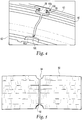
- Fig. 8 shows a view of the rib 102 oriented to straddle a split line between neighboring blade tracks 60, although only one blade track is illustrated for ease of viewing.
- the sides 106 and 108 can have ends that conform to the shape of the blade track 60, although in some embodiments the ends of the sides 106 and 108 need not conform to the blade track 60 at portions or along the entire dimension of the blade track 60.
- Figs. 7 and 8 also illustrate yet further embodiments of the hangers 62 and 63.
- hanger 62 in the illustrated embodiment depicts a scalloped edge 109 in one portion of the hanger 62 that forms the opening 72.
- the scalloped edge can be used to interact with corresponding features in a static structure of the gas turbine engine 50 to place the hanger in position and/or further secure it, among other possible reasons.
- the protrusion 74 of hanger 63 is also arranged as yet another embodiment that includes an axial extension.
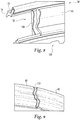
- a blade track 60 can be configured to include a raised portion 110 that engages with the rib 102 (shown in Figs. 7 and 8 ).
- the raised portion 110 can engage one of the sides 106 and 108 substantially along the dimension of the blade track 60 to discourage a working fluid from moving through a split line between adjacent blade tracks 60 and dispersing on the back side of the blade tracks 60.
- the raised portion 110 can be any height difference as measured from a reference point. For example, though an edge of the blade track 60 is shown as raised relative to a middle portion of the blade track segment, some embodiments may include a middle portion that is raised relative to an end portion of the blade.
- the end portion can be, for example, stepped down from the middle portion of the blade track segment 60.
- the raised portion 110 can include a stepped portion that interacts with the rib 102 on its lateral side, or the apex of the raised portion 110 can interact directly with the rib 102. Other variations of a raised seal arrangement are contemplated.
- the blade track assembly 58 can include hangers 62 and 63 without dimples on split lines between blade tracks 60, but include the clip 100 and anti-movement features to secure the one or more hangers to a static structure of the gas turbine engine 50.
- a rib 102 can be used in some blade track assemblies 58 along with a clip 80a, anti-movement feature 90b.
- the upstream side of the blade track assembly 58 can include similar features as those on the downstream side of the blade track assembly 58, but not all embodiments need do so. Numerous other combinations and variations are also contemplated.
Landscapes
- Engineering & Computer Science (AREA)
- Mechanical Engineering (AREA)
- General Engineering & Computer Science (AREA)
- Turbine Rotor Nozzle Sealing (AREA)
- Structures Of Non-Positive Displacement Pumps (AREA)
Claims (13)
- Vorrichtung, die Folgendes umfasst:ein Gasturbinentriebwerk (50), das ein Paar von Gasturbinentriebwerk-Schaufelummantelungskupplungselementen aufweist, die zum Befestigen einer Schaufelummantelung (60) an einem stromaufwärts gelegenen Ende (64) und einem stromabwärts gelegenen Ende (66) verwendbar sind,wobei jedes von dem Paar von Schaufelummantelungskupplungselementen einen sich in Umfangsrichtung erstreckenden Kanal (76; 78) aufweist, der dafür geformt ist, das jeweilige stromaufwärts beziehungsweise stromabwärts gelegene Ende der Schaufelummantelung aufzunehmen,eine flexible Gasturbinentriebwerksklemme (80a; 80b), die sich in einem Bogen erstreckt und dafür strukturiert ist, in einen der sich in Umfangsrichtung erstreckenden Kanäle zu passen,wobei die Triebwerksklemme eine Öffnung (82a; 82b) aufweist, um entweder das stromaufwärts oder das stromabwärts gelegene Ende der Schaufelummantelung aufzunehmen, wobei die Öffnung zwischen einem oberen Ende (86a; 86b) und einem unteren Ende (88a; 88b) eines krummlinigen Klemmenkörpers angeordnet ist, der funktionsfähig ist, um sich zu biegen, wenn die Schaufelummantelung durch die Öffnung eingesetzt wird,wobei wenigstens eines von dem Paar von Schaufelummantelungskupplungselementen ein Kupplungselement-Drehsicherungselement einschließt, das dafür strukturiert ist, eine Bewegung des wenigstens einen von dem Paar von Schaufelummantelungskupplungselementen in Umfangsrichtung im Verhältnis zu einer unbeweglichen Struktur eines Gasturbinentriebwerks (50) zu verhindern, undwobei die Gasturbinentriebwerk-Schaufelummantelung eine Vielzahl von Schaufelummantelungen einschließt, dadurch gekennzeichnet, dass wenigstens eines von dem Paar von Schaufelummantelungskupplungselementen ein Schaufelummantelung-Drehsicherungselement (90a; 90b) einschließt, das dafür strukturiert ist, eine Bewegung der Schaufelummantelung (60) in Umfangsrichtung zu verhindern,wobei wenigstens einige von der Vielzahl von Schaufelummantelungen einen Ausschnitt (92; 94) einschließen, der dafür strukturiert ist, das Schaufelummantelung-Drehsicherungselement in Eingriff zu nehmen, wobei sie ferner Folgendes einschließteine Federklemme (100), die zwischen dem Schaufelummantelung-Drehsicherungselement und wenigstens einer der Vielzahl von Schaufelummantelungen angeordnet ist.
- Vorrichtung nach Anspruch 1, wobei
das Gasturbinentriebwerk (50) eine Turbinensektion (56) aufweist, in der die Gasturbinentriebwerk-Schaufelummantelungskupplungselemente angeordnet sind,
wobei das Paar von Schaufelummantelungskupplungselementen nicht identisch ist und
wobei wenigstens eines von dem Paar von Schaufelummantelungskupplungselementen mit einem Drehsicherungselement in Wechselwirkung steht, um eine Bewegung der Gasturbinentriebwerk-Schaufelummantelungskupplungselemente zu verhindern. - Vorrichtung nach Anspruch 1, wobei ein erstes von dem Paar von Gasturbinentriebwerk-Schaufelummantelungskupplungselementen einen weiteren sich in Umfangsrichtung erstreckenden Kanal (72) einschließt, wobei der weitere sich in Umfangsrichtung erstreckende Kanal von dem sich in Umfangsrichtung erstreckenden Kanal (76) versetzt und dafür konfiguriert ist, eine Struktur eines Gasturbinentriebwerks (50) aufzunehmen, die dafür konfiguriert ist, das erste von dem Paar von Schaufelummantelungskupplungselementen innerhalb des Triebwerks zu positionieren, oder
wobei ein erstes von dem Paar von Gasturbinentriebwerk-Schaufelummantelungskupplungselementen eine Erweiterung (72) einschließt, die dafür strukturiert ist, gleitend mit einer unbeweglichen Struktur eines Gasturbinentriebwerks in Eingriff gebracht zu werden. - Vorrichtung nach Anspruch 1,
wobei eines oder beide von dem Paar von Schaufelummantelungskupplungselementen ein Ausrichtungsmerkmal zum Positionieren einer Schaufelummantelung (60) in Umfangsrichtung einschließen,
wobei das Ausrichtungsmerkmal eine Vertiefung ist, die sich zwischen Trennfugen der Schaufelummantelungen einreiht. - Vorrichtung nach Anspruch 1,
wobei das Paar von Gasturbinentriebwerk-Schaufelummantelungskupplungselementen ein Element einschließt, dass sich in Axialrichtung erstreckt, um das Paar miteinander zu verbinden, und
wobei das Element ein Rippenelement (102) ist, das die Trennfuge (112) zwischen Schaufelummantelungen derart überbrückt, dass Seiten des Rippenelements (106; 108) jeweilige unterschiedliche Schaufelummantelungen in Eingriff nehmen. - Vorrichtung nach Anspruch 1,
wobei jeder der sich in Umfangsrichtung erstreckenden Kanäle (76; 78) ein in Radialrichtung inneres Element und ein in Radialrichtung äußeres Element zum Aufnehmen des stromaufwärts gelegenen Endes (64) und des stromabwärts gelegenen Endes (66) in die jeweiligen Kanäle einschließt und
wobei die Schaufelummantelungskupplungselemente eine Vielzahl von Aufhängern (62; 63) einschließen, welche die sich in Umfangsrichtung erstreckenden Kanäle aufweisen, und
wobei die Schaufelummantelung (60) eine Vielzahl von segmentierten Schaufelummantelungen einschließt und,
wobei die Schaufelummantelungskupplungselemente eine Vielzahl von segmentierten Aufhängern einschließen, die jeweils die sich in Umfangsrichtung erstreckenden Kanäle aufweisen. - Vorrichtung nach Anspruch 1, wobei sich wenigstens eines von dem stromaufwärts und dem stromabwärts gelegenen Ende (64; 66) in Umfangsrichtung über eine beträchtliche Länge der Schaufelummantelung (60) erstreckt oder
wobei die flexible Gasturbinentriebwerksklemme (80a; 80b) eine U-förmige Klemme einschließt, die dafür strukturiert ist, die Schaufelummantelung zu greifen, und dafür geformt, in die sich in Umfangsrichtung erstreckenden Kanäle (76; 78) der Schaufelummantelungskupplungselemente zu passen. - Vorrichtung nach Anspruch 1, wobei die Schaufelummantelungskupplungselemente eine Zwischenstruktur einschließen, die den sich in Umfangsrichtung erstreckenden Kanal (76; 78) zum Aufnehmen eines von dem stromaufwärts und dem stromabwärts gelegenen Ende (64; 68) aufweist, und
einen zweiten Aufnahmeabschnitt (72) zum Aufnehmen eines Vorsprungs einer unbeweglichen Struktur des Gasturbinentriebwerks (50),
wobei
der sich in Umfangsrichtung erstreckende Kanal (76) ein in Radialrichtung inneres und ein in Radialrichtung äußeres Element zum Aufnehmen der Schaufelummantelung (60) in den Kanal einschließt und
der zweite Aufnahmeabschnitt ein zweites in Radialrichtung inneres und ein zweites in Radialrichtung äußeres Element einschließt, die einen zweiten Kanal zum Aufnehmen des Vorsprungs der unbeweglichen Struktur erzeugen. - Vorrichtung nach Anspruch 1, wobei das obere Ende in einem oberen aufgeweiteten Abschnitt der Klemme (80a; 80b) angeordnet ist, der dafür konfiguriert ist, sich von der Öffnung wegzudrehen, und
wobei der obere aufgeweitete Abschnitt die Schaufelummantelung (60) in Eingriff nimmt, wenn er eingebaut wird, und die flexible Beschaffenheit der Klemme eine Kompressionshaltekraft mit der Schaufelummantelung erzeugt. - Vorrichtung nach Anspruch 1, die ferner ein Gasturbinentriebwerk (50) einschließt, das eine Vielzahl der flexiblen Gasturbinentriebwerksklemmen (80a; 80b) umfasst, die in dem sich in Umfangsrichtung erstreckenden Schlitz (76; 78) um einen Ringspalt einer Turbinensektion (56) eines Gasturbinentriebwerks angeordnet sind, und
die ferner eine Vielzahl von segmentierten Schaufelummantelungen (60) einschließt, die einen Kupplungsabschnitt aufweisen, der mit der Vielzahl der flexiblen Gasturbinentriebwerksklemmen in Eingriff ist, und
wobei ein oberer aufgeweiteter Abschnitt der Gasturbinentriebwerksklemme zusammendrückend eine Oberfläche des sich in Umfangsrichtung erstreckenden Schlitzes einer unbeweglichen Gasturbinentriebwerksstruktur in Eingriff nimmt. - Vorrichtung nach Anspruch 1, wobei die Schaufelummantelung (60) einen Keramikmatrix-Verbundwerkstoff einschließt.
- Vorrichtung nach Anspruch 1, wobei die Schaufelummantelung (60) einen geschichteten Aufbau einschließt, der einen äußeren Aufbau (70) und eine Verstärkung (68) einschließt, wobei wenigstens eines von dem äußeren Aufbau und der Verstärkung aus einem Keramikmatrix-Verbundwerkstoff besteht.
- Verfahren zum Zusammenbauen einer Vorrichtung, das Folgendes umfasst:Befestigen einer Schaufelummantelung an einem stromaufwärts gelegenen Ende und einen stromabwärts gelegenen Ende in einem Paar von Gasturbinentriebwerk-Schaufelummantelungskupplungselementen eines Gasturbinentriebwerks,wobei jedes von dem Paar von Schaufelummantelungskupplungselementen einen sich in Umfangsrichtung erstreckenden Kanal aufweist, der dafür geformt ist, das jeweilige stromaufwärts beziehungsweise stromabwärts gelegene Ende der Schaufelummantelung aufzunehmen,Einsetzen einer flexiblen Gasturbinentreibwerksklemme, die sich in einem Bogen erstreckt, in einen der sich in Umfangsrichtung erstreckenden Kanäle,Einsetzen eines von dem stromaufwärts gelegenen Ende und dem stromabwärts gelegenen Ende der Schaufelummantelung durch eine Öffnung in der Triebwerksklemme,wobei die Öffnung zwischen einem oberen Ende und einem unteren Ende eines krummlinigen Klemmenkörpers angeordnet ist, der funktionsfähig ist, um sich zu biegen, wenn die Schaufelummantelung durch die Öffnung eingesetzt wird,wobei wenigstens eines von dem Paar von Schaufelummantelungskupplungselementen ein Schaufelummantelung-Drehsicherungselement einschließt, das dafür strukturiert ist, eine Bewegung der Schaufelummantelung in Umfangsrichtung zu verhindern, und wobei wenigstens eines von dem Paar von Schaufelummantelungskupplungselementen ein Kupplungselement-Drehsicherungselement einschließt, das dafür strukturiert ist, eine Bewegung des wenigstens einen von dem Paar von Schaufelummantelungskupplungselementen in Umfangsrichtung im Verhältnis zu einer unbeweglichen Struktur eines Gasturbinentriebwerks (50) zu verhindern, undwobei die Gasturbinentriebwerk-Schaufelummantelung eine Vielzahl von Schaufelummantelungen einschließt,wobei wenigstens einige von der Vielzahl von Schaufelummantelungen einen Ausschnitt einschließen, der dafür strukturiert ist, das Schaufelummantelung-Drehsicherungselement in Eingriff zu nehmen, wobei sie ferner Folgendes einschließteine Federklemme, die zwischen dem Schaufelummantelung-Drehsicherungselement und wenigstens einer der Vielzahl von Schaufelummantelungen angeordnet ist.
Priority Applications (1)
| Application Number | Priority Date | Filing Date | Title |
|---|---|---|---|
| EP15178939.3A EP2977618B1 (de) | 2011-12-31 | 2012-12-30 | Gasturbinenmotor mit einer mantelringanordnung und zugehöriges montageverfahren |
Applications Claiming Priority (2)
| Application Number | Priority Date | Filing Date | Title |
|---|---|---|---|
| US201161582275P | 2011-12-31 | 2011-12-31 | |
| PCT/US2012/072236 WO2013102171A2 (en) | 2011-12-31 | 2012-12-30 | Blade track assembly, components, and methods |
Related Child Applications (2)
| Application Number | Title | Priority Date | Filing Date |
|---|---|---|---|
| EP15178939.3A Division-Into EP2977618B1 (de) | 2011-12-31 | 2012-12-30 | Gasturbinenmotor mit einer mantelringanordnung und zugehöriges montageverfahren |
| EP15178939.3A Division EP2977618B1 (de) | 2011-12-31 | 2012-12-30 | Gasturbinenmotor mit einer mantelringanordnung und zugehöriges montageverfahren |
Publications (3)
| Publication Number | Publication Date |
|---|---|
| EP2800903A2 EP2800903A2 (de) | 2014-11-12 |
| EP2800903A4 EP2800903A4 (de) | 2015-08-19 |
| EP2800903B1 true EP2800903B1 (de) | 2018-12-05 |
Family
ID=48698818
Family Applications (2)
| Application Number | Title | Priority Date | Filing Date |
|---|---|---|---|
| EP12862735.3A Not-in-force EP2800903B1 (de) | 2011-12-31 | 2012-12-30 | Schaufelummantelungsvorrichtung und montageverfahren für eine schaufelummantelungsvorrichtung |
| EP15178939.3A Not-in-force EP2977618B1 (de) | 2011-12-31 | 2012-12-30 | Gasturbinenmotor mit einer mantelringanordnung und zugehöriges montageverfahren |
Family Applications After (1)
| Application Number | Title | Priority Date | Filing Date |
|---|---|---|---|
| EP15178939.3A Not-in-force EP2977618B1 (de) | 2011-12-31 | 2012-12-30 | Gasturbinenmotor mit einer mantelringanordnung und zugehöriges montageverfahren |
Country Status (3)
| Country | Link |
|---|---|
| US (2) | US9784115B2 (de) |
| EP (2) | EP2800903B1 (de) |
| WO (1) | WO2013102171A2 (de) |
Families Citing this family (15)
| Publication number | Priority date | Publication date | Assignee | Title |
|---|---|---|---|---|
| US9726043B2 (en) | 2011-12-15 | 2017-08-08 | General Electric Company | Mounting apparatus for low-ductility turbine shroud |
| EP2800903B1 (de) * | 2011-12-31 | 2018-12-05 | Rolls-Royce Corporation | Schaufelummantelungsvorrichtung und montageverfahren für eine schaufelummantelungsvorrichtung |
| WO2014158276A2 (en) * | 2013-03-05 | 2014-10-02 | Rolls-Royce Corporation | Structure and method for providing compliance and sealing between ceramic and metallic structures |
| US10378387B2 (en) | 2013-05-17 | 2019-08-13 | General Electric Company | CMC shroud support system of a gas turbine |
| GB2523069A (en) * | 2013-11-27 | 2015-08-19 | Rolls Royce Plc | Gas turbine engine |
| CN105814282B (zh) | 2013-12-12 | 2018-06-05 | 通用电气公司 | Cmc护罩支撑系统 |
| WO2015191169A1 (en) | 2014-06-12 | 2015-12-17 | General Electric Company | Shroud hanger assembly |
| EP3155230B1 (de) | 2014-06-12 | 2022-06-01 | General Electric Company | Mehrteilige ummantelungsaufhängungsanordnung |
| CN106460542B (zh) | 2014-06-12 | 2018-11-02 | 通用电气公司 | 护罩挂架组件 |
| US9874104B2 (en) | 2015-02-27 | 2018-01-23 | General Electric Company | Method and system for a ceramic matrix composite shroud hanger assembly |
| MX2017015859A (es) | 2015-06-30 | 2018-06-27 | Hillman Group Inc | Ensambles de anclaje en pared. |
| CA3148328A1 (en) | 2015-06-30 | 2017-01-05 | The Hillman Group, Inc. | Wall anchor assemblies and related wall mount systems |
| CN108135374B (zh) | 2015-10-23 | 2020-08-04 | 希尔曼集团股份有限公司 | 墙壁锚定件和相关的墙壁安装系统 |
| FR3045716B1 (fr) * | 2015-12-18 | 2018-01-26 | Safran Aircraft Engines | Ensemble d'anneau de turbine avec maintien elastique a froid |
| US10390618B2 (en) | 2016-02-15 | 2019-08-27 | The Hillman Group, Inc. | Wall mountable object support system and related accessories |
Citations (2)
| Publication number | Priority date | Publication date | Assignee | Title |
|---|---|---|---|---|
| US4247248A (en) * | 1978-12-20 | 1981-01-27 | United Technologies Corporation | Outer air seal support structure for gas turbine engine |
| US5738490A (en) * | 1996-05-20 | 1998-04-14 | Pratt & Whitney Canada, Inc. | Gas turbine engine shroud seals |
Family Cites Families (30)
| Publication number | Priority date | Publication date | Assignee | Title |
|---|---|---|---|---|
| US4551064A (en) * | 1982-03-05 | 1985-11-05 | Rolls-Royce Limited | Turbine shroud and turbine shroud assembly |
| US6146091A (en) * | 1998-03-03 | 2000-11-14 | Mitsubishi Heavy Industries, Ltd. | Gas turbine cooling structure |
| FR2780443B1 (fr) * | 1998-06-25 | 2000-08-04 | Snecma | Anneau de stator de turbine haute pression d'une turbomachine |
| US6315519B1 (en) | 1998-09-28 | 2001-11-13 | General Electric Company | Turbine inner shroud and turbine assembly containing such inner shroud |
| FR2800797B1 (fr) * | 1999-11-10 | 2001-12-07 | Snecma | Assemblage d'un anneau bordant une turbine a la structure de turbine |
| WO2001066914A1 (en) * | 2000-03-07 | 2001-09-13 | Mitsubishi Heavy Industries, Ltd. | Gas turbine split ring |
| JP4698847B2 (ja) * | 2001-01-19 | 2011-06-08 | 三菱重工業株式会社 | ガスタービン分割環 |
| US6702550B2 (en) | 2002-01-16 | 2004-03-09 | General Electric Company | Turbine shroud segment and shroud assembly |
| US6733235B2 (en) | 2002-03-28 | 2004-05-11 | General Electric Company | Shroud segment and assembly for a turbine engine |
| US6877952B2 (en) * | 2002-09-09 | 2005-04-12 | Florida Turbine Technologies, Inc | Passive clearance control |
| JP4269829B2 (ja) * | 2003-07-04 | 2009-05-27 | 株式会社Ihi | シュラウドセグメント |
| US7052235B2 (en) | 2004-06-08 | 2006-05-30 | General Electric Company | Turbine engine shroud segment, hanger and assembly |
| US7207771B2 (en) * | 2004-10-15 | 2007-04-24 | Pratt & Whitney Canada Corp. | Turbine shroud segment seal |
| US7575409B2 (en) * | 2005-07-01 | 2009-08-18 | Allison Advanced Development Company | Apparatus and method for active control of blade tip clearance |
| US7278820B2 (en) | 2005-10-04 | 2007-10-09 | Siemens Power Generation, Inc. | Ring seal system with reduced cooling requirements |
| US7556475B2 (en) | 2006-05-31 | 2009-07-07 | General Electric Company | Methods and apparatus for assembling turbine engines |
| US7722317B2 (en) | 2007-01-25 | 2010-05-25 | Siemens Energy, Inc. | CMC to metal attachment mechanism |
| FR2913718B1 (fr) | 2007-03-15 | 2009-06-05 | Snecma Propulsion Solide Sa | Ensemble d'anneau de turbine pour turbine a gaz |
| US8061977B2 (en) | 2007-07-03 | 2011-11-22 | Siemens Energy, Inc. | Ceramic matrix composite attachment apparatus and method |
| US8047773B2 (en) | 2007-08-23 | 2011-11-01 | General Electric Company | Gas turbine shroud support apparatus |
| US7887929B2 (en) | 2007-08-28 | 2011-02-15 | United Technologies Corporation | Oriented fiber ceramic matrix composite abradable thermal barrier coating |
| US8128350B2 (en) * | 2007-09-21 | 2012-03-06 | Siemens Energy, Inc. | Stacked lamellae ceramic gas turbine ring segment component |
| US8128343B2 (en) * | 2007-09-21 | 2012-03-06 | Siemens Energy, Inc. | Ring segment coolant seal configuration |
| US8177492B2 (en) * | 2008-03-04 | 2012-05-15 | United Technologies Corporation | Passage obstruction for improved inlet coolant filling |
| US8256228B2 (en) * | 2008-04-29 | 2012-09-04 | Rolls Royce Corporation | Turbine blade tip clearance apparatus and method |
| GB0813820D0 (en) * | 2008-07-29 | 2008-09-03 | Rolls Royce Plc | A fan casing for a gas turbine engine |
| GB2477825B (en) * | 2010-09-23 | 2015-04-01 | Rolls Royce Plc | Anti fret liner assembly |
| US8596969B2 (en) * | 2010-12-22 | 2013-12-03 | United Technologies Corporation | Axial retention feature for gas turbine engine vanes |
| US8985944B2 (en) * | 2011-03-30 | 2015-03-24 | General Electric Company | Continuous ring composite turbine shroud |
| EP2800903B1 (de) * | 2011-12-31 | 2018-12-05 | Rolls-Royce Corporation | Schaufelummantelungsvorrichtung und montageverfahren für eine schaufelummantelungsvorrichtung |
-
2012
- 2012-12-30 EP EP12862735.3A patent/EP2800903B1/de not_active Not-in-force
- 2012-12-30 EP EP15178939.3A patent/EP2977618B1/de not_active Not-in-force
- 2012-12-30 WO PCT/US2012/072236 patent/WO2013102171A2/en not_active Ceased
-
2014
- 2014-08-13 US US14/458,532 patent/US9784115B2/en active Active
-
2017
- 2017-09-05 US US15/695,476 patent/US10837302B2/en active Active
Patent Citations (2)
| Publication number | Priority date | Publication date | Assignee | Title |
|---|---|---|---|---|
| US4247248A (en) * | 1978-12-20 | 1981-01-27 | United Technologies Corporation | Outer air seal support structure for gas turbine engine |
| US5738490A (en) * | 1996-05-20 | 1998-04-14 | Pratt & Whitney Canada, Inc. | Gas turbine engine shroud seals |
Also Published As
| Publication number | Publication date |
|---|---|
| EP2800903A2 (de) | 2014-11-12 |
| EP2977618A3 (de) | 2016-04-13 |
| WO2013102171A3 (en) | 2013-10-03 |
| US20150016970A1 (en) | 2015-01-15 |
| EP2800903A4 (de) | 2015-08-19 |
| EP2977618B1 (de) | 2019-10-30 |
| WO2013102171A2 (en) | 2013-07-04 |
| US20180010474A1 (en) | 2018-01-11 |
| EP2977618A2 (de) | 2016-01-27 |
| US10837302B2 (en) | 2020-11-17 |
| US9784115B2 (en) | 2017-10-10 |
Similar Documents
| Publication | Publication Date | Title |
|---|---|---|
| EP2800903B1 (de) | Schaufelummantelungsvorrichtung und montageverfahren für eine schaufelummantelungsvorrichtung | |
| US10281045B2 (en) | Apparatus and methods for sealing components in gas turbine engines | |
| US8998573B2 (en) | Resilient mounting apparatus for low-ductility turbine shroud | |
| US8740552B2 (en) | Low-ductility turbine shroud and mounting apparatus | |
| US8684674B2 (en) | Anti-rotation shroud for turbine engines | |
| EP3097273B1 (de) | Halteklammer für eine aussendichtung einer turbinenschaufel | |
| US8579580B2 (en) | Mounting apparatus for low-ductility turbine shroud | |
| EP3030754B1 (de) | Boas mit radiallastfunktion | |
| US10590798B2 (en) | Non-integral blade and platform segment for rotor | |
| EP2964896B1 (de) | System und verfahren zur leckagevermeidung in einer turbine | |
| WO2016163040A1 (ja) | シールド部材及びそれを用いたジェットエンジン | |
| WO2014138078A1 (en) | Flexible finger seal for sealing a gap between turbine engine components | |
| EP3051062B1 (de) | Gasturbinen-ausrichtungszugstangenvorrichtung und verfahren zur verwendung | |
| US10858946B2 (en) | Bladed rotor | |
| EP3097270B1 (de) | Innengehäuse eines gasturbinenmotors mit nicht-integrierten schaufeln | |
| CA2870762A1 (en) | Retaining clip, turbine frame, and method of limiting radial movement |
Legal Events
| Date | Code | Title | Description |
|---|---|---|---|
| PUAI | Public reference made under article 153(3) epc to a published international application that has entered the european phase |
Free format text: ORIGINAL CODE: 0009012 |
|
| 17P | Request for examination filed |
Effective date: 20140731 |
|
| AK | Designated contracting states |
Kind code of ref document: A2 Designated state(s): AL AT BE BG CH CY CZ DE DK EE ES FI FR GB GR HR HU IE IS IT LI LT LU LV MC MK MT NL NO PL PT RO RS SE SI SK SM TR |
|
| DAX | Request for extension of the european patent (deleted) | ||
| RIN1 | Information on inventor provided before grant (corrected) |
Inventor name: GRIFFITHS, GEORGE, F. Inventor name: FREEMAN, TED, JOSEPH Inventor name: SMITH, CLAYTON, C. Inventor name: WESTPHAL, WILLIAM |
|
| A4 | Supplementary search report drawn up and despatched |
Effective date: 20150721 |
|
| RIC1 | Information provided on ipc code assigned before grant |
Ipc: F01D 25/24 20060101ALI20150715BHEP Ipc: F04D 27/02 20060101AFI20150715BHEP Ipc: F01D 11/08 20060101ALI20150715BHEP Ipc: F01D 21/04 20060101ALI20150715BHEP Ipc: F01D 5/14 20060101ALI20150715BHEP Ipc: F01D 11/12 20060101ALN20150715BHEP Ipc: F01D 25/08 20060101ALI20150715BHEP |
|
| RAP1 | Party data changed (applicant data changed or rights of an application transferred) |
Owner name: ROLLS-ROYCE NORTH AMERICAN TECHNOLOGIES, INC. Owner name: ROLLS-ROYCE CORPORATION |
|
| STAA | Information on the status of an ep patent application or granted ep patent |
Free format text: STATUS: EXAMINATION IS IN PROGRESS |
|
| 17Q | First examination report despatched |
Effective date: 20170914 |
|
| RIC1 | Information provided on ipc code assigned before grant |
Ipc: F01D 21/04 20060101ALI20180606BHEP Ipc: F04D 27/02 20060101AFI20180606BHEP Ipc: F01D 25/08 20060101ALI20180606BHEP Ipc: F01D 5/14 20060101ALI20180606BHEP Ipc: F01D 11/08 20060101ALI20180606BHEP Ipc: F01D 25/24 20060101ALI20180606BHEP Ipc: F01D 11/12 20060101ALN20180606BHEP |
|
| RIC1 | Information provided on ipc code assigned before grant |
Ipc: F01D 11/12 20060101ALN20180612BHEP Ipc: F01D 25/24 20060101ALI20180612BHEP Ipc: F01D 11/08 20060101ALI20180612BHEP Ipc: F01D 25/08 20060101ALI20180612BHEP Ipc: F01D 5/14 20060101ALI20180612BHEP Ipc: F01D 21/04 20060101ALI20180612BHEP Ipc: F04D 27/02 20060101AFI20180612BHEP |
|
| GRAP | Despatch of communication of intention to grant a patent |
Free format text: ORIGINAL CODE: EPIDOSNIGR1 |
|
| STAA | Information on the status of an ep patent application or granted ep patent |
Free format text: STATUS: GRANT OF PATENT IS INTENDED |
|
| INTG | Intention to grant announced |
Effective date: 20180801 |
|
| GRAS | Grant fee paid |
Free format text: ORIGINAL CODE: EPIDOSNIGR3 |
|
| GRAA | (expected) grant |
Free format text: ORIGINAL CODE: 0009210 |
|
| GRAA | (expected) grant |
Free format text: ORIGINAL CODE: 0009210 |
|
| STAA | Information on the status of an ep patent application or granted ep patent |
Free format text: STATUS: THE PATENT HAS BEEN GRANTED |
|
| AK | Designated contracting states |
Kind code of ref document: B1 Designated state(s): AL AT BE BG CH CY CZ DE DK EE ES FI FR GB GR HR HU IE IS IT LI LT LU LV MC MK MT NL NO PL PT RO RS SE SI SK SM TR |
|
| RAP1 | Party data changed (applicant data changed or rights of an application transferred) |
Owner name: ROLLS-ROYCE NORTH AMERICAN TECHNOLOGIES, INC. Owner name: ROLLS-ROYCE CORPORATION |
|
| REG | Reference to a national code |
Ref country code: GB Ref legal event code: FG4D |
|
| REG | Reference to a national code |
Ref country code: CH Ref legal event code: EP |
|
| REG | Reference to a national code |
Ref country code: AT Ref legal event code: REF Ref document number: 1073433 Country of ref document: AT Kind code of ref document: T Effective date: 20181215 |
|
| REG | Reference to a national code |
Ref country code: IE Ref legal event code: FG4D |
|
| REG | Reference to a national code |
Ref country code: DE Ref legal event code: R096 Ref document number: 602012054499 Country of ref document: DE |
|
| REG | Reference to a national code |
Ref country code: NL Ref legal event code: MP Effective date: 20181205 |
|
| REG | Reference to a national code |
Ref country code: AT Ref legal event code: MK05 Ref document number: 1073433 Country of ref document: AT Kind code of ref document: T Effective date: 20181205 |
|
| REG | Reference to a national code |
Ref country code: LT Ref legal event code: MG4D |
|
| PG25 | Lapsed in a contracting state [announced via postgrant information from national office to epo] |
Ref country code: NO Free format text: LAPSE BECAUSE OF FAILURE TO SUBMIT A TRANSLATION OF THE DESCRIPTION OR TO PAY THE FEE WITHIN THE PRESCRIBED TIME-LIMIT Effective date: 20190305 Ref country code: LT Free format text: LAPSE BECAUSE OF FAILURE TO SUBMIT A TRANSLATION OF THE DESCRIPTION OR TO PAY THE FEE WITHIN THE PRESCRIBED TIME-LIMIT Effective date: 20181205 Ref country code: BG Free format text: LAPSE BECAUSE OF FAILURE TO SUBMIT A TRANSLATION OF THE DESCRIPTION OR TO PAY THE FEE WITHIN THE PRESCRIBED TIME-LIMIT Effective date: 20190305 Ref country code: AT Free format text: LAPSE BECAUSE OF FAILURE TO SUBMIT A TRANSLATION OF THE DESCRIPTION OR TO PAY THE FEE WITHIN THE PRESCRIBED TIME-LIMIT Effective date: 20181205 Ref country code: HR Free format text: LAPSE BECAUSE OF FAILURE TO SUBMIT A TRANSLATION OF THE DESCRIPTION OR TO PAY THE FEE WITHIN THE PRESCRIBED TIME-LIMIT Effective date: 20181205 Ref country code: ES Free format text: LAPSE BECAUSE OF FAILURE TO SUBMIT A TRANSLATION OF THE DESCRIPTION OR TO PAY THE FEE WITHIN THE PRESCRIBED TIME-LIMIT Effective date: 20181205 Ref country code: LV Free format text: LAPSE BECAUSE OF FAILURE TO SUBMIT A TRANSLATION OF THE DESCRIPTION OR TO PAY THE FEE WITHIN THE PRESCRIBED TIME-LIMIT Effective date: 20181205 Ref country code: FI Free format text: LAPSE BECAUSE OF FAILURE TO SUBMIT A TRANSLATION OF THE DESCRIPTION OR TO PAY THE FEE WITHIN THE PRESCRIBED TIME-LIMIT Effective date: 20181205 |
|
| PG25 | Lapsed in a contracting state [announced via postgrant information from national office to epo] |
Ref country code: RS Free format text: LAPSE BECAUSE OF FAILURE TO SUBMIT A TRANSLATION OF THE DESCRIPTION OR TO PAY THE FEE WITHIN THE PRESCRIBED TIME-LIMIT Effective date: 20181205 Ref country code: SE Free format text: LAPSE BECAUSE OF FAILURE TO SUBMIT A TRANSLATION OF THE DESCRIPTION OR TO PAY THE FEE WITHIN THE PRESCRIBED TIME-LIMIT Effective date: 20181205 Ref country code: AL Free format text: LAPSE BECAUSE OF FAILURE TO SUBMIT A TRANSLATION OF THE DESCRIPTION OR TO PAY THE FEE WITHIN THE PRESCRIBED TIME-LIMIT Effective date: 20181205 Ref country code: GR Free format text: LAPSE BECAUSE OF FAILURE TO SUBMIT A TRANSLATION OF THE DESCRIPTION OR TO PAY THE FEE WITHIN THE PRESCRIBED TIME-LIMIT Effective date: 20190306 |
|
| PG25 | Lapsed in a contracting state [announced via postgrant information from national office to epo] |
Ref country code: NL Free format text: LAPSE BECAUSE OF FAILURE TO SUBMIT A TRANSLATION OF THE DESCRIPTION OR TO PAY THE FEE WITHIN THE PRESCRIBED TIME-LIMIT Effective date: 20181205 |
|
| PG25 | Lapsed in a contracting state [announced via postgrant information from national office to epo] |
Ref country code: PL Free format text: LAPSE BECAUSE OF FAILURE TO SUBMIT A TRANSLATION OF THE DESCRIPTION OR TO PAY THE FEE WITHIN THE PRESCRIBED TIME-LIMIT Effective date: 20181205 Ref country code: IT Free format text: LAPSE BECAUSE OF FAILURE TO SUBMIT A TRANSLATION OF THE DESCRIPTION OR TO PAY THE FEE WITHIN THE PRESCRIBED TIME-LIMIT Effective date: 20181205 Ref country code: PT Free format text: LAPSE BECAUSE OF FAILURE TO SUBMIT A TRANSLATION OF THE DESCRIPTION OR TO PAY THE FEE WITHIN THE PRESCRIBED TIME-LIMIT Effective date: 20190405 Ref country code: CZ Free format text: LAPSE BECAUSE OF FAILURE TO SUBMIT A TRANSLATION OF THE DESCRIPTION OR TO PAY THE FEE WITHIN THE PRESCRIBED TIME-LIMIT Effective date: 20181205 |
|
| REG | Reference to a national code |
Ref country code: CH Ref legal event code: PL |
|
| PG25 | Lapsed in a contracting state [announced via postgrant information from national office to epo] |
Ref country code: IS Free format text: LAPSE BECAUSE OF FAILURE TO SUBMIT A TRANSLATION OF THE DESCRIPTION OR TO PAY THE FEE WITHIN THE PRESCRIBED TIME-LIMIT Effective date: 20190405 Ref country code: RO Free format text: LAPSE BECAUSE OF FAILURE TO SUBMIT A TRANSLATION OF THE DESCRIPTION OR TO PAY THE FEE WITHIN THE PRESCRIBED TIME-LIMIT Effective date: 20181205 Ref country code: LU Free format text: LAPSE BECAUSE OF NON-PAYMENT OF DUE FEES Effective date: 20181230 Ref country code: EE Free format text: LAPSE BECAUSE OF FAILURE TO SUBMIT A TRANSLATION OF THE DESCRIPTION OR TO PAY THE FEE WITHIN THE PRESCRIBED TIME-LIMIT Effective date: 20181205 Ref country code: SM Free format text: LAPSE BECAUSE OF FAILURE TO SUBMIT A TRANSLATION OF THE DESCRIPTION OR TO PAY THE FEE WITHIN THE PRESCRIBED TIME-LIMIT Effective date: 20181205 Ref country code: SK Free format text: LAPSE BECAUSE OF FAILURE TO SUBMIT A TRANSLATION OF THE DESCRIPTION OR TO PAY THE FEE WITHIN THE PRESCRIBED TIME-LIMIT Effective date: 20181205 |
|
| REG | Reference to a national code |
Ref country code: DE Ref legal event code: R097 Ref document number: 602012054499 Country of ref document: DE |
|
| REG | Reference to a national code |
Ref country code: BE Ref legal event code: MM Effective date: 20181231 Ref country code: IE Ref legal event code: MM4A |
|
| PLBE | No opposition filed within time limit |
Free format text: ORIGINAL CODE: 0009261 |
|
| STAA | Information on the status of an ep patent application or granted ep patent |
Free format text: STATUS: NO OPPOSITION FILED WITHIN TIME LIMIT |
|
| PG25 | Lapsed in a contracting state [announced via postgrant information from national office to epo] |
Ref country code: MC Free format text: LAPSE BECAUSE OF FAILURE TO SUBMIT A TRANSLATION OF THE DESCRIPTION OR TO PAY THE FEE WITHIN THE PRESCRIBED TIME-LIMIT Effective date: 20181205 Ref country code: DK Free format text: LAPSE BECAUSE OF FAILURE TO SUBMIT A TRANSLATION OF THE DESCRIPTION OR TO PAY THE FEE WITHIN THE PRESCRIBED TIME-LIMIT Effective date: 20181205 Ref country code: IE Free format text: LAPSE BECAUSE OF NON-PAYMENT OF DUE FEES Effective date: 20181230 Ref country code: SI Free format text: LAPSE BECAUSE OF FAILURE TO SUBMIT A TRANSLATION OF THE DESCRIPTION OR TO PAY THE FEE WITHIN THE PRESCRIBED TIME-LIMIT Effective date: 20181205 |
|
| 26N | No opposition filed |
Effective date: 20190906 |
|
| GBPC | Gb: european patent ceased through non-payment of renewal fee |
Effective date: 20190305 |
|
| PG25 | Lapsed in a contracting state [announced via postgrant information from national office to epo] |
Ref country code: BE Free format text: LAPSE BECAUSE OF NON-PAYMENT OF DUE FEES Effective date: 20181231 |
|
| PG25 | Lapsed in a contracting state [announced via postgrant information from national office to epo] |
Ref country code: LI Free format text: LAPSE BECAUSE OF NON-PAYMENT OF DUE FEES Effective date: 20181231 Ref country code: CH Free format text: LAPSE BECAUSE OF NON-PAYMENT OF DUE FEES Effective date: 20181231 |
|
| PG25 | Lapsed in a contracting state [announced via postgrant information from national office to epo] |
Ref country code: MT Free format text: LAPSE BECAUSE OF NON-PAYMENT OF DUE FEES Effective date: 20181230 Ref country code: GB Free format text: LAPSE BECAUSE OF NON-PAYMENT OF DUE FEES Effective date: 20190305 |
|
| PGFP | Annual fee paid to national office [announced via postgrant information from national office to epo] |
Ref country code: FR Payment date: 20191226 Year of fee payment: 8 |
|
| PG25 | Lapsed in a contracting state [announced via postgrant information from national office to epo] |
Ref country code: TR Free format text: LAPSE BECAUSE OF FAILURE TO SUBMIT A TRANSLATION OF THE DESCRIPTION OR TO PAY THE FEE WITHIN THE PRESCRIBED TIME-LIMIT Effective date: 20181205 |
|
| PGFP | Annual fee paid to national office [announced via postgrant information from national office to epo] |
Ref country code: DE Payment date: 20191231 Year of fee payment: 8 |
|
| PG25 | Lapsed in a contracting state [announced via postgrant information from national office to epo] |
Ref country code: CY Free format text: LAPSE BECAUSE OF FAILURE TO SUBMIT A TRANSLATION OF THE DESCRIPTION OR TO PAY THE FEE WITHIN THE PRESCRIBED TIME-LIMIT Effective date: 20181205 Ref country code: MK Free format text: LAPSE BECAUSE OF NON-PAYMENT OF DUE FEES Effective date: 20181205 Ref country code: HU Free format text: LAPSE BECAUSE OF FAILURE TO SUBMIT A TRANSLATION OF THE DESCRIPTION OR TO PAY THE FEE WITHIN THE PRESCRIBED TIME-LIMIT; INVALID AB INITIO Effective date: 20121230 |
|
| REG | Reference to a national code |
Ref country code: DE Ref legal event code: R119 Ref document number: 602012054499 Country of ref document: DE |
|
| PG25 | Lapsed in a contracting state [announced via postgrant information from national office to epo] |
Ref country code: FR Free format text: LAPSE BECAUSE OF NON-PAYMENT OF DUE FEES Effective date: 20201231 |
|
| PG25 | Lapsed in a contracting state [announced via postgrant information from national office to epo] |
Ref country code: DE Free format text: LAPSE BECAUSE OF NON-PAYMENT OF DUE FEES Effective date: 20210701 |