EP2801031B1 - Système de bus de communication de détection et de surveillance insensible aux défaillances pour applications agricoles - Google Patents
Système de bus de communication de détection et de surveillance insensible aux défaillances pour applications agricoles Download PDFInfo
- Publication number
- EP2801031B1 EP2801031B1 EP13733907.3A EP13733907A EP2801031B1 EP 2801031 B1 EP2801031 B1 EP 2801031B1 EP 13733907 A EP13733907 A EP 13733907A EP 2801031 B1 EP2801031 B1 EP 2801031B1
- Authority
- EP
- European Patent Office
- Prior art keywords
- sensor
- loop
- control module
- fault tolerant
- communication system
- Prior art date
- Legal status (The legal status is an assumption and is not a legal conclusion. Google has not performed a legal analysis and makes no representation as to the accuracy of the status listed.)
- Active
Links
Images






Classifications
-
- A—HUMAN NECESSITIES
- A01—AGRICULTURE; FORESTRY; ANIMAL HUSBANDRY; HUNTING; TRAPPING; FISHING
- A01B—SOIL WORKING IN AGRICULTURE OR FORESTRY; PARTS, DETAILS, OR ACCESSORIES OF AGRICULTURAL MACHINES OR IMPLEMENTS, IN GENERAL
- A01B79/00—Methods for working soil
- A01B79/005—Precision agriculture
-
- A—HUMAN NECESSITIES
- A01—AGRICULTURE; FORESTRY; ANIMAL HUSBANDRY; HUNTING; TRAPPING; FISHING
- A01C—PLANTING; SOWING; FERTILISING
- A01C21/00—Methods of fertilising, sowing or planting
-
- A—HUMAN NECESSITIES
- A01—AGRICULTURE; FORESTRY; ANIMAL HUSBANDRY; HUNTING; TRAPPING; FISHING
- A01C—PLANTING; SOWING; FERTILISING
- A01C7/00—Sowing
- A01C7/08—Broadcast seeders; Seeders depositing seeds in rows
- A01C7/10—Devices for adjusting the seed-box ; Regulation of machines for depositing quantities at intervals
- A01C7/102—Regulating or controlling the seed rate
- A01C7/105—Seed sensors
-
- G—PHYSICS
- G01—MEASURING; TESTING
- G01F—MEASURING VOLUME, VOLUME FLOW, MASS FLOW OR LIQUID LEVEL; METERING BY VOLUME
- G01F1/00—Measuring the volume flow or mass flow of fluid or fluent solid material wherein the fluid passes through a meter in a continuous flow
- G01F1/76—Devices for measuring mass flow of a fluid or a fluent solid material
-
- G—PHYSICS
- G05—CONTROLLING; REGULATING
- G05B—CONTROL OR REGULATING SYSTEMS IN GENERAL; FUNCTIONAL ELEMENTS OF SUCH SYSTEMS; MONITORING OR TESTING ARRANGEMENTS FOR SUCH SYSTEMS OR ELEMENTS
- G05B23/00—Testing or monitoring of control systems or parts thereof
- G05B23/02—Electric testing or monitoring
- G05B23/0205—Electric testing or monitoring by means of a monitoring system capable of detecting and responding to faults
- G05B23/0208—Electric testing or monitoring by means of a monitoring system capable of detecting and responding to faults characterized by the configuration of the monitoring system
- G05B23/0216—Human interface functionality, e.g. monitoring system providing help to the user in the selection of tests or in its configuration
-
- G—PHYSICS
- G06—COMPUTING OR CALCULATING; COUNTING
- G06F—ELECTRIC DIGITAL DATA PROCESSING
- G06F11/00—Error detection; Error correction; Monitoring
- G06F11/07—Responding to the occurrence of a fault, e.g. fault tolerance
- G06F11/0703—Error or fault processing not based on redundancy, i.e. by taking additional measures to deal with the error or fault not making use of redundancy in operation, in hardware, or in data representation
- G06F11/0706—Error or fault processing not based on redundancy, i.e. by taking additional measures to deal with the error or fault not making use of redundancy in operation, in hardware, or in data representation the processing taking place on a specific hardware platform or in a specific software environment
- G06F11/0736—Error or fault processing not based on redundancy, i.e. by taking additional measures to deal with the error or fault not making use of redundancy in operation, in hardware, or in data representation the processing taking place on a specific hardware platform or in a specific software environment in functional embedded systems, i.e. in a data processing system designed as a combination of hardware and software dedicated to performing a certain function
-
- G—PHYSICS
- G06—COMPUTING OR CALCULATING; COUNTING
- G06F—ELECTRIC DIGITAL DATA PROCESSING
- G06F11/00—Error detection; Error correction; Monitoring
- G06F11/07—Responding to the occurrence of a fault, e.g. fault tolerance
- G06F11/0703—Error or fault processing not based on redundancy, i.e. by taking additional measures to deal with the error or fault not making use of redundancy in operation, in hardware, or in data representation
- G06F11/079—Root cause analysis, i.e. error or fault diagnosis
-
- G—PHYSICS
- G06—COMPUTING OR CALCULATING; COUNTING
- G06F—ELECTRIC DIGITAL DATA PROCESSING
- G06F11/00—Error detection; Error correction; Monitoring
- G06F11/07—Responding to the occurrence of a fault, e.g. fault tolerance
- G06F11/16—Error detection or correction of the data by redundancy in hardware
- G06F11/20—Error detection or correction of the data by redundancy in hardware using active fault-masking, e.g. by switching out faulty elements or by switching in spare elements
- G06F11/2002—Error detection or correction of the data by redundancy in hardware using active fault-masking, e.g. by switching out faulty elements or by switching in spare elements where interconnections or communication control functionality are redundant
- G06F11/2007—Error detection or correction of the data by redundancy in hardware using active fault-masking, e.g. by switching out faulty elements or by switching in spare elements where interconnections or communication control functionality are redundant using redundant communication media
-
- G—PHYSICS
- G06—COMPUTING OR CALCULATING; COUNTING
- G06F—ELECTRIC DIGITAL DATA PROCESSING
- G06F11/00—Error detection; Error correction; Monitoring
- G06F11/07—Responding to the occurrence of a fault, e.g. fault tolerance
- G06F11/16—Error detection or correction of the data by redundancy in hardware
- G06F11/20—Error detection or correction of the data by redundancy in hardware using active fault-masking, e.g. by switching out faulty elements or by switching in spare elements
- G06F11/2015—Redundant power supplies
-
- H—ELECTRICITY
- H04—ELECTRIC COMMUNICATION TECHNIQUE
- H04L—TRANSMISSION OF DIGITAL INFORMATION, e.g. TELEGRAPHIC COMMUNICATION
- H04L12/00—Data switching networks
- H04L12/28—Data switching networks characterised by path configuration, e.g. LAN [Local Area Networks] or WAN [Wide Area Networks]
- H04L12/40—Bus networks
-
- H—ELECTRICITY
- H04—ELECTRIC COMMUNICATION TECHNIQUE
- H04L—TRANSMISSION OF DIGITAL INFORMATION, e.g. TELEGRAPHIC COMMUNICATION
- H04L12/00—Data switching networks
- H04L12/28—Data switching networks characterised by path configuration, e.g. LAN [Local Area Networks] or WAN [Wide Area Networks]
- H04L12/40—Bus networks
- H04L12/40169—Flexible bus arrangements
- H04L12/40176—Flexible bus arrangements involving redundancy
-
- H—ELECTRICITY
- H04—ELECTRIC COMMUNICATION TECHNIQUE
- H04L—TRANSMISSION OF DIGITAL INFORMATION, e.g. TELEGRAPHIC COMMUNICATION
- H04L12/00—Data switching networks
- H04L12/28—Data switching networks characterised by path configuration, e.g. LAN [Local Area Networks] or WAN [Wide Area Networks]
- H04L12/42—Loop networks
-
- H—ELECTRICITY
- H04—ELECTRIC COMMUNICATION TECHNIQUE
- H04L—TRANSMISSION OF DIGITAL INFORMATION, e.g. TELEGRAPHIC COMMUNICATION
- H04L41/00—Arrangements for maintenance, administration or management of data switching networks, e.g. of packet switching networks
- H04L41/06—Management of faults, events, alarms or notifications
- H04L41/0654—Management of faults, events, alarms or notifications using network fault recovery
- H04L41/0668—Management of faults, events, alarms or notifications using network fault recovery by dynamic selection of recovery network elements, e.g. replacement by the most appropriate element after failure
-
- H—ELECTRICITY
- H04—ELECTRIC COMMUNICATION TECHNIQUE
- H04L—TRANSMISSION OF DIGITAL INFORMATION, e.g. TELEGRAPHIC COMMUNICATION
- H04L41/00—Arrangements for maintenance, administration or management of data switching networks, e.g. of packet switching networks
- H04L41/06—Management of faults, events, alarms or notifications
- H04L41/0686—Additional information in the notification, e.g. enhancement of specific meta-data
-
- H—ELECTRICITY
- H04—ELECTRIC COMMUNICATION TECHNIQUE
- H04L—TRANSMISSION OF DIGITAL INFORMATION, e.g. TELEGRAPHIC COMMUNICATION
- H04L12/00—Data switching networks
- H04L12/28—Data switching networks characterised by path configuration, e.g. LAN [Local Area Networks] or WAN [Wide Area Networks]
- H04L12/40—Bus networks
- H04L2012/40208—Bus networks characterized by the use of a particular bus standard
- H04L2012/40215—Controller Area Network CAN
-
- H—ELECTRICITY
- H04—ELECTRIC COMMUNICATION TECHNIQUE
- H04L—TRANSMISSION OF DIGITAL INFORMATION, e.g. TELEGRAPHIC COMMUNICATION
- H04L12/00—Data switching networks
- H04L12/28—Data switching networks characterised by path configuration, e.g. LAN [Local Area Networks] or WAN [Wide Area Networks]
- H04L12/40—Bus networks
- H04L2012/4026—Bus for use in automation systems
-
- H—ELECTRICITY
- H04—ELECTRIC COMMUNICATION TECHNIQUE
- H04L—TRANSMISSION OF DIGITAL INFORMATION, e.g. TELEGRAPHIC COMMUNICATION
- H04L67/00—Network arrangements or protocols for supporting network services or applications
- H04L67/01—Protocols
- H04L67/12—Protocols specially adapted for proprietary or special-purpose networking environments, e.g. medical networks, sensor networks, networks in vehicles or remote metering networks
Definitions
- a seed event is said to occur and, for each seed event, the sensors typically send a signal to a central monitor which adds a count to the total count and displays the total count and other information.
- the sectional rate control unit is for example used with a planting system including a planting implement coupled to a work vehicle.
- the implement includes a frame having at least one section supporting multiple row units which are configured to apply a product (e.g., seed, fertilizer, insecticide, herbicide) to the rows in a field.
- Each section includes a product delivery apparatus having a target delivery rate controlled by a section application control signal and at least one product channel for delivering an amount of the product to each of the row units.
- the control unit includes an electronic product sensor coupled to each of the sections and the product channel. The product sensor is configured to generate a product rate signal representative of the amount of the product delivered to the row units.
- An electronic display located in the cab is configured to generate an image in response to a display signal.
- the display includes operator-actuatable switches configured to independently control the state of each of the sections and the target delivery rate of each product for each of the sections.
- a processor circuit is configured to monitor the product rate signal from each product sensor, to calculate product rate data for each product sensor, to generate and apply a display signal to the electronic display to generate the image on the display representing the product rate data for each product in each section, and to generate and apply the section application control signal to each product delivery apparatus in response to actuations of the switches on the electronic display.
- the planter includes a plurality of seed sensors, each associated with a corresponding seed dispensing unit and generating a seed signal representative of the depositing of a seed by the associated seed dispensing unit.
- the monitoring apparatus includes memory for cumulatively storing population data.
- the population data includes a cumulative count of seeds dispensed by each dispensing unit, and a cumulative count of seeds dispensed by all the dispensing units.
- a microprocessor simultaneously receives seed signals from selected seed sensors, asynchronously accumulates and updates the cumulative counts associated with the selected seed sensors, and asynchronously stores the updated cumulative counts in the memory.
- the monitoring apparatus is intended to monitor signals from up to 16 seed sensors.
- multiple data collectors are used to monitor and collect population data locally, i.e., proximate the monitored rows and sensors. The collected data is then serially communicated to a monitor unit in the tractor cab to cut down on the necessary cabling.
- an agricultural communication system that enables sensor-to-sensor link communications of peripheral farming devices (planters, fertilizer or pesticide applicators, etc..) so as to enhance diagnostics for locating system faults.
- the system also provides a means to operate with single-faults present with real-time diagnostics to the operator.
- the point-to-point communications also facilitates simplified installation by automatically determining the sensor addressing based on the physical connection of the sensors. Since the sensor-to-sensor daisy chain bus system is self-configuring there is no dependency on the sensor manufacturing data or sequential installation procedure to define the sensor address as required in other prior art systems.
- the dual power supply from each end of the looped bus with independent switching provides operation in the presence of single-faults, and a diagnostic mode combined with sensor power supply voltage measurements provides fault location.
- the various embodiments of a new communications bus system described herein actually reduces the number of wires and connections of the sensors needed in an overall monitoring system.
- a fault tolerant monitoring and communication system includes at least one peripheral electronic control unit (ECU) adapted to control a dispensed product output from a product dispensing unit and at least one master control module adapted to be communicate with the at least one peripheral electronic control unit.
- ECU peripheral electronic control unit
- master control module adapted to be communicate with the at least one peripheral electronic control unit.
- the monitoring system also includes a control area network (CAN) communications bus configured to interconnect the at least one peripheral ECU with the at least one master module; and a first plurality of sensor units configured and operatively connected in a daisy chain configuration and then operatively coupled to said at least one master module, each of said sensor units being connected in parallel with each other and to a ground line and to a power source on either end of said daisy chain configuration in the monitoring system, each of said sensor units configured to have dual communication with each other.
- the master control module is adapted to communicate with a second plurality of sensor units as well as with an ISO11783 compliant virtual terminal device.
- the dispensed product unit is selected from the group consisting of a seed planter, a fertilizer unit, an herbicide unit and a pesticide unit.
- the master control unit is configured to receive a blockage signal from at least one sensor unit operatively coupled to a dispensing product unit.
- the fault tolerant communication system described above further includes a slave control module operatively coupled to the CAN bus and configured to communicate with a third plurality of sensor units.
- the monitoring system further includes a plurality of slave control modules coupled to the CAN bus having operatively coupled thereto a corresponding at least one plurality of sensor units coupled in a daisy chain configuration.
- a master control module is configured to communicate directly with an ISO 11783 compliant virtual terminal (as a user interface) without a seeder or fertilizer electronic control unit (ECU) with a single CAN bus connecting all of the blockage system modules and the virtual terminal together.
- ECU fertilizer electronic control unit
- This configuration also maximizes the total number of individual sensors which can be monitored.
- an air cart with a ground driven seed meter controls the row dispensing unit and there are then only ECUs associated with the blockage monitoring system.
- the master control module (and associated sensor loop or loops) is configured to communicate directly with virtual terminal to provide for a basic blockage monitoring system.
- the monitoring system is used in salt (or salt) spreading or other material deposition that can get blocked or clogged in a deposition system.
- System 100 includes an array of sensors 110, coupled to a power bus 122, a ground line 124 and a communications bus or lines 126 and 128 and a program in and out line 130 for creating the daisy chain communication between sensors 110.
- power bus 122 is a 12V (volt) line while sensors 110 is comprised of sensors 110-1, 110-2, 110-3 through sensor 110-N.
- One of the challenges with system 100 is that it does not wrap the end of a communications bus 126 and power bus 122 around back to the originating module.
- Typical communications and power bus structures use linear bus architectures terminating after the last node. This creates a bus where a single-fault wiring failure results in reduced functionality or complete communications failure.
- a system 200 is made up of a single or multiple modules, with 1 or 2 sensor loops per module, capable of assigning each loop to one of 2 different blockage groups (seeding or fertilizer in this configuration). This allows the system to independently perform blockage calculations on two different types of applications at the same time.
- an operate mode interaction of a seeding control unit (S-ECU) and the monitoring system includes the steps of:
- the monitoring system described herein also provides enhanced diagnostic messages to aid in troubleshooting. If at any point the system status changes, the monitoring system will generate an alarm message that indicates the type of problem in the system. In this example embodiment, the S-ECU will then request a status of the system to determine the exact problem. There can only be one active alarm in the monitoring system at a given time, hence upon reception of an alarm the S-ECU will acknowledge the alarm and store/display the alarm to the operator. Once an alarm is acknowledged in the monitoring system, the next highest alarm will be posted if any exists.
- a list of alarms is provided in the system hardware and is associated with an Alarm Manager message or signal. This message is sent anytime that an alarm generating unit has detected an alarm condition. Transmission of this message may be periodic or on change of an Alarm Action.
- the alarm bitfield is a bitfielded 16bit value that can represent anything to distinguish an alarm that can be generated from multiple sources. A non-zero bitfield will represent an occurrence of the alarm is present (Alarm On), and a 0 value represents no active occurrences of his alarm exist at this time (Alarm Off). Information about the alarm if applicable (optional) will be provided in the Alarm Data.
- the Alarm Data and Alarm Bitfield are application and alarm number specific.
- This message is sent from the monitoring system (DCBS) to the S-ECU every one second if there is an Alarm engaged that has not been acknowledged by the S-ECU.
- the S-ECU acknowledges the alarm by sending an Alarm Manager Signal Response for that alarm ID.
- the intent of this message is to provide the S-ECU information of DCBS Alarm status.
- One CAN Message is defined for every Alarm ID. After an Alarm is disengaged the Alarm Message will be sent once to indicate that the alarm has cleared.
- the sensor and communication architecture of the various embodiments of the invention allows for full system operation during a single-fault wiring failure.
- a communications interface system 200 disposed between a seeder electronic control unit 202 (S-ECU) and a dispensed product blockage system, a portion of which is shown in FIG. 3 in sensor and communications power loop 300.
- the dispensed product in this example embodiment is a seed, such as corn or soybean.
- the dispensed product is selected from the group consisting of fertilizer, pesticide, herbicide and any other agricultural product or salt, sand or rock when used in commercial applications.
- sensor numbering is designated by the order of the sensors in the loop (until complete):
- S-ECU unit 202 is responsible for mapping the Loop X and Sensor N address to the physical position of a sensor on the Seeding and/or Fertilizer channel.
- This example embodiment shows a multi-module system that includes modules 204, 206 and 208 having coupled thereto sensor loops 214, 216, 218 and 220, each loop being comprised of a plurality of sensors (about 40 sensors in this example) operatively connected to each other in a daisy chain configuration.
- system 200 has a total of 160 sensors.
- S-ECU unit 202 has two CAN communication ports and is capable of communicating with a virtual terminal (VT) 230 via an ISO11783 standard.
- VT virtual terminal
- the dispensed product material system in this example embodiment is located on a second non-ISO CAN Bus.
- master module 204 is configured to communicate directly with an ISO 11783 compliant virtual terminal 230 (as a user interface) without S-ECS unit 202 with a single CAN bus connecting all of the blockage system modules and virtual terminal 230 together. This configuration also maximizes the total number of individual sensors which can be monitored.
- an air cart with a ground driven seed meter controls the row dispensing unit and there are then only ECUs associated with the blockage monitoring system.
- master module 204 (and associated sensor loop or loops) is configured to communicate directly with virtual terminal 230 to provide for a basic blockage monitoring system.
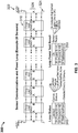
- a monitoring and communication system 300 which includes an array of sensors 310 coupled to a power bus 322, a ground line 324 and a communications bus 326.
- power bus 322 is a 12V (volt) line
- sensors array 310 is comprised of sensors 310-1, 310-2, 310-3 through sensor 310-N.
- One of the advantages of system 300 is that it provides for complete end-to-end communications and power bus loop for a fault-tolerant system. Further, full-duplex serial communications in two directions around a communications loop for fault-tolerant data communications is facilitated thereby providing complete system operation when any single fault occurs. In addition, there is a dual power supply source for fault-tolerant power distribution from both sides of the loop. This provides complete system operation when any single power wiring fault occurs.
- sensor loop diagnostics include module hardware adapted for switching the power supply on and off from each end of the loop.
- system 300 provides its location.
- system 300 provides the location of the open points.
- sensor power supply voltage monitoring and sensor LED-current for monitoring static optical blockage levels, as well as a discrete Push-Pull physical layer transceiver are optimized for cost and performance in an agricultural environment.
- Individual sensor-to-sensor link communications and periodic messages are used to continuously determine the communications health of the system.
- On-demand messages are used to determine integrity of the power bus. This is shown in a Loop Status 340 and a Loop Power Test Result 350 messages from system 300.
- system 300 is used in a Seed Blockage Sensing System such that the communication bus is used for communicating blockage data when the Seed Blockage Sensing system detects a blockage of an overall seed distribution system. Blockage data is communicated on the bus and then an alarm sounds (or any other warning signal) to advise the user that a portion of an air seeder system or a portion of a row planter system is blocked.
- 3 phototransistors and 3 photodiodes are used in the system to detect blockages such as when the planting tube becomes clogged or blocked or the seed is blown out into the ground. Blockage data is communicated to user via the bus.
- multiple LEDs are used opposite a single photodiode cell to detect blockages.
- system 300 is used in a Fertilizer Blockage System wherein the bus is applied to a sensor system detecting the blockage of a granular fertilizer distribution system. Blockage data is communicated on the bus, which is eventually communicated to the user in real-time.
- the bus is used in connection with a counting system which is monitoring seed dispensing row units. Seed counting and timing data is communicated on the bus which is delivered to the user in real-time so that adjustments can be made on a timely basis.
- the sensing element is an infrared LED with an associated light sensor to sense disruptions in the light beam. Seed count data and ground speed data are also used to make real-time adjustments in a planting system (or a fertilizer or pesticide system).
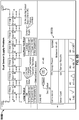
- FIGs. 4A and 4B there is shown a diagram of a state machine 400 of monitoring system (DCBS) 200 and a diagram 450 illustrating a plurality of alive messages in the different states and the transition between states of monitoring system 200.
- DCBS monitoring system
- all control modules coupled to sensor rings
- monitoring system 200 will enter a Ready state 406 or a Failed state 404 and system 200 master module (such as master module 204) will indicate this System State. If the Module Position sequence fails the state will change to Failed.
- Alive messages from master module 204 will indicate the current System State; with this being the only module which the S-ECU will communicate with in this example embodiment. If one or more modules are in Failed state 404, the entire system 200 is in a failed state and a diagnostics screen is optionally presented indicating which of the modules are in the Failed state. Command messages are defined to get the detailed status of any of the modules within the DCBS system.
- the DCBS system is designed to be able to self-initialize without any communication with the S-ECU. The last set configuration is stored in the DCBS and upon power up will configure and check against that configuration. The S-ECU is responsible for making sure the configuration is set correctly.
- the S-ECU may query the DCBS for its configuration to determine if changes are needed, or it can send the configuration on each power up.
- the DCBS will determine if the setting is different than previous and re-initialize if necessary. This will transition the state back to NotReady 402 state until initialization has completed.
- the DCBS In the NotReady state, the DCBS will perform all initializations and start up procedures based on its stored configuration. At completion the DCBS will transition into the Ready or Failed state. During initialization, if the hardware configuration does not match the stored configuration, alarms will be generated.
- ReadyState 406 the DCBS System is waiting for the System start message, which represents the inactive state of the system. Typically a lift switch is used to transition in and out of this state when the machine transitions from in and out of work.
- a RunState 408 the machine indicates that it is in the work state and will begin its blockage monitoring function and report back any blocked rows (which correspond to any blocked dispensing product units).
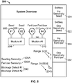
- Display 500 includes images of a Seed module 504, having a set of sensor loops 506 and 508 coupled thereto, and a Fertilizer module 510, having a set of sensor loops 512 and 514 coupled thereto.
- modules are configurable to monitor other materials that can be deposited and can clog or block the dispensing units such as pesticides, herbicides, salt, rock, and sand and the like.
- Display also includes softkeys 520 and 522 for increasing and decreasing seed blockage sensitivity, respectively, as well as softkeys 530 and 532 for increasing and decreasing fertilizer blockage sensitivity, respectively. The results are displayed as Seed Sensitivity 520A and Fertilizer Sensitivity 530A as well as blockage detection for each as 540 along with respective values for each measurement.
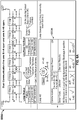
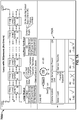
- FIGs. 6A-6C there is illustrated an example embodiment of a dual communication failure between two sets of sensors in two directions (600A-600C) and various associated user displays (650A-650C) of same according to the invention.
- a communication line open from B to A (marked by X) between sensor 42 and 43 and a communication line open from A to B (marked by X) between sensor 44 and 45.
- the sensor count has been set too low, the only one sensor fault/open is detected of 600A in display 650A.
- the sensor count is increased to 4 as in 650B then the correct number of faults are detected.
- 650C indicates the correct number of faults detected as well as all of the sensors in the circuit that are affected by the faults/opens.
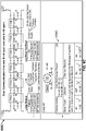
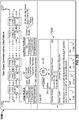
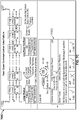
- FIGs. 7A-7D is an example of a loop with 20 sensors (700A-700D) in various states of dual communication failure between sensors and in one or two directions and various associated user displays (750A-750D) of same.
- the sensor count has been set too low, and only 10 sensors are expected but 20 sensors are found and such is indicated in display 750A as an error message and a fail state.
- Loop #2 has 20 sensors (Seed in this example as the Fertilizer feature is turned off) there is a communication line open from A to B (marked by X) between sensor 2 and 3 and a communication line open from B to A (marked by X) between sensor 19 and 20.
- Loop #2 has 20 sensors (Seed in this example as the Fertilizer feature is turned off) with the correct count being reflected in a display 750D so as to be able to detect the correct number of sensors in the loop.
- circuit 700D there is a communication line open from A to B (marked by X) between sensor 18 and 19. It appears from display 750D all of the sensor are detected and that a fault/open is detected and the correct location is also detected. All of the sensors (seed or fertilizer or whatever material is dispensed) will be used in the blockage algorithm and all of the sensors in the loop will report blocked status (see display 750D, Loop #2 is marked with a " ⁇ "), with the blockage occurring between sensors 58 and 59.
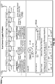
- FIG. 8A shows 6 sensors in circuit 800A (sensors 41-46) with the Seed sensor count set to 6 in Loop #2.
- a power line open (marked by X) is shown between sensors 44 and 45 and another power line open (marked by X) between sensors 45 and 46. All of the sensors (seed or fertilizer or whatever material is dispensed) will be ignored by the blockage algorithm and all of the sensors in the loop will be marked as blocked (see display 850A, Loop #2 is marked with an "X") while the Communication display will show an error and the Loop Power will show where the power line open is to be found.
- sensors are shown in circuit 800B (sensors 41-46) with the Seed sensor count set to 6 in Loop #2 (and the Fertilizer feature turned off) with a power line open (marked by X) being shown between sensors 44 and 45. All of the sensors (seed or fertilizer or whatever material is dispensed) are properly detected and counted (Sensor Count - OK); all of the sensors communicating properly (Communication - OK) and no Sensor Results are displayed.
- the Loop Power display however detects the power open line between sensors 44 and 45 in display 850B (see display 850B, Loop #2 is marked with a " ⁇ " between sensors 41-46).
- the various embodiments described above include one or more aspects of the following: complete system operation is maintained when any single fault occurs; sensor loop diagnostics provide information that can be presented to the user to aid in fault location; individual sensor diagnostics provides information that can be presented to the user to aid in pending wiring and connector problems and in determining sensor optics blockage level, which is representative of dirt accumulation or damaged optics.
- a microwave sensor is used instead of an optic sensor to sense the product being dispensed (seed, fertilizer, pesticide and the like).
- the cost of the UART transceiver is reduced from commercially available IC parts (CAN, RS-485, etc.) as the threshold voltage levels have more hysteresis than commercially available IC parts.
- the individual sensor-to-sensor communications link provides a fault-tolerant communications bus while prior art architectures would typically result in stopping all communications on the bus.
- the system user is presented with information from periodic messages to continuously monitor the communications health of the system.
- the user invokes on-demand diagnostics to determine integrity of the power bus.
- the various embodiments of the invention provide diagnostic and configuration messages not found in prior art systems.
- the virtual terminal device is a wireless device coupled to the CAN bus 9 or coupled directly to the master control module.
- the virtual terminal device can also be selected from the group consisting of a tablet, a smartphone, and a notebook PC.
Landscapes
- Engineering & Computer Science (AREA)
- Life Sciences & Earth Sciences (AREA)
- Theoretical Computer Science (AREA)
- Physics & Mathematics (AREA)
- General Physics & Mathematics (AREA)
- Soil Sciences (AREA)
- Computer Networks & Wireless Communication (AREA)
- Signal Processing (AREA)
- Quality & Reliability (AREA)
- General Engineering & Computer Science (AREA)
- Environmental Sciences (AREA)
- Mechanical Engineering (AREA)
- Health & Medical Sciences (AREA)
- Biomedical Technology (AREA)
- Fluid Mechanics (AREA)
- Automation & Control Theory (AREA)
- Human Computer Interaction (AREA)
- Catching Or Destruction (AREA)
- Testing And Monitoring For Control Systems (AREA)
- Fertilizing (AREA)
Claims (13)
- Système de surveillance de blocages et de communication tolérant aux pannes pour une unité de distribution de produits, le système comportant :au moins une unité de commande électronique périphérique (202) apte à surveiller une sortie de produits en provenance de l'unité de distribution de produits ;au moins un module de commande maître (204) apte à communiquer avec ladite au moins une unité de commande électronique périphérique (202), dans lequel ledit au moins un module de commande maître (204) inclut en outre des diagnostics de boucle de capteurs ;un bus de communication de réseau de zone de commande configuré de manière à interconnecter ladite au moins une unité de commande électronique périphérique (202) avec ledit au moins un module de commande maître (204) ; etune première pluralité d'unités de capteurs (310) ;caractérisé en ce que la première pluralité d'unités de capteurs (1-40) est configurée et connectée fonctionnellement dans une configuration en guirlande, en vue de former une boucle de capteurs (214) couplée fonctionnellement audit au moins un module de commande maître (204), chacune desdites unités de capteurs (1-40), au sein de la boucle, étant connectée à une ligne de masse (324) et à une source ou un bus d'alimentation (322) aux deux extrémités de ladite configuration en guirlande dans le système de surveillance, chacune desdites unités de capteurs (1-40) étant en outre connectée, au niveau d'une première extrémité de la boucle de capteurs (214), à une première ligne de communication, et étant connectée, au niveau d'une seconde extrémité de la boucle de capteurs (214), à une seconde ligne de communication, de manière à présenter une double communication bidirectionnelle autour d'une boucle de communication au sein de la boucle de capteurs (214) et des lignes de communication individuelles entre chaque unité de capteur (1-40), dans lequel l'alimentation et la communication entre chacune des unités de capteurs (1-40) sont maintenues lors de la survenue de l'une parmi une perte d'alimentation ou une perte de ligne de communication, sur la première ou la seconde extrémité de la boucle de capteurs (214), et dans lequel les diagnostics de boucle de capteurs dudit au moins un module de commande maître (204) fournissent un emplacement d'un défaut de câblage, d'une perte d'alimentation ou d'une perte de communication d'une pluralité de boucles de capteurs présentant une panne dans celui ou celles parmi le bus d'alimentation et les lignes de communication, dans au moins une boucle de capteurs (214).
- Système de communication tolérant aux pannes selon la revendication 1, dans lequel le module de commande maître (204) est apte à communiquer avec une deuxième pluralité d'unités de capteurs (41-80).
- Système de communication tolérant aux pannes selon la revendication 2, comprenant en outre un module de commande esclave (206) couplé fonctionnellement audit bus de communication de réseau de zone de commande, et configuré de manière à communiquer avec une troisième pluralité d'unités de capteurs (81-120).
- Système de communication tolérant aux pannes selon la revendication 1, dans lequel l'unité de distribution de produits est sélectionnée à partir du groupe constitué par un semoir, un épandeur d'engrais, un épandeur de pesticides et une unité de distribution de pesticides.
- Système de communication tolérant aux pannes selon la revendication 1, dans lequel ledit module de commande maître (204) est configuré de manière à recevoir un signal de blocage en provenance d'au moins une unité de capteur fonctionnellement couplée à l'unité de distribution de produits.
- Système de communication tolérant aux pannes selon la revendication 3, comprenant en outre une pluralité de modules de commande esclaves (206, 208) couplée au bus de communication de réseau de zone de commande auquel est couplée fonctionnellement au moins une pluralité correspondante d'unités de capteurs (81-120, 121-160) couplées dans une configuration en guirlande.
- Système de communication tolérant aux pannes selon la revendication 2, comprenant en outre un dispositif de terminal virtuel (230) fonctionnellement couplé au bus de communication de réseau de zone de commande, à ladite unité de commande électronique périphérique (202) et audit module de commande maître (204).
- Système de communication tolérant aux pannes selon la revendication 7, dans lequel le dispositif de terminal virtuel (230) est un dispositif sans fil couplé au bus de communication de réseau de zone de commande.
- Système de communication tolérant aux pannes selon la revendication 7, dans lequel le dispositif de terminal virtuel (230) est sélectionné à partir du groupe constitué par une tablette électronique, un téléphone intelligent et un ordinateur portable.
- Système de communication tolérant aux pannes selon la revendication 1, comprenant en outre un module de commande esclave (206) fonctionnellement couplé au bus de communication de réseau de zone de commande et configuré de manière à communiquer avec une deuxième pluralité d'unités de capteurs (41-81).
- Système de communication tolérant aux pannes selon la revendication 1, comprenant en outre un terminal virtuel (230) fonctionnellement couplé au bus de communication de réseau de zone de commande et audit module de commande maître (204).
- Système de communication tolérant aux pannes selon la revendication 7, dans lequel le bus de communication de réseau de zone de commande est configuré de manière à interconnecter ledit au moins un module de commande maître (204) avec le terminal virtuel (230) et un module de commande esclave (206), ledit module de commande esclave (206) étant configuré de manière à communiquer avec une deuxième pluralité d'unités de capteurs (41-80).
- Système de communication tolérant aux pannes selon la revendication 12, dans lequel au moins une unité de commande électronique périphérique (202) est apte à commander une sortie de produit distribué, à partir d'une unité de distribution de produits, et est fonctionnement couplée audit bus de communication de réseau de zone de commande.
Applications Claiming Priority (2)
| Application Number | Priority Date | Filing Date | Title |
|---|---|---|---|
| US201261584000P | 2012-01-06 | 2012-01-06 | |
| PCT/US2013/020464 WO2013103937A1 (fr) | 2012-01-06 | 2013-01-07 | Système de bus de communication de détection et de surveillance insensible aux défaillances pour applications agricoles |
Publications (3)
| Publication Number | Publication Date |
|---|---|
| EP2801031A1 EP2801031A1 (fr) | 2014-11-12 |
| EP2801031A4 EP2801031A4 (fr) | 2015-09-02 |
| EP2801031B1 true EP2801031B1 (fr) | 2017-07-19 |
Family
ID=48745469
Family Applications (1)
| Application Number | Title | Priority Date | Filing Date |
|---|---|---|---|
| EP13733907.3A Active EP2801031B1 (fr) | 2012-01-06 | 2013-01-07 | Système de bus de communication de détection et de surveillance insensible aux défaillances pour applications agricoles |
Country Status (3)
| Country | Link |
|---|---|
| US (2) | US9307694B2 (fr) |
| EP (1) | EP2801031B1 (fr) |
| WO (1) | WO2013103937A1 (fr) |
Cited By (1)
| Publication number | Priority date | Publication date | Assignee | Title |
|---|---|---|---|---|
| DE102021201877A1 (de) | 2021-02-26 | 2022-09-01 | Matthias Bußjäger | Sensordatenerfassungssystem |
Families Citing this family (18)
| Publication number | Priority date | Publication date | Assignee | Title |
|---|---|---|---|---|
| EP2901400A4 (fr) | 2013-09-23 | 2015-12-02 | Farmobile Llc | Système de collecte et d'échange de données agricoles |
| BR102013027318B1 (pt) * | 2013-10-23 | 2019-12-10 | José Roberto do Amaral Assy | processo e dispositivo para controle de falhas na dosagem de sementes em plantadeiras |
| US9320192B2 (en) | 2013-11-12 | 2016-04-26 | Dickey-John Corporation | Synchronization of a twin row planting system |
| US9672717B1 (en) * | 2013-12-27 | 2017-06-06 | Alarm.Com Incorporated | Contextual communication of events |
| JP6689203B2 (ja) | 2014-03-19 | 2020-04-28 | インテュイティブ サージカル オペレーションズ, インコーポレイテッド | 立体ビューワのための視線追跡を統合する医療システム |
| DE102015218906B4 (de) * | 2015-09-30 | 2021-06-10 | Siemens Mobility GmbH | Verfahren zum Betreiben eines Datenübertragungssystems und Datenübertragungssystem |
| US10094877B2 (en) * | 2016-02-09 | 2018-10-09 | Nasa Solutions, Llc | Method and apparatus for determining presence and operation of components in a printed circuit board |
| WO2018085422A1 (fr) * | 2016-11-01 | 2018-05-11 | Kinze Manufacturing, Inc. | Unités de commande, nœuds, système, et procédé de transmission et de communication de données |
| DE102016123539A1 (de) * | 2016-12-06 | 2018-06-07 | Horsch Maschinen Gmbh | Landwirtschaftliche Maschine |
| CN108234232B (zh) * | 2016-12-21 | 2020-10-23 | 杭州海康威视数字技术股份有限公司 | 基于总线的故障定位、环路检测方法、装置、系统及设备 |
| KR102150068B1 (ko) * | 2017-12-21 | 2020-08-31 | 주식회사 엘지화학 | 통신 진단 장치 및 방법 |
| US12298741B2 (en) * | 2019-05-31 | 2025-05-13 | Precision Planting Llc | Methods and systems for using duty cycle of sensors to determine seed or particle flow rate |
| TWI809285B (zh) | 2020-06-30 | 2023-07-21 | 廣達電腦股份有限公司 | 農場感測系統及其感測器資料校正方法 |
| CN113268097A (zh) * | 2021-05-24 | 2021-08-17 | 大气候物联网科技(广州)有限公司 | 一种农业自动化联动控制系统及其控制方法 |
| DE102021205849A1 (de) | 2021-06-10 | 2022-12-15 | Robert Bosch Gesellschaft mit beschränkter Haftung | Verfahren zur Zuweisung von IDs an Teilnehmer einer Daisy Chain-Anordnung bei landwirtschaftlichen Anwendungen |
| IT202100032750A1 (it) | 2021-12-28 | 2023-06-28 | Ynnova S R L | Apparato di rilevazione ottica per la rilevazione dei semi che transitano in un tubo di semina di una macchina seminatrice, in particolare di una seminatrice a righe. |
| IT202100032771A1 (it) | 2021-12-28 | 2023-06-28 | Ynnova S R L | Apparato di rilevazione ottica per la rilevazione dei semi che transitano in un tubo di semina di una macchina seminatrice perfezionato. |
| DE102023108168A1 (de) * | 2023-03-30 | 2024-10-02 | Amazonen-Werke H. Dreyer SE & Co. KG | Sensoranordnung für eine landwirtschaftliche Maschine |
Family Cites Families (9)
| Publication number | Priority date | Publication date | Assignee | Title |
|---|---|---|---|---|
| CA2141092C (fr) | 1995-01-25 | 1999-01-05 | James F. White | Communications entre les elements d'une machine |
| US5621666A (en) * | 1995-04-20 | 1997-04-15 | Dynavisions, Inc. | Planter monitor |
| US5809440A (en) * | 1997-02-27 | 1998-09-15 | Patchen, Inc. | Agricultural implement having multiple agents for mapping fields |
| US6009354A (en) | 1997-09-23 | 1999-12-28 | Case Corporation | Enhanced implement control |
| US7610122B2 (en) | 2005-08-16 | 2009-10-27 | Deere & Company | Mobile station for an unmanned vehicle |
| US20080262669A1 (en) | 2006-09-22 | 2008-10-23 | Jadi, Inc. | Autonomous vehicle controller |
| EP1950351A3 (fr) | 2007-01-17 | 2010-04-28 | Muncie Power Products, Inc. | Système de contrôle électrohydraulique pour véhicule |
| US8319165B2 (en) * | 2007-07-03 | 2012-11-27 | Holland Kyle H | Variable rate chemical management for agricultural landscapes |
| US7861110B2 (en) | 2008-04-30 | 2010-12-28 | Egenera, Inc. | System, method, and adapter for creating fault-tolerant communication busses from standard components |
-
2013
- 2013-01-07 US US14/370,550 patent/US9307694B2/en active Active
- 2013-01-07 EP EP13733907.3A patent/EP2801031B1/fr active Active
- 2013-01-07 WO PCT/US2013/020464 patent/WO2013103937A1/fr not_active Ceased
-
2016
- 2016-04-11 US US15/095,618 patent/US9854726B2/en active Active
Cited By (1)
| Publication number | Priority date | Publication date | Assignee | Title |
|---|---|---|---|---|
| DE102021201877A1 (de) | 2021-02-26 | 2022-09-01 | Matthias Bußjäger | Sensordatenerfassungssystem |
Also Published As
| Publication number | Publication date |
|---|---|
| US9307694B2 (en) | 2016-04-12 |
| US20140343806A1 (en) | 2014-11-20 |
| EP2801031A1 (fr) | 2014-11-12 |
| US9854726B2 (en) | 2018-01-02 |
| WO2013103937A1 (fr) | 2013-07-11 |
| EP2801031A4 (fr) | 2015-09-02 |
| US20170006765A1 (en) | 2017-01-12 |
Similar Documents
| Publication | Publication Date | Title |
|---|---|---|
| EP2801031B1 (fr) | Système de bus de communication de détection et de surveillance insensible aux défaillances pour applications agricoles | |
| US8781693B2 (en) | Method for automatic location identification of electronic devices on agricultural implements | |
| AU2018200214B2 (en) | Systems, methods and apparatus for multi-row agricultural implement control and monitoring | |
| US20230229142A1 (en) | Methods and systems for using duty cycle of sensors to determine seed or particle flow rate | |
| US6091997A (en) | Enhanced statistical/status display | |
| US6009354A (en) | Enhanced implement control | |
| US9330062B2 (en) | Vehicle control and gateway module | |
| US5621666A (en) | Planter monitor | |
| US5323721A (en) | Planter monitor system | |
| US9565798B2 (en) | Wireless flow monitoring system for an air seeder | |
| US9324197B2 (en) | Method and system for managing the hand-off between control terminals | |
| US20160246296A1 (en) | Gateway system and method | |
| EP3061334A1 (fr) | Procédé et dispositif pour éviter les erreurs de dosage de graines dans des planteuses | |
| WO2014186041A1 (fr) | Module de commande et de passerelle de véhicule | |
| US20220279705A1 (en) | Method and systems for using sensors to determine relative seed or particle speed | |
| CA2944423C (fr) | Procede et systeme pour la gestion de transfert entre des terminaux de commande | |
| US20260056345A1 (en) | Systems, methods, and apparatus for the operation of electronic components and the display of information related to agricultural implements | |
| CN109618620A (zh) | 一种双单向离合器配合的播补一体化马铃薯种植机 | |
| US20240065135A1 (en) | Multiple networks monitor | |
| WO2025215426A1 (fr) | Système et procédé de sélection et d'affichage sur un dispositif d'affichage d'une première machine de données provenant d'une deuxième machine |
Legal Events
| Date | Code | Title | Description |
|---|---|---|---|
| PUAI | Public reference made under article 153(3) epc to a published international application that has entered the european phase |
Free format text: ORIGINAL CODE: 0009012 |
|
| 17P | Request for examination filed |
Effective date: 20140718 |
|
| AK | Designated contracting states |
Kind code of ref document: A1 Designated state(s): AL AT BE BG CH CY CZ DE DK EE ES FI FR GB GR HR HU IE IS IT LI LT LU LV MC MK MT NL NO PL PT RO RS SE SI SK SM TR |
|
| DAX | Request for extension of the european patent (deleted) | ||
| RA4 | Supplementary search report drawn up and despatched (corrected) |
Effective date: 20150730 |
|
| RIC1 | Information provided on ipc code assigned before grant |
Ipc: G06F 11/00 20060101AFI20150724BHEP Ipc: A01B 79/00 20060101ALI20150724BHEP Ipc: A01C 17/00 20060101ALI20150724BHEP Ipc: A01C 7/10 20060101ALI20150724BHEP Ipc: G06F 11/20 20060101ALI20150724BHEP |
|
| 17Q | First examination report despatched |
Effective date: 20160727 |
|
| REG | Reference to a national code |
Ref country code: DE Ref legal event code: R079 Ref document number: 602013023738 Country of ref document: DE Free format text: PREVIOUS MAIN CLASS: G06F0011000000 Ipc: G06F0011070000 |
|
| GRAJ | Information related to disapproval of communication of intention to grant by the applicant or resumption of examination proceedings by the epo deleted |
Free format text: ORIGINAL CODE: EPIDOSDIGR1 |
|
| GRAP | Despatch of communication of intention to grant a patent |
Free format text: ORIGINAL CODE: EPIDOSNIGR1 |
|
| STAA | Information on the status of an ep patent application or granted ep patent |
Free format text: STATUS: GRANT OF PATENT IS INTENDED |
|
| GRAC | Information related to communication of intention to grant a patent modified |
Free format text: ORIGINAL CODE: EPIDOSCIGR1 |
|
| RIC1 | Information provided on ipc code assigned before grant |
Ipc: H04L 12/42 20060101ALI20170110BHEP Ipc: G01F 1/76 20060101ALI20170110BHEP Ipc: A01C 21/00 20060101ALI20170110BHEP Ipc: G06F 11/20 20060101ALI20170110BHEP Ipc: H04L 12/40 20060101ALI20170110BHEP Ipc: G06F 11/07 20060101AFI20170110BHEP Ipc: A01B 79/00 20060101ALI20170110BHEP Ipc: A01C 7/10 20060101ALI20170110BHEP |
|
| INTG | Intention to grant announced |
Effective date: 20170124 |
|
| GRAS | Grant fee paid |
Free format text: ORIGINAL CODE: EPIDOSNIGR3 |
|
| GRAA | (expected) grant |
Free format text: ORIGINAL CODE: 0009210 |
|
| STAA | Information on the status of an ep patent application or granted ep patent |
Free format text: STATUS: THE PATENT HAS BEEN GRANTED |
|
| AK | Designated contracting states |
Kind code of ref document: B1 Designated state(s): AL AT BE BG CH CY CZ DE DK EE ES FI FR GB GR HR HU IE IS IT LI LT LU LV MC MK MT NL NO PL PT RO RS SE SI SK SM TR |
|
| REG | Reference to a national code |
Ref country code: GB Ref legal event code: FG4D |
|
| REG | Reference to a national code |
Ref country code: CH Ref legal event code: EP |
|
| REG | Reference to a national code |
Ref country code: IE Ref legal event code: FG4D |
|
| REG | Reference to a national code |
Ref country code: AT Ref legal event code: REF Ref document number: 911018 Country of ref document: AT Kind code of ref document: T Effective date: 20170815 |
|
| REG | Reference to a national code |
Ref country code: DE Ref legal event code: R096 Ref document number: 602013023738 Country of ref document: DE |
|
| REG | Reference to a national code |
Ref country code: SE Ref legal event code: TRGR |
|
| REG | Reference to a national code |
Ref country code: NL Ref legal event code: MP Effective date: 20170719 |
|
| REG | Reference to a national code |
Ref country code: LT Ref legal event code: MG4D |
|
| REG | Reference to a national code |
Ref country code: AT Ref legal event code: MK05 Ref document number: 911018 Country of ref document: AT Kind code of ref document: T Effective date: 20170719 |
|
| REG | Reference to a national code |
Ref country code: FR Ref legal event code: PLFP Year of fee payment: 6 |
|
| PG25 | Lapsed in a contracting state [announced via postgrant information from national office to epo] |
Ref country code: LT Free format text: LAPSE BECAUSE OF FAILURE TO SUBMIT A TRANSLATION OF THE DESCRIPTION OR TO PAY THE FEE WITHIN THE PRESCRIBED TIME-LIMIT Effective date: 20170719 Ref country code: NL Free format text: LAPSE BECAUSE OF FAILURE TO SUBMIT A TRANSLATION OF THE DESCRIPTION OR TO PAY THE FEE WITHIN THE PRESCRIBED TIME-LIMIT Effective date: 20170719 Ref country code: HR Free format text: LAPSE BECAUSE OF FAILURE TO SUBMIT A TRANSLATION OF THE DESCRIPTION OR TO PAY THE FEE WITHIN THE PRESCRIBED TIME-LIMIT Effective date: 20170719 Ref country code: FI Free format text: LAPSE BECAUSE OF FAILURE TO SUBMIT A TRANSLATION OF THE DESCRIPTION OR TO PAY THE FEE WITHIN THE PRESCRIBED TIME-LIMIT Effective date: 20170719 Ref country code: NO Free format text: LAPSE BECAUSE OF FAILURE TO SUBMIT A TRANSLATION OF THE DESCRIPTION OR TO PAY THE FEE WITHIN THE PRESCRIBED TIME-LIMIT Effective date: 20171019 Ref country code: AT Free format text: LAPSE BECAUSE OF FAILURE TO SUBMIT A TRANSLATION OF THE DESCRIPTION OR TO PAY THE FEE WITHIN THE PRESCRIBED TIME-LIMIT Effective date: 20170719 |
|
| PG25 | Lapsed in a contracting state [announced via postgrant information from national office to epo] |
Ref country code: BG Free format text: LAPSE BECAUSE OF FAILURE TO SUBMIT A TRANSLATION OF THE DESCRIPTION OR TO PAY THE FEE WITHIN THE PRESCRIBED TIME-LIMIT Effective date: 20171019 Ref country code: IS Free format text: LAPSE BECAUSE OF FAILURE TO SUBMIT A TRANSLATION OF THE DESCRIPTION OR TO PAY THE FEE WITHIN THE PRESCRIBED TIME-LIMIT Effective date: 20171119 Ref country code: PL Free format text: LAPSE BECAUSE OF FAILURE TO SUBMIT A TRANSLATION OF THE DESCRIPTION OR TO PAY THE FEE WITHIN THE PRESCRIBED TIME-LIMIT Effective date: 20170719 Ref country code: ES Free format text: LAPSE BECAUSE OF FAILURE TO SUBMIT A TRANSLATION OF THE DESCRIPTION OR TO PAY THE FEE WITHIN THE PRESCRIBED TIME-LIMIT Effective date: 20170719 Ref country code: GR Free format text: LAPSE BECAUSE OF FAILURE TO SUBMIT A TRANSLATION OF THE DESCRIPTION OR TO PAY THE FEE WITHIN THE PRESCRIBED TIME-LIMIT Effective date: 20171020 Ref country code: LV Free format text: LAPSE BECAUSE OF FAILURE TO SUBMIT A TRANSLATION OF THE DESCRIPTION OR TO PAY THE FEE WITHIN THE PRESCRIBED TIME-LIMIT Effective date: 20170719 Ref country code: RS Free format text: LAPSE BECAUSE OF FAILURE TO SUBMIT A TRANSLATION OF THE DESCRIPTION OR TO PAY THE FEE WITHIN THE PRESCRIBED TIME-LIMIT Effective date: 20170719 |
|
| REG | Reference to a national code |
Ref country code: DE Ref legal event code: R097 Ref document number: 602013023738 Country of ref document: DE |
|
| PG25 | Lapsed in a contracting state [announced via postgrant information from national office to epo] |
Ref country code: CZ Free format text: LAPSE BECAUSE OF FAILURE TO SUBMIT A TRANSLATION OF THE DESCRIPTION OR TO PAY THE FEE WITHIN THE PRESCRIBED TIME-LIMIT Effective date: 20170719 Ref country code: RO Free format text: LAPSE BECAUSE OF FAILURE TO SUBMIT A TRANSLATION OF THE DESCRIPTION OR TO PAY THE FEE WITHIN THE PRESCRIBED TIME-LIMIT Effective date: 20170719 Ref country code: DK Free format text: LAPSE BECAUSE OF FAILURE TO SUBMIT A TRANSLATION OF THE DESCRIPTION OR TO PAY THE FEE WITHIN THE PRESCRIBED TIME-LIMIT Effective date: 20170719 |
|
| PLBE | No opposition filed within time limit |
Free format text: ORIGINAL CODE: 0009261 |
|
| STAA | Information on the status of an ep patent application or granted ep patent |
Free format text: STATUS: NO OPPOSITION FILED WITHIN TIME LIMIT |
|
| PG25 | Lapsed in a contracting state [announced via postgrant information from national office to epo] |
Ref country code: SK Free format text: LAPSE BECAUSE OF FAILURE TO SUBMIT A TRANSLATION OF THE DESCRIPTION OR TO PAY THE FEE WITHIN THE PRESCRIBED TIME-LIMIT Effective date: 20170719 Ref country code: EE Free format text: LAPSE BECAUSE OF FAILURE TO SUBMIT A TRANSLATION OF THE DESCRIPTION OR TO PAY THE FEE WITHIN THE PRESCRIBED TIME-LIMIT Effective date: 20170719 Ref country code: SM Free format text: LAPSE BECAUSE OF FAILURE TO SUBMIT A TRANSLATION OF THE DESCRIPTION OR TO PAY THE FEE WITHIN THE PRESCRIBED TIME-LIMIT Effective date: 20170719 |
|
| 26N | No opposition filed |
Effective date: 20180420 |
|
| PG25 | Lapsed in a contracting state [announced via postgrant information from national office to epo] |
Ref country code: SI Free format text: LAPSE BECAUSE OF FAILURE TO SUBMIT A TRANSLATION OF THE DESCRIPTION OR TO PAY THE FEE WITHIN THE PRESCRIBED TIME-LIMIT Effective date: 20170719 |
|
| REG | Reference to a national code |
Ref country code: CH Ref legal event code: PL |
|
| PG25 | Lapsed in a contracting state [announced via postgrant information from national office to epo] |
Ref country code: LU Free format text: LAPSE BECAUSE OF NON-PAYMENT OF DUE FEES Effective date: 20180107 |
|
| REG | Reference to a national code |
Ref country code: IE Ref legal event code: MM4A |
|
| REG | Reference to a national code |
Ref country code: BE Ref legal event code: MM Effective date: 20180131 |
|
| PG25 | Lapsed in a contracting state [announced via postgrant information from national office to epo] |
Ref country code: LI Free format text: LAPSE BECAUSE OF NON-PAYMENT OF DUE FEES Effective date: 20180131 Ref country code: CH Free format text: LAPSE BECAUSE OF NON-PAYMENT OF DUE FEES Effective date: 20180131 Ref country code: BE Free format text: LAPSE BECAUSE OF NON-PAYMENT OF DUE FEES Effective date: 20180131 |
|
| PG25 | Lapsed in a contracting state [announced via postgrant information from national office to epo] |
Ref country code: IE Free format text: LAPSE BECAUSE OF NON-PAYMENT OF DUE FEES Effective date: 20180107 |
|
| PG25 | Lapsed in a contracting state [announced via postgrant information from national office to epo] |
Ref country code: MC Free format text: LAPSE BECAUSE OF FAILURE TO SUBMIT A TRANSLATION OF THE DESCRIPTION OR TO PAY THE FEE WITHIN THE PRESCRIBED TIME-LIMIT Effective date: 20170719 |
|
| PG25 | Lapsed in a contracting state [announced via postgrant information from national office to epo] |
Ref country code: MT Free format text: LAPSE BECAUSE OF NON-PAYMENT OF DUE FEES Effective date: 20180107 |
|
| PG25 | Lapsed in a contracting state [announced via postgrant information from national office to epo] |
Ref country code: TR Free format text: LAPSE BECAUSE OF FAILURE TO SUBMIT A TRANSLATION OF THE DESCRIPTION OR TO PAY THE FEE WITHIN THE PRESCRIBED TIME-LIMIT Effective date: 20170719 |
|
| PG25 | Lapsed in a contracting state [announced via postgrant information from national office to epo] |
Ref country code: PT Free format text: LAPSE BECAUSE OF FAILURE TO SUBMIT A TRANSLATION OF THE DESCRIPTION OR TO PAY THE FEE WITHIN THE PRESCRIBED TIME-LIMIT Effective date: 20170719 Ref country code: HU Free format text: LAPSE BECAUSE OF FAILURE TO SUBMIT A TRANSLATION OF THE DESCRIPTION OR TO PAY THE FEE WITHIN THE PRESCRIBED TIME-LIMIT; INVALID AB INITIO Effective date: 20130107 |
|
| PG25 | Lapsed in a contracting state [announced via postgrant information from national office to epo] |
Ref country code: CY Free format text: LAPSE BECAUSE OF FAILURE TO SUBMIT A TRANSLATION OF THE DESCRIPTION OR TO PAY THE FEE WITHIN THE PRESCRIBED TIME-LIMIT Effective date: 20170719 Ref country code: MK Free format text: LAPSE BECAUSE OF NON-PAYMENT OF DUE FEES Effective date: 20170719 |
|
| PG25 | Lapsed in a contracting state [announced via postgrant information from national office to epo] |
Ref country code: AL Free format text: LAPSE BECAUSE OF FAILURE TO SUBMIT A TRANSLATION OF THE DESCRIPTION OR TO PAY THE FEE WITHIN THE PRESCRIBED TIME-LIMIT Effective date: 20170719 |
|
| PGFP | Annual fee paid to national office [announced via postgrant information from national office to epo] |
Ref country code: SE Payment date: 20231127 Year of fee payment: 12 |
|
| PGFP | Annual fee paid to national office [announced via postgrant information from national office to epo] |
Ref country code: IT Payment date: 20231212 Year of fee payment: 12 |
|
| PGFP | Annual fee paid to national office [announced via postgrant information from national office to epo] |
Ref country code: GB Payment date: 20241121 Year of fee payment: 13 |
|
| PGFP | Annual fee paid to national office [announced via postgrant information from national office to epo] |
Ref country code: FR Payment date: 20241121 Year of fee payment: 13 |
|
| PGFP | Annual fee paid to national office [announced via postgrant information from national office to epo] |
Ref country code: DE Payment date: 20241120 Year of fee payment: 13 |
|
| REG | Reference to a national code |
Ref country code: SE Ref legal event code: EUG |