EP2801157B1 - Verfahren und vorrichtung zum senden und empfangen von downlink-kanalstatusinformationen in einem mobilen kommunikationssystem - Google Patents
Verfahren und vorrichtung zum senden und empfangen von downlink-kanalstatusinformationen in einem mobilen kommunikationssystem Download PDFInfo
- Publication number
- EP2801157B1 EP2801157B1 EP12837957.5A EP12837957A EP2801157B1 EP 2801157 B1 EP2801157 B1 EP 2801157B1 EP 12837957 A EP12837957 A EP 12837957A EP 2801157 B1 EP2801157 B1 EP 2801157B1
- Authority
- EP
- European Patent Office
- Prior art keywords
- cqi
- csi
- transmission points
- control information
- determined
- Prior art date
- Legal status (The legal status is an assumption and is not a legal conclusion. Google has not performed a legal analysis and makes no representation as to the accuracy of the status listed.)
- Active
Links
Images



Classifications
-
- H—ELECTRICITY
- H04—ELECTRIC COMMUNICATION TECHNIQUE
- H04W—WIRELESS COMMUNICATION NETWORKS
- H04W72/00—Local resource management
- H04W72/50—Allocation or scheduling criteria for wireless resources
- H04W72/54—Allocation or scheduling criteria for wireless resources based on quality criteria
- H04W72/542—Allocation or scheduling criteria for wireless resources based on quality criteria using measured or perceived quality
-
- H—ELECTRICITY
- H04—ELECTRIC COMMUNICATION TECHNIQUE
- H04B—TRANSMISSION
- H04B7/00—Radio transmission systems, i.e. using radiation field
- H04B7/02—Diversity systems; Multi-antenna system, i.e. transmission or reception using multiple antennas
- H04B7/04—Diversity systems; Multi-antenna system, i.e. transmission or reception using multiple antennas using two or more spaced independent antennas
- H04B7/06—Diversity systems; Multi-antenna system, i.e. transmission or reception using multiple antennas using two or more spaced independent antennas at the transmitting station
- H04B7/0613—Diversity systems; Multi-antenna system, i.e. transmission or reception using multiple antennas using two or more spaced independent antennas at the transmitting station using simultaneous transmission
- H04B7/0615—Diversity systems; Multi-antenna system, i.e. transmission or reception using multiple antennas using two or more spaced independent antennas at the transmitting station using simultaneous transmission of weighted versions of same signal
- H04B7/0619—Diversity systems; Multi-antenna system, i.e. transmission or reception using multiple antennas using two or more spaced independent antennas at the transmitting station using simultaneous transmission of weighted versions of same signal using feedback from receiving side
- H04B7/0621—Feedback content
- H04B7/0626—Channel coefficients, e.g. channel state information [CSI]
-
- H—ELECTRICITY
- H04—ELECTRIC COMMUNICATION TECHNIQUE
- H04B—TRANSMISSION
- H04B7/00—Radio transmission systems, i.e. using radiation field
- H04B7/02—Diversity systems; Multi-antenna system, i.e. transmission or reception using multiple antennas
- H04B7/022—Site diversity; Macro-diversity
- H04B7/024—Co-operative use of antennas of several sites, e.g. in co-ordinated multipoint or co-operative multiple-input multiple-output [MIMO] systems
-
- H—ELECTRICITY
- H04—ELECTRIC COMMUNICATION TECHNIQUE
- H04B—TRANSMISSION
- H04B7/00—Radio transmission systems, i.e. using radiation field
- H04B7/02—Diversity systems; Multi-antenna system, i.e. transmission or reception using multiple antennas
- H04B7/04—Diversity systems; Multi-antenna system, i.e. transmission or reception using multiple antennas using two or more spaced independent antennas
- H04B7/06—Diversity systems; Multi-antenna system, i.e. transmission or reception using multiple antennas using two or more spaced independent antennas at the transmitting station
-
- H—ELECTRICITY
- H04—ELECTRIC COMMUNICATION TECHNIQUE
- H04B—TRANSMISSION
- H04B7/00—Radio transmission systems, i.e. using radiation field
- H04B7/02—Diversity systems; Multi-antenna system, i.e. transmission or reception using multiple antennas
- H04B7/04—Diversity systems; Multi-antenna system, i.e. transmission or reception using multiple antennas using two or more spaced independent antennas
- H04B7/06—Diversity systems; Multi-antenna system, i.e. transmission or reception using multiple antennas using two or more spaced independent antennas at the transmitting station
- H04B7/0613—Diversity systems; Multi-antenna system, i.e. transmission or reception using multiple antennas using two or more spaced independent antennas at the transmitting station using simultaneous transmission
- H04B7/0615—Diversity systems; Multi-antenna system, i.e. transmission or reception using multiple antennas using two or more spaced independent antennas at the transmitting station using simultaneous transmission of weighted versions of same signal
- H04B7/0619—Diversity systems; Multi-antenna system, i.e. transmission or reception using multiple antennas using two or more spaced independent antennas at the transmitting station using simultaneous transmission of weighted versions of same signal using feedback from receiving side
- H04B7/0621—Feedback content
- H04B7/063—Parameters other than those covered in groups H04B7/0623 - H04B7/0634, e.g. channel matrix rank or transmit mode selection
-
- H—ELECTRICITY
- H04—ELECTRIC COMMUNICATION TECHNIQUE
- H04B—TRANSMISSION
- H04B7/00—Radio transmission systems, i.e. using radiation field
- H04B7/02—Diversity systems; Multi-antenna system, i.e. transmission or reception using multiple antennas
- H04B7/04—Diversity systems; Multi-antenna system, i.e. transmission or reception using multiple antennas using two or more spaced independent antennas
- H04B7/06—Diversity systems; Multi-antenna system, i.e. transmission or reception using multiple antennas using two or more spaced independent antennas at the transmitting station
- H04B7/0613—Diversity systems; Multi-antenna system, i.e. transmission or reception using multiple antennas using two or more spaced independent antennas at the transmitting station using simultaneous transmission
- H04B7/0615—Diversity systems; Multi-antenna system, i.e. transmission or reception using multiple antennas using two or more spaced independent antennas at the transmitting station using simultaneous transmission of weighted versions of same signal
- H04B7/0619—Diversity systems; Multi-antenna system, i.e. transmission or reception using multiple antennas using two or more spaced independent antennas at the transmitting station using simultaneous transmission of weighted versions of same signal using feedback from receiving side
- H04B7/0621—Feedback content
- H04B7/0632—Channel quality parameters, e.g. channel quality indicator [CQI]
-
- H—ELECTRICITY
- H04—ELECTRIC COMMUNICATION TECHNIQUE
- H04B—TRANSMISSION
- H04B7/00—Radio transmission systems, i.e. using radiation field
- H04B7/02—Diversity systems; Multi-antenna system, i.e. transmission or reception using multiple antennas
- H04B7/04—Diversity systems; Multi-antenna system, i.e. transmission or reception using multiple antennas using two or more spaced independent antennas
- H04B7/06—Diversity systems; Multi-antenna system, i.e. transmission or reception using multiple antennas using two or more spaced independent antennas at the transmitting station
- H04B7/0613—Diversity systems; Multi-antenna system, i.e. transmission or reception using multiple antennas using two or more spaced independent antennas at the transmitting station using simultaneous transmission
- H04B7/0615—Diversity systems; Multi-antenna system, i.e. transmission or reception using multiple antennas using two or more spaced independent antennas at the transmitting station using simultaneous transmission of weighted versions of same signal
- H04B7/0619—Diversity systems; Multi-antenna system, i.e. transmission or reception using multiple antennas using two or more spaced independent antennas at the transmitting station using simultaneous transmission of weighted versions of same signal using feedback from receiving side
- H04B7/0636—Feedback format
- H04B7/0639—Using selective indices, e.g. of a codebook, e.g. pre-distortion matrix index [PMI] or for beam selection
-
- H—ELECTRICITY
- H04—ELECTRIC COMMUNICATION TECHNIQUE
- H04W—WIRELESS COMMUNICATION NETWORKS
- H04W72/00—Local resource management
- H04W72/20—Control channels or signalling for resource management
- H04W72/23—Control channels or signalling for resource management in the downlink direction of a wireless link, i.e. towards a terminal
Definitions
- the present invention relates generally to a mobile communication system, and more particularly, to a method and apparatus for transmitting and receiving downlink (DL) channel state information (CSI) in a mobile communication system.
- DL downlink
- CSI channel state information
- a mobile communication system has evolved into a high speed and high quality wireless packet data communication system to provide data and multimedia services.
- Various mobile communication standards such as HSDPA (high speed downlink packet access), HSUPA (high speed uplink packet access), LTE (long term evolution), and LTE-A (long term evolution advanced) of 3GPP (3rd generation partnership project), HRPD (high rate packet data) of 3GPP2, and 802.16 of IEEE (institute of electrical and electronics engineers) have recently been developed to support high speed and high quality wireless packet data transmission services.
- the LTE system which is a system developed to efficiently support high speed wireless packet data transmission, maximizes wireless system capacity by using various wireless access technologies.
- the LTE-A system which is a wireless system evolved from the LTE system, has an enhanced data transmission capability as compared to the LTE system.
- the existing 3rd generation wireless packet data communication system such as HSDPA, HSUPA, or HRPD employs technologies for improving transmission efficiency, such as an adaptive modulation and coding (AMC) scheme and a channel response scheduling scheme.
- AMC adaptive modulation and coding
- a transmitter may adjust the amount of transmitted data according to a channel state. That is, a transmitter may efficiently transmit a large amount of information while adjusting the probability of erroneous reception to a desired level by reducing the amount of transmitted data when a channel state is poor and increasing the amount of transmitted data when a channel state is good.
- the channel response scheduling scheme system capacity is increased as compared to the prior art schemes because a transmitter selectively provides a service to a user having a good channel state among multiple users. Such an increase in system capacity is called multiuser diversity.
- the AMC scheme and the channel response scheduling scheme allow a transmitter to receive feedback of partial channel state information from a receiver and apply an appropriate modulation and coding technique at a point of time determined to be most efficient.
- the AMC scheme may also include a function of determining the number of spatial layers for a transmitted signal, that is, a rank, when being used with a multiple input multiple output (MIMO) transmission scheme.
- MIMO multiple input multiple output
- a transmitter in determining an optimal data rate, a transmitter considers not only a coding rate and a modulation scheme, but also the number of layers to be used for MIMO transmission.
- CDMA code division multiple access
- OFDMA orthogonal frequency division multiple access
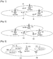
- a mobile communication service using a non-coordinated multi-point (non-CoMP) transmission/reception scheme is conventionally provided by a cellular system including multiple cells implemented as shown in FIG. 1 .
- FIG. 1 illustrates a conventional mobile communication system including three cells, each of which has a transmission/reception antenna disposed at its center.
- An Enhanced node B (eNB) 1, 10, 20 is disposed in each cell, and thus data transmission/reception may be performed between the eNB 1, 10, 20 and a user equipment (UE) 30, 40, 50 existing in a corresponding cell. That is, the UE0 30 existing in the coverage of the cell 0 receives a physical downlink shared channel (PDSCH) from the eNB 1.
- PDSCH physical downlink shared channel
- the cell 1 and the cell 2 also transmit data signals to the UE1 40 and the UE2 50 by using the same time and frequency resources respectively.
- the data transmission in the cell 0, the cell 1, or the cell 2 corresponds to the non-CoMP transmission scheme in which radio resources in one cell are used only for a UE within the corresponding cell.
- the UE When one UE receives a signal from one cell or transmission point, as shown in FIG. 1 , the UE sets a cell or transmission point, from which it is to receive the signal, in advance through radio resource control (RRC) signaling. Also, the UE transmits channel state information (CSI) for a downlink channel, that is, downlink CSI (DL-CSI), only to the set cell or transmission point.
- RRC radio resource control
- CSI channel state information
- the CSI includes information on the data rate supportable by the UE, information on the precoder preferred by the UE, and information on the number of spatial layers, that is, a rank, supportable by the UE in MIMO transmission
- US 2010/271968 A1 discloses method for a user equipment to transmit CQ1 feedback information to an evolved Node B in a wireless communication system wherein one or more Transmission Points Configurations for Coordinated Multipoint (CoMP) (TPCCs) are obtained, each TPCC including a unique combination of one or more cells in a CoMP measurement set, computing a CQ1 for the configured TPCCs, generating and finally transmitting CQ1 feedback information based on the CQls to enable CoMP joint transmission (JT).
- CoMP Coordinated Multipoint
- Transmission from one transmission point to one UE, as shown in FIG. 1 has a limitation on the receivable data rate when the UE is far away from the transmission point or is subjected to strong interference from neighboring transmission points.
- an aspect of the present invention is to solve at least the above-described problems occurring in the prior art, and to provide at least the advantages described below.
- Another aspect of the present invention is to provide a method and apparatus for transmitting and receiving downlink channel state information (DL-CSI) in a mobile communication system.
- DL-CSI downlink channel state information
- Yet another aspect of the present invention is to provide a method and apparatus for transmitting and receiving DL-CSI in order to efficiently use radio resources when a UE receives downlink channels from multiple transmission points.
- a method for transmitting channel state information (CSI) by a user equipment (UE) in a mobile communication system includes receiving a CSI-reference signal (CSI-RS) for measuring a state of a downlink channel and a CSI feedback-related configuration from a base station (BS); determining a channel quality indication (CQI) for at least one transmission point and control information for determining a CQI for multiple transmission points, based on the received CSI-RS and CSI feedback-related configuration; and transmitting the determined CQI for the at least one transmission point and control information to the BS.
- CSI-RS CSI-reference signal
- CQI channel quality indication
- a method for receiving channel state information (CSI) by a base station (BS) in a mobile communication system includes transmitting a CSI-reference signal (CSI-RS) for measuring a state of a downlink channel and a CSI feedback-related configuration to a user equipment (UE); and receiving a channel quality indication (CQI) for at least one transmission point and control information for determining a CQI for multiple transmission points, which are determined based on the transmitted CSI-RS and CSI feedback-related configuration, from the UE.
- CSI-RS CSI-reference signal
- CQI channel quality indication
- an apparatus for transmitting channel state information (CSI) by a user equipment (UE) in a mobile communication system.
- the apparatus includes a receiver for receiving a CSI-reference signal (CSI-RS) for measuring a state of a downlink channel and a CSI feedback-related configuration from a base station (BS); a controller for determining a channel quality indication (CQI) for at least one transmission point and control information for determining a CQI for multiple transmission points, based on the received CSI-RS and CSI feedback-related configuration; and a transmitter for transmitting the determined CQI for the at least one transmission point and control information to the BS.
- CSI-RS CSI-reference signal
- CQI channel quality indication
- an apparatus for receiving channel state information (CSI) by a base station (BS) in a mobile communication system.
- the apparatus includes a transmitter for transmitting a CSI-reference signal (CSI-RS) for measuring a state of a downlink channel and a CSI feedback-related configuration to a user equipment (UE); and a receiver for receiving a channel quality indication (CQI) for at least one transmission point and control information for determining a CQI for multiple transmission points, which are determined based on the transmitted CSI-RS and CSI feedback-related configuration, from the UE.
- CSI-RS CSI-reference signal
- CQI channel quality indication
- a method for transmitting channel state information (CSI) by a user equipment (UE) in a mobile communication system includes receiving a CSI-reference signal (CSI-RS) for measuring a state of a downlink channel and a CSI feedback-related configuration from a base station (BS); determining rank indicators (RIs) and precoding matrix indicators (PMIs) for respective transmission points, based on the received CSI-RS and CSI feedback-related configuration; and transmitting the determined RIs and PMIs for the respective transmission points.
- CSI-RS CSI-reference signal
- BS base station
- RIs rank indicators
- PMIs precoding matrix indicators
- a method for receiving channel state information (CSI) by a base station (BS) in a mobile communication system includes transmitting a CSI-reference signal (CSI-RS) for measuring a state of a downlink channel and a CSI feedback-related configuration to a user equipment (UE); receiving rank indicators (RIs) and precoding matrix indicators (PMIs) for respective transmission points, which are determined based on the transmitted CSI-RS and CSI feedback-related configuration, from the UE; and determining an RI for multiple transmission points based on the RIs for the respective transmission points, and combining precoding matrices indicated by the PMIs for the respective transmission points according to the determined RI.
- CSI-RS CSI-reference signal
- PMIs precoding matrix indicators
- an apparatus for transmitting channel state information (CSI) by a user equipment (UE) in a mobile communication system.
- the apparatus includes a receiver for receiving a CSI-reference signal (CSI-RS) for measuring a state of a downlink channel and a CSI feedback-related configuration from a base station (BS); a controller for determining rank indicators (RIs) for respective transmission points and precoding matrix indicator (PMI) for the respective transmission points, based on the received CSI-RS and CSI feedback-related configuration; and a transmitter for transmitting the determined RIs and PMIs for the respective transmission points.
- CSI-RS CSI-reference signal
- PMI precoding matrix indicator
- an apparatus for receiving channel state information (CSI) by a base station (BS) in a mobile communication system.
- the apparatus includes a transmitter for transmitting a CSI-reference signal (CSI-RS) for measuring a state of a downlink channel and a CSI feedback-related configuration to a user equipment (UE); a receiver for receiving rank indicators (RIs) and precoding matrix indicators (PMIs) for respective transmission points, which are determined based on the transmitted CSI-RS and CSI feedback-related configuration, from the UE; and a controller for determining an RI for multiple transmission points based on the RIs for the respective transmission points, and combining precoding matrices indicated by the PMIs for the respective transmission points according to the determined RI.
- CSI-RS CSI-reference signal
- PMIs precoding matrix indicators
- an OFDM-based mobile communication system in particular, the 3GPP EUTRA standard
- the main gist of the present invention may be applied to other communication systems with similar technical backgrounds and channel types by slightly modifying them according to the understanding those skilled in the art without departing from the scope of the present invention.
- FIG. 2 illustrates a CoMP scheme in which transmission/reception is performed in the presence of collaboration between eNBs of respective cells in a mobile communication system.
- a central controller for collectively controlling eNBs 100, 110, 120 is provided, and the central controller performs determinations related to the CoMP scheme.
- FIG. 3 illustrates a CoMP scheme in which transmission/reception is performed in the presence of collaboration between different transmission points in the same cell.
- FIG. 3 there are four transmission points 200, 210, 220, 230 sharing one cell ID. Also, two transmission points 200, 230 of the four transmission points simultaneously transmit PDSCHs to UE1 250, and the other two transmission points 210, 220 simultaneously transmit PDSCHs to UE0 240.
- a central controller for collectively controlling the four transmission points 200, 210, 220, 230 is also provided in FIG. 3 , and the central controller performs determinations related to the CoMP scheme.
- JT Joint transmission
- a UE transmits information on a downlink channel to the central controller in such a manner that the UE transmits individual channel state information (CSI) for multiple cells or transmission points.
- CSI channel state information
- FIG. 2 upon receiving PDSCHs simultaneously transmitted from the cells 0 and 1, the UE0 130 transmits CSI for the cell 0 and CSI for the cell 1 respectively.
- FIG. 3 upon receiving PDSCHs simultaneously transmitted from the transmission points 210, 220, the UE0 240 SI for the transmission point 210 and CSI for the transmission point 220 respectively.
- FIG. 4 illustrates radio resources of a downlink channel in an LTE/LTE-A system.
- the radio resources shown in FIG. 4 correspond to one physical resource block (PRB) pair in the frequency domain and one subframe (1 msec) in the time domain.
- PRB physical resource block
- one PRB pair within one subframe includes 14 OFDM symbols in the time domain and 12 subcarriers in the frequency domains.
- One subcarrier within one OFDM symbol is defined as a resource element (RE)
- REs constituting one PRB pair carry signals for performing different functions according to their positions in the PRB pair.
- CRSs cell specific reference signals
- DMRSs demodulation reference signals
- PDSCHs control channels, and the like are transmitted according to the positions of REs.
- a CSI-reference signal (CSI-RS) is transmitted in order to allow a UE to measure the state of a downlink channel.
- CSI-RS CSI-reference signal
- multiple CS-RSs may be set in order to measure the states of downlink channels for individual cells or transmission points.
- "300" of FIG. 4 may be set for a CSI-RS transmitted from the cell 0 of FIG. 2
- "310" of FIG. 4 may be set for a CSI-RS transmitted form the cell 1 of FIG. 2 .
- a UE may measure individual downlink channels by allocating individual radio resources to CSI-RSs transmitted from different cells or transmission points.
- the central controller upon receiving CSI for individual cells or transmission points from a UE, the central controller infers channels states, which are to occur when JT is performed, from the multiple individual CSI.
- the UE0 130 informs the central controller that it can receive a data rate of A kbps from the cell 0 and receive a data rate of B kbps from the cell 1.
- the central controller determines at which data rate radio resources are most efficiently used to transmit PDSCHs to the UE0 130 when JT from the cell 0 and the cell 1 is performed.
- the central controller determines that it is efficient to transmit a data rate of 300 kbps to the UE0 when JT from the cell 0 and the cell 1 is performed. Determining a data rate, the number of spatial layers, or the like related to PDSCH transmission by using CSI for individual cells or transmission points, as described above, has a disadvantage in that it cannot properly reflect the actual channel conditions occurring when JT from multiple cells or transmission points to a UE is performed.
- a central controller does not know the structure of a receiver of a UE in determining DL-CSI transmitted from the UE to the central controller.
- the relation between individual CSI and complex CSI for JT from multiple cells or transmission points varies according to how the structure of a receiver of a UE is implemented.
- a central controller does not know how the structure of a receiver of a UE is implemented, it is difficult for the corresponding central controller to accurately determine the relation between individual CSI and complex CSI for JT from multiple cells or transmission points, which may cause errors.
- control information ⁇ CQI that makes it possible to infer complex CSI is defined as follows:
- the control information ⁇ CQI is relative information regarding a channel quality indicator (CQI), which a UE transmits in order to indicate complex CSI.
- the CQI is information on a maximum data rate that a UE can support while maintaining a reception error rate at a certain level, and in the case of LTE/LTE-A, is sent from a UE to an eNB by using 4 bits.
- the CQI in the LTE/LTE-A system is defined as summarized below in Table 1.
- CQI index Modulation code rate 1024 efficiency 0 out of range 1 QPSK 78 0.1523 2 QPSK 120 0.2344 3 QPSK 193 0.3770 4 QPSK 308 0.6016 5 QPSK 449 0.8770 6 QPSK 602 1.1758 7 16QAM 378 1.4766 8 16QAM 490 1.9141 9 16QAM 616 2.4063 10 64QAM 466 2.7305 11 64QAM 567 3.3223 12 G4QAM 666 3.9023 13 64QAM 772 4.5234 14 64QAM 873 5.1152 15 64QAM 948 5.5547
- a UE transmits individual CQIs for two cells or transmission points, that is, CQI 1 and CQI 2 , in uplink.
- the data rate receivable by the same UE corresponds to at least the greater value of CQI 1 and CQI 2 .
- CQI 12 denotes the data rate receivable by a UE when two cells or transmission points simultaneously transmit.
- a UE transmits ⁇ CQI in uplink instead of CQI 12 .
- Transmission of ⁇ CQI instead of CQI 12 has an advantage in that a relatively few bits are required for the transmission. As an example, in the LTE/LTE-A system, 4 bits are required to transmit the CQI, but only 2 bits are required to transmit ⁇ CQI .
- ⁇ CQI The specific meaning of ⁇ CQI must be shared between the UE and the eNB or central controller, and the meaning of ⁇ CQI proposed in embodiments of the present invention is determined as shown below in Table 2.
- CQI value meaning associated with CQI 12 00 CQI 12 is the same as max( CQI 1 , CQI 2 ) 01 CQI 12 is a CQI value that is higher by one step than max( CQI 1 , CQI 2 ) 10 CQI 12 is a CQI value that is higher by two steps than max( CQI 1 , CQI 2 ). 11 CQI 12 is a CQI value that is higher by three steps than max( CQI 1 , CQI 2 ).
- ⁇ CQI is so designed as to assign CQI 12 to a value of at least max(CQI 1 ,CQI 2 ) or greater. This results from the fact that when two cells or transmission points supporting CQI 1 and CQI 2 respectively perform JT, a data rate of at least max(CQI 1 ,CQI 2 ) can be supported, as described above.
- Table 2 corresponds to the case where 2 bits are used to indicate ⁇ CQI .
- 1 bit is used to indicate ⁇ CQI .
- the meaning of ⁇ CQI may be determined as shown below in Table 3.
- M is a value that is set between an eNB or central controller and a UE in advance, and other values may also be applied in consideration of the channel environment and the like.
- Equations (1) and (2) and Tables 2 and 3 all relate to a case where the number of cells or transmission points performing JT is 2. This may also be applied in the same manner when any number of cells or transmission points perform JT.
- CQI JT corresponds to a data rate receivable by a UE when cell 1 to cell N perform JT.
- Table 4 below which is the modified form of Table 2, may be applied.
- CQI JT is the same as max( CQI 1 ,...,CQI N ) 01
- CQI JT is a CQI value that is higher by one step than max( CQI 1 ,..., CQI N )
- CQI JT is a CQI value that is higher by two steps than max( CQI 1 ,...., CQI N )
- CQI JT is a CQI value that is higher by three steps than max( CQI 1 ,..., CQI N )
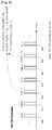
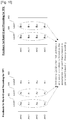
- FIG. 5 illustrates an example of transmitting control information ⁇ CQI by a UE according to an embodiment of the present invention.
- this example corresponds to a case where UE CSI feedback is periodic in nature.
- information is carried by a physical uplink control channel (PUCCH) of the LTE/LTE-A system.
- PUCCH physical uplink control channel
- the periodic CSI feedback allows a UE to periodically perform CSI feedback only by one-time setting.
- CSI feedback is performed at periodic points of time as indicated by reference numerals "400", "410", “420", “430”, “440”, “450”, and “460”, and different CSI may be transmitted at each point of time when the CSI feedback is transmitted.
- the CSI may include a rank indicator (RI) informing of how many spatial layers a UE supports, a precoding matrix indicator (PMI) informing of which precoding a UE prefers, and a CQI informing of which data rate a UE can receive. Also, as described above, the CSI feedback is separately performed for each cell or transmitted point.
- the control information ⁇ CQI proposed in the present invention may be transmitted together with an individual CQI for a specific cell or transmission point, as shown at 450 of FIG. 5 . Upon receiving ⁇ CQI at 450 of FIG.
- an eNB or central controller determines a CQI, which is to occur when JT is performed, by using ⁇ CQI and individual CQIs (CQI TP1 , CQI TP2 ) at 420 and 450 of FIG. 5 .
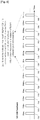
- FIG. 6 illustrates another example of transmitting control information ⁇ CQI by a UE according to an embodiment of the present invention.
- this example corresponds to a case where UE CSI feedback is periodic in nature.
- information is carried by a PUCCH of the LTE/LTE-A system.
- CSI feedback is separately performed for each cell or transmission point.
- the control information ⁇ CQI proposed in the present invention is transmitted together whenever an individual CQI is transmitted as shown at 520, 550, and 580 of FIG. 6 .
- ⁇ CQI which is to occur when JT is performed, is transmitted to an eNB or central controller at relatively short periods, which makes it possible for the eNB or central controller to more efficiently use radio resources.
- an eNB or central controller determines a CQI, which is to occur when JT is performed, by using ⁇ CQI and individual CQIs (CQI TP1 , CQI TP2 ) at 520 and 550 of FIG. 6 .
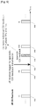
- FIG. 7 illustrates yet another example of transmitting control information ⁇ CQI by a UE according to an embodiment of the present invention.
- this example corresponds to a case where UE CSI feedback is periodic in nature.
- information is carried by a PUCCH of the LTE/LTE-A system.
- CSI feedback is separately performed for each cell or transmission point.
- the control information ⁇ CQI proposed in the present invention is transmitted together whenever an individual CQI is transmitted as shown at 620, 650, and 680 of FIG. 7 .
- ⁇ CQI is transmitted such that two of three cells or transmission points may perform JT.
- ⁇ CQI_B transmitted at 620 and 680 of FIG. 7 indicates how much higher a data rate receivable by a UE is than max(CQI TP2 ,CQI TP3 ) when transmission point 2 and transmission point 3 perform JT.
- ⁇ CQI_C transmitted at 650 and 680 of FIG. 7 indicates how much higher a data rate receivable by a UE is than max(CQI TP1 ,CQI TP3 ) when transmission point 1 and transmission point 3 perform JT.
- ⁇ CQI is determined and transmitted on the assumption that two of three transmission points perform JT.
- individual CQIs considered in ⁇ CQI transmitted at a specific point of time correspond to a COI for an individual transmission point, which is transmitted together at that point of time when ⁇ CQI is transmitted, and a CQI for an individual transmission point, which has been transmitted before that point of time. That is, ⁇ CQI_A and ⁇ CQI_B transmitted at 650 of FIG. 7 are all determined using CQI TP2 transmitted at 650 and CQI TP1 ,CQI TP3 transmitted before 650.
- FIG. 8 illustrates still yet another example of transmitting control information ⁇ CQI by a UE according to an embodiment of the present invention.
- this example corresponds to a case where UE CSI feedback is periodic in nature.
- information is carried by a PUCCH of the LTE/LTE-A system.
- CSI feedback is separately performed for each cell or transmission point.
- the control information ⁇ CQI proposed in the present invention is transmitted together whenever an individual phase indicator (PHI) is transmitted, as shown at 730 and 765 of FIG. 8 .
- the PHI is used to indicate with which phase difference a cell or transmission point is to transmit a signal in order to provide coherent combining.
- This PHI is information required when coherent joint transmission (coherent JT) is performed, and generally has an information amount of 2 to 3 bits.
- a UE transmits ⁇ CQI and a PHI at the same point of time is that these two information are all associated with JT and an eNB or central controller necessarily requires all the two information for coherent JT.
- Control information transmitted at each point of time of transmission has a probability of causing a reception error, but JT can be supported only when ⁇ CQI and a PHI are all received without reception errors.
- it is necessary to minimize the probability that any one of ⁇ CQI and a PHI causes a reception error and in this view, it is advantageous to transmit these two information at the same point of time, as shown in FIG. 8 .
- ⁇ CQI is determined based on the greatest value of multiple CQI values.
- another determination method proposed in the present invention is to determine ⁇ CQI based on a specific CQI value when ⁇ CQI is transmitted together with the corresponding CQI value, as shown in FIG. 5 or FIG. 6 .
- a UE transmits ⁇ CQI and CQI TP1 at 520 of FIG. 6 , and transmits ⁇ CQI and CQI TP2 at 550 of FIG. 6 .
- ⁇ CQI transmitted at 550 of FIG. 6 is used to indicate how much higher a CQI for JT is than CQI TP2 .
- FIG. 9 illustrates still yet another example of transmitting control information ⁇ CQI by a UE according to an embodiment of the present invention.
- this example corresponds to a case where a UE performs aperiodic CSI feedback under instructions of an eNB or central controller while performing periodic CSI feedback.
- CSI feedback is separately performed for each cell or transmission point.
- information is carried by a PUCCH of the LTE/LTE-A system.
- information is carried by a PUSCH.
- CSI feedback transmitted at 800, 810, 840, and 850 of FIG. 9 corresponds to the periodic CSI feedback performed at periodic points of time. Contrarily, CSI feedback transmitted at 830 of FIG.
- Reference numeral "820" of FIG. 9 indicates an aperiodic CSI feedback trigger that is carried by a PDCCH from an eNB to a UE.
- the aperiodic CSI feedback of FIG. 9 may include individual CSI feedback for one or multiple cells or transmission points according to its settings.
- the aperiodic CSI feedback may include the following information:
- ⁇ CQI of the aperiodic CSI feedback information 1 is determined by Equation (1) or (3), based on individual CQIs (CQI TP1 ,CQI TP2 ) for transmission point 1 and transmission point 2.
- the aperiodic CSI feedback may include the following information:
- ⁇ CQI of the aperiodic CSI feedback information 2 is determined by Equation (1) or (3), based on CQI information for transmission point 1 (or cell 1), which is included in the aperiodic feedback, and CQI information for transmission point 2 (or cell 2), which has been transmitted before the aperiodic CSI feedback.
- FIG. 5 , FIG. 6 , FIG. 7 , FIG. 8 , and FIG. 9 it is assumed that one individual CQI is transmitted for one cell or transmission point.
- a signal may be transmitted from one cell or transmission point to a UE by multiple spatial layers.
- a signal is transmitted by multiple spatial layers in the LTE/LET-A system in this way, a UE transmits two CQIs for one cell or transmission point. Transmitting two CQIs for one cell or transmission point is intended to support accurate AMC for two codewords transmitted by different spatial layers.
- the UE transmits the above-mentioned RI to an eNB and thereby informs the eNB how many spatial layers it can support.
- the number of spatial layers that is, a rank, is used in the same meaning as the number of MIMO signals.
- Situation 1 corresponds to the control method transmission methods proposed in the present invention, which have been described in connection with FIG. 5 , FIG. 6 , FIG.7 , FIG. 8, and FIG. 8 , so a detailed description thereof will be omitted here.
- Situation 2 corresponds to a case where a UE may receive at least two spatial layers from different cells or transmission points.
- a UE for each cell or transmission point, a UE must transmit two CQIs for two codewords.
- a UE transmits individual ⁇ CQI for each codeword and thereby allows multiple cells or transmission points to perform JT.
- ⁇ CQI (CW0) for a first codeword is obtained using Equation (1) or (3), based on CQI values for transmission point 1 and transmission point 2, that is, CQI CW0TP1 and CQI CW0TP2 , which a UE transmits for the first codeword.
- ⁇ CQI (CW1) for a second codeword is obtained using Equation (1) or (3), based on CQI values for transmission point 1 and transmission point 2, that is, CQI CW1TP1 and CQI CW1TP2 , which a UE transmits for the second codeword.
- a UE when a UE informs an eNB that it can support different numbers of spatial layers for multiple cells or transmission points, the eNB determines the number of spatial layers, which are to be transmitted through JT, by using the following equation without any separate additional control information:
- Equations (5) and (6) it can be noted that the number of spatial layers to be transmitted through JT is the minimum value of individual ranks for multiple cells or transmission points.
- the number of spatial layers of a signal to be transmitted through JT is determined using Equations (5) and (6) proposed in the present invention, there is an advantage in that a UE does not need to transmit any additional information other than rank information for each cell or transmission point to an eNB. Whether or not to apply Equations (5) and (6) is determined not through RRC signaling, but through prearranged appointments.
- Equations (5) and (6) when Equations (5) and (6) are used, a UE determines ⁇ CQI and the like according to the results of Equations (5) and (6), and an eNB or central controller assumes that ⁇ CQI and the like have been determined according to the results of Equations (5) and (6).
- a UE informs an eNB of its preferred precoding by transmitting a precoding matrix indicator (PMI) to the eNB.
- PMI precoding matrix indicator
- a UE must transmit individual PMIs for multiple cells or transmission points. Codeword to layer mapping in the LTE/LTEA system is summarized below in Table 5.
- an eNB when a UE transmits individual PMIs, an eNB can determine precoding to be applied to JT by using PHI information in a case where individual RIs transmitted by the UE for respective cells or transmission points have the same value. Contrarily, in a case where individual RIs transmitted by a UE for respective cells or transmission points have different values, an eNB determines a rank for JT by the minimum value of individual ranks, as described above. In this case, there is a problem with how to assume precoding for JT when the individual ranks are greater than the determined rank for JT. As a solution to this problem, a UE may separately transmit control information on precoding for JT, but this solution has a disadvantage in that additional uplink overhead is caused. To solve the above problem, the present invention proposes to assume a part of a precoding matrix indicated by an individual PMI as precoding for JT by using a prearranged method.
- FIG. 10 illustrates a method for determining a part of a precoding matrix indicated by an individual PMI as precoding for JT.
- the number of vertical lines of each precoding matrix corresponds to the number of spatial layers, that is, a rank.
- the number of horizontal lines of each precoding matrix corresponds to the number of transmission antennas.
- each of column vectors constituting each precoding corresponds to precoding for a signal transmitted by one spatial layer. In the case of FIG.
- the UE and the eNB assume the rank for JT (from transmission points 1 and 2) as 2 (the minimum value of the individual ranks) according to the rank determination method.
- the rank for JT from transmission points 1 and 2) as 2 (the minimum value of the individual ranks) according to the rank determination method.
- the present invention proposes to select column vectors according to a prearranged method without transmitting any additional control information.
- ⁇ CQI transmitted by a UE is determined based on precoding determined by the prearranged method.
- an eNB can know which precoding is selected to apply the determined ⁇ CQI when JT is performed, only by individual PMI information without any separate control information from the UE. Table 6 below summarizes how to determine a part of a precoding matrix indicated by an individual PMI as precoding for JT.
- TP means a transmission point.
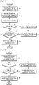
- FIG. 11 illustrates an operation of an eNB according to an embodiment of the present invention, in which the eNB sets UE CSI feedback and determines CSI for JT by using CSI feedback transmitted by a UE in order to perform JT according to an embodiment of the present invention.
- the eNB determines a CSI-RE-related configuration for allowing a UE to measure a downlink channel state and a CSI feedback-related configuration for transmitting CSI by the UE having measured CSI-RSs.
- the eNB transmits the determined CS-RS-related configuration and CI feedback-related configuration to the UE through UE-specific RRC signaling.
- the eNB also informs the UE whether or not the corresponding UE is a UE to receive CoMP signals through JT and how the corresponding UE is to transmit JT-related CSI feedback when the UE is a CoMP UE.
- the eNB receives CSI feedback from the UE.
- the eNB checks if the UE is a CoMP UE. The eNB proceeds to step 1040 when the UE is not a CoMP UE, and proceeds to step 1050 when the UE is a CoMP UE.
- the eNB identifies a CQI, a PMI, and an RI for one cell or transmission point through the received CSI feedback.
- the eNB determines if the received CSI feedback includes control information for performing JT.
- the eNB proceeds to step 1060 when the received CSI feedback does not include control information for performing JT, and proceeds to step 1070 when the received CSI feedback includes control information for performing JT.
- the eNB identifies CQIs, PMIs, and RIs for individual cells or transmission points through the received CSI feedback.
- the eNB identifies a CQI, a PMI, and an RI for performing JT from multiple cells or transmission points through the received CSI feedback.
- FIG. 12 illustrates an operation of a UE according to an embodiment of the present invention, in which the UE transmits CSI feedback for JT under instructions of an eNB in order to perform JT according to an embodiment of the present invention.
- the UE receives a CSI-RS-related configuration and a CSI feedback-related configuration from the eNB through UE-specific RRC signaling.
- the UE is also informed whether or not the UE is a UE to receive CoMP signals through JT and whether or not the UE is to transmit CSI feedback for JT when the UE is a CoMP UE.
- step 1110 the UE checks if it is a CoMP UE.
- the UE proceeds to step 1120 when it is not a CoMP UE, and proceeds to step 1130 when it is a CoMP UE.
- the UE transmits CSI feedback including a CQI, a PMI, and an RI for one cell or transmission point to the eNB.
- the UE checks if it is to transmit CSI feedback for JT.
- the UE proceeds to step 1140 when it does not transmit CSI feedback for JT, and proceeds to step 1150 when it transmits CSI feedback for JT.
- the CSI feedback for JT may be performed at periodic points of time, and may also be performed in the form of aperiodic CSI feedback under instructions of the eNB.
- the UE transmits CSI feedback including a CQI, a PMI, and an RI for multiple cells or transmission points to the eNB.
- the UE transmits CSI feedback including CQIs, PMIs, and RIs for individual cells or transmission points to the eNB.
- each of the eNB and the UE includes a transmitter unit, a receiver unit, and a controller unit, and each unit performs the above operations according to embodiments of the present invention.
Landscapes
- Engineering & Computer Science (AREA)
- Computer Networks & Wireless Communication (AREA)
- Signal Processing (AREA)
- Physics & Mathematics (AREA)
- Mathematical Physics (AREA)
- Quality & Reliability (AREA)
- Mobile Radio Communication Systems (AREA)
Claims (14)
- Verfahren zum Übertragen von Kanalzustandsinformationen, CSI, durch ein Benutzergerät, UE, in einem mobilen Kommunikationssystem, wobei das Verfahren Folgendes umfasst:Empfangen (1100) eines CSI-Referenzsignals, CSI-RS, das zum Messen eines Downlink-Kanals verwendet wird, und Konfigurationsinformationen in Bezug auf das CSI-Feedback von einer Basisstation, BS;Bestimmen einer Kanalqualitätsanzeige, CQI, für jeden der mindestens zwei Übertragungspunkte und Steuerinformationen in Bezug auf eine CQI für gemeinsame Übertragung der mindestens zwei Übertragungspunkte basierend auf dem CSI-RS und den Konfigurationsinformationen in Bezug auf das CSI-Feedback; undÜbertragen (1150) der bestimmten CQIs und der bestimmten Steuerinformationen an die BS,dadurch gekennzeichnet, dass
die Steuerinformationen einen relativen Wert umfassen, der einen Unterschied zwischen einem CQI-Wert, der eine Datenrate bezeichnet, die durch das UE empfangbar ist, wenn die mindestens zwei Übertragungspunkte gleichzeitig übertragen, und einer größten CQI unter den bestimmten CQIs anzeigt. - Verfahren zum Empfangen von Kanalzustandsinformationen, CSI, durch eine Basisstation, BS, in einem mobilen Kommunikationssystem, wobei das Verfahren Folgendes umfasst:Übertragen (1010) eines CSI-Referenzsignals, CSI-RS, das zum Messen eines Downlink-Kanals verwendet wird, und Konfigurationsinformationen in Bezug auf das CSI-Feedback an ein Benutzergerät, UE;Empfangen (1020) einer Kanalqualitätsanzeige, CQI, für jeden des mindestens einen Übertragungspunkts und Steuerinformationen in Bezug auf eine CQI für gemeinsame Übertragung der mindestens zwei Übertragungspunkte, die basierend auf dem CSI-RS und den Konfigurationsinformationen in Bezug auf das CSI-Feedback bestimmt werden, von dem UE; undEmpfangen der bestimmten CQIs und der bestimmten Steuerinformationen von dem UE;dadurch gekennzeichnet, dass
die Steuerinformationen einen relativen Wert umfassen, der einen Unterschied zwischen einem CQI-Wert, der eine Datenrate bezeichnet, die durch das UE empfangbar ist, wenn die mindestens zwei Übertragungspunkte gleichzeitig übertragen, und einer größten CQI unter den bestimmten CQIs anzeigt. - Verfahren nach Anspruch 1 oder 2, wobei die Steuerinformationen durch eine folgende Gleichung bestimmt werden,

- Vorrichtung zum Übertragen von Kanalzustandsinformationen, CSI, durch ein Benutzergerät, UE, in einem mobilen Kommunikationssystem, wobei die Vorrichtung Folgendes umfasst:einen Empfänger, der zum Empfangen eines CSI-Referenzsignals, CSI-RS, das zum Messen eines Downlink-Kanals verwendet wird, und Konfigurationsinformationen in Bezug auf die auf das CSI-Feedback bezogene Konfiguration von einer Basisstation, BS, konfiguriert ist;eine Steuerung, die zum Bestimmen einer Kanalqualitätsanzeige, CQI, für jeden der mindestens zwei Übertragungspunkte und Steuerinformationen in Bezug auf eine CQI für gemeinsame Übertragung der mindestens zwei Übertragungspunkte basierend auf dem CSI-RS und den Konfigurationsinformationen in Bezug auf das CSI-Feedback konfiguriert ist; undeinen Sender, der zum Übertragen der bestimmten CQIs und der bestimmten Steuerinformationen an die BS konfiguriert ist,dadurch gekennzeichnet, dass
die Steuerinformationen einen relativen Wert umfassen, der einen Unterschied zwischen einem CQI-Wert, der eine Datenrate bezeichnet, die durch das UE empfangbar ist, wenn die mindestens zwei Übertragungspunkte gleichzeitig übertragen, und einer größten CQI unter den bestimmten CQIs anzeigt. - Vorrichtung zum Empfangen von Kanalzustandsinformationen, CSI, durch eine Basisstation, BS, in einem mobilen Kommunikationssystem, wobei die Vorrichtung Folgendes umfasst:einen Sender, der zum Übertragen eines CSI-Referenzsignals, CSI-RS, das zum Messen eines Downlink-Kanals verwendet wird, und Konfigurationsinformationen in Bezug auf das CSI-Feedback an ein Benutzergerät, UE, konfiguriert ist; undeinen Empfänger, der zum Empfangen einer Kanalqualitätsanzeige, CQI, für jeden des mindestens einen Übertragungspunkts und Steuerinformationen in Bezug auf eine CQI für gemeinsame Übertragung der mindestens zwei Übertragungspunkte, die basierend auf dem CSI-RS und den Konfigurationsinformationen in Bezug auf das CSI-Feedback bestimmt werden, von dem UE konfiguriert ist,wobei der Empfänger zum Empfangen der bestimmten CQIs und der bestimmten Steuerinformationen von dem UE konfiguriert ist; unddadurch gekennzeichnet, dass
die Steuerinformationen einen relativen Wert umfassen, der einen Unterschied zwischen einem CQI-Wert, der eine Datenrate bezeichnet, die durch das UE empfangbar ist, wenn die mindestens zwei Übertragungspunkte gleichzeitig übertragen, und einer größten CQI unter den bestimmten CQIs anzeigt. - Vorrichtung nach Anspruch 4 oder 5, wobei die Steuerinformationen durch eine folgende Gleichung bestimmt werden,

- Verfahren zum Übertragen von Kanalzustandsinformationen, CSI, durch ein Benutzergerät, UE, in einem mobilen Kommunikationssystem, wobei das Verfahren Folgendes umfasst:Empfangen (1100) eines CSI-Referenzsignals, CSI-RS, das zum Messen eines Downlink-Kanals verwendet wird, und Konfigurationsinformationen in Bezug auf das CSI-Feedback von einer Basisstation, BS;Bestimmen von Rangindikatoren, Rls, und Vorcodierungsmatrixindikatoren, PMIs, für jeden der mindestens zwei Übertragungspunkte und Steuerinformationen in Bezug auf eine CQI für gemeinsame Übertragung der mindestens zwei Übertragungspunkte basierend auf dem CSI-RS und den Konfigurationsinformationen in Bezug auf das CSI-Feedback; undÜbertragen (1150) der bestimmten Rls, PMIs und Steuerinformationen an die BS,dadurch gekennzeichnet, dass
die Steuerinformationen einen relativen Wert umfassen, der einen Unterschied zwischen einem CQI-Wert, der eine Datenrate bezeichnet, die durch das UE empfangbar ist, wenn die mindestens zwei Übertragungspunkte gleichzeitig übertragen, und einer größten CQI der CQIs für jeden der mindestens zwei Übertragungspunkte anzeigt. - Verfahren zum Empfangen von Kanalzustandsinformationen, CSI, durch eine Basisstation, BS, in einem mobilen Kommunikationssystem, wobei das Verfahren Folgendes umfasst:Übertragen (1010) eines CSI-Referenzsignals, CSI-RS, das zum Messen eines Downlink-Kanals verwendet wird, und Konfigurationsinformationen in Bezug auf das CSI-Feedback an ein Benutzergerät, UE;Empfangen (1020) von Rangindikatoren, Rls, und Vorcodierungsmatrixindikatoren, PMIs, für jeden der mindestens zwei Übertragungspunkte und Steuerinformationen in Bezug auf eine CQI für gemeinsame Übertragung der mindestens zwei Übertragungspunkte, die basierend auf dem CSI-RS und den Konfigurationsinformationen in Bezug auf das CSI-Feedback bestimmt werden, von dem UE; undBestimmen eines RI für die mindestens zwei Übertragungspunkte basierend auf den Rls für jeden der mindestens zwei Übertragungspunkte, und Kombinieren von Vorcodierungsmatrizen, die durch die PMIs angezeigt werden, für jeden der mindestens zwei Übertragungspunkte basierend auf dem bestimmten RI,dadurch gekennzeichnet, dass
die Steuerinformationen einen relativen Wert umfassen, der einen Unterschied zwischen einem CQI-Wert, der eine Datenrate bezeichnet, die durch das UE empfangbar ist, wenn die mindestens zwei Übertragungspunkte gleichzeitig übertragen, und einer größten CQI der CQIs für jeden der mindestens zwei Übertragungspunkte anzeigt. - Verfahren nach Anspruch 7 oder 8, wobei der RI für die mindestens zwei Übertragungspunkte basierend auf einem kleinsten RI der Rls für jeden der mindestens zwei Übertragungspunkte bestimmt wird.
- Verfahren nach Anspruch 8, wobei das Kombinieren der Vorcodierungsmatrizen das Kombinieren von Teilspalten von den Vorcodierungsmatrizen, die durch die PMIs angezeigt werden, für jeden der mindestens zwei Übertragungspunkte basierend auf dem bestimmten RI umfasst, wenn die Rls für jeden der mindestens zwei Übertragungspunkte verschieden sind.
- Vorrichtung zum Übertragen von Kanalzustandsinformationen, CSI, durch ein Benutzergerät, UE, in einem mobilen Kommunikationssystem, wobei die Vorrichtung Folgendes umfasst:einen Empfänger, der zum Empfangen eines CSI-Referenzsignals, CSI-RS, das zum Messen eines Downlink-Kanals verwendet wird, und Konfigurationsinformationen in Bezug auf das CSI-Feedback von einer Basisstation, BS, konfiguriert ist;eine Steuerung, die zum Bestimmen von Rangindikatoren, Rls, für entsprechende Übertragungspunkte und eines Vorcodierungsmatrixindikators, PMI, für jeden der mindestens zwei Übertragungspunkte und Steuerinformationen in Bezug auf eine CQI für gemeinsame Übertragung der mindestens zwei Übertragungspunkte basierend auf dem CSI-RS und den Konfigurationsinformationen in Bezug auf das CSI-Feedback konfiguriert ist; undeinen Sender, der zum Übertragen der bestimmten Rls, PMIs und Steuerinformationen an die Basisstation konfiguriert ist,dadurch gekennzeichnet, dass die Steuerinformationen einen relativen Wert umfassen, der einen Unterschied zwischen einem CQI-Wert, der eine Datenrate bezeichnet, die durch das UE empfangbar ist, wenn die mindestens zwei Übertragungspunkte gleichzeitig übertragen, und einer größten CQI der CQIs anzeigt.
- Vorrichtung zum Empfangen von Kanalzustandsinformationen, CSI, durch eine Basisstation (BS) in einem mobilen Kommunikationssystem, wobei die Vorrichtung Folgendes umfasst:einen Sender, der zum Übertragen eines CSI-Referenzsignals, CSI-RS, das zum Messen eines Downlink-Kanals verwendet wird, und Konfigurationsinformationen in Bezug auf das CSI-Feedback an ein Benutzergerät, UE, konfiguriert ist;einen Empfänger, der zum Empfangen von Rangindikatoren, Rls, und Vorcodierungsmatrixindikatoren, PMIs, für jeden der mindestens zwei Übertragungspunkte und Steuerinformationen in Bezug auf eine CQI für gemeinsame Übertragung der mindestens zwei Übertragungspunkte, die basierend auf dem CSI-RS und den Konfigurationsinformationen in Bezug auf das CSI-Feedback bestimmt werden, von dem UE konfiguriert ist; undeine Steuerung, die zum Bestimmen eines RI für die mindestens zwei Übertragungspunkte basierend auf den Rls für jeden der mindestens zwei Übertragungspunkte, und Kombinieren von Vorcodierungsmatrizen, die durch die PMIs angezeigt werden, für jeden der mindestens zwei Übertragungspunkte basierend auf dem bestimmten RI konfiguriert ist,dadurch gekennzeichnet, dass
die Steuerinformationen einen relativen Wert umfassen, der einen Unterschied zwischen einem CQI-Wert, der eine Datenrate bezeichnet, die durch das UE empfangbar ist, wenn die mindestens zwei Übertragungspunkte gleichzeitig übertragen, und einer größten CQI der CQIs anzeigt. - Vorrichtung nach Anspruch 11 oder 12, wobei der RI für die mindestens zwei Übertragungspunkte basierend auf einem kleinsten RI der Rls für jeden der mindestens zwei Übertragungspunkte bestimmt wird.
- Vorrichtung nach Anspruch 12, wobei die Steuerung Teilspalten von den Vorcodierungsmatrizen, die durch die PMIs angezeigt werden, für jeden der mindestens zwei Übertragungspunkte basierend auf dem bestimmten RI kombiniert, wenn die Rls für jeden der mindestens zwei Übertragungspunkte verschieden sind.
Applications Claiming Priority (2)
| Application Number | Priority Date | Filing Date | Title |
|---|---|---|---|
| KR1020110102670A KR20130038044A (ko) | 2011-10-07 | 2011-10-07 | 이동통신시스템에서 하향링크 채널의 채널상태정보를 송수신하는 방법 및 장치 |
| PCT/KR2012/008080 WO2013051886A2 (en) | 2011-10-07 | 2012-10-05 | Method and appratus for transmitting and receiving downlink channel state information in a mobile communication system |
Publications (3)
| Publication Number | Publication Date |
|---|---|
| EP2801157A2 EP2801157A2 (de) | 2014-11-12 |
| EP2801157A4 EP2801157A4 (de) | 2015-09-30 |
| EP2801157B1 true EP2801157B1 (de) | 2020-03-11 |
Family
ID=48044310
Family Applications (1)
| Application Number | Title | Priority Date | Filing Date |
|---|---|---|---|
| EP12837957.5A Active EP2801157B1 (de) | 2011-10-07 | 2012-10-05 | Verfahren und vorrichtung zum senden und empfangen von downlink-kanalstatusinformationen in einem mobilen kommunikationssystem |
Country Status (4)
| Country | Link |
|---|---|
| US (1) | US10390352B2 (de) |
| EP (1) | EP2801157B1 (de) |
| KR (1) | KR20130038044A (de) |
| WO (1) | WO2013051886A2 (de) |
Families Citing this family (19)
| Publication number | Priority date | Publication date | Assignee | Title |
|---|---|---|---|---|
| US8797966B2 (en) | 2011-09-23 | 2014-08-05 | Ofinno Technologies, Llc | Channel state information transmission |
| CN103166734B (zh) * | 2011-12-14 | 2017-08-25 | 华为技术有限公司 | 信道状态信息的获取方法及装置 |
| US8885569B2 (en) | 2011-12-19 | 2014-11-11 | Ofinno Technologies, Llc | Beamforming signaling in a wireless network |
| KR102115901B1 (ko) * | 2013-04-16 | 2020-05-27 | 삼성전자 주식회사 | 프리코딩 관련 신호 송수신 방법 및 장치 |
| WO2015032038A1 (zh) | 2013-09-04 | 2015-03-12 | 华为技术有限公司 | 信道测量方法、终端设备及基站 |
| CN105324953B (zh) * | 2013-09-16 | 2020-11-06 | 华为技术有限公司 | 下行信道预编码矩阵的确定方法、基站和用户设备 |
| CN110401472B (zh) * | 2014-09-17 | 2021-03-09 | 上海朗帛通信技术有限公司 | 一种3d mimo传输方法和装置 |
| CN104301975B (zh) * | 2014-11-06 | 2018-04-06 | 东南大学 | 基于多点协作传输模式选择的网络节能方法 |
| GB2539269A (en) * | 2015-06-12 | 2016-12-14 | Nec Corp | Communication system |
| US10129906B2 (en) * | 2016-03-01 | 2018-11-13 | Samsung Electronics Co., Ltd. | Partial port hybrid CSI feedback for MIMO wireless communication systems |
| US10110284B2 (en) | 2016-11-03 | 2018-10-23 | At&T Intellectual Property I, L.P. | Providing a format indicator comprising rank indication and channel state information spatial domain resolution type |
| CN111741474B (zh) * | 2019-03-25 | 2022-02-11 | 华为技术有限公司 | 一种信道状态信息的测量方法、装置及网络侧设备 |
| CN110486971B (zh) * | 2019-08-29 | 2021-08-24 | 上海理工大学 | 波浪形叠层微通道制冷器 |
| CN110486973B (zh) * | 2019-08-29 | 2021-08-24 | 上海理工大学 | 具有中间入口的多级预冷微通道节流换热制冷器 |
| CN110486974B (zh) * | 2019-08-29 | 2021-08-24 | 上海理工大学 | 具有中间入口的二级叠层交错微通道节流换热制冷器 |
| CN110486980B (zh) * | 2019-08-29 | 2021-08-24 | 上海理工大学 | 微通道节流制冷器 |
| CN110486972B (zh) * | 2019-08-29 | 2021-08-24 | 上海理工大学 | 多级两侧预冷叠层交错微通道节流换热制冷器 |
| CN110486979B (zh) * | 2019-08-29 | 2021-08-24 | 上海理工大学 | 多级单侧预冷的叠层交错微通道节流换热制冷器 |
| CN110486970B (zh) * | 2019-08-29 | 2021-08-24 | 上海理工大学 | 多级单侧预冷的叠层微通道节流换热制冷器 |
Family Cites Families (12)
| Publication number | Priority date | Publication date | Assignee | Title |
|---|---|---|---|---|
| US20150030058A9 (en) * | 2006-05-17 | 2015-01-29 | Texas Instruments Inc. | Cqi feedback for mimo deployments |
| JP4229173B2 (ja) * | 2006-11-22 | 2009-02-25 | トヨタ自動車株式会社 | 動力出力装置、それを備えた自動車、および動力出力装置の制御方法 |
| US8027301B2 (en) | 2007-01-24 | 2011-09-27 | The Board Of Trustees Of The Leland Stanford Junior University | Cooperative OFDMA and distributed MIMO relaying over dense wireless networks |
| KR101387532B1 (ko) * | 2007-12-26 | 2014-04-21 | 엘지전자 주식회사 | 협력적 mimo 수행을 위한 피드백 정보 전송방법 |
| JP5450638B2 (ja) | 2008-10-30 | 2014-03-26 | アルカテル−ルーセント | マルチセクタ協調通信における協調タイプの切り替え技術 |
| US8917707B2 (en) * | 2009-04-24 | 2014-12-23 | Samsung Electronics Co., Ltd. | Techniques for channel state information feedback in wireless communication system |
| US8711716B2 (en) * | 2009-06-19 | 2014-04-29 | Texas Instruments Incorporated | Multiple CQI feedback for cellular networks |
| US9030949B2 (en) * | 2009-07-27 | 2015-05-12 | Samsung Electronics Co., Ltd. | Downlink PMI coordination based on base station antenna configuration |
| US8526413B2 (en) | 2009-10-02 | 2013-09-03 | Mediatek Inc. | Concatenating precoder selection for OFDMA-based multi-BS MIMO |
| US8824384B2 (en) | 2009-12-14 | 2014-09-02 | Samsung Electronics Co., Ltd. | Systems and methods for transmitting channel quality information in wireless communication systems |
| CN103119873B (zh) * | 2010-02-12 | 2017-04-12 | 黑莓有限公司 | 用于协作多点网络实现的参考信号 |
| US8437705B2 (en) * | 2010-10-11 | 2013-05-07 | Sharp Laboratories Of America, Inc. | Resource allocation and encoding for channel quality indicator (CQI) and CQI collided with uplink acknowledgment/negative acknowledgment |
-
2011
- 2011-10-07 KR KR1020110102670A patent/KR20130038044A/ko not_active Ceased
-
2012
- 2012-10-05 EP EP12837957.5A patent/EP2801157B1/de active Active
- 2012-10-05 US US14/349,875 patent/US10390352B2/en active Active
- 2012-10-05 WO PCT/KR2012/008080 patent/WO2013051886A2/en not_active Ceased
Non-Patent Citations (1)
| Title |
|---|
| None * |
Also Published As
| Publication number | Publication date |
|---|---|
| WO2013051886A2 (en) | 2013-04-11 |
| WO2013051886A3 (en) | 2013-07-04 |
| KR20130038044A (ko) | 2013-04-17 |
| US10390352B2 (en) | 2019-08-20 |
| US20140269596A1 (en) | 2014-09-18 |
| EP2801157A2 (de) | 2014-11-12 |
| EP2801157A4 (de) | 2015-09-30 |
Similar Documents
| Publication | Publication Date | Title |
|---|---|---|
| EP2801157B1 (de) | Verfahren und vorrichtung zum senden und empfangen von downlink-kanalstatusinformationen in einem mobilen kommunikationssystem | |
| US11064506B2 (en) | Method and apparatus for transmitting and receiving feedback for cooperative communication system | |
| CN106105052B (zh) | 用于在无线通信系统中报告信道状态信息的装置及方法 | |
| EP2897316B1 (de) | Verfahren und vorrichtung zur bestimmung von kanalstatusinformationen | |
| KR101953961B1 (ko) | 적응성 복조 기준 신호 송신을 지원하기 위한 피드백의 사용자 장비 생성 및 시그널링 | |
| EP3327941B1 (de) | Verfahren und vorrichtung zum senden und empfangen von feedbackinformationen der interzellularen kooperativen übertragung in einem zellularen drahtloskommunikationssystem | |
| KR101504446B1 (ko) | 채널 품질 지시 정보를 확정하는 방법 및 장치 | |
| US8817647B2 (en) | Priority rules of periodic CSI reporting in carrier aggregation | |
| EP2853040B1 (de) | Referenzsignalmessverfahren und vorrichtung zur verwendung in einem drahtlosen kommunikationssystem mit mehreren basisstationen mit verteilten antennen | |
| JP5645962B2 (ja) | 無線通信システムのチャンネル品質情報送信システム及び方法 | |
| KR101978776B1 (ko) | 다수의 안테나를 사용하는 이동통신 시스템에서 피드백 송수신 방법 및 장치 | |
| CN102291213B (zh) | 一种计算信道质量指示信息的终端及方法 | |
| US10771140B2 (en) | Selective channel feedback method and apparatus for use in wireless communication system | |
| EP2665220B1 (de) | Verfahren und benutzergerät zur rückkopplung von kanalstatusinformationen | |
| KR101972945B1 (ko) | 무선 통신 시스템에서 채널 상태 정보 송수신 방법 및 장치 | |
| KR101541636B1 (ko) | 원격 라디오 헤드에 의한 무선 통신 방법 및 시스템 | |
| EP2579495B1 (de) | Verfahren und Vorrichtung zum Erzeugen von Feedback in einem Kommunikationssystem | |
| KR20140038120A (ko) | 이동통신 시스템에서 피드백 송수신 방법 및 장치 | |
| US20130301447A1 (en) | Method and System for Reporting Feedback in Cooperative Multipoint Transmission | |
| KR20150070925A (ko) | 전차원 다중입력 다중출력 이동통신 시스템에서 통신방법 및 장치 | |
| CN102307083A (zh) | 信道状态信息的非周期反馈及其调度方法、装置及系统 | |
| KR102115901B1 (ko) | 프리코딩 관련 신호 송수신 방법 및 장치 | |
| EP2850742B1 (de) | Berechnung und meldung von kanaleigenschaften | |
| HK1229095A1 (en) | User equipment generation and signaling of feedback for supporting adaptive demodulation reference signal transmission |
Legal Events
| Date | Code | Title | Description |
|---|---|---|---|
| PUAI | Public reference made under article 153(3) epc to a published international application that has entered the european phase |
Free format text: ORIGINAL CODE: 0009012 |
|
| 17P | Request for examination filed |
Effective date: 20140507 |
|
| AK | Designated contracting states |
Kind code of ref document: A2 Designated state(s): AL AT BE BG CH CY CZ DE DK EE ES FI FR GB GR HR HU IE IS IT LI LT LU LV MC MK MT NL NO PL PT RO RS SE SI SK SM TR |
|
| DAX | Request for extension of the european patent (deleted) | ||
| A4 | Supplementary search report drawn up and despatched |
Effective date: 20150827 |
|
| RIC1 | Information provided on ipc code assigned before grant |
Ipc: H04J 11/00 20060101ALI20150821BHEP Ipc: H04B 7/06 20060101ALI20150821BHEP Ipc: H04B 7/04 20060101AFI20150821BHEP |
|
| STAA | Information on the status of an ep patent application or granted ep patent |
Free format text: STATUS: EXAMINATION IS IN PROGRESS |
|
| 17Q | First examination report despatched |
Effective date: 20180118 |
|
| GRAP | Despatch of communication of intention to grant a patent |
Free format text: ORIGINAL CODE: EPIDOSNIGR1 |
|
| STAA | Information on the status of an ep patent application or granted ep patent |
Free format text: STATUS: GRANT OF PATENT IS INTENDED |
|
| INTG | Intention to grant announced |
Effective date: 20191220 |
|
| GRAS | Grant fee paid |
Free format text: ORIGINAL CODE: EPIDOSNIGR3 |
|
| GRAA | (expected) grant |
Free format text: ORIGINAL CODE: 0009210 |
|
| STAA | Information on the status of an ep patent application or granted ep patent |
Free format text: STATUS: THE PATENT HAS BEEN GRANTED |
|
| AK | Designated contracting states |
Kind code of ref document: B1 Designated state(s): AL AT BE BG CH CY CZ DE DK EE ES FI FR GB GR HR HU IE IS IT LI LT LU LV MC MK MT NL NO PL PT RO RS SE SI SK SM TR |
|
| REG | Reference to a national code |
Ref country code: GB Ref legal event code: FG4D |
|
| REG | Reference to a national code |
Ref country code: CH Ref legal event code: EP |
|
| REG | Reference to a national code |
Ref country code: AT Ref legal event code: REF Ref document number: 1244452 Country of ref document: AT Kind code of ref document: T Effective date: 20200315 |
|
| REG | Reference to a national code |
Ref country code: IE Ref legal event code: FG4D |
|
| REG | Reference to a national code |
Ref country code: DE Ref legal event code: R096 Ref document number: 602012068457 Country of ref document: DE |
|
| PG25 | Lapsed in a contracting state [announced via postgrant information from national office to epo] |
Ref country code: FI Free format text: LAPSE BECAUSE OF FAILURE TO SUBMIT A TRANSLATION OF THE DESCRIPTION OR TO PAY THE FEE WITHIN THE PRESCRIBED TIME-LIMIT Effective date: 20200311 Ref country code: NO Free format text: LAPSE BECAUSE OF FAILURE TO SUBMIT A TRANSLATION OF THE DESCRIPTION OR TO PAY THE FEE WITHIN THE PRESCRIBED TIME-LIMIT Effective date: 20200611 Ref country code: RS Free format text: LAPSE BECAUSE OF FAILURE TO SUBMIT A TRANSLATION OF THE DESCRIPTION OR TO PAY THE FEE WITHIN THE PRESCRIBED TIME-LIMIT Effective date: 20200311 |
|
| REG | Reference to a national code |
Ref country code: NL Ref legal event code: MP Effective date: 20200311 |
|
| PG25 | Lapsed in a contracting state [announced via postgrant information from national office to epo] |
Ref country code: GR Free format text: LAPSE BECAUSE OF FAILURE TO SUBMIT A TRANSLATION OF THE DESCRIPTION OR TO PAY THE FEE WITHIN THE PRESCRIBED TIME-LIMIT Effective date: 20200612 Ref country code: BG Free format text: LAPSE BECAUSE OF FAILURE TO SUBMIT A TRANSLATION OF THE DESCRIPTION OR TO PAY THE FEE WITHIN THE PRESCRIBED TIME-LIMIT Effective date: 20200611 Ref country code: HR Free format text: LAPSE BECAUSE OF FAILURE TO SUBMIT A TRANSLATION OF THE DESCRIPTION OR TO PAY THE FEE WITHIN THE PRESCRIBED TIME-LIMIT Effective date: 20200311 Ref country code: SE Free format text: LAPSE BECAUSE OF FAILURE TO SUBMIT A TRANSLATION OF THE DESCRIPTION OR TO PAY THE FEE WITHIN THE PRESCRIBED TIME-LIMIT Effective date: 20200311 Ref country code: LV Free format text: LAPSE BECAUSE OF FAILURE TO SUBMIT A TRANSLATION OF THE DESCRIPTION OR TO PAY THE FEE WITHIN THE PRESCRIBED TIME-LIMIT Effective date: 20200311 |
|
| REG | Reference to a national code |
Ref country code: LT Ref legal event code: MG4D |
|
| PG25 | Lapsed in a contracting state [announced via postgrant information from national office to epo] |
Ref country code: NL Free format text: LAPSE BECAUSE OF FAILURE TO SUBMIT A TRANSLATION OF THE DESCRIPTION OR TO PAY THE FEE WITHIN THE PRESCRIBED TIME-LIMIT Effective date: 20200311 |
|
| PG25 | Lapsed in a contracting state [announced via postgrant information from national office to epo] |
Ref country code: PT Free format text: LAPSE BECAUSE OF FAILURE TO SUBMIT A TRANSLATION OF THE DESCRIPTION OR TO PAY THE FEE WITHIN THE PRESCRIBED TIME-LIMIT Effective date: 20200805 Ref country code: CZ Free format text: LAPSE BECAUSE OF FAILURE TO SUBMIT A TRANSLATION OF THE DESCRIPTION OR TO PAY THE FEE WITHIN THE PRESCRIBED TIME-LIMIT Effective date: 20200311 Ref country code: LT Free format text: LAPSE BECAUSE OF FAILURE TO SUBMIT A TRANSLATION OF THE DESCRIPTION OR TO PAY THE FEE WITHIN THE PRESCRIBED TIME-LIMIT Effective date: 20200311 Ref country code: SK Free format text: LAPSE BECAUSE OF FAILURE TO SUBMIT A TRANSLATION OF THE DESCRIPTION OR TO PAY THE FEE WITHIN THE PRESCRIBED TIME-LIMIT Effective date: 20200311 Ref country code: RO Free format text: LAPSE BECAUSE OF FAILURE TO SUBMIT A TRANSLATION OF THE DESCRIPTION OR TO PAY THE FEE WITHIN THE PRESCRIBED TIME-LIMIT Effective date: 20200311 Ref country code: IS Free format text: LAPSE BECAUSE OF FAILURE TO SUBMIT A TRANSLATION OF THE DESCRIPTION OR TO PAY THE FEE WITHIN THE PRESCRIBED TIME-LIMIT Effective date: 20200711 Ref country code: EE Free format text: LAPSE BECAUSE OF FAILURE TO SUBMIT A TRANSLATION OF THE DESCRIPTION OR TO PAY THE FEE WITHIN THE PRESCRIBED TIME-LIMIT Effective date: 20200311 Ref country code: SM Free format text: LAPSE BECAUSE OF FAILURE TO SUBMIT A TRANSLATION OF THE DESCRIPTION OR TO PAY THE FEE WITHIN THE PRESCRIBED TIME-LIMIT Effective date: 20200311 |
|
| REG | Reference to a national code |
Ref country code: AT Ref legal event code: MK05 Ref document number: 1244452 Country of ref document: AT Kind code of ref document: T Effective date: 20200311 |
|
| REG | Reference to a national code |
Ref country code: DE Ref legal event code: R097 Ref document number: 602012068457 Country of ref document: DE |
|
| PLBE | No opposition filed within time limit |
Free format text: ORIGINAL CODE: 0009261 |
|
| STAA | Information on the status of an ep patent application or granted ep patent |
Free format text: STATUS: NO OPPOSITION FILED WITHIN TIME LIMIT |
|
| PG25 | Lapsed in a contracting state [announced via postgrant information from national office to epo] |
Ref country code: ES Free format text: LAPSE BECAUSE OF FAILURE TO SUBMIT A TRANSLATION OF THE DESCRIPTION OR TO PAY THE FEE WITHIN THE PRESCRIBED TIME-LIMIT Effective date: 20200311 Ref country code: DK Free format text: LAPSE BECAUSE OF FAILURE TO SUBMIT A TRANSLATION OF THE DESCRIPTION OR TO PAY THE FEE WITHIN THE PRESCRIBED TIME-LIMIT Effective date: 20200311 Ref country code: IT Free format text: LAPSE BECAUSE OF FAILURE TO SUBMIT A TRANSLATION OF THE DESCRIPTION OR TO PAY THE FEE WITHIN THE PRESCRIBED TIME-LIMIT Effective date: 20200311 Ref country code: AT Free format text: LAPSE BECAUSE OF FAILURE TO SUBMIT A TRANSLATION OF THE DESCRIPTION OR TO PAY THE FEE WITHIN THE PRESCRIBED TIME-LIMIT Effective date: 20200311 |
|
| 26N | No opposition filed |
Effective date: 20201214 |
|
| PG25 | Lapsed in a contracting state [announced via postgrant information from national office to epo] |
Ref country code: PL Free format text: LAPSE BECAUSE OF FAILURE TO SUBMIT A TRANSLATION OF THE DESCRIPTION OR TO PAY THE FEE WITHIN THE PRESCRIBED TIME-LIMIT Effective date: 20200311 Ref country code: SI Free format text: LAPSE BECAUSE OF FAILURE TO SUBMIT A TRANSLATION OF THE DESCRIPTION OR TO PAY THE FEE WITHIN THE PRESCRIBED TIME-LIMIT Effective date: 20200311 |
|
| REG | Reference to a national code |
Ref country code: CH Ref legal event code: PL |
|
| PG25 | Lapsed in a contracting state [announced via postgrant information from national office to epo] |
Ref country code: LU Free format text: LAPSE BECAUSE OF NON-PAYMENT OF DUE FEES Effective date: 20201005 Ref country code: MC Free format text: LAPSE BECAUSE OF FAILURE TO SUBMIT A TRANSLATION OF THE DESCRIPTION OR TO PAY THE FEE WITHIN THE PRESCRIBED TIME-LIMIT Effective date: 20200311 |
|
| REG | Reference to a national code |
Ref country code: BE Ref legal event code: MM Effective date: 20201031 |
|
| PG25 | Lapsed in a contracting state [announced via postgrant information from national office to epo] |
Ref country code: FR Free format text: LAPSE BECAUSE OF NON-PAYMENT OF DUE FEES Effective date: 20201031 |
|
| PG25 | Lapsed in a contracting state [announced via postgrant information from national office to epo] |
Ref country code: LI Free format text: LAPSE BECAUSE OF NON-PAYMENT OF DUE FEES Effective date: 20201031 Ref country code: BE Free format text: LAPSE BECAUSE OF NON-PAYMENT OF DUE FEES Effective date: 20201031 Ref country code: CH Free format text: LAPSE BECAUSE OF NON-PAYMENT OF DUE FEES Effective date: 20201031 |
|
| PG25 | Lapsed in a contracting state [announced via postgrant information from national office to epo] |
Ref country code: IE Free format text: LAPSE BECAUSE OF NON-PAYMENT OF DUE FEES Effective date: 20201005 |
|
| PG25 | Lapsed in a contracting state [announced via postgrant information from national office to epo] |
Ref country code: TR Free format text: LAPSE BECAUSE OF FAILURE TO SUBMIT A TRANSLATION OF THE DESCRIPTION OR TO PAY THE FEE WITHIN THE PRESCRIBED TIME-LIMIT Effective date: 20200311 Ref country code: MT Free format text: LAPSE BECAUSE OF FAILURE TO SUBMIT A TRANSLATION OF THE DESCRIPTION OR TO PAY THE FEE WITHIN THE PRESCRIBED TIME-LIMIT Effective date: 20200311 Ref country code: CY Free format text: LAPSE BECAUSE OF FAILURE TO SUBMIT A TRANSLATION OF THE DESCRIPTION OR TO PAY THE FEE WITHIN THE PRESCRIBED TIME-LIMIT Effective date: 20200311 |
|
| PG25 | Lapsed in a contracting state [announced via postgrant information from national office to epo] |
Ref country code: MK Free format text: LAPSE BECAUSE OF FAILURE TO SUBMIT A TRANSLATION OF THE DESCRIPTION OR TO PAY THE FEE WITHIN THE PRESCRIBED TIME-LIMIT Effective date: 20200311 Ref country code: AL Free format text: LAPSE BECAUSE OF FAILURE TO SUBMIT A TRANSLATION OF THE DESCRIPTION OR TO PAY THE FEE WITHIN THE PRESCRIBED TIME-LIMIT Effective date: 20200311 |
|
| PGFP | Annual fee paid to national office [announced via postgrant information from national office to epo] |
Ref country code: DE Payment date: 20240920 Year of fee payment: 13 |
|
| PGFP | Annual fee paid to national office [announced via postgrant information from national office to epo] |
Ref country code: GB Payment date: 20250922 Year of fee payment: 14 |