EP2801277A2 - Entfernbare Schmuckfassung - Google Patents
Entfernbare Schmuckfassung Download PDFInfo
- Publication number
- EP2801277A2 EP2801277A2 EP14160967.7A EP14160967A EP2801277A2 EP 2801277 A2 EP2801277 A2 EP 2801277A2 EP 14160967 A EP14160967 A EP 14160967A EP 2801277 A2 EP2801277 A2 EP 2801277A2
- Authority
- EP
- European Patent Office
- Prior art keywords
- body portion
- jewelry setting
- channel
- removable
- setting
- Prior art date
- Legal status (The legal status is an assumption and is not a legal conclusion. Google has not performed a legal analysis and makes no representation as to the accuracy of the status listed.)
- Granted
Links
Images


Classifications
-
- A—HUMAN NECESSITIES
- A44—HABERDASHERY; JEWELLERY
- A44B—BUTTONS, PINS, BUCKLES, SLIDE FASTENERS, OR THE LIKE
- A44B11/00—Buckles; Similar fasteners for interconnecting straps or the like, e.g. for safety belts
- A44B11/02—Buckles; Similar fasteners for interconnecting straps or the like, e.g. for safety belts frictionally engaging surface of straps
- A44B11/06—Buckles; Similar fasteners for interconnecting straps or the like, e.g. for safety belts frictionally engaging surface of straps with clamping devices
-
- A—HUMAN NECESSITIES
- A44—HABERDASHERY; JEWELLERY
- A44C—PERSONAL ADORNMENTS, e.g. JEWELLERY; COINS
- A44C17/00—Gems or the like
- A44C17/02—Settings for holding gems or the like, e.g. for ornaments or decorations
- A44C17/0208—Settings for holding gems or the like, e.g. for ornaments or decorations removable
-
- Y—GENERAL TAGGING OF NEW TECHNOLOGICAL DEVELOPMENTS; GENERAL TAGGING OF CROSS-SECTIONAL TECHNOLOGIES SPANNING OVER SEVERAL SECTIONS OF THE IPC; TECHNICAL SUBJECTS COVERED BY FORMER USPC CROSS-REFERENCE ART COLLECTIONS [XRACs] AND DIGESTS
- Y10—TECHNICAL SUBJECTS COVERED BY FORMER USPC
- Y10T—TECHNICAL SUBJECTS COVERED BY FORMER US CLASSIFICATION
- Y10T24/00—Buckles, buttons, clasps, etc.
- Y10T24/37—Drawstring, laced-fastener, or separate essential cooperating device therefor
- Y10T24/3703—Includes separate device for holding drawn portion of lacing
- Y10T24/3705—Device engages tie in lacing
-
- Y—GENERAL TAGGING OF NEW TECHNOLOGICAL DEVELOPMENTS; GENERAL TAGGING OF CROSS-SECTIONAL TECHNOLOGIES SPANNING OVER SEVERAL SECTIONS OF THE IPC; TECHNICAL SUBJECTS COVERED BY FORMER USPC CROSS-REFERENCE ART COLLECTIONS [XRACs] AND DIGESTS
- Y10—TECHNICAL SUBJECTS COVERED BY FORMER USPC
- Y10T—TECHNICAL SUBJECTS COVERED BY FORMER US CLASSIFICATION
- Y10T24/00—Buckles, buttons, clasps, etc.
- Y10T24/39—Cord and rope holders
- Y10T24/3936—Pivoted part
Definitions
- the present disclosure relates to articles of jewelry, and more specifically, the present disclosure relates to a jewelry setting that may be affixed to various other articles of jewelry or clothing to enhance the visual appearance thereof.
- a particularly prized ornament such as a highly precious gemstone or arrangement of gemstones
- a particularly prized ornament can be secured, selectively, to any one of a variety of shoes, hats, clothing, pins, earrings, bracelets, necklaces and the like, thereby increasing the versatility of the gemstone while at the same time reducing the expenses of purchasing and maintaining a complete and flexible wardrobe.
- the interchangeability accomplished by the prior art structures are mostly for the convenience of the commercial supplier of jewelry, and not necessarily for the placement of a more versatile wardrobe in the hands of an individual end user. Consequently, the suggested constructions are relatively complex and are not easily operated by the person who will wear the jewelry.
- U.S. Pat. No. 4,794,766 discloses an interchangeable stone held in place by clamps which are under tension by ornamental screws while, U.S. Pat. No. 3,605,438 discloses settings on a bar pin where the bar pin extends through an ornamental background and the settings, including ornamental backgrounds, can be mixed and matched. They are held in place by a spring clip over the bar pin.
- U.S. Patent Nos. 899,296 ; 1,152,340 ; and 2,316,225 disclose a stone setting that can be removed for various split and hinged rings.
- U.S. Pat. No. 2,537,445 discloses settings which can be snapped or screwed into place.
- U.S. Pat. No. 3,509,734 discloses a setting held in place magnetically.
- U.S. Patent No. 3,115,758 discloses a setting held in place by a spring loaded mount.
- U.S. Pat. No. 2,253,343 discloses an emblem held on a ring by screws, and
- U.S. Pat. No. 2,354,513 discloses a setting with a bar pin held in place by a set screw in the ring.
- conventional changeable settings generally are required to include small removable parts which are easily lost and are designed so that all except the nimblest of fingers can work the design. Therefore, conventional changeable settings do not meet the need for an uncomplicated and low cost manner for providing a means to mix and match settings within a single piece of jewelry with few parts to lose, and which is easily manipulated by the public.
- the present invention provides an improvement in an article of jewelry of the type in which the ornamental portion of the article is secured or released selectively from the support portion of the article, and attains several objects and advantages, some of which are summarized as follows: Provides a jewelry system of simplified construction which is used readily by the wearer of jewelry to assemble a particular combination of ornament and support selected from a wide variety of such combinations made available by the improvement; enhances the ability to tailor a jewelry article to a particular style of dress without unduly multiplying the number of expensive ornaments required to provide a wide range of ornamented articles; opens new fields of fashion by rendering a wide variety of jewelry articles more available at lowered expense; provides a construction which is universal in the ability to accommodate almost any available ornamental element, including gemstones of essentially all sizes and cuts, so that the ornament is available for selection and placement by the wearer in combination with any one of a wide variety of supports; enables ease of interchange of the ornamental portion of an article of jewelry while providing a high degree of security once the ornamental portion is affixed to the
- a still further objective of the instant invention is to provide a removable jewelry setting that includes removable and replaceable stabilizers for enhanced visual appearance and ease of attaching the jewelry setting to a desired elongated object.
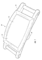
- the removable jewelry setting generally includes a lower body portion 12 pivotally connected to an upper body portion 22 and a latch assembly 28 for maintaining the assembly in a closed position while allowing access to the interior portion of the assembly when desired for attachment and removal of the jewelry setting.
- the lower body portion is provided with a channel 14 ( Figures 12 and 13 ) extending through, at least, the length of the lower body portion covered by the upper body portion 22.
- the channel preferably includes two spaced apart side walls 16, 18 defining the width of the channel 14, and a lower wall 20 spaced apart from the upper body portion 22 to define the height of the channel.
- the upper surface 32 of the lower body portion 12 includes a notch 33 to allow the upper body portion 22 to be recessed into the lower body portion 12.
- this construction provides lateral stability to the upper body portion in a closed and/or open position as illustrated in Figures 7 and 8 .
- the lower wall 20 is preferably integrally formed between the side walls 16, 18 to provide rigidity to the lower body portion.
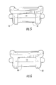
- the latch housing 34 is preferably formed as a tubular conduit positioned substantially transverse with respect to the channel 14 to contain a spring latch assembly 36.
- the spring latch assembly includes at least one spring member 40 and a sliding latch body 38 positioned to cooperate with a pawl member 42.
- the sliding latch body is preferably formed to include a shape that prevents rotation within the latch housing and includes a depression 52 therein that contains a catch 50. The catch is positioned within the depression for engagement with the pawl member 42.
- the pawl member is positioned on a lower surface 44 of the upper body portion 22 and preferably includes a first ramp surface 46 that is constructed and arranged to cooperate with a second ramp surface 48 on the catch 50 to cause movement of the sliding latch assembly 36 thereby compressing spring members 40. Upon passing the ramp surface, the compressed springs are released to cause the catch 50 to engage the pawl 42 to maintain the assembly in a closed position ( Figure 9 ).
- a manually engagable actuating portion illustrated herein as a button 54 that extends through a side wall of said lower body portion is provided for easy release of the latch assembly.
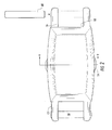
- the removable jewelry setting can be opened for insertion of an elongated member 56 into the channel and closed to lock the jewelry setting 10 to the elongated member. Removal merely requires the upper body portion to be released via the sliding latch assembly 36 to remove the jewelry setting for attachment to another elongated member. It should also be noted that in some embodiments the latch housing 34 extends a predetermined distance into the channel 14 to function as a pinch point (see Figures 12 and 13 ) between the lower wall 20 and the lower surface 44 of the upper body portion 22 to prevent the removable jewelry setting 10 from sliding along the elongated member 56 when positioned within the channel 14.
- the lower body portion 12 includes a length that is longer than the upper body portion 22 so that a portion of the lower body extends outward with respect to each end of the upper body portion.
- Each outward extending portion 58 of the lower body preferably includes a stabilizer member 60.
- Each stabilizer member is preferably arranged substantially perpendicular with respect to the channel, and each stabilizer member includes at least one surface constructed and arranged to cooperate with an elongated member 56 positioned in the channel to prevent rotation of the removable jewelry setting 10 about the elongated member.
- the stabilizer members 60 are positioned a sufficient distance outward with respect to said upper body portion to allow the elongated member 56 to be routed over or under each of the stabilizer members and through the channel for different appearances as shown in Figures 12 and 13 .
- the stabilizer members 60 may be removable and replaceable as illustrated in Figures 2 and 14 for different appearance or assembly to an elongated member.
- the upper body portion 22 preferably includes at least one mounting 24 on an upper surface 23 for a decorative, semi-precious or precious stone, or array of stones thereon that may include, but should not be limited to, cabochon stones or faceted stones. It should also be noted that the upper surface may include paints, plating or other surface coating(s) well known in the art for decorating jewelry and personal adornments.
- the upper surface mounting is selected from the group including, but not limited to, a claw setting, a bezel setting, a pave setting, a burnish setting, a prong setting, a v-prong setting, a channel setting, a tension setting, a bar setting, a carre setting, a bead setting, a rub over setting, an invisible setting or a semi mount.
- the upper body portion is preferably pivotally connected via a pin type hinge 26 ( Figures 9 and 10 ) to one of said side walls 16, 18 via pins 62 for movement between an open position and a closed position. It should be noted that the pin type hinge assembly 26 may be replaced with any number of hinges, well known in the art, without departing from the scope of the invention.
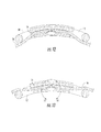
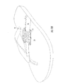
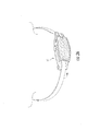
- FIG. 17 one embodiment of the removable jewelry setting secured to a pearl bracelet or necklace 70 is illustrated with the pearl string 72 extending over the stabilizers 60.
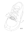
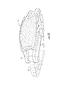
- FIG. 18 one embodiment of the removable jewelry setting secured to a sandal 74 is illustrated.
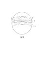
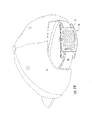
- FIG. 19 one embodiment of the removable jewelry setting secured to a hat 76 is illustrated.
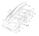
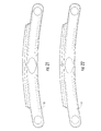
- FIG. 20-24 an alternative embodiment of the removable jewelry setting is illustrated. This embodiment includes converging sidewalls at each distal end of the jewelry setting.
- one embodiment of the removable jewelry setting is illustrated secured to an elongated member in the form of a bracelet, necklace, handbag strap or the like.
- the invention further includes the subject matter of the paragraphs of EP 10796519.6 from which this application is derived, the content of which is reproduced below as numbered paragraphs.
- a removable jewelry setting comprising:
- Paragraph 2 The removable jewelry setting of paragraph 1 wherein said latch assembly is manually releasable and includes a manually engagable actuating portion extending through a side wall of said lower body portion.
- Paragraph 3 The removable jewelry setting of paragraph 2 wherein said latch assembly is a sliding spring latch assembly, said spring latch assembly including a sliding latch body having a depression therein, a catch positioned within said depression for facilitating engagement with a pawl, a spring member connected to said latch body and said lower body portion for biasing said latch body to a latched position, said pawl positioned on a lower surface of said upper body portion.
- said spring latch assembly including a sliding latch body having a depression therein, a catch positioned within said depression for facilitating engagement with a pawl, a spring member connected to said latch body and said lower body portion for biasing said latch body to a latched position, said pawl positioned on a lower surface of said upper body portion.
- Paragraph 4 The removable jewelry setting of paragraph 3 wherein said lower body portion includes a tubular conduit for containing said spring latch assembly, said tubular conduit positioned substantially transverse with respect to said channel.
- Paragraph 5 The removable jewelry setting of paragraph 4 wherein said tubular conduit extends a predetermined distance into said channel to function as a pinch point between said lower body portion and said upper body portion to prevent said removable jewelry setting from sliding along said elongated member when positioned within said channel.
- Paragraph 6 The removable jewelry setting of paragraph 1 wherein said lower body includes a length that is longer than said upper body portion, a portion of said lower body extending outward with respect to each end of said upper body portion.
- each said outward extending portion of said lower body portion includes a stabilizer member, each said stabilizer member arranged substantially perpendicular with respect to said channel, each said stabilizer member including at least one surface constructed and arranged to cooperate with an elongated member positioned in said channel to prevent rotation of said removable jewelry setting about said elongated member.
- each said outward extending portion of said lower body portion includes a stabilizer member, each said stabilizer member arranged substantially perpendicular with respect to said channel, each said stabilizer member including at least one surface that is constructed and arranged to cooperate with an elongated object to which said removable jewelry setting is attached to prevent rotation of said removable jewelry.
- Paragraph 9 The removable jewelry setting of paragraph 6 wherein said stabilizer members are removable and replaceable.
- Paragraph 10 The removable jewelry setting of paragraph 6 wherein said elongated member may be routed over or under each said stabilizer member and through said channel for different appearances.
- Paragraph 11 The removable jewelry setting of paragraph 1 wherein said mounting is constructed and arranged to retain at least one cabochon stone.
- Paragraph 12 The removable jewelry setting of paragraph 1 wherein said mounting is constructed and arranged to retain at least one faceted stone.
- Paragraph 13 The removable jewelry setting of paragraph 12 wherein said mounting is selected from the group consisting of a claw setting, a bezel setting, a pave setting, a burnish setting, a prong setting, a v-prong setting, a channel setting, a tension setting, a bar setting, a carre setting, a bead setting, a rub over setting, an invisible setting or a semi mount.
- Paragraph 14 The removable jewelry setting of paragraph 1 wherein said lower body portion and said upper body portion include a curve extending between the distal ends thereof.
Landscapes
- Adornments (AREA)
Applications Claiming Priority (3)
| Application Number | Priority Date | Filing Date | Title |
|---|---|---|---|
| US79850310A | 2010-04-05 | 2010-04-05 | |
| US12/900,523 US8434327B2 (en) | 2010-04-05 | 2010-10-08 | Removable jewelry setting |
| EP10796519.6A EP2555646B1 (de) | 2010-04-05 | 2010-12-03 | Entfernbare schmuckfassung |
Related Parent Applications (2)
| Application Number | Title | Priority Date | Filing Date |
|---|---|---|---|
| EP10796519.6A Division EP2555646B1 (de) | 2010-04-05 | 2010-12-03 | Entfernbare schmuckfassung |
| EP10796519.6A Division-Into EP2555646B1 (de) | 2010-04-05 | 2010-12-03 | Entfernbare schmuckfassung |
Publications (3)
| Publication Number | Publication Date |
|---|---|
| EP2801277A2 true EP2801277A2 (de) | 2014-11-12 |
| EP2801277A3 EP2801277A3 (de) | 2015-04-08 |
| EP2801277B1 EP2801277B1 (de) | 2016-08-17 |
Family
ID=44708041
Family Applications (2)
| Application Number | Title | Priority Date | Filing Date |
|---|---|---|---|
| EP14160967.7A Active EP2801277B1 (de) | 2010-04-05 | 2010-12-03 | Entfernbare Schmuckfassung |
| EP10796519.6A Active EP2555646B1 (de) | 2010-04-05 | 2010-12-03 | Entfernbare schmuckfassung |
Family Applications After (1)
| Application Number | Title | Priority Date | Filing Date |
|---|---|---|---|
| EP10796519.6A Active EP2555646B1 (de) | 2010-04-05 | 2010-12-03 | Entfernbare schmuckfassung |
Country Status (8)
| Country | Link |
|---|---|
| US (1) | US8434327B2 (de) |
| EP (2) | EP2801277B1 (de) |
| JP (1) | JP5857033B2 (de) |
| CN (1) | CN102933113B (de) |
| CA (1) | CA2795490C (de) |
| DK (1) | DK2555646T3 (de) |
| ES (1) | ES2486717T3 (de) |
| WO (1) | WO2011126521A1 (de) |
Cited By (1)
| Publication number | Priority date | Publication date | Assignee | Title |
|---|---|---|---|---|
| USD968997S1 (en) | 2020-02-21 | 2022-11-08 | Venus by Maria Tash, Inc. | Earring |
Families Citing this family (5)
| Publication number | Priority date | Publication date | Assignee | Title |
|---|---|---|---|---|
| US9021835B2 (en) * | 2010-04-05 | 2015-05-05 | Babyak Holdings, LLC | Removable jewelry setting |
| DE102012017574A1 (de) * | 2012-09-06 | 2014-03-06 | Bettina Merz | Vorrichtung zum Anbringen von austauschbaren Gegenständen |
| WO2014163668A1 (en) * | 2013-04-03 | 2014-10-09 | Babyak Holdings, LLC | Removable jewelry setting |
| USD735068S1 (en) * | 2013-09-18 | 2015-07-28 | Arturo Garcia Pla | Bracelet |
| US8926169B1 (en) * | 2013-10-04 | 2015-01-06 | Aqua Master Ltd. | Timepiece case and timepiece incorporating the same |
Citations (11)
| Publication number | Priority date | Publication date | Assignee | Title |
|---|---|---|---|---|
| US899296A (en) | 1907-12-09 | 1908-09-22 | William Ritchie Elliot | Mounting for precious stones. |
| US1152340A (en) | 1915-01-23 | 1915-08-31 | O Z O Jewelry Mfg Company | Jewelry. |
| US2253343A (en) | 1940-06-25 | 1941-08-19 | Albert L Nalick | Multiple unit emblem |
| US2316225A (en) | 1941-04-22 | 1943-04-13 | Hoffmann Elisa Strajman De De | Ring-mounted jewelry |
| US2354513A (en) | 1942-11-16 | 1944-07-25 | Fitzer Mitchel | Interchangeable setting for finger rings |
| US2537445A (en) | 1948-12-10 | 1951-01-09 | Joseph E Couture | Abrasive dispenser for stonecutting saws |
| US3115758A (en) | 1961-02-07 | 1963-12-31 | Pre Met Manufactures Ltd | Finger ring with spring loaded mount for removable gems |
| US3509734A (en) | 1967-06-14 | 1970-05-05 | Henry B Lederer | Ornamental device with interchangeable magnetically biased member |
| US3605438A (en) | 1968-09-10 | 1971-09-20 | William Chalson & Co Inc | Bar pin with changeable non-rotatably secured ornament and intermediate member |
| US4393667A (en) | 1980-08-20 | 1983-07-19 | Martine Reinstein | Jewelry articles |
| US4794766A (en) | 1988-04-28 | 1989-01-03 | Schunk Shane P | Finger ring with interchangeable stone |
Family Cites Families (21)
| Publication number | Priority date | Publication date | Assignee | Title |
|---|---|---|---|---|
| US2271133A (en) | 1940-11-27 | 1942-01-27 | Thoresen Einal | Buckle and latch mechanism |
| GB1413090A (en) | 1973-11-16 | 1975-11-05 | Bannock E V | Jewellery |
| JPS55133378U (de) * | 1979-03-16 | 1980-09-20 | ||
| JPS59194819U (ja) * | 1983-06-10 | 1984-12-25 | 株式会社 博報堂 | 装飾用装身具 |
| DE8329307U1 (de) * | 1983-10-11 | 1984-03-15 | Itw-Ateco Gmbh, 2000 Norderstedt | Vorrichtung zum spannen von gurten oder dergleichen |
| FR2709574B1 (fr) * | 1993-09-03 | 1995-11-17 | Pequignet Montres | Montre-bracelet à bracelet interchangeable. |
| JP3010773U (ja) * | 1994-11-01 | 1995-05-09 | スー ウェン−トゥン | 腕時計の組成ユニット |
| CN1161186A (zh) * | 1995-11-21 | 1997-10-08 | 格兰德金有限公司 | 具有展开扣的扣紧物 |
| JP3034257U (ja) * | 1996-07-31 | 1997-02-14 | 株式会社遊企画 | 滑り止め具及び滑り止め具付装飾体 |
| JP2969263B2 (ja) * | 1997-03-18 | 1999-11-02 | 株式会社エル・ジェー・ビー | 装身具用錠型止め具 |
| IT242759Y1 (it) | 1997-07-31 | 2002-01-30 | Uno A Erre Italia Spa | Orologio da polso con cinturino agevolmente sostituibile e consostegno per il piazzamento su un piano d'appoggio |
| US6108276A (en) | 1998-10-21 | 2000-08-22 | Chen; Chien-Fang | Belt buckle with an attached watch |
| JP2004154383A (ja) * | 2002-11-07 | 2004-06-03 | Katsuo Iwama | バックル |
| US7249397B2 (en) | 2004-04-30 | 2007-07-31 | Norbert Abels | Hinged latch device with elongate strap hinge |
| EP1731052B1 (de) * | 2005-06-10 | 2012-11-21 | The Swatch Group Management Services AG | Hals- oder Armband mit regelmässig angeordneten Gliedern auf einem flexiblen Band |
| JP3124534U (ja) * | 2006-03-14 | 2006-08-24 | 澄代 金子 | 止め具付きレザーフラワーリボン |
| JP3123920U (ja) * | 2006-03-27 | 2006-08-03 | 株式会社商永商会 | 発光装身具 |
| JP3126798U (ja) * | 2006-08-28 | 2006-11-09 | 正明 白鳥 | ベルト用バックル |
| JP3129475U (ja) * | 2006-11-10 | 2007-02-22 | 株式会社ジュエリータクマ | 吊下げ式装身具 |
| JP2009060994A (ja) * | 2007-09-05 | 2009-03-26 | Casio Comput Co Ltd | バンド取付構造 |
| JP3165338U (ja) * | 2010-10-29 | 2011-01-13 | 株式会社エムアンドケイ・ヨコヤ | 帯留め |
-
2010
- 2010-10-08 US US12/900,523 patent/US8434327B2/en active Active
- 2010-12-03 ES ES10796519.6T patent/ES2486717T3/es active Active
- 2010-12-03 EP EP14160967.7A patent/EP2801277B1/de active Active
- 2010-12-03 DK DK10796519.6T patent/DK2555646T3/da active
- 2010-12-03 CN CN201080066428.6A patent/CN102933113B/zh active Active
- 2010-12-03 WO PCT/US2010/058821 patent/WO2011126521A1/en not_active Ceased
- 2010-12-03 EP EP10796519.6A patent/EP2555646B1/de active Active
- 2010-12-03 JP JP2013503732A patent/JP5857033B2/ja active Active
- 2010-12-03 CA CA2795490A patent/CA2795490C/en active Active
Patent Citations (11)
| Publication number | Priority date | Publication date | Assignee | Title |
|---|---|---|---|---|
| US899296A (en) | 1907-12-09 | 1908-09-22 | William Ritchie Elliot | Mounting for precious stones. |
| US1152340A (en) | 1915-01-23 | 1915-08-31 | O Z O Jewelry Mfg Company | Jewelry. |
| US2253343A (en) | 1940-06-25 | 1941-08-19 | Albert L Nalick | Multiple unit emblem |
| US2316225A (en) | 1941-04-22 | 1943-04-13 | Hoffmann Elisa Strajman De De | Ring-mounted jewelry |
| US2354513A (en) | 1942-11-16 | 1944-07-25 | Fitzer Mitchel | Interchangeable setting for finger rings |
| US2537445A (en) | 1948-12-10 | 1951-01-09 | Joseph E Couture | Abrasive dispenser for stonecutting saws |
| US3115758A (en) | 1961-02-07 | 1963-12-31 | Pre Met Manufactures Ltd | Finger ring with spring loaded mount for removable gems |
| US3509734A (en) | 1967-06-14 | 1970-05-05 | Henry B Lederer | Ornamental device with interchangeable magnetically biased member |
| US3605438A (en) | 1968-09-10 | 1971-09-20 | William Chalson & Co Inc | Bar pin with changeable non-rotatably secured ornament and intermediate member |
| US4393667A (en) | 1980-08-20 | 1983-07-19 | Martine Reinstein | Jewelry articles |
| US4794766A (en) | 1988-04-28 | 1989-01-03 | Schunk Shane P | Finger ring with interchangeable stone |
Cited By (3)
| Publication number | Priority date | Publication date | Assignee | Title |
|---|---|---|---|---|
| USD968997S1 (en) | 2020-02-21 | 2022-11-08 | Venus by Maria Tash, Inc. | Earring |
| USD972430S1 (en) | 2020-02-21 | 2022-12-13 | Venus by Maria Tash, Inc. | Earring |
| USD985414S1 (en) | 2020-02-21 | 2023-05-09 | Venus by Maria Tash, Inc. | Earring |
Also Published As
| Publication number | Publication date |
|---|---|
| CN102933113A (zh) | 2013-02-13 |
| US8434327B2 (en) | 2013-05-07 |
| HK1181621A1 (en) | 2013-11-15 |
| JP5857033B2 (ja) | 2016-02-10 |
| EP2555646A1 (de) | 2013-02-13 |
| CA2795490A1 (en) | 2011-10-13 |
| CA2795490C (en) | 2019-01-08 |
| ES2486717T3 (es) | 2014-08-19 |
| EP2801277B1 (de) | 2016-08-17 |
| HK1203784A1 (en) | 2015-11-06 |
| EP2555646B1 (de) | 2014-04-30 |
| JP2013523315A (ja) | 2013-06-17 |
| WO2011126521A1 (en) | 2011-10-13 |
| CN102933113B (zh) | 2015-09-16 |
| EP2801277A3 (de) | 2015-04-08 |
| US20110239704A1 (en) | 2011-10-06 |
| DK2555646T3 (da) | 2014-08-11 |
Similar Documents
| Publication | Publication Date | Title |
|---|---|---|
| US9021835B2 (en) | Removable jewelry setting | |
| US6729159B2 (en) | Interchangeable jewelry system | |
| US6804977B1 (en) | Necklace and bracelet pendant-clasp | |
| EP2801277B1 (de) | Entfernbare Schmuckfassung | |
| EP2627209B1 (de) | Dekorsystem mit befestigern und austauschbaren steckverbindern | |
| US5133195A (en) | Ornamental jewelry system | |
| US20080273162A1 (en) | Eyeglass hanging charm holder | |
| US20030074919A1 (en) | Decorative articles with interchangeable modules | |
| US20170224068A1 (en) | Item having a clasp apparatus to releasably set at least one interchangeable ornamental object | |
| US8973399B2 (en) | Latch mechanism for a timepiece | |
| US6209351B1 (en) | Interchangeable jewelry accessory | |
| US11109653B2 (en) | Jewelry ornament with clasp mechanism | |
| US20080006288A1 (en) | Combined hair clasp and necklace | |
| HK1203784B (en) | Removable jewelry setting | |
| TWI608807B (zh) | 可移除式珠寶底座 | |
| HK1181621B (en) | Removable jewelry setting | |
| US20140101894A1 (en) | Fastening device for jewelry | |
| JP4414318B2 (ja) | 装身具 | |
| US20100083703A1 (en) | Article of button jewelry | |
| KR200179934Y1 (ko) | 장신구 | |
| US20100163143A1 (en) | Bag with interchangeable ornamentation | |
| US20180027928A1 (en) | Footwear with customizable jewels and charms | |
| US20130318748A1 (en) | Fastening device to be worn on an arm | |
| CN108391913A (zh) | 一种方便组合的饰件 | |
| JP2005152495A (ja) | 着脱機構を有する装身具 |
Legal Events
| Date | Code | Title | Description |
|---|---|---|---|
| PUAI | Public reference made under article 153(3) epc to a published international application that has entered the european phase |
Free format text: ORIGINAL CODE: 0009012 |
|
| 17P | Request for examination filed |
Effective date: 20140320 |
|
| AC | Divisional application: reference to earlier application |
Ref document number: 2555646 Country of ref document: EP Kind code of ref document: P |
|
| AK | Designated contracting states |
Kind code of ref document: A2 Designated state(s): AL AT BE BG CH CY CZ DE DK EE ES FI FR GB GR HR HU IE IS IT LI LT LU LV MC MK MT NL NO PL PT RO RS SE SI SK SM TR |
|
| PUAL | Search report despatched |
Free format text: ORIGINAL CODE: 0009013 |
|
| AK | Designated contracting states |
Kind code of ref document: A3 Designated state(s): AL AT BE BG CH CY CZ DE DK EE ES FI FR GB GR HR HU IE IS IT LI LT LU LV MC MK MT NL NO PL PT RO RS SE SI SK SM TR |
|
| RIC1 | Information provided on ipc code assigned before grant |
Ipc: A44B 11/06 20060101ALI20150305BHEP Ipc: G04B 37/14 20060101ALI20150305BHEP Ipc: A44C 17/02 20060101AFI20150305BHEP |
|
| RAP1 | Party data changed (applicant data changed or rights of an application transferred) |
Owner name: BABYAK HOLDINGS, LLC |
|
| REG | Reference to a national code |
Ref country code: HK Ref legal event code: DE Ref document number: 1203784 Country of ref document: HK |
|
| R17P | Request for examination filed (corrected) |
Effective date: 20151007 |
|
| RBV | Designated contracting states (corrected) |
Designated state(s): AL AT BE BG CH CY CZ DE DK EE ES FI FR GB GR HR HU IE IS IT LI LT LU LV MC MK MT NL NO PL PT RO RS SE SI SK SM TR |
|
| GRAP | Despatch of communication of intention to grant a patent |
Free format text: ORIGINAL CODE: EPIDOSNIGR1 |
|
| INTG | Intention to grant announced |
Effective date: 20160225 |
|
| GRAS | Grant fee paid |
Free format text: ORIGINAL CODE: EPIDOSNIGR3 |
|
| GRAA | (expected) grant |
Free format text: ORIGINAL CODE: 0009210 |
|
| AC | Divisional application: reference to earlier application |
Ref document number: 2555646 Country of ref document: EP Kind code of ref document: P |
|
| AK | Designated contracting states |
Kind code of ref document: B1 Designated state(s): AL AT BE BG CH CY CZ DE DK EE ES FI FR GB GR HR HU IE IS IT LI LT LU LV MC MK MT NL NO PL PT RO RS SE SI SK SM TR |
|
| REG | Reference to a national code |
Ref country code: GB Ref legal event code: FG4D |
|
| REG | Reference to a national code |
Ref country code: CH Ref legal event code: EP |
|
| REG | Reference to a national code |
Ref country code: IE Ref legal event code: FG4D |
|
| REG | Reference to a national code |
Ref country code: AT Ref legal event code: REF Ref document number: 820190 Country of ref document: AT Kind code of ref document: T Effective date: 20160915 |
|
| REG | Reference to a national code |
Ref country code: DE Ref legal event code: R096 Ref document number: 602010035731 Country of ref document: DE |
|
| REG | Reference to a national code |
Ref country code: NL Ref legal event code: MP Effective date: 20160817 |
|
| REG | Reference to a national code |
Ref country code: LT Ref legal event code: MG4D |
|
| REG | Reference to a national code |
Ref country code: CH Ref legal event code: NV Representative=s name: MICHELI AND CIE SA, CH |
|
| REG | Reference to a national code |
Ref country code: AT Ref legal event code: MK05 Ref document number: 820190 Country of ref document: AT Kind code of ref document: T Effective date: 20160817 |
|
| PG25 | Lapsed in a contracting state [announced via postgrant information from national office to epo] |
Ref country code: LT Free format text: LAPSE BECAUSE OF FAILURE TO SUBMIT A TRANSLATION OF THE DESCRIPTION OR TO PAY THE FEE WITHIN THE PRESCRIBED TIME-LIMIT Effective date: 20160817 Ref country code: IT Free format text: LAPSE BECAUSE OF FAILURE TO SUBMIT A TRANSLATION OF THE DESCRIPTION OR TO PAY THE FEE WITHIN THE PRESCRIBED TIME-LIMIT Effective date: 20160817 Ref country code: RS Free format text: LAPSE BECAUSE OF FAILURE TO SUBMIT A TRANSLATION OF THE DESCRIPTION OR TO PAY THE FEE WITHIN THE PRESCRIBED TIME-LIMIT Effective date: 20160817 Ref country code: FI Free format text: LAPSE BECAUSE OF FAILURE TO SUBMIT A TRANSLATION OF THE DESCRIPTION OR TO PAY THE FEE WITHIN THE PRESCRIBED TIME-LIMIT Effective date: 20160817 Ref country code: NO Free format text: LAPSE BECAUSE OF FAILURE TO SUBMIT A TRANSLATION OF THE DESCRIPTION OR TO PAY THE FEE WITHIN THE PRESCRIBED TIME-LIMIT Effective date: 20161117 Ref country code: NL Free format text: LAPSE BECAUSE OF FAILURE TO SUBMIT A TRANSLATION OF THE DESCRIPTION OR TO PAY THE FEE WITHIN THE PRESCRIBED TIME-LIMIT Effective date: 20160817 Ref country code: HR Free format text: LAPSE BECAUSE OF FAILURE TO SUBMIT A TRANSLATION OF THE DESCRIPTION OR TO PAY THE FEE WITHIN THE PRESCRIBED TIME-LIMIT Effective date: 20160817 |
|
| PG25 | Lapsed in a contracting state [announced via postgrant information from national office to epo] |
Ref country code: PT Free format text: LAPSE BECAUSE OF FAILURE TO SUBMIT A TRANSLATION OF THE DESCRIPTION OR TO PAY THE FEE WITHIN THE PRESCRIBED TIME-LIMIT Effective date: 20161219 Ref country code: ES Free format text: LAPSE BECAUSE OF FAILURE TO SUBMIT A TRANSLATION OF THE DESCRIPTION OR TO PAY THE FEE WITHIN THE PRESCRIBED TIME-LIMIT Effective date: 20160817 Ref country code: SE Free format text: LAPSE BECAUSE OF FAILURE TO SUBMIT A TRANSLATION OF THE DESCRIPTION OR TO PAY THE FEE WITHIN THE PRESCRIBED TIME-LIMIT Effective date: 20160817 Ref country code: LV Free format text: LAPSE BECAUSE OF FAILURE TO SUBMIT A TRANSLATION OF THE DESCRIPTION OR TO PAY THE FEE WITHIN THE PRESCRIBED TIME-LIMIT Effective date: 20160817 Ref country code: PL Free format text: LAPSE BECAUSE OF FAILURE TO SUBMIT A TRANSLATION OF THE DESCRIPTION OR TO PAY THE FEE WITHIN THE PRESCRIBED TIME-LIMIT Effective date: 20160817 Ref country code: GR Free format text: LAPSE BECAUSE OF FAILURE TO SUBMIT A TRANSLATION OF THE DESCRIPTION OR TO PAY THE FEE WITHIN THE PRESCRIBED TIME-LIMIT Effective date: 20161118 Ref country code: AT Free format text: LAPSE BECAUSE OF FAILURE TO SUBMIT A TRANSLATION OF THE DESCRIPTION OR TO PAY THE FEE WITHIN THE PRESCRIBED TIME-LIMIT Effective date: 20160817 |
|
| REG | Reference to a national code |
Ref country code: FR Ref legal event code: PLFP Year of fee payment: 7 |
|
| PG25 | Lapsed in a contracting state [announced via postgrant information from national office to epo] |
Ref country code: RO Free format text: LAPSE BECAUSE OF FAILURE TO SUBMIT A TRANSLATION OF THE DESCRIPTION OR TO PAY THE FEE WITHIN THE PRESCRIBED TIME-LIMIT Effective date: 20160817 Ref country code: EE Free format text: LAPSE BECAUSE OF FAILURE TO SUBMIT A TRANSLATION OF THE DESCRIPTION OR TO PAY THE FEE WITHIN THE PRESCRIBED TIME-LIMIT Effective date: 20160817 |
|
| REG | Reference to a national code |
Ref country code: DE Ref legal event code: R097 Ref document number: 602010035731 Country of ref document: DE |
|
| PG25 | Lapsed in a contracting state [announced via postgrant information from national office to epo] |
Ref country code: BE Free format text: LAPSE BECAUSE OF FAILURE TO SUBMIT A TRANSLATION OF THE DESCRIPTION OR TO PAY THE FEE WITHIN THE PRESCRIBED TIME-LIMIT Effective date: 20160817 Ref country code: SM Free format text: LAPSE BECAUSE OF FAILURE TO SUBMIT A TRANSLATION OF THE DESCRIPTION OR TO PAY THE FEE WITHIN THE PRESCRIBED TIME-LIMIT Effective date: 20160817 Ref country code: CZ Free format text: LAPSE BECAUSE OF FAILURE TO SUBMIT A TRANSLATION OF THE DESCRIPTION OR TO PAY THE FEE WITHIN THE PRESCRIBED TIME-LIMIT Effective date: 20160817 Ref country code: BG Free format text: LAPSE BECAUSE OF FAILURE TO SUBMIT A TRANSLATION OF THE DESCRIPTION OR TO PAY THE FEE WITHIN THE PRESCRIBED TIME-LIMIT Effective date: 20161117 Ref country code: DK Free format text: LAPSE BECAUSE OF FAILURE TO SUBMIT A TRANSLATION OF THE DESCRIPTION OR TO PAY THE FEE WITHIN THE PRESCRIBED TIME-LIMIT Effective date: 20160817 Ref country code: SK Free format text: LAPSE BECAUSE OF FAILURE TO SUBMIT A TRANSLATION OF THE DESCRIPTION OR TO PAY THE FEE WITHIN THE PRESCRIBED TIME-LIMIT Effective date: 20160817 |
|
| PLBE | No opposition filed within time limit |
Free format text: ORIGINAL CODE: 0009261 |
|
| STAA | Information on the status of an ep patent application or granted ep patent |
Free format text: STATUS: NO OPPOSITION FILED WITHIN TIME LIMIT |
|
| 26N | No opposition filed |
Effective date: 20170518 |
|
| PG25 | Lapsed in a contracting state [announced via postgrant information from national office to epo] |
Ref country code: SI Free format text: LAPSE BECAUSE OF FAILURE TO SUBMIT A TRANSLATION OF THE DESCRIPTION OR TO PAY THE FEE WITHIN THE PRESCRIBED TIME-LIMIT Effective date: 20160817 |
|
| PG25 | Lapsed in a contracting state [announced via postgrant information from national office to epo] |
Ref country code: MC Free format text: LAPSE BECAUSE OF FAILURE TO SUBMIT A TRANSLATION OF THE DESCRIPTION OR TO PAY THE FEE WITHIN THE PRESCRIBED TIME-LIMIT Effective date: 20160817 |
|
| PG25 | Lapsed in a contracting state [announced via postgrant information from national office to epo] |
Ref country code: LU Free format text: LAPSE BECAUSE OF NON-PAYMENT OF DUE FEES Effective date: 20161203 |
|
| REG | Reference to a national code |
Ref country code: HK Ref legal event code: GR Ref document number: 1203784 Country of ref document: HK |
|
| REG | Reference to a national code |
Ref country code: FR Ref legal event code: PLFP Year of fee payment: 8 |
|
| PG25 | Lapsed in a contracting state [announced via postgrant information from national office to epo] |
Ref country code: HU Free format text: LAPSE BECAUSE OF FAILURE TO SUBMIT A TRANSLATION OF THE DESCRIPTION OR TO PAY THE FEE WITHIN THE PRESCRIBED TIME-LIMIT; INVALID AB INITIO Effective date: 20101203 |
|
| PG25 | Lapsed in a contracting state [announced via postgrant information from national office to epo] |
Ref country code: MK Free format text: LAPSE BECAUSE OF FAILURE TO SUBMIT A TRANSLATION OF THE DESCRIPTION OR TO PAY THE FEE WITHIN THE PRESCRIBED TIME-LIMIT Effective date: 20160817 Ref country code: IS Free format text: LAPSE BECAUSE OF FAILURE TO SUBMIT A TRANSLATION OF THE DESCRIPTION OR TO PAY THE FEE WITHIN THE PRESCRIBED TIME-LIMIT Effective date: 20160817 Ref country code: CY Free format text: LAPSE BECAUSE OF FAILURE TO SUBMIT A TRANSLATION OF THE DESCRIPTION OR TO PAY THE FEE WITHIN THE PRESCRIBED TIME-LIMIT Effective date: 20160817 |
|
| PG25 | Lapsed in a contracting state [announced via postgrant information from national office to epo] |
Ref country code: MT Free format text: LAPSE BECAUSE OF NON-PAYMENT OF DUE FEES Effective date: 20161203 |
|
| PG25 | Lapsed in a contracting state [announced via postgrant information from national office to epo] |
Ref country code: TR Free format text: LAPSE BECAUSE OF FAILURE TO SUBMIT A TRANSLATION OF THE DESCRIPTION OR TO PAY THE FEE WITHIN THE PRESCRIBED TIME-LIMIT Effective date: 20160817 Ref country code: AL Free format text: LAPSE BECAUSE OF FAILURE TO SUBMIT A TRANSLATION OF THE DESCRIPTION OR TO PAY THE FEE WITHIN THE PRESCRIBED TIME-LIMIT Effective date: 20160817 |
|
| REG | Reference to a national code |
Ref country code: CH Ref legal event code: U11 Free format text: ST27 STATUS EVENT CODE: U-0-0-U10-U11 (AS PROVIDED BY THE NATIONAL OFFICE) Effective date: 20260106 |
|
| PGFP | Annual fee paid to national office [announced via postgrant information from national office to epo] |
Ref country code: DE Payment date: 20251203 Year of fee payment: 16 |
|
| PGFP | Annual fee paid to national office [announced via postgrant information from national office to epo] |
Ref country code: GB Payment date: 20251118 Year of fee payment: 16 |
|
| PGFP | Annual fee paid to national office [announced via postgrant information from national office to epo] |
Ref country code: FR Payment date: 20251205 Year of fee payment: 16 |
|
| PGFP | Annual fee paid to national office [announced via postgrant information from national office to epo] |
Ref country code: IE Payment date: 20251217 Year of fee payment: 16 |
|
| PGFP | Annual fee paid to national office [announced via postgrant information from national office to epo] |
Ref country code: CH Payment date: 20260106 Year of fee payment: 16 |