EP2801409B1 - Conduite de liquide dotée d'un corps de tuyère associé - Google Patents
Conduite de liquide dotée d'un corps de tuyère associé Download PDFInfo
- Publication number
- EP2801409B1 EP2801409B1 EP14401050.1A EP14401050A EP2801409B1 EP 2801409 B1 EP2801409 B1 EP 2801409B1 EP 14401050 A EP14401050 A EP 14401050A EP 2801409 B1 EP2801409 B1 EP 2801409B1
- Authority
- EP
- European Patent Office
- Prior art keywords
- liquid
- line
- nozzle body
- shut
- liquid line
- Prior art date
- Legal status (The legal status is an assumption and is not a legal conclusion. Google has not performed a legal analysis and makes no representation as to the accuracy of the status listed.)
- Active
Links
Images


Classifications
-
- B—PERFORMING OPERATIONS; TRANSPORTING
- B05—SPRAYING OR ATOMISING IN GENERAL; APPLYING FLUENT MATERIALS TO SURFACES, IN GENERAL
- B05B—SPRAYING APPARATUS; ATOMISING APPARATUS; NOZZLES
- B05B1/00—Nozzles, spray heads or other outlets, with or without auxiliary devices such as valves, heating means
- B05B1/14—Nozzles, spray heads or other outlets, with or without auxiliary devices such as valves, heating means with multiple outlet openings; with strainers in or outside the outlet opening
- B05B1/16—Nozzles, spray heads or other outlets, with or without auxiliary devices such as valves, heating means with multiple outlet openings; with strainers in or outside the outlet opening having selectively- effective outlets
- B05B1/1609—Nozzles, spray heads or other outlets, with or without auxiliary devices such as valves, heating means with multiple outlet openings; with strainers in or outside the outlet opening having selectively- effective outlets with a selecting mechanism comprising a lift valve
-
- B—PERFORMING OPERATIONS; TRANSPORTING
- B05—SPRAYING OR ATOMISING IN GENERAL; APPLYING FLUENT MATERIALS TO SURFACES, IN GENERAL
- B05B—SPRAYING APPARATUS; ATOMISING APPARATUS; NOZZLES
- B05B1/00—Nozzles, spray heads or other outlets, with or without auxiliary devices such as valves, heating means
- B05B1/14—Nozzles, spray heads or other outlets, with or without auxiliary devices such as valves, heating means with multiple outlet openings; with strainers in or outside the outlet opening
- B05B1/16—Nozzles, spray heads or other outlets, with or without auxiliary devices such as valves, heating means with multiple outlet openings; with strainers in or outside the outlet opening having selectively- effective outlets
- B05B1/169—Nozzles, spray heads or other outlets, with or without auxiliary devices such as valves, heating means with multiple outlet openings; with strainers in or outside the outlet opening having selectively- effective outlets having three or more selectively effective outlets
-
- B—PERFORMING OPERATIONS; TRANSPORTING
- B05—SPRAYING OR ATOMISING IN GENERAL; APPLYING FLUENT MATERIALS TO SURFACES, IN GENERAL
- B05B—SPRAYING APPARATUS; ATOMISING APPARATUS; NOZZLES
- B05B1/00—Nozzles, spray heads or other outlets, with or without auxiliary devices such as valves, heating means
- B05B1/14—Nozzles, spray heads or other outlets, with or without auxiliary devices such as valves, heating means with multiple outlet openings; with strainers in or outside the outlet opening
- B05B1/20—Perforated pipes or troughs, e.g. spray booms; Outlet elements therefor
-
- B—PERFORMING OPERATIONS; TRANSPORTING
- B05—SPRAYING OR ATOMISING IN GENERAL; APPLYING FLUENT MATERIALS TO SURFACES, IN GENERAL
- B05B—SPRAYING APPARATUS; ATOMISING APPARATUS; NOZZLES
- B05B1/00—Nozzles, spray heads or other outlets, with or without auxiliary devices such as valves, heating means
- B05B1/30—Nozzles, spray heads or other outlets, with or without auxiliary devices such as valves, heating means designed to control volume of flow, e.g. with adjustable passages
- B05B1/3013—Lift valves
- B05B1/302—Lift valves with a ball shaped valve member
-
- B—PERFORMING OPERATIONS; TRANSPORTING
- B05—SPRAYING OR ATOMISING IN GENERAL; APPLYING FLUENT MATERIALS TO SURFACES, IN GENERAL
- B05B—SPRAYING APPARATUS; ATOMISING APPARATUS; NOZZLES
- B05B15/00—Details of spraying plant or spraying apparatus not otherwise provided for; Accessories
- B05B15/50—Arrangements for cleaning; Arrangements for preventing deposits, drying-out or blockage; Arrangements for detecting improper discharge caused by the presence of foreign matter
-
- F—MECHANICAL ENGINEERING; LIGHTING; HEATING; WEAPONS; BLASTING
- F16—ENGINEERING ELEMENTS AND UNITS; GENERAL MEASURES FOR PRODUCING AND MAINTAINING EFFECTIVE FUNCTIONING OF MACHINES OR INSTALLATIONS; THERMAL INSULATION IN GENERAL
- F16K—VALVES; TAPS; COCKS; ACTUATING-FLOATS; DEVICES FOR VENTING OR AERATING
- F16K11/00—Multiple-way valves, e.g. mixing valves; Pipe fittings incorporating such valves
- F16K11/10—Multiple-way valves, e.g. mixing valves; Pipe fittings incorporating such valves with two or more closure members not moving as a unit
- F16K11/14—Multiple-way valves, e.g. mixing valves; Pipe fittings incorporating such valves with two or more closure members not moving as a unit operated by one actuating member, e.g. a handle
- F16K11/16—Multiple-way valves, e.g. mixing valves; Pipe fittings incorporating such valves with two or more closure members not moving as a unit operated by one actuating member, e.g. a handle which only slides, or only turns, or only swings in one plane
- F16K11/163—Multiple-way valves, e.g. mixing valves; Pipe fittings incorporating such valves with two or more closure members not moving as a unit operated by one actuating member, e.g. a handle which only slides, or only turns, or only swings in one plane only turns
- F16K11/166—Multiple-way valves, e.g. mixing valves; Pipe fittings incorporating such valves with two or more closure members not moving as a unit operated by one actuating member, e.g. a handle which only slides, or only turns, or only swings in one plane only turns with the rotating spindles at right angles to the closure members
-
- F—MECHANICAL ENGINEERING; LIGHTING; HEATING; WEAPONS; BLASTING
- F16—ENGINEERING ELEMENTS AND UNITS; GENERAL MEASURES FOR PRODUCING AND MAINTAINING EFFECTIVE FUNCTIONING OF MACHINES OR INSTALLATIONS; THERMAL INSULATION IN GENERAL
- F16K—VALVES; TAPS; COCKS; ACTUATING-FLOATS; DEVICES FOR VENTING OR AERATING
- F16K31/00—Actuating devices; Operating means; Releasing devices
- F16K31/44—Mechanical actuating means
- F16K31/52—Mechanical actuating means with crank, eccentric, or cam
- F16K31/524—Mechanical actuating means with crank, eccentric, or cam with a cam
- F16K31/52408—Mechanical actuating means with crank, eccentric, or cam with a cam comprising a lift valve
- F16K31/52416—Mechanical actuating means with crank, eccentric, or cam with a cam comprising a lift valve comprising a multiple-way lift valve
-
- F—MECHANICAL ENGINEERING; LIGHTING; HEATING; WEAPONS; BLASTING
- F16—ENGINEERING ELEMENTS AND UNITS; GENERAL MEASURES FOR PRODUCING AND MAINTAINING EFFECTIVE FUNCTIONING OF MACHINES OR INSTALLATIONS; THERMAL INSULATION IN GENERAL
- F16K—VALVES; TAPS; COCKS; ACTUATING-FLOATS; DEVICES FOR VENTING OR AERATING
- F16K31/00—Actuating devices; Operating means; Releasing devices
- F16K31/44—Mechanical actuating means
- F16K31/52—Mechanical actuating means with crank, eccentric, or cam
- F16K31/524—Mechanical actuating means with crank, eccentric, or cam with a cam
- F16K31/52408—Mechanical actuating means with crank, eccentric, or cam with a cam comprising a lift valve
- F16K31/52425—Mechanical actuating means with crank, eccentric, or cam with a cam comprising a lift valve with a ball-shaped valve member
Definitions
- the invention relates to a liquid line with an associated nozzle body according to the preamble of patent claim 1.
- Such a liquid line with an associated nozzle body is in the DE 10 2010 036 437 A1 described.
- a branch line branches off from the liquid line in a branch area to the at least one discharge nozzle of the nozzle body.
- the branch line is assigned at least one shut-off valve.
- a portion of the liquid flow branches off to the dispensing nozzle.
- the shut-off element is essentially only washed around if the shut-off element releases the flow in the branch line to the dispensing nozzle.
- particles present in the liquid, such as pesticide solutions are deposited. The deposition of the particles, in particular in the shut-off area of the shut-off elements, leads to changes in the application rate and to problems when the branch line is shut off by the shut-off elements.
- the object of the invention is to avoid, in a simple manner, at least when the branch line is shut off by the shut-off elements, an obstructive deposition of particles present in the liquid to be dispensed, such as, for example, crop protection agent solutions.
- shut-off elements lie in a region of the liquid flow and are flowed around and / or washed around by a liquid flow which is larger than the quantity of liquid applied via the dispensing nozzle.
- the flow of the liquid flow in the area of the shut-off elements is increased to such an extent that there is always one in all applications there is sufficient flow of the liquid flow in the shut-off area so that no particles from the liquid flow can deposit in a manner which impedes the functioning of the shut-off element.
- the shut-off elements can even protrude into the main liquid flow of the liquid line.
- At least one intermediate wall protruding into the free cross section of the liquid line and having at least one front separating edge is arranged in the branch area, between the at least one separating edge and the line wall of the liquid line is at least one opening leading to the at least one branch line, that at least one further opening connecting the branch line to the liquid line is arranged on the end of the intermediate wall facing away from the end separating edge.
- the liquid flow is arranged in the branch line.
- a gap area through which the liquid flow can flow is arranged between the two side surfaces of the actuating disc and the respectively adjacent housing walls is that the openings on the end face and the end of the intermediate wall are connected to one another by the gap region between the two side surfaces of the actuating disk and the respectively adjacent housing walls. This ensures that no particles from the liquid flow can deposit in the gap area either.
- the liquid flow can be conducted to the at least one dispensing nozzle arranged on the nozzle body through the at least one guide wall guiding the liquid flow.
- the guide wall is designed as a bead which, on the side of the intermediate wall facing away from the branch line, preferably extends in a curve-like manner in the direction of the dispensing nozzle.
- the liquid flow is divided by the bead and directed to the respective dispensing nozzle.
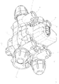
- the multiple nozzle body according to the 1 to 10 has the housing 1.
- the fastening means 2, with which the multiple nozzle body can be fastened to frame elements, distributor rods, etc., is arranged on the housing.
- the liquid to be dispensed is to be fed to the respective multiple nozzle body via this liquid line, which is arranged, for example, on a distributor linkage of an agricultural field sprayer.
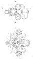
- the liquid line 3 is connected to the branch line 5 arranged in the housing 1 in a branch region 4.
- the branch line 5 opens into the distributor space 6 arranged in the housing 1. From this distribution room 6 lead, according to the embodiment, four connecting lines 7, which form the extension of the branch line 5, to discharge lines 8 arranged in the housing 1, at the ends 9 of which discharge nozzles are arranged in a manner not shown by means of union nuts in a known manner.
- the connecting lines 7 are to be shut off in the area of the distributor space 6 by means of shut-off valves 11 having shut-off elements 10. Via these shut-off elements 10, the connecting lines 7 can optionally be connected to the feed line 5 and / or shut off from them.
- the shut-off elements 10 can be actuated via switchable actuating elements 12 and can thus be brought into the respective shut-off or flow position.
- the shut-off valves 11 each have a valve seat 13 arranged in the housing 1, to which a sealing ring 14 is assigned.
- the shut-off elements 10 are spherical, designed as spheres in the exemplary embodiment. If the balls 10 are in the valve seat 13, they cooperate with the sealing ring 14 of the valve seat 13 in this shut-off position.
- the balls 10 are assigned compression springs 15, by means of which they are pressed in the direction of the valve seat 13.
- the switchable actuating element 12 is disc-shaped and non-rotatably connected to a switching shaft 16 mounted in the housing 1.
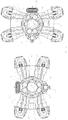
- the actuating element 12 has a plurality of switching cams 17, 18, such as the 9 and 10 point to. According to the exemplary embodiment, the actuating element 12 has two switching cams 17, 18.
- the control shaft 16 of the actuating element 12 is connected in a rotationally fixed manner to a motorized actuating element 19, which is designed as an electric motor, and can thus be rotated about its axis of rotation by the motorized actuating element.
- One of the two switching cams 17 is designed such that it can only press a valve element designed as a ball 10 out of the valve seat 13, so that the flow to a connecting line 7 is released.
- the other of the two switching cams 18 is designed in such a way that it simultaneously shuts off two shut-off elements which are arranged as balls 10 and which flow into one another can move respective connecting lines 7 releasing position, that is, he can simultaneously press two valve elements designed as balls 10 out of their valve seats 13.
- the actuating element 11 with the two switching cams 19, 20 can be rotated into different positions, as is the case for some possible positions in the 9 and 10 is shown. As can be seen from this, depending on the switching position of the actuating element 12, the flow for none, one or more connecting lines 7 leading to the application nozzles application lines 8 are released. Thus, optionally, none, one or more connecting lines 7 and thus dispensing nozzles can be supplied in different combinations to the liquid to be dispensed.
- an intermediate wall 22 which projects into the free cross section of the liquid line 3 and has the end separating edge 21. Between the separating edge 21 and the line wall 23 of the liquid line 3 there is an opening 24 leading to the branch line 5. Furthermore, an additional opening 26 connecting the branch line 26 to the liquid line 3 is arranged on the end 25 of the intermediate wall 22 facing away from the end separating edge 21 . The opening 27 at the end separating edge 21 of the intermediate wall 22 is in flow connection with the further opening 24 at the end 25 of the intermediate wall 22.
- a further intermediate line 28, which is connected to the liquid line 3 and has an opening 24 to the liquid line 3, is thus assigned from the branch line 5 in the area of the shut-off elements 10.
- a guide wall 29 Arranged in the branch line 5 is a guide wall 29 which begins at the front separating edge 21 and leads to the respective flow nozzle of the nozzle body and guides the liquid flow.
- the guide wall 29 is designed as a bead 30 running on the side of the intermediate wall 22 facing away from the branch line 5 and extending in a curve in the direction of the dispensing nozzle.
- a gap region 32 through which the liquid flow can flow is arranged between the two side surfaces of the actuating disc 12 and the respectively adjacent housing walls.
- the openings 24 and 28 on the end face and the end of the intermediate wall 22 are connected to one another by the gap region 32 between the two side surfaces of the actuating disk 12 and the respectively adjacent housing walls.
- the liquid flow is fed to the dispensing nozzle arranged on the nozzle body.
- shut-off elements 10 Due to the arrangement of the shut-off elements 10 described above, they lie in the area of the liquid flow and are flowed around and / or washed around by a liquid flow which is greater than the quantity of liquid applied via the dispensing nozzle.
- the multiple nozzle body according to Fig. 11 differs in another embodiment of the arrangement of the intermediate wall 33 and the branch line 34 from the liquid line 3 and the additional connecting line 35 from the branch line 34 to the liquid line 3.
- the arrangement of the shut-off elements 10 via the actuating sheath 12 corresponds to the previous exemplary embodiment.
- the multiple nozzle body according to Fig. 12 differs by a different arrangement and position of the shut-off elements 10.
- the shut-off elements 10 are located directly within the liquid line 3 and here the liquid stream flows directly around and around them.
- the shut-off elements 10 are thus arranged in a region of the liquid flow which is larger than the amount of liquid applied via the dispensing nozzle.
- the shut-off elements 10 are actuated via the actuating disk 12, as described for the first exemplary embodiment.
Landscapes
- Engineering & Computer Science (AREA)
- General Engineering & Computer Science (AREA)
- Mechanical Engineering (AREA)
- Nozzles (AREA)
Claims (7)
- Conduite de liquide (3) comprenant un corps de buse associé, une conduite de dérivation (5, 34) conduisant vers l'au moins une buse de décharge du corps de buse étant déviée dans une région de dérivation (4) à partir de la conduite de liquide (3) présentant au moins une paroi de conduite, une soupape d'arrêt (11) présentant des éléments d'arrêt (10) étant associée à la conduite de dérivation (5), une quantité partielle du flux de liquide (3) dans la conduite de liquide étant déviée dans la conduite de dérivation (5, 34) vers la buse de décharge, caractérisée en ce que les éléments d'arrêt (10) sont situés dans une région du flux de liquide et sont enveloppés ou entourés par un flux de liquide qui est plus important que la quantité de liquide évacuée par le biais de la buse de décharge, en ce que depuis la conduite de dérivation (5, 34) dans la région des éléments d'arrêt (10) est associée une conduite intermédiaire supplémentaire (28, 35) connectée à la conduite de liquide (3) et présentant une ouverture pour la conduite de liquide (3).
- Conduite de liquide selon la revendication 1, caractérisée en ce qu'au moins une paroi intermédiaire (22) pénétrant dans la section transversale libre de la conduite de liquide (3) et présentant au moins une arête de séparation frontale (21) est disposée dans la région de dérivation (4), en ce qu'entre l'au moins une arête de séparation (21) et la paroi de conduite (23) de la conduite de liquide (3) se trouve au moins une ouverture conduisant à l'au moins une conduite de dérivation (5), en ce qu'au moins une ouverture supplémentaire (26) reliant la conduite de dérivation (5) à la conduite de liquide (3) est disposée à l'extrémité (25) de la paroi intermédiaire (22) opposée à l'arête de séparation frontale (21).
- Conduite de liquide selon la revendication 2, caractérisée en ce qu'au moins une paroi de guidage (29) commençant au niveau de l'arête de séparation frontale (21) et conduisant le flux de liquide jusqu'à la buse de décharge respective du corps de buse est disposée dans la conduite de dérivation (5).
- Conduite de liquide selon au moins l'une des revendications 2 et/ou 3, caractérisée en ce qu'au moins une ouverture (27) au niveau de l'arête de séparation frontale (21) de la paroi intermédiaire (22) est en liaison d'écoulement de passage avec au moins une ouverture supplémentaire (24) à l'extrémité (25) de la paroi intermédiaire (22).
- Conduite de liquide selon au moins l'une des revendications 2 à 4, dans laquelle le corps de buse est réalisé sous forme de corps à buses multiples et présente des soupapes d'arrêt pouvant être actionnées par le biais de cames de commutation disposées au niveau d'un disque d'actionnement et associées aux buses de décharge disposées au niveau du boîtier du corps à buses multiples, caractérisée en ce qu'entre les deux surfaces latérales du disque d'actionnement (12) et les parois de boîtier respectivement adjacentes est disposée une région de fente (31) pouvant être parcourue par l'écoulement du flux de liquide, en ce que les ouvertures sont connectées l'une à l'autre au niveau du côté frontal et à l'extrémité de la paroi intermédiaire (22) entre la région de fente (31) entre les deux surfaces latérales du disque d'actionnement (12) et les parois de boîtier respectivement adjacentes.
- Conduite de liquide selon la revendication 3, caractérisée en ce que le flux de liquide peut être conduit jusqu'à l'au moins une buse de décharge disposée au niveau du corps de buse à travers l'au moins une paroi de guidage (29) guidant le fluide liquide.
- Conduite de liquide selon la revendication 3 ou 6, caractérisée en ce que la paroi de guidage (29) est réalisée sous forme de bourrelet (30) s'étendant dans la direction de la buse de décharge de préférence sous forme courbe du côté de la paroi intermédiaire (22) opposé à la conduite de dérivation (5, 34).
Applications Claiming Priority (1)
| Application Number | Priority Date | Filing Date | Title |
|---|---|---|---|
| DE102013104670.3A DE102013104670A1 (de) | 2013-05-07 | 2013-05-07 | Flüssigkeitsleitung mit zugeordnetem Düsenkörper |
Publications (2)
| Publication Number | Publication Date |
|---|---|
| EP2801409A1 EP2801409A1 (fr) | 2014-11-12 |
| EP2801409B1 true EP2801409B1 (fr) | 2020-04-08 |
Family
ID=50884843
Family Applications (1)
| Application Number | Title | Priority Date | Filing Date |
|---|---|---|---|
| EP14401050.1A Active EP2801409B1 (fr) | 2013-05-07 | 2014-05-05 | Conduite de liquide dotée d'un corps de tuyère associé |
Country Status (3)
| Country | Link |
|---|---|
| EP (1) | EP2801409B1 (fr) |
| DE (1) | DE102013104670A1 (fr) |
| DK (1) | DK2801409T3 (fr) |
Citations (3)
| Publication number | Priority date | Publication date | Assignee | Title |
|---|---|---|---|---|
| US4123006A (en) * | 1975-06-20 | 1978-10-31 | Osamu Shiina | Spray pipe for use in a pipe line |
| WO2007100247A2 (fr) * | 2006-02-28 | 2007-09-07 | Color Wings B.V. | Dispositif et tete de pulverisation pour imprimer sur des matieres textiles ou pulveriser celles-ci |
| EP2002898A1 (fr) * | 2007-06-14 | 2008-12-17 | J. Zimmer Maschinenbau Gesellschaft m.b.H. | Dispositif d'application doté de buses, destiné à appliquer un liquide sur un substrat, procédé destiné à nettoyer le dispositif d'application et les buses du dispositif d'application. |
Family Cites Families (3)
| Publication number | Priority date | Publication date | Assignee | Title |
|---|---|---|---|---|
| US2461617A (en) * | 1944-07-31 | 1949-02-15 | Carl F Gerlinger | Rotary ball valve |
| DE102008032933A1 (de) * | 2008-07-12 | 2010-01-14 | Sms Siemag Aktiengesellschaft | Vorrichtung und Verfahren zum Aufspritzen von Beiz- und/oder Spülflüssigkeit auf ein metallisches Behandlungsgut |
| DE102010036437A1 (de) | 2010-07-16 | 2012-01-19 | Amazonen-Werke H. Dreyer Gmbh & Co. Kg | Mehrfachdüsenkörper |
-
2013
- 2013-05-07 DE DE102013104670.3A patent/DE102013104670A1/de not_active Withdrawn
-
2014
- 2014-05-05 EP EP14401050.1A patent/EP2801409B1/fr active Active
- 2014-05-05 DK DK14401050.1T patent/DK2801409T3/da active
Patent Citations (3)
| Publication number | Priority date | Publication date | Assignee | Title |
|---|---|---|---|---|
| US4123006A (en) * | 1975-06-20 | 1978-10-31 | Osamu Shiina | Spray pipe for use in a pipe line |
| WO2007100247A2 (fr) * | 2006-02-28 | 2007-09-07 | Color Wings B.V. | Dispositif et tete de pulverisation pour imprimer sur des matieres textiles ou pulveriser celles-ci |
| EP2002898A1 (fr) * | 2007-06-14 | 2008-12-17 | J. Zimmer Maschinenbau Gesellschaft m.b.H. | Dispositif d'application doté de buses, destiné à appliquer un liquide sur un substrat, procédé destiné à nettoyer le dispositif d'application et les buses du dispositif d'application. |
Also Published As
| Publication number | Publication date |
|---|---|
| DE102013104670A1 (de) | 2014-11-13 |
| DK2801409T3 (da) | 2020-07-13 |
| EP2801409A1 (fr) | 2014-11-12 |
Similar Documents
| Publication | Publication Date | Title |
|---|---|---|
| EP2593235B1 (fr) | Tête de buse multiple avec vanne multivoies | |
| EP2462795B1 (fr) | Machine de distribution pneumatique | |
| WO2002087779A1 (fr) | Dispositif de pulverisation pour pulveriser des liquides, notamment a des fins agricoles | |
| DE102016218531A1 (de) | Verteilturm einer landwirtschaftlichen Verteilmaschine | |
| EP3706568A1 (fr) | Dispositif de pulvérisation et procédé | |
| EP1825749A1 (fr) | Pulvérisateur à cultures agricole | |
| EP3698614B1 (fr) | Dispositif pour une tour de distribution d'un engin agricole destiné à l'épandage à l'aide d'un flux de fluide d'un matériau granuleux, tour de distribution et engin agricole | |
| EP3175923A1 (fr) | Pomme de douche | |
| EP2801409B1 (fr) | Conduite de liquide dotée d'un corps de tuyère associé | |
| WO2018202424A1 (fr) | Ensemble de chambre compte-gouttes pour un système de perfusion médicale | |
| EP3542906A1 (fr) | Dispositif de buse pour pulvérisateur agricole | |
| EP2801408B1 (fr) | Conduite de liquide dotée d'un corps de tuyère associé | |
| EP3228167B1 (fr) | Soc de semoir | |
| DE102005038216A1 (de) | Verteilerkopf für eine pneumatische Sämaschine | |
| DE102004056074A1 (de) | Strahlaustrittselement für Sanitärarmaturen | |
| EP2801410B1 (fr) | Corps à buses multiples | |
| EP3403497B1 (fr) | Corps à buses multiples | |
| DE102015101877A1 (de) | System zur Schmierstoffverteilung und Schmierstoffpumpe | |
| DE102017114724B4 (de) | Verteilervorrichtung für ein Rohrleitungssystem | |
| EP2995184B1 (fr) | Semoir | |
| WO2020089171A1 (fr) | Buse de pulvérisation | |
| EP2899147A1 (fr) | Séparateur de marchandise en vrac | |
| EP2547190B1 (fr) | Épandeur à double disque | |
| DE2457756B2 (de) | Doppelsitzventil mit Leckkontrolle | |
| DE202007007152U1 (de) | Flachspeichenrad |
Legal Events
| Date | Code | Title | Description |
|---|---|---|---|
| PUAI | Public reference made under article 153(3) epc to a published international application that has entered the european phase |
Free format text: ORIGINAL CODE: 0009012 |
|
| 17P | Request for examination filed |
Effective date: 20140505 |
|
| AK | Designated contracting states |
Kind code of ref document: A1 Designated state(s): AL AT BE BG CH CY CZ DE DK EE ES FI FR GB GR HR HU IE IS IT LI LT LU LV MC MK MT NL NO PL PT RO RS SE SI SK SM TR |
|
| AX | Request for extension of the european patent |
Extension state: BA ME |
|
| R17P | Request for examination filed (corrected) |
Effective date: 20150508 |
|
| RBV | Designated contracting states (corrected) |
Designated state(s): AL AT BE BG CH CY CZ DE DK EE ES FI FR GB GR HR HU IE IS IT LI LT LU LV MC MK MT NL NO PL PT RO RS SE SI SK SM TR |
|
| STAA | Information on the status of an ep patent application or granted ep patent |
Free format text: STATUS: EXAMINATION IS IN PROGRESS |
|
| 17Q | First examination report despatched |
Effective date: 20180618 |
|
| RIC1 | Information provided on ipc code assigned before grant |
Ipc: F16K 11/16 20060101ALI20190418BHEP Ipc: B05B 15/50 20180101ALI20190418BHEP Ipc: F16K 31/524 20060101ALI20190418BHEP Ipc: B05B 1/30 20060101ALI20190418BHEP Ipc: B05B 1/16 20060101AFI20190418BHEP Ipc: B05B 1/20 20060101ALI20190418BHEP |
|
| GRAP | Despatch of communication of intention to grant a patent |
Free format text: ORIGINAL CODE: EPIDOSNIGR1 |
|
| STAA | Information on the status of an ep patent application or granted ep patent |
Free format text: STATUS: GRANT OF PATENT IS INTENDED |
|
| INTG | Intention to grant announced |
Effective date: 20200115 |
|
| GRAS | Grant fee paid |
Free format text: ORIGINAL CODE: EPIDOSNIGR3 |
|
| GRAA | (expected) grant |
Free format text: ORIGINAL CODE: 0009210 |
|
| STAA | Information on the status of an ep patent application or granted ep patent |
Free format text: STATUS: THE PATENT HAS BEEN GRANTED |
|
| AK | Designated contracting states |
Kind code of ref document: B1 Designated state(s): AL AT BE BG CH CY CZ DE DK EE ES FI FR GB GR HR HU IE IS IT LI LT LU LV MC MK MT NL NO PL PT RO RS SE SI SK SM TR |
|
| REG | Reference to a national code |
Ref country code: CH Ref legal event code: EP Ref country code: AT Ref legal event code: REF Ref document number: 1253631 Country of ref document: AT Kind code of ref document: T Effective date: 20200415 |
|
| REG | Reference to a national code |
Ref country code: IE Ref legal event code: FG4D Free format text: LANGUAGE OF EP DOCUMENT: GERMAN |
|
| REG | Reference to a national code |
Ref country code: DE Ref legal event code: R096 Ref document number: 502014013936 Country of ref document: DE |
|
| REG | Reference to a national code |
Ref country code: NL Ref legal event code: FP |
|
| REG | Reference to a national code |
Ref country code: DK Ref legal event code: T3 Effective date: 20200708 |
|
| REG | Reference to a national code |
Ref country code: LT Ref legal event code: MG4D |
|
| PG25 | Lapsed in a contracting state [announced via postgrant information from national office to epo] |
Ref country code: PT Free format text: LAPSE BECAUSE OF FAILURE TO SUBMIT A TRANSLATION OF THE DESCRIPTION OR TO PAY THE FEE WITHIN THE PRESCRIBED TIME-LIMIT Effective date: 20200817 Ref country code: LT Free format text: LAPSE BECAUSE OF FAILURE TO SUBMIT A TRANSLATION OF THE DESCRIPTION OR TO PAY THE FEE WITHIN THE PRESCRIBED TIME-LIMIT Effective date: 20200408 Ref country code: NO Free format text: LAPSE BECAUSE OF FAILURE TO SUBMIT A TRANSLATION OF THE DESCRIPTION OR TO PAY THE FEE WITHIN THE PRESCRIBED TIME-LIMIT Effective date: 20200708 Ref country code: GR Free format text: LAPSE BECAUSE OF FAILURE TO SUBMIT A TRANSLATION OF THE DESCRIPTION OR TO PAY THE FEE WITHIN THE PRESCRIBED TIME-LIMIT Effective date: 20200709 Ref country code: IS Free format text: LAPSE BECAUSE OF FAILURE TO SUBMIT A TRANSLATION OF THE DESCRIPTION OR TO PAY THE FEE WITHIN THE PRESCRIBED TIME-LIMIT Effective date: 20200808 Ref country code: SE Free format text: LAPSE BECAUSE OF FAILURE TO SUBMIT A TRANSLATION OF THE DESCRIPTION OR TO PAY THE FEE WITHIN THE PRESCRIBED TIME-LIMIT Effective date: 20200408 Ref country code: FI Free format text: LAPSE BECAUSE OF FAILURE TO SUBMIT A TRANSLATION OF THE DESCRIPTION OR TO PAY THE FEE WITHIN THE PRESCRIBED TIME-LIMIT Effective date: 20200408 |
|
| PG25 | Lapsed in a contracting state [announced via postgrant information from national office to epo] |
Ref country code: HR Free format text: LAPSE BECAUSE OF FAILURE TO SUBMIT A TRANSLATION OF THE DESCRIPTION OR TO PAY THE FEE WITHIN THE PRESCRIBED TIME-LIMIT Effective date: 20200408 Ref country code: RS Free format text: LAPSE BECAUSE OF FAILURE TO SUBMIT A TRANSLATION OF THE DESCRIPTION OR TO PAY THE FEE WITHIN THE PRESCRIBED TIME-LIMIT Effective date: 20200408 Ref country code: BG Free format text: LAPSE BECAUSE OF FAILURE TO SUBMIT A TRANSLATION OF THE DESCRIPTION OR TO PAY THE FEE WITHIN THE PRESCRIBED TIME-LIMIT Effective date: 20200708 Ref country code: LV Free format text: LAPSE BECAUSE OF FAILURE TO SUBMIT A TRANSLATION OF THE DESCRIPTION OR TO PAY THE FEE WITHIN THE PRESCRIBED TIME-LIMIT Effective date: 20200408 |
|
| PG25 | Lapsed in a contracting state [announced via postgrant information from national office to epo] |
Ref country code: AL Free format text: LAPSE BECAUSE OF FAILURE TO SUBMIT A TRANSLATION OF THE DESCRIPTION OR TO PAY THE FEE WITHIN THE PRESCRIBED TIME-LIMIT Effective date: 20200408 |
|
| REG | Reference to a national code |
Ref country code: DE Ref legal event code: R097 Ref document number: 502014013936 Country of ref document: DE |
|
| PG25 | Lapsed in a contracting state [announced via postgrant information from national office to epo] |
Ref country code: MC Free format text: LAPSE BECAUSE OF FAILURE TO SUBMIT A TRANSLATION OF THE DESCRIPTION OR TO PAY THE FEE WITHIN THE PRESCRIBED TIME-LIMIT Effective date: 20200408 Ref country code: LI Free format text: LAPSE BECAUSE OF NON-PAYMENT OF DUE FEES Effective date: 20200531 Ref country code: SM Free format text: LAPSE BECAUSE OF FAILURE TO SUBMIT A TRANSLATION OF THE DESCRIPTION OR TO PAY THE FEE WITHIN THE PRESCRIBED TIME-LIMIT Effective date: 20200408 Ref country code: CH Free format text: LAPSE BECAUSE OF NON-PAYMENT OF DUE FEES Effective date: 20200531 Ref country code: EE Free format text: LAPSE BECAUSE OF FAILURE TO SUBMIT A TRANSLATION OF THE DESCRIPTION OR TO PAY THE FEE WITHIN THE PRESCRIBED TIME-LIMIT Effective date: 20200408 Ref country code: RO Free format text: LAPSE BECAUSE OF FAILURE TO SUBMIT A TRANSLATION OF THE DESCRIPTION OR TO PAY THE FEE WITHIN THE PRESCRIBED TIME-LIMIT Effective date: 20200408 Ref country code: CZ Free format text: LAPSE BECAUSE OF FAILURE TO SUBMIT A TRANSLATION OF THE DESCRIPTION OR TO PAY THE FEE WITHIN THE PRESCRIBED TIME-LIMIT Effective date: 20200408 Ref country code: ES Free format text: LAPSE BECAUSE OF FAILURE TO SUBMIT A TRANSLATION OF THE DESCRIPTION OR TO PAY THE FEE WITHIN THE PRESCRIBED TIME-LIMIT Effective date: 20200408 |
|
| PLBE | No opposition filed within time limit |
Free format text: ORIGINAL CODE: 0009261 |
|
| STAA | Information on the status of an ep patent application or granted ep patent |
Free format text: STATUS: NO OPPOSITION FILED WITHIN TIME LIMIT |
|
| PG25 | Lapsed in a contracting state [announced via postgrant information from national office to epo] |
Ref country code: SK Free format text: LAPSE BECAUSE OF FAILURE TO SUBMIT A TRANSLATION OF THE DESCRIPTION OR TO PAY THE FEE WITHIN THE PRESCRIBED TIME-LIMIT Effective date: 20200408 Ref country code: PL Free format text: LAPSE BECAUSE OF FAILURE TO SUBMIT A TRANSLATION OF THE DESCRIPTION OR TO PAY THE FEE WITHIN THE PRESCRIBED TIME-LIMIT Effective date: 20200408 |
|
| 26N | No opposition filed |
Effective date: 20210112 |
|
| REG | Reference to a national code |
Ref country code: BE Ref legal event code: MM Effective date: 20200531 |
|
| GBPC | Gb: european patent ceased through non-payment of renewal fee |
Effective date: 20200708 |
|
| PG25 | Lapsed in a contracting state [announced via postgrant information from national office to epo] |
Ref country code: LU Free format text: LAPSE BECAUSE OF NON-PAYMENT OF DUE FEES Effective date: 20200505 |
|
| PG25 | Lapsed in a contracting state [announced via postgrant information from national office to epo] |
Ref country code: IE Free format text: LAPSE BECAUSE OF NON-PAYMENT OF DUE FEES Effective date: 20200505 Ref country code: GB Free format text: LAPSE BECAUSE OF NON-PAYMENT OF DUE FEES Effective date: 20200708 |
|
| REG | Reference to a national code |
Ref country code: DE Ref legal event code: R081 Ref document number: 502014013936 Country of ref document: DE Owner name: AMAZONEN-WERKE H. DREYER SE & CO. KG, DE Free format text: FORMER OWNER: AMAZONEN-WERKE H. DREYER GMBH & CO. KG, 49205 HASBERGEN, DE |
|
| PG25 | Lapsed in a contracting state [announced via postgrant information from national office to epo] |
Ref country code: BE Free format text: LAPSE BECAUSE OF NON-PAYMENT OF DUE FEES Effective date: 20200531 Ref country code: SI Free format text: LAPSE BECAUSE OF FAILURE TO SUBMIT A TRANSLATION OF THE DESCRIPTION OR TO PAY THE FEE WITHIN THE PRESCRIBED TIME-LIMIT Effective date: 20200408 |
|
| REG | Reference to a national code |
Ref country code: AT Ref legal event code: MM01 Ref document number: 1253631 Country of ref document: AT Kind code of ref document: T Effective date: 20200505 |
|
| PG25 | Lapsed in a contracting state [announced via postgrant information from national office to epo] |
Ref country code: AT Free format text: LAPSE BECAUSE OF NON-PAYMENT OF DUE FEES Effective date: 20200505 |
|
| PG25 | Lapsed in a contracting state [announced via postgrant information from national office to epo] |
Ref country code: TR Free format text: LAPSE BECAUSE OF FAILURE TO SUBMIT A TRANSLATION OF THE DESCRIPTION OR TO PAY THE FEE WITHIN THE PRESCRIBED TIME-LIMIT Effective date: 20200408 Ref country code: MT Free format text: LAPSE BECAUSE OF FAILURE TO SUBMIT A TRANSLATION OF THE DESCRIPTION OR TO PAY THE FEE WITHIN THE PRESCRIBED TIME-LIMIT Effective date: 20200408 Ref country code: CY Free format text: LAPSE BECAUSE OF FAILURE TO SUBMIT A TRANSLATION OF THE DESCRIPTION OR TO PAY THE FEE WITHIN THE PRESCRIBED TIME-LIMIT Effective date: 20200408 |
|
| PG25 | Lapsed in a contracting state [announced via postgrant information from national office to epo] |
Ref country code: MK Free format text: LAPSE BECAUSE OF FAILURE TO SUBMIT A TRANSLATION OF THE DESCRIPTION OR TO PAY THE FEE WITHIN THE PRESCRIBED TIME-LIMIT Effective date: 20200408 |
|
| P01 | Opt-out of the competence of the unified patent court (upc) registered |
Effective date: 20230523 |
|
| PGFP | Annual fee paid to national office [announced via postgrant information from national office to epo] |
Ref country code: DE Payment date: 20250311 Year of fee payment: 12 |
|
| PGFP | Annual fee paid to national office [announced via postgrant information from national office to epo] |
Ref country code: DK Payment date: 20250516 Year of fee payment: 12 |
|
| PGFP | Annual fee paid to national office [announced via postgrant information from national office to epo] |
Ref country code: IT Payment date: 20250422 Year of fee payment: 12 |
|
| PGFP | Annual fee paid to national office [announced via postgrant information from national office to epo] |
Ref country code: NL Payment date: 20260317 Year of fee payment: 13 |
|
| PGFP | Annual fee paid to national office [announced via postgrant information from national office to epo] |
Ref country code: FR Payment date: 20260309 Year of fee payment: 13 |