EP2801418A1 - Dispositif destiné à relier des coques de tôle à un boîtier d'une pièce au moyen de plis sur les bords des coques de tôle - Google Patents
Dispositif destiné à relier des coques de tôle à un boîtier d'une pièce au moyen de plis sur les bords des coques de tôle Download PDFInfo
- Publication number
- EP2801418A1 EP2801418A1 EP13005005.7A EP13005005A EP2801418A1 EP 2801418 A1 EP2801418 A1 EP 2801418A1 EP 13005005 A EP13005005 A EP 13005005A EP 2801418 A1 EP2801418 A1 EP 2801418A1
- Authority
- EP
- European Patent Office
- Prior art keywords
- workpiece holder
- tool
- sheet metal
- folding
- edges
- Prior art date
- Legal status (The legal status is an assumption and is not a legal conclusion. Google has not performed a legal analysis and makes no representation as to the accuracy of the status listed.)
- Granted
Links
Images


Classifications
-
- B—PERFORMING OPERATIONS; TRANSPORTING
- B21—MECHANICAL METAL-WORKING WITHOUT ESSENTIALLY REMOVING MATERIAL; PUNCHING METAL
- B21D—WORKING OR PROCESSING OF SHEET METAL OR METAL TUBES, RODS OR PROFILES WITHOUT ESSENTIALLY REMOVING MATERIAL; PUNCHING METAL
- B21D39/00—Application of procedures in order to connect objects or parts, e.g. coating with sheet metal otherwise than by plating; Tube expanders
- B21D39/02—Application of procedures in order to connect objects or parts, e.g. coating with sheet metal otherwise than by plating; Tube expanders of sheet metal by folding, e.g. connecting edges of a sheet to form a cylinder
-
- B—PERFORMING OPERATIONS; TRANSPORTING
- B21—MECHANICAL METAL-WORKING WITHOUT ESSENTIALLY REMOVING MATERIAL; PUNCHING METAL
- B21D—WORKING OR PROCESSING OF SHEET METAL OR METAL TUBES, RODS OR PROFILES WITHOUT ESSENTIALLY REMOVING MATERIAL; PUNCHING METAL
- B21D5/00—Bending sheet metal along straight lines, e.g. to form simple curves
- B21D5/06—Bending sheet metal along straight lines, e.g. to form simple curves by drawing procedure making use of dies or forming-rollers, e.g. making profiles
Definitions
- the invention relates to a device for connecting sheet metal shells to a housing of a workpiece by means of folding on edges of the sheet metal shells.
- an inner body such as a pipe of a fluid line is surrounded by a housing formed from sheet metal shells.
- the cavity formed between the housing and the inner body is usually filled with an insulating or insulating material.
- For connecting the sheet metal shells are formed at these edges, which are fastened together by a plurality of welds along the edges or positive connection means.
- these joining techniques require expensive production equipment or complex manual operations with several work steps to be performed by means of different tools, which are time-consuming and also involve high costs.
- the invention has for its object to provide a device for connecting sheet metal shells to a housing of a workpiece by means of folding on edges of the sheet metal shells, by means of which in a common tool, the steps for a rabbet joint are automatically carried out.
- An advantage of the device according to the invention is that the workpiece has to be picked up only once and inserted into the tool and then the complete rabbet joint with all necessary steps in this tool is produced. This achieves precise production with consistent manufacturing quality.
- the means for folding comprises at least one folding jaw.
- This folding jaw is provided in order to carry out the first deformation step of a folded connection, namely the bending over of the protruding edge section by approximately 90 °.
- at least one guide jaw is provided in the device, which is opposite to the folding jaw.
- a folding jaw and a guide jaw are sufficient if the sheet metal shells are connected on one side via sheet metal webs and are collapsible, so that only on the other side is to produce a rabbet joint. With two separate sheet metal shells that are joined together, two or more folding jaws and the corresponding number of guide jaws are provided.
- the inclined surfaces are arranged on slides which can be supplied laterally. These inclined surfaces preferably have an angle of approximately 45 ° to the longitudinal axis of the workpiece holder, wherein the step of trimming is possible both by a movement towards the workpiece holder as well as parallel to its longitudinal axis.
- the workpiece holder and the tool holder are adjustable by means of adjusting means relative to the upper tool or tool lower part.
- adjusting means may for example be mechanical elements, such as rods and springs or pneumatic adjusting elements or stepper motors.
- locking elements are provided for engagement between the upper tool part and the tool holder.
- blocking elements can be provided between the workpiece holder and the tool lower part.
- locking elements are preferably transversely to the longitudinal axis of the workpiece holder and the workpiece holder movable slide.
- edges supporting elements may be provided which are arranged limitedly displaceable between the guide jaws and the tool holder.
- support stamps may be provided with support surfaces formed on their end faces, which are arranged on the guide jaws. If the adjacent to the recess in the workpiece holder extending edge surfaces are wide enough, they can also serve as a means for supporting the edges of the sheet metal shells.
- a holding-down device is arranged, which is displaceable relative to the workpiece holder and the folding jaw.
- this hold-down can be done as a final step, a folding of the board of the hinge connection by about 90 °.
- the at least two guide jaws are arranged on the lower tool part and between these the workpiece holder is provided.
- the workpiece holder and the workpiece holder are each arranged between a folding jaw and a guide jaw, in which case relative to a connecting plane, the respective arrangements are mirror images.
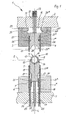
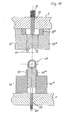
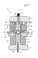
- the Fig. 1 shows a tool 1, which consists essentially of a tool upper part 2 with attached folding jaws 3, 3 * and a slidably held between these workpiece holder 4 and a stationary tool base 5 with guide jaws 6, 6 * mounted thereon and in a slidably held between them Workpiece holder 7 is.
- the upper tool part 2 with the respective components carried by these is perpendicular to a plane E movable, ie lowered in the direction of the lower tool part 5.
- a workpiece to be manufactured 10 inserted into the opened tool becomes according to Fig. 1 a workpiece to be manufactured 10 inserted.
- This workpiece 10 comprises an inner tube 8 and a housing 9, wherein between the tube 8 and the housing 9, a cavity 11 is formed, which may for example be filled with an insulating or Dämmmaterial.
- the housing 9 consists of two sheet metal shells 12 and 13, which have flared edges to which the sheet metal shells 12, 13 abut each other.
- the workpiece 10 is located in a formed on the upper end face of the workpiece holder 7 recess 14. About the workpiece 10 are located at a sufficient distance two hold-down 15, 15 *, which are guided between the folding jaws 3, 3 * and the workpiece holder 4. The distance 16 is the distance of the folding jaws 3, 3 * to each other.
- the workpiece holder 4 and the workpiece holder 7 have a common longitudinal axis L.
- the workpiece holder 7 communicates with its lower end 7 'in interaction with a guided through the tool lower part 5 rod 22 which is supported with its other end on a compression spring 23.
- the lower end of the support elements 17, 17 * interacts with guided through the tool lower part 5 bolts 24, which are each acted upon by compression springs 25.
- the hold-downs 15, 15 * guided between the workpiece holder 4 and the folding jaws 3, 3 are provided with an inwardly directed projection 26, 26 * which projects in each case into a groove 27, 27 * on the surface of the workpiece holder 4.
- the length of the groove 27, 27 * in vertical direction is substantially greater than the thickness of the protrusion 26, 26 *, so that a limited displaceability of the workpiece holder 4 is given to the downholders 15, 15 *.
- the side of the workpiece holder 4 facing the tool upper part 2 interacts with a rod 32 projecting through the tool upper part 2, wherein the other end of the rod 32 is acted on by a compression spring 33.
- the workpiece holder 4 At the end of the workpiece holder 4, which faces the workpiece 10, the workpiece holder 4 has a recess 28 whose contour corresponds to the sheet metal shell 12.
- 3 * are at the end, which is located on the upper tool part 2, slide 29, 29 * arranged in the in Fig. 1 shown outer layer completely outside the distance 16.
- the sliders 29, 29 * At the inner end, the sliders 29, 29 * have a projection 31, 31 * formed by a shoulder 30, 30 *.
- Fig. 1 results in the necessary steps for connecting the sheet metal shells 12, 13 on the basis of FIGS. 2 to 5 described in more detail.
- the tool upper part 2 is first lowered with the components carried by these in the direction of the tool lower part 5, so that the end face of the hold-downs 15, 15 * comes to rest on the edges of the sheet metal shell 12, and then the workpiece holder 4 encloses the sheet metal shell and is also supported on the sheet metal edges.
- the upper tool part is moved downward, whereby a displacement of the workpiece holder 4 and the hold-down 15, 15 * takes place until they come to rest on the upper tool part 2.
- the workpiece holder 4 is moved against the sheet metal shell 12, so that it is received in the recess 28.
- the workpiece holder 4 and the workpiece holder 7 at the connection plane E face .. Since the force of the spring 33 is stronger than that of the springs 23, 25, the workpiece holder 7 is moved in the direction of the lower tool part 5 on further lowering of the upper tool part , so that the edges of the sheet metal shell 13 come to rest on the end faces of the support elements 17, 17 *.
- the slide 29, 29 * so far into the distance 16 in that they are brought into contact with the upper faces of workpiece holder 4 and hold-down 15, 15 * and thus block a longitudinal displacement in the folding jaws 3, 3 *.
- These spacers 37, 37 * are in the distance between folding jaws 3, 3 * and guide jaws 6, 6 * in the direction of the workpiece holder movable.
- it is necessary that the folding jaws 3, 3 * have a distance to the spacers 37, 37 *, which is sufficient to allow a downward movement of the upper tool part 2.
- slides 34, 34 * each have an inclined surface 35, 35 * with an angle of approximately 45 ° to the longitudinal axis of the slide 34, 34 * up.
- the edges of the sheet metal shell 12 were angled downward, the inclined surfaces 35, 35 * extend away from the workpiece holder 7 upwards.
- the Fig. 3 shows the so-called trimming, wherein the tool upper part 2 is lowered and thus the inclined surfaces 35, 35 * exert a force on the angled portions of the edges and bend them in the direction of the workpiece holder 7 around the edges of the sheet metal shell 13 until it is at an angle of take about 45 ° to the longitudinal axis of the tool holder 7.
- the edges of the sheet metal shell 12 are supported on their upper side by means of the hold-downs 15, 15 *.
- the upper die 2 is moved down so that the folding jaws. 3 3 * again surround the edges of the sheet metal shells like this Fig. 4 is apparent.
- the tool upper part 2 is moved downwards so far that the end faces of the support elements 17, 17 * strike the inwardly bent portion of the edges of the sheet metal shell 12 and close the fold by a residual movement in this direction.
- the tool 1 can be opened, wherein the workpiece 10 is located on the workpiece holder 7 and the edges formed by the folding of the sheet metal shells project laterally.
- the rims of the seam joints can be provided with welding points, which are produced for example with a welding tongs.
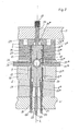
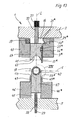
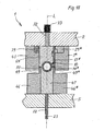
- a tool 1 which consists essentially of a tool upper part 2 and held there bending jaws 43, 43 * and a slidably held between these workpiece holder 44 and a fixed tool lower part 5 with attached guide jaws 46, 46 * and a slidably held between these workpiece holder 47th consists.
- the folding jaws 43, 43 * are adjacent to the upper tool part 2 slide 39, 39 * arranged in the in Fig. 6 shown outer position outside a distance 48, which is formed between the folding jaws 43, 43 *.
- the workpiece holder 44 has at its end directed to the workpiece holder 47 a recess 40, in addition to the lateral hold-down surfaces 41 are formed.
- the tool upper part 2 facing the end of the workpiece holder 44 is in communication with the rod 32, wherein the other end of the rod 32 is acted upon by the compression spring 33.
- the lateral edges next to the recess 42 are very narrow, so that an exact positioning of the sheet metal shells 12, 13, which form the housing, is hardly possible.
- the workpiece holder 47 can be lowered for this purpose, so that the support surfaces 50, 50 * are at the same height as the edges of the recess 42, so that bearing surfaces for the edges of the sheet metal shell 13 are present.
- the first deformation step of the sheet metal shell edges can be performed, which is based on the Fig. 7 is explained.
- the workpiece holder 47 is moved from the workpiece holder 44 to the workpiece base 5 until it rests against this.
- the edges of the sheet metal shells 12, 13 are pressed against each other, and the folding jaws 43, 43 * are pushed so far down that the protruding portions of the edges of the sheet metal shell 12 by means of the bending jaws 43, 43 * at the outer edge of the support stamps 49, 49 * be folded down at least approximately at right angles.
- the rods 22, 32 are each on the outside of the tool base and tool upper part out.
- the tool 1 in the in Fig. 8 shown position first the tool upper part 2 is raised so far that the folding jaws 43, 43 * are located above the sheet metal shell edges. Due to the force of the compression spring 33, the rod 32 holds the workpiece holder 44 in contact with the workpiece 10. The slides 39, 39 * are in Moved towards the rod 32 and block so a relative movement of the workpiece holder. The workpiece holder 47 follows this upward movement due to the force of the compression spring 23. Since the workpiece 10 is in a higher position than the support surfaces 50, 50 * a distance is formed into which the spacers 37, 37 * held slide 34, 34th * be indented from the side.
- the spacers 37, 37 * are slidably guided on the guide jaws 46, 46 * and fit in the distance between folding jaws 43, 43 * and guide jaws 46, 46 *. Since the slide 34 are provided at an angle of approximately 45 ° to the longitudinal axis of the slider 34 inclined inclined surfaces 35, 35 *, as in Fig. 3 If this is the case, the second deformation step of the sheet-metal shell edges, referred to as dressing, takes place, namely the bending of the sections folded down by 90 ° by approximately 45 ° to the workpiece holder 47. The deformation takes place by the lateral movement of the spacers with the slides 34, 34 * in the direction of the workpiece holder 47.
- the upper tool part 2 is moved downward, so that the workpiece holder 44 the Workpiece 10 and the workpiece holder 47 presses down until the workpiece holder rests against the lower tool part 5.
- the support surfaces 50, 50 * of the support punch 49, 49 * reach the inwardly bent portion of the edges of the sheet metal shell 12 and by a residual movement of the upper tool part 2 down the fold is completely closed.
- the folding jaws 43, 43 * again surround the edges of the sheet metal shells, as is the case Fig. 9 is apparent.
- the tool is opened, as in Fig. 10 is shown, wherein the upper tool part 2 is in the highest position. Since the edges of the seaming connections protrude laterally beyond the width of the workpiece holder 47, further operations for securing the seamed connections can be carried out in this position, for example the attachment of spot welds or the angling or Laying the board at the seam connection by means of a bending tool. The accessibility of the board formed at the edges of the sheet is certainly given.
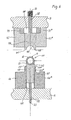
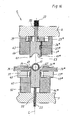
- the Fig. 11 shows an embodiment of the tool 1, which is intended to on the different sides of the housing 9 of the workpiece 10 at the edges of the sheet metal shells 12, 13 on one side of an upwardly shaped seam connection and on the other side to a downwardly shaped seam connection produce.
- a folding jaw 53 * with a slider 51 is arranged on the upper tool part 2 on the right side of the workpiece holder 54, whereas on the left side of the workpiece holder 54, a guide jaw 56 is provided with a support ram 58.
- the workpiece holder 54 is asymmetrical with respect to the central longitudinal axis M, wherein on the right side next to a recess 52, a hold-down surface 59 are provided and formed on the left side, a sharp edge.
- a workpiece holder 57 is arranged, which is formed in mirror image to the workpiece holder 54, with respect to the length but shorter.
- the workpiece holder 57 is provided with a recess 55 in which the workpiece 10 is received.
- the workpiece holder 54 and workpiece holder 57 are each supported by spring-loaded rods 60.
- the Fig. 12 shows an embodiment of the tool 1, in which on the tool upper part 2 on the left side of a folding jaw 43 and on the right side a guide jaw 46 * are arranged. Accordingly, these are attached to the lower tool part 5 folding jaw 43 * and guide jaw 46 opposite. Between the bending jaw 43 and the guide jaw 46 * a workpiece holder 64 is displaceably arranged, which is formed asymmetrically with respect to the longitudinal axis L. In recesses 61, 62 of the folding jaw 43 and guide jaw 46 * slide 63 are arranged, whose function is that the slide 39, 39 * in Fig. 8 equivalent.
- a workpiece holder 67 is slidably disposed, which is also asymmetric with respect to the longitudinal axis L.
- a spacer 37, 37 * with a firmly recorded therein slide 34, 34 * shown which are moved for the purpose of bending the sheet metal section by 45 ° to the workpiece 10 out. Since the sheet metal edge has been deformed by 90 ° downwards by the bending jaw 43, the slide 34 has an upwardly extending inclined surface 35, while the slide 34 * has a downwardly sloping surface 35 *, since the bending jaw 43 * the sheet edge by 90 ° deformed upward.
- the folding jaw 43 * and guide jaw 46 also have suction recesses 61, 62 with slides 63 arranged therein.
- the operation of this tool 1 corresponds to that, as they to the FIGS. 6 to 10 is described, with the only difference being that according to the tool Fig. 12 mirror-inverted working steps are carried out on the edges located on both sides, ie on the left side a fold is produced downwards and on the right side a fold upwards.
- pressure springs are shown as adjusting means for the rods and bolts.
- other adjusting means may be provided, in particular pneumatic cylinders, servomotors or the like.
- the tool can for example be installed in a press, which serves as a drive of the tool for the lifting movement.
- a device such as a pneumatic or hydraulic cylinder.
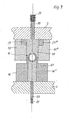
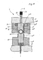
- a tool 1 is shown, which consists essentially of the upper tool part 2 and held there bending jaws 3 *, 43 and a slidably held between these workpiece holder 64 and the lower tool part 5 with attached guide jaws 46, 46 * and the slidably held between them Workpiece holder 47 is.
- the workpiece holder 64 has a recess 63.
- the lower tool part 5 with the parts carried by this corresponds to the embodiment in Fig. 6 , For this reason, the reference numerals for the same parts agree with those of Fig. 6 match.
- the folding jaw 3 * shown on the right side corresponds to that in FIG Fig.
- a hold-down 15 * is arranged between the bending jaw 3 * and the workpiece holder 64 .
- This hold-down 15 * is limited relative to the workpiece holder 64 slidably, as to the Fig. 1 is described.
- the slider 29 * is arranged, which is designed as well as in Fig. 1 and also fulfills the same function.
- the one on the left in Fig. 13 shown Abkantbacke 43 with the slider 39 disposed therein corresponds exactly to the embodiment in Fig. 6 , In the in Fig. 13 shown relative position of the upper tool part 2 to the lower tool part 5, the distance between the workpiece holder 64 and the workpiece holder 47 is large enough that a workpiece 10 can be inserted into the recess 42 at the top of the workpiece holder 47.
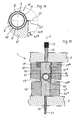
- the Fig. 14 shows an enlarged view of the detail XIV in Fig. 13 ,
- the workpiece 10 which includes an inner tube 8 and a housing 9. Between the tube 8 and the housing 9, a cavity 11 is formed, which may for example be filled with an insulating or insulating material.
- the housing 9 consists of two sheet metal shells 12, 13 which have outwardly flanged edges 61, 62, on which the sheet metal shells 12, 13 abut each other. In the embodiment of Fig. 14 However, it is also possible to perform both edges 61, 62 in the same width.
- the first deformation step can be performed, which is based on the Fig. 15 is explained.
- the edges 61, 62 see. Fig.
- the Fig. 16 shows the upper tool part 2 in a raised position and also the workpiece holder 47 has been returned by the compression spring 23 to the starting position. At the edges 61 of the sheet metal shell 12, the folded portions can be seen.
- the sliders 29 *, 39 are slid toward the rod 32, thus blocking relative movement of the workpiece holder 64. Spacers 37, 37 * with slides 34, 34 * mounted therein are engaged from the side.
- the tool upper part 2 is lowered again until the folding jaws 3 *, 43 are supported on the spacers 37, 37 * and the workpiece holder 64 with the hold-down device 15 * lie on the edges of the sheet metal shell 12.
- the slide 34, 34 * which are inclined at an angle of approximately 45 ° to the longitudinal axis of the slide inclined surfaces 35, 35 *, the trimming of the edges of the sheet metal shell 12 takes place as a second deformation step, namely by a further 45 ° to the workpiece holder 47th out.
- the upper tool part 2 is slightly raised, so that the spacers 37, 37 * can be moved laterally outwards with the slides again.
- the slides 29 * and 39 are again moved away from the rod 32.
- the tool upper part 2 is moved down, as in Fig. 18 is shown.
- the workpiece holder 64 presses the workpiece 10 and the workpiece holder 47 down until the workpiece holder rests on the lower tool part 5.
- the support surfaces 50, 50 * of the support punch 49, 49 * reach the inwardly bent portion of the edges of the sheet metal shell 12 and by a residual movement of the upper tool part 2 down the fold is completely closed.
- a folding of the board of the seaming done.
- a slider 65 is pushed between the underside of the workpiece holder 47 and the lower tool part 5, so that no relative movement between the guide jaws 46, 46 * and the workpiece holder 47 takes place.
- the slide 29 * arranged in the folding jaw 3 * is displaced inwards, so that the shoulder 30 * engages behind the hold-down device 15 *.
- the upper tool part 2 is moved down, whereby the hold-down 15 * flips the board of the right fold, in the present example by 90 °.
- Fig. 13 to 19 only a hold-down 15 * is shown. However, it is also possible to arrange downholders on the right and left, so that a folding of the board of the folds on both sides is possible. In this case, all parts carried by the tool upper part 2 are formed in mirror image to the longitudinal axis L of the workpiece holder 64.
- a significant advantage of the embodiment according to Fig. 13 to 19 is to be seen in that a combination of the simple execution, as in Fig. 6 is shown with the possibility of turning over the board of a fold or both folds is created.
Landscapes
- Engineering & Computer Science (AREA)
- Mechanical Engineering (AREA)
- Bending Of Plates, Rods, And Pipes (AREA)
Priority Applications (1)
| Application Number | Priority Date | Filing Date | Title |
|---|---|---|---|
| EP13005005.7A EP2801418B1 (fr) | 2013-05-07 | 2013-10-19 | Dispositif destiné à relier des coques de tôle à un boîtier d'une pièce au moyen de plis sur les bords des coques de tôle |
Applications Claiming Priority (2)
| Application Number | Priority Date | Filing Date | Title |
|---|---|---|---|
| EP13002421 | 2013-05-07 | ||
| EP13005005.7A EP2801418B1 (fr) | 2013-05-07 | 2013-10-19 | Dispositif destiné à relier des coques de tôle à un boîtier d'une pièce au moyen de plis sur les bords des coques de tôle |
Publications (2)
| Publication Number | Publication Date |
|---|---|
| EP2801418A1 true EP2801418A1 (fr) | 2014-11-12 |
| EP2801418B1 EP2801418B1 (fr) | 2016-01-20 |
Family
ID=48430408
Family Applications (1)
| Application Number | Title | Priority Date | Filing Date |
|---|---|---|---|
| EP13005005.7A Active EP2801418B1 (fr) | 2013-05-07 | 2013-10-19 | Dispositif destiné à relier des coques de tôle à un boîtier d'une pièce au moyen de plis sur les bords des coques de tôle |
Country Status (1)
| Country | Link |
|---|---|
| EP (1) | EP2801418B1 (fr) |
Cited By (1)
| Publication number | Priority date | Publication date | Assignee | Title |
|---|---|---|---|---|
| CN113976751A (zh) * | 2021-10-25 | 2022-01-28 | 陕西科技大学 | 一种基于环形垫片挤压实现板-管连接的方法及装置 |
Citations (6)
| Publication number | Priority date | Publication date | Assignee | Title |
|---|---|---|---|---|
| JPS5871421U (ja) * | 1981-11-02 | 1983-05-14 | 株式会社土屋製作所 | 筒状体縁部のかしめ装置 |
| JP2000051958A (ja) * | 1998-08-07 | 2000-02-22 | Nissan Motor Co Ltd | ヘミング加工方法 |
| US20020116976A1 (en) * | 2001-02-27 | 2002-08-29 | William Patrick | Die hemming assembly and method |
| US6446322B1 (en) * | 2000-05-10 | 2002-09-10 | Tenneco Automotive Operating Company Inc. | Method and apparatus for sealing canisters |
| US20020157441A1 (en) * | 2001-02-27 | 2002-10-31 | William Patrick | Die hemming assembly and method |
| JP2004181498A (ja) * | 2002-12-04 | 2004-07-02 | Honda Motor Co Ltd | ヘミング金型装置 |
-
2013
- 2013-10-19 EP EP13005005.7A patent/EP2801418B1/fr active Active
Patent Citations (6)
| Publication number | Priority date | Publication date | Assignee | Title |
|---|---|---|---|---|
| JPS5871421U (ja) * | 1981-11-02 | 1983-05-14 | 株式会社土屋製作所 | 筒状体縁部のかしめ装置 |
| JP2000051958A (ja) * | 1998-08-07 | 2000-02-22 | Nissan Motor Co Ltd | ヘミング加工方法 |
| US6446322B1 (en) * | 2000-05-10 | 2002-09-10 | Tenneco Automotive Operating Company Inc. | Method and apparatus for sealing canisters |
| US20020116976A1 (en) * | 2001-02-27 | 2002-08-29 | William Patrick | Die hemming assembly and method |
| US20020157441A1 (en) * | 2001-02-27 | 2002-10-31 | William Patrick | Die hemming assembly and method |
| JP2004181498A (ja) * | 2002-12-04 | 2004-07-02 | Honda Motor Co Ltd | ヘミング金型装置 |
Cited By (1)
| Publication number | Priority date | Publication date | Assignee | Title |
|---|---|---|---|---|
| CN113976751A (zh) * | 2021-10-25 | 2022-01-28 | 陕西科技大学 | 一种基于环形垫片挤压实现板-管连接的方法及装置 |
Also Published As
| Publication number | Publication date |
|---|---|
| EP2801418B1 (fr) | 2016-01-20 |
Similar Documents
| Publication | Publication Date | Title |
|---|---|---|
| EP2987566B1 (fr) | Appareil et méthode pour calibrer des surfaces de coupe avec bavure des pièces d'emboutissage ou des découpage de précision | |
| WO2021094433A1 (fr) | Dispositif pour mettre en forme une pièce conductrice placée dans un noyau statorique et procédé correspondant | |
| DE60006917T2 (de) | Geschlossenes Strukturteil | |
| DE68926538T2 (de) | Faltvorrichtung | |
| AT514821A1 (de) | Biegepresse und Biegeverfahren | |
| DE20021021U1 (de) | Vorrichtung zur Bildung einer dreiseitig begrenzten Ecke aus einem ebenflächigen, plattenförmigen Material | |
| DE10030341C2 (de) | Verfahren zur Herstellung eines hebelartigen Nockenfolgers | |
| EP2522464B1 (fr) | Mordache et procédé de fabrication d'un emmanchement par pressage | |
| EP1781430B1 (fr) | Procede et dispositif pour produire un profile creux a soudure longitudinale | |
| EP2873512B1 (fr) | Dispositif de poinçonnage et de soudage de pièces en matière plastique | |
| EP2801418B1 (fr) | Dispositif destiné à relier des coques de tôle à un boîtier d'une pièce au moyen de plis sur les bords des coques de tôle | |
| DE202013004278U1 (de) | Vorrichtung zum Verbinden von Blechschalen zu einem Gehäuse eines Werkstücks mittels Falzen an Rändern der Blechschalen | |
| DE202014010253U1 (de) | Vorrichtung zum Verbinden von Blechschalen zu einem Gehäuse | |
| EP2845663B1 (fr) | Presse plieuse avec un outil de cintrage composé de plusieurs éléments d'outil | |
| DE10062836A1 (de) | Verfahren zur Herstellung eines rohrförmigen Hohlkörpers | |
| EP3606688B1 (fr) | Outil interchangeable pour machine-outil | |
| DE147939C (fr) | ||
| EP2189229A1 (fr) | Procédé destiné à fermer l'extrémité de tuyaux dotés d'une section transversale rectangulaire | |
| DE2721610B1 (de) | Presse zum Vorbiegen von Blechzuschnitten bei der Herstellung von Grossrohren | |
| EP3184189B1 (fr) | Procédé et appareil pour la fabrication d'un support de traverse arrière pour véhicule automobile | |
| DE102022100163B3 (de) | Verfahren zur Herstellung von Blechbauteilen und Vorrichtung hierfür | |
| DE102011051801B4 (de) | Verfahren und Vorrichtung zur Herstellung von Kernspangen und Kernspange | |
| EP3055085B1 (fr) | Dispositif et procédé permettant de produire un ensemble qui contient une pièce munie d'une isolation | |
| DE295993C (fr) | ||
| DE1301297B (de) | Vorrichtung fuer das Stauchen laenglicher Werkstuecke auf Pressen |
Legal Events
| Date | Code | Title | Description |
|---|---|---|---|
| PUAI | Public reference made under article 153(3) epc to a published international application that has entered the european phase |
Free format text: ORIGINAL CODE: 0009012 |
|
| 17P | Request for examination filed |
Effective date: 20131019 |
|
| AK | Designated contracting states |
Kind code of ref document: A1 Designated state(s): AL AT BE BG CH CY CZ DE DK EE ES FI FR GB GR HR HU IE IS IT LI LT LU LV MC MK MT NL NO PL PT RO RS SE SI SK SM TR |
|
| AX | Request for extension of the european patent |
Extension state: BA ME |
|
| R17P | Request for examination filed (corrected) |
Effective date: 20141203 |
|
| RBV | Designated contracting states (corrected) |
Designated state(s): AL AT BE BG CH CY CZ DE DK EE ES FI FR GB GR HR HU IE IS IT LI LT LU LV MC MK MT NL NO PL PT RO RS SE SI SK SM TR |
|
| RIC1 | Information provided on ipc code assigned before grant |
Ipc: B21D 5/06 20060101AFI20150526BHEP Ipc: B21D 39/02 20060101ALI20150526BHEP |
|
| GRAP | Despatch of communication of intention to grant a patent |
Free format text: ORIGINAL CODE: EPIDOSNIGR1 |
|
| INTG | Intention to grant announced |
Effective date: 20150721 |
|
| GRAS | Grant fee paid |
Free format text: ORIGINAL CODE: EPIDOSNIGR3 |
|
| GRAA | (expected) grant |
Free format text: ORIGINAL CODE: 0009210 |
|
| AK | Designated contracting states |
Kind code of ref document: B1 Designated state(s): AL AT BE BG CH CY CZ DE DK EE ES FI FR GB GR HR HU IE IS IT LI LT LU LV MC MK MT NL NO PL PT RO RS SE SI SK SM TR |
|
| REG | Reference to a national code |
Ref country code: GB Ref legal event code: FG4D Free format text: NOT ENGLISH |
|
| REG | Reference to a national code |
Ref country code: CH Ref legal event code: EP |
|
| REG | Reference to a national code |
Ref country code: IE Ref legal event code: FG4D Free format text: LANGUAGE OF EP DOCUMENT: GERMAN |
|
| REG | Reference to a national code |
Ref country code: AT Ref legal event code: REF Ref document number: 771449 Country of ref document: AT Kind code of ref document: T Effective date: 20160215 |
|
| REG | Reference to a national code |
Ref country code: DE Ref legal event code: R096 Ref document number: 502013001824 Country of ref document: DE |
|
| REG | Reference to a national code |
Ref country code: LT Ref legal event code: MG4D Ref country code: NL Ref legal event code: MP Effective date: 20160120 |
|
| PG25 | Lapsed in a contracting state [announced via postgrant information from national office to epo] |
Ref country code: NL Free format text: LAPSE BECAUSE OF FAILURE TO SUBMIT A TRANSLATION OF THE DESCRIPTION OR TO PAY THE FEE WITHIN THE PRESCRIBED TIME-LIMIT Effective date: 20160120 |
|
| PG25 | Lapsed in a contracting state [announced via postgrant information from national office to epo] |
Ref country code: HR Free format text: LAPSE BECAUSE OF FAILURE TO SUBMIT A TRANSLATION OF THE DESCRIPTION OR TO PAY THE FEE WITHIN THE PRESCRIBED TIME-LIMIT Effective date: 20160120 Ref country code: FI Free format text: LAPSE BECAUSE OF FAILURE TO SUBMIT A TRANSLATION OF THE DESCRIPTION OR TO PAY THE FEE WITHIN THE PRESCRIBED TIME-LIMIT Effective date: 20160120 Ref country code: IT Free format text: LAPSE BECAUSE OF FAILURE TO SUBMIT A TRANSLATION OF THE DESCRIPTION OR TO PAY THE FEE WITHIN THE PRESCRIBED TIME-LIMIT Effective date: 20160120 Ref country code: NO Free format text: LAPSE BECAUSE OF FAILURE TO SUBMIT A TRANSLATION OF THE DESCRIPTION OR TO PAY THE FEE WITHIN THE PRESCRIBED TIME-LIMIT Effective date: 20160420 Ref country code: GR Free format text: LAPSE BECAUSE OF FAILURE TO SUBMIT A TRANSLATION OF THE DESCRIPTION OR TO PAY THE FEE WITHIN THE PRESCRIBED TIME-LIMIT Effective date: 20160421 Ref country code: ES Free format text: LAPSE BECAUSE OF FAILURE TO SUBMIT A TRANSLATION OF THE DESCRIPTION OR TO PAY THE FEE WITHIN THE PRESCRIBED TIME-LIMIT Effective date: 20160120 |
|
| PG25 | Lapsed in a contracting state [announced via postgrant information from national office to epo] |
Ref country code: RS Free format text: LAPSE BECAUSE OF FAILURE TO SUBMIT A TRANSLATION OF THE DESCRIPTION OR TO PAY THE FEE WITHIN THE PRESCRIBED TIME-LIMIT Effective date: 20160120 Ref country code: IS Free format text: LAPSE BECAUSE OF FAILURE TO SUBMIT A TRANSLATION OF THE DESCRIPTION OR TO PAY THE FEE WITHIN THE PRESCRIBED TIME-LIMIT Effective date: 20160520 Ref country code: PT Free format text: LAPSE BECAUSE OF FAILURE TO SUBMIT A TRANSLATION OF THE DESCRIPTION OR TO PAY THE FEE WITHIN THE PRESCRIBED TIME-LIMIT Effective date: 20160520 Ref country code: LV Free format text: LAPSE BECAUSE OF FAILURE TO SUBMIT A TRANSLATION OF THE DESCRIPTION OR TO PAY THE FEE WITHIN THE PRESCRIBED TIME-LIMIT Effective date: 20160120 Ref country code: LT Free format text: LAPSE BECAUSE OF FAILURE TO SUBMIT A TRANSLATION OF THE DESCRIPTION OR TO PAY THE FEE WITHIN THE PRESCRIBED TIME-LIMIT Effective date: 20160120 Ref country code: PL Free format text: LAPSE BECAUSE OF FAILURE TO SUBMIT A TRANSLATION OF THE DESCRIPTION OR TO PAY THE FEE WITHIN THE PRESCRIBED TIME-LIMIT Effective date: 20160120 Ref country code: SE Free format text: LAPSE BECAUSE OF FAILURE TO SUBMIT A TRANSLATION OF THE DESCRIPTION OR TO PAY THE FEE WITHIN THE PRESCRIBED TIME-LIMIT Effective date: 20160120 |
|
| REG | Reference to a national code |
Ref country code: DE Ref legal event code: R097 Ref document number: 502013001824 Country of ref document: DE |
|
| PG25 | Lapsed in a contracting state [announced via postgrant information from national office to epo] |
Ref country code: DK Free format text: LAPSE BECAUSE OF FAILURE TO SUBMIT A TRANSLATION OF THE DESCRIPTION OR TO PAY THE FEE WITHIN THE PRESCRIBED TIME-LIMIT Effective date: 20160120 Ref country code: EE Free format text: LAPSE BECAUSE OF FAILURE TO SUBMIT A TRANSLATION OF THE DESCRIPTION OR TO PAY THE FEE WITHIN THE PRESCRIBED TIME-LIMIT Effective date: 20160120 |
|
| PLBE | No opposition filed within time limit |
Free format text: ORIGINAL CODE: 0009261 |
|
| STAA | Information on the status of an ep patent application or granted ep patent |
Free format text: STATUS: NO OPPOSITION FILED WITHIN TIME LIMIT |
|
| PG25 | Lapsed in a contracting state [announced via postgrant information from national office to epo] |
Ref country code: SK Free format text: LAPSE BECAUSE OF FAILURE TO SUBMIT A TRANSLATION OF THE DESCRIPTION OR TO PAY THE FEE WITHIN THE PRESCRIBED TIME-LIMIT Effective date: 20160120 Ref country code: CZ Free format text: LAPSE BECAUSE OF FAILURE TO SUBMIT A TRANSLATION OF THE DESCRIPTION OR TO PAY THE FEE WITHIN THE PRESCRIBED TIME-LIMIT Effective date: 20160120 Ref country code: RO Free format text: LAPSE BECAUSE OF FAILURE TO SUBMIT A TRANSLATION OF THE DESCRIPTION OR TO PAY THE FEE WITHIN THE PRESCRIBED TIME-LIMIT Effective date: 20160120 Ref country code: SM Free format text: LAPSE BECAUSE OF FAILURE TO SUBMIT A TRANSLATION OF THE DESCRIPTION OR TO PAY THE FEE WITHIN THE PRESCRIBED TIME-LIMIT Effective date: 20160120 |
|
| 26N | No opposition filed |
Effective date: 20161021 |
|
| PG25 | Lapsed in a contracting state [announced via postgrant information from national office to epo] |
Ref country code: BE Free format text: LAPSE BECAUSE OF NON-PAYMENT OF DUE FEES Effective date: 20161031 Ref country code: BG Free format text: LAPSE BECAUSE OF FAILURE TO SUBMIT A TRANSLATION OF THE DESCRIPTION OR TO PAY THE FEE WITHIN THE PRESCRIBED TIME-LIMIT Effective date: 20160420 Ref country code: SI Free format text: LAPSE BECAUSE OF FAILURE TO SUBMIT A TRANSLATION OF THE DESCRIPTION OR TO PAY THE FEE WITHIN THE PRESCRIBED TIME-LIMIT Effective date: 20160120 |
|
| REG | Reference to a national code |
Ref country code: CH Ref legal event code: PL |
|
| REG | Reference to a national code |
Ref country code: IE Ref legal event code: MM4A |
|
| REG | Reference to a national code |
Ref country code: FR Ref legal event code: ST Effective date: 20170630 |
|
| PG25 | Lapsed in a contracting state [announced via postgrant information from national office to epo] |
Ref country code: CH Free format text: LAPSE BECAUSE OF NON-PAYMENT OF DUE FEES Effective date: 20161031 Ref country code: FR Free format text: LAPSE BECAUSE OF NON-PAYMENT OF DUE FEES Effective date: 20161102 Ref country code: LI Free format text: LAPSE BECAUSE OF NON-PAYMENT OF DUE FEES Effective date: 20161031 |
|
| PG25 | Lapsed in a contracting state [announced via postgrant information from national office to epo] |
Ref country code: LU Free format text: LAPSE BECAUSE OF NON-PAYMENT OF DUE FEES Effective date: 20161019 |
|
| PG25 | Lapsed in a contracting state [announced via postgrant information from national office to epo] |
Ref country code: IE Free format text: LAPSE BECAUSE OF NON-PAYMENT OF DUE FEES Effective date: 20161019 |
|
| REG | Reference to a national code |
Ref country code: BE Ref legal event code: MM Effective date: 20161031 |
|
| REG | Reference to a national code |
Ref country code: DE Ref legal event code: R082 Ref document number: 502013001824 Country of ref document: DE Representative=s name: PATENTANWAELTE DIPL.-ING. W. JACKISCH & PARTNE, DE Ref country code: DE Ref legal event code: R082 Ref document number: 502013001824 Country of ref document: DE Representative=s name: PATENTANWAELTE DIPL.-ING. WALTER JACKISCH & PA, DE Ref country code: DE Ref legal event code: R081 Ref document number: 502013001824 Country of ref document: DE Owner name: ING. ROLF KOELLE E.K., INHABER MATTHIAS KOELLE, DE Free format text: FORMER OWNER: KOELLE, ROLF, 71665 VAIHINGEN, DE |
|
| PG25 | Lapsed in a contracting state [announced via postgrant information from national office to epo] |
Ref country code: HU Free format text: LAPSE BECAUSE OF FAILURE TO SUBMIT A TRANSLATION OF THE DESCRIPTION OR TO PAY THE FEE WITHIN THE PRESCRIBED TIME-LIMIT; INVALID AB INITIO Effective date: 20131019 |
|
| GBPC | Gb: european patent ceased through non-payment of renewal fee |
Effective date: 20171019 |
|
| PG25 | Lapsed in a contracting state [announced via postgrant information from national office to epo] |
Ref country code: CY Free format text: LAPSE BECAUSE OF FAILURE TO SUBMIT A TRANSLATION OF THE DESCRIPTION OR TO PAY THE FEE WITHIN THE PRESCRIBED TIME-LIMIT Effective date: 20160120 Ref country code: MK Free format text: LAPSE BECAUSE OF FAILURE TO SUBMIT A TRANSLATION OF THE DESCRIPTION OR TO PAY THE FEE WITHIN THE PRESCRIBED TIME-LIMIT Effective date: 20160120 Ref country code: MC Free format text: LAPSE BECAUSE OF FAILURE TO SUBMIT A TRANSLATION OF THE DESCRIPTION OR TO PAY THE FEE WITHIN THE PRESCRIBED TIME-LIMIT Effective date: 20160120 Ref country code: MT Free format text: LAPSE BECAUSE OF FAILURE TO SUBMIT A TRANSLATION OF THE DESCRIPTION OR TO PAY THE FEE WITHIN THE PRESCRIBED TIME-LIMIT Effective date: 20160120 |
|
| PG25 | Lapsed in a contracting state [announced via postgrant information from national office to epo] |
Ref country code: GB Free format text: LAPSE BECAUSE OF NON-PAYMENT OF DUE FEES Effective date: 20171019 |
|
| PG25 | Lapsed in a contracting state [announced via postgrant information from national office to epo] |
Ref country code: AL Free format text: LAPSE BECAUSE OF FAILURE TO SUBMIT A TRANSLATION OF THE DESCRIPTION OR TO PAY THE FEE WITHIN THE PRESCRIBED TIME-LIMIT Effective date: 20160120 Ref country code: TR Free format text: LAPSE BECAUSE OF FAILURE TO SUBMIT A TRANSLATION OF THE DESCRIPTION OR TO PAY THE FEE WITHIN THE PRESCRIBED TIME-LIMIT Effective date: 20160120 |
|
| REG | Reference to a national code |
Ref country code: AT Ref legal event code: MM01 Ref document number: 771449 Country of ref document: AT Kind code of ref document: T Effective date: 20181019 |
|
| PG25 | Lapsed in a contracting state [announced via postgrant information from national office to epo] |
Ref country code: AT Free format text: LAPSE BECAUSE OF NON-PAYMENT OF DUE FEES Effective date: 20181019 |
|
| PGFP | Annual fee paid to national office [announced via postgrant information from national office to epo] |
Ref country code: DE Payment date: 20251021 Year of fee payment: 13 |