EP2801421A1 - Foret hélicoïdal et son procédé de fabrication - Google Patents
Foret hélicoïdal et son procédé de fabrication Download PDFInfo
- Publication number
- EP2801421A1 EP2801421A1 EP13166671.1A EP13166671A EP2801421A1 EP 2801421 A1 EP2801421 A1 EP 2801421A1 EP 13166671 A EP13166671 A EP 13166671A EP 2801421 A1 EP2801421 A1 EP 2801421A1
- Authority
- EP
- European Patent Office
- Prior art keywords
- axis
- drill
- ribs
- manufacturing
- along
- Prior art date
- Legal status (The legal status is an assumption and is not a legal conclusion. Google has not performed a legal analysis and makes no representation as to the accuracy of the status listed.)
- Withdrawn
Links
- 238000004519 manufacturing process Methods 0.000 title claims abstract description 21
- 238000005096 rolling process Methods 0.000 claims description 31
- 238000005520 cutting process Methods 0.000 description 9
- 238000003780 insertion Methods 0.000 description 4
- 230000037431 insertion Effects 0.000 description 4
- 238000005553 drilling Methods 0.000 description 2
- 238000000034 method Methods 0.000 description 2
- 239000004575 stone Substances 0.000 description 2
- QNRATNLHPGXHMA-XZHTYLCXSA-N (r)-(6-ethoxyquinolin-4-yl)-[(2s,4s,5r)-5-ethyl-1-azabicyclo[2.2.2]octan-2-yl]methanol;hydrochloride Chemical compound Cl.C([C@H]([C@H](C1)CC)C2)CN1[C@@H]2[C@H](O)C1=CC=NC2=CC=C(OCC)C=C21 QNRATNLHPGXHMA-XZHTYLCXSA-N 0.000 description 1
- 239000011230 binding agent Substances 0.000 description 1
- 230000000295 complement effect Effects 0.000 description 1
- 239000004567 concrete Substances 0.000 description 1
- 230000007423 decrease Effects 0.000 description 1
- 229910003460 diamond Inorganic materials 0.000 description 1
- 239000010432 diamond Substances 0.000 description 1
- 239000000428 dust Substances 0.000 description 1
- 230000000694 effects Effects 0.000 description 1
- 238000007373 indentation Methods 0.000 description 1
- 238000003754 machining Methods 0.000 description 1
- 239000000463 material Substances 0.000 description 1
- 229910052751 metal Inorganic materials 0.000 description 1
- 239000002184 metal Substances 0.000 description 1
- 230000000737 periodic effect Effects 0.000 description 1
- 239000011150 reinforced concrete Substances 0.000 description 1
- 230000002787 reinforcement Effects 0.000 description 1
- 230000000284 resting effect Effects 0.000 description 1
- 239000011435 rock Substances 0.000 description 1
- 230000007704 transition Effects 0.000 description 1
- UONOETXJSWQNOL-UHFFFAOYSA-N tungsten carbide Chemical compound [W+]#[C-] UONOETXJSWQNOL-UHFFFAOYSA-N 0.000 description 1
- 238000004804 winding Methods 0.000 description 1
Images


Classifications
-
- B—PERFORMING OPERATIONS; TRANSPORTING
- B23—MACHINE TOOLS; METAL-WORKING NOT OTHERWISE PROVIDED FOR
- B23B—TURNING; BORING
- B23B51/00—Tools for drilling machines
- B23B51/02—Twist drills
-
- B—PERFORMING OPERATIONS; TRANSPORTING
- B21—MECHANICAL METAL-WORKING WITHOUT ESSENTIALLY REMOVING MATERIAL; PUNCHING METAL
- B21H—MAKING PARTICULAR METAL OBJECTS BY ROLLING, e.g. SCREWS, WHEELS, RINGS, BARRELS, BALLS
- B21H3/00—Making helical bodies or bodies having parts of helical shape
- B21H3/10—Making helical bodies or bodies having parts of helical shape twist-drills; screw-taps
-
- B—PERFORMING OPERATIONS; TRANSPORTING
- B23—MACHINE TOOLS; METAL-WORKING NOT OTHERWISE PROVIDED FOR
- B23P—METAL-WORKING NOT OTHERWISE PROVIDED FOR; COMBINED OPERATIONS; UNIVERSAL MACHINE TOOLS
- B23P15/00—Making specific metal objects by operations not covered by a single other subclass or a group in this subclass
- B23P15/28—Making specific metal objects by operations not covered by a single other subclass or a group in this subclass cutting tools
- B23P15/32—Making specific metal objects by operations not covered by a single other subclass or a group in this subclass cutting tools twist-drills
-
- E—FIXED CONSTRUCTIONS
- E21—EARTH OR ROCK DRILLING; MINING
- E21B—EARTH OR ROCK DRILLING; OBTAINING OIL, GAS, WATER, SOLUBLE OR MELTABLE MATERIALS OR A SLURRY OF MINERALS FROM WELLS
- E21B10/00—Drill bits
- E21B10/44—Bits with helical conveying portion, e.g. screw type bits; Augers with leading portion or with detachable parts
- E21B10/445—Bits with helical conveying portion, e.g. screw type bits; Augers with leading portion or with detachable parts percussion type, e.g. for masonry
-
- B—PERFORMING OPERATIONS; TRANSPORTING
- B23—MACHINE TOOLS; METAL-WORKING NOT OTHERWISE PROVIDED FOR
- B23B—TURNING; BORING
- B23B2251/00—Details of tools for drilling machines
- B23B2251/40—Flutes, i.e. chip conveying grooves
- B23B2251/406—Flutes, i.e. chip conveying grooves of special form not otherwise provided for
Definitions
- the present invention relates to a helical drill and a manufacturing method for a helical drill, in particular for twist drills for the drilling of stone and concrete together with reinforcements.
- Drills for working stone, reinforced concrete, etc. are for example from the US 7,021,872 known.
- the helix is primarily intended to remove cuttings from a borehole.
- the classic helical coils have proven themselves for this, not only because of the secured transport of cuttings, but also because of the moderate production effort.
- the classic helix is subject to compromises in other properties, particularly because of the manufacturing processes used.
- One aspect is the friction of the helix on the borehole wall.
- the twist drill according to the invention has a drill head, a continuous two, three to six-speed helix and a spigot, which are arranged successively on a drill axis.
- the helix has a radially outer dimension varying periodically, two, three to six times per revolution around the drill axis.
- the outer dimension preferably varies by a maximum of 10%, and preferably by at least 2%.
- the helical drill has a continuous helix, which contributes along its entire circulation to the removal of the Bohrgut.
- the varying diameter of the helix leads to the helix resting against the borehole wall only at a few points. As a result, the friction can be reduced.
- the inventive manufacturing method for a twist drill has the following steps.
- a plurality of depressions are rolled into the lateral surface of a blank to form a network of ribs.
- the mutually parallel first ribs extend along the axis of the blank and the mutually parallel second ribs extend below an inclination angle obliquely to the first ribs.
- the first ribs have portions lying between adjacent second ribs. Grooves are rolled into these sections.
- a drill head is formed at a front side of the rolled blank.
- the two-phase rolling process is an efficient production method for the drill, which at the same time allows a new design freedom for the shape of the drill.
- the depressions can be rolled in rows parallel to one another and oriented along the axis.
- the recesses adjacent the axis may overlap along the axis.
- Circumferentially adjacent recesses may be circumferentially spaced.
- a surface of the recesses is concave along each direction.
- the recesses deviate greatly in shape from the helix to be produced in relation to the curvature. It turns out, however, that for the production of a desired coil, the concave depressions are sufficient.
- the recesses make lower demands on the rolling tools than for a direct rolling in of a groove in the form of the helix.
- An embodiment provides that the grooves extend parallel to the second ribs.
- a surface of the grooves may be convex in a direction parallel to the second ribs.
- the grooves overflow the depressions.
- the grooves coincide with the convex course of the helical bottom of a classic helix.
- An embodiment provides that the grooves are rolled with a deviating depth of less than 10% of a depth of the recesses.
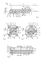
- Fig. 1 shows schematically simplified an exemplary twist drill.
- the helical drill 1 has along a drill axis 2 successively a drill head 3 , a helical coil 4 and a spigot. 5
- the illustrated twist drill 1 is designed for the machining of reinforced rock, in particular for a rotary movement superimposed M aceaelformat.
- the drill head 3 has four faces in the impact direction 6 chisel edge. 7
- the chisel edges 7 are each formed as a crossing line of a front in the direction of rotation of the drill 1 surface and a trailing surface, both of which are inclined relative to the drill axis 2 and inclined to each other by at least 60 degrees.
- the chisel edges 7 extend substantially in the radial direction, for example starting from a tip 8 of the drill head 3 up to an edge of the drill head 3 , where the chisel edges 7 are preferably set back relative to the tip 8 in the direction of impact 6 .
- An inclination of the chisel edges 7 with respect to the axis 3 can be constant in the radial direction or be less in the region of the tip 8 than at the edge.
- the chisel edge 7 can run perpendicular to the drill axis 2 at the edge.
- a demolition edge 9 which is parallel to the axis 3 .
- the demolition edge 9 is preferably radially beyond the helix 4 addition.
- the drill head 3 is provided at its periphery with parallel to the drill axis 2 extending discharge channels 10 , along which the drill dust can be transported from the well.
- the discharge channels 10 are arranged in the circumferential direction 11 between the chisel edges 7 .
- the drill head 3 is preferably a continuous sintered cemented carbide body containing, for example, tungsten carbide and a metallic binder.
- the illustrated drill head 3 has two pairs of differently shaped chisel edges, of which the chisel edges forming the point 8 are referred to as main cutting edges and the other pair as secondary cutting edges. Instead of four, the bit body may also have two, eg only the major cutting edges, or three or more than four cutting edges.
- the helix 4 has a plurality of helical spiral webs 12, which are arranged around a rotationally symmetrical core 13 .
- the number of spiral webs 12 is preferably equal to the number of chisel edges 7.
- the exemplary helix 4 has four helical webs 12, ie is four-start.
- the spiral webs 12 are arranged for example in the circumferential direction 11 at equal angular intervals, for example at a distance of 90 degrees.
- the axial distance 14 between adjacent spiral webs 12 is preferably the same size and along the drill axis 2 constant. The axial distance 14 is in the example a quarter of the pitch of a spiral web 12th
- the spiral webs 12 preferably have the same dimensions and the same shape.
- the surface of the spiral web 12 has two flanks 15, 16 which helically rotate about the drill axis 2.
- the first of the flanks 15 continuously faces the drill head 3 , and the second of the flanks 16 is directed away from the drill head 3 .
- the radial distance of the first flank 15 to the drill axis 2 increases substantially monotonically in a circumferential direction 11
- the radial distance of the second flank 16 drops substantially monotonically in the circumferential direction 11 .
- the transition between the first flank 15 and the second flank 16, ie their radially projecting edges, forms the helical ridge 17.
- the helical ridge 17 can be a helical band oriented substantially perpendicular to the drill axis 2 , or geometrically simplified a continuous one around the drill axis 2 be winding line.
- the along the drill axis 2 Uninterrupted line includes from each of all perpendicular to the drill axis 2 oriented cross sections through the spiral web 12, the point which has the largest distance 18 to the drill axis 2 .
- the distance 18 is referred to below as the height 18 of the coil back 17 .
- a helical spiral base 19 extends in each case between two adjacent spiral webs 12.
- the spiral bottom 19 may be a continuous helical line or a band oriented substantially perpendicular to the drill axis 2 .
- the helical bottom 19 has the smallest radial distance to the drill axis 2.
- the core 13 is exposed at the helical bottom 19 .
- a classic helix has a uniform shape and dimension of the cross section along the axis.
- the cross-section in a plane can be congruent to all cross sections in parallel planes only by a rotation around the drill axis.
- the height of the Wendelschens is constant.
- Fig. 2 shows a first cross section in the plane II-II perpendicular to the drill axis 2
- Fig. 3 shows a second cross section in the plane III-III parallel to the plane II-II.
- the offset between the two planes II-II, III-III corresponds to half the period, ie half of the axial distance 14 between two adjacent helical turns 12.
- the helix 4 is inscribed in a cylinder with a constant outer radius 20 .
- a full cylinder (core 13) with a constant inner radius 21 can be written into the helix 4 .
- the cylinders are dashed in the Fig. 2 to Fig. 4 located.
- the radial outer dimension 18 of the helix 4 changes periodically along the drill axis 2.
- the radial outer dimension 18 is greater in the plane II-II than in the plane III-III. Accordingly, the spiral is located only at certain points 4 on to the cylinder circumscribing.
- the radial outer dimension 18 preferably varies by up to 10%, preferably by at least 2%. The variation of the amplitude is limited with regard to a continuous transport of cuttings.
- the radial outer dimension 18 varies slowly, for example three times to six times per complete revolution of a Wendelenburgens 17, here four times , for example.
- the profile 22 of the helix 4, defined by the varying outer dimension 18, has a corresponding threefold to sixfold rotational symmetry.
- Fig. 4 shows a section of the coil back 17 in an unrolled about the drill axis 2 representation.
- the section IV-IV is helical and follows the spiral bottom 19 (abscissa and ordinate are not to scale).
- the spiral ridge 17 has a to 18 along the drill axis 2 periodically varying height in the respective direction perpendicular to the drill axis 2 cross-sections furthest from the drill axis 2 points (spiral ridge 17) have a different distance (height 18) to the drill axis.
- the height 18 has along the drill axis 2 at constant intervals 14 periodically successive maxima, hereinafter referred to as summit 23 , and lying between the peaks 23 minima, hereinafter referred to as saddle 24 .
- the height 18 varies between the peak 23, ie the maximum value, and the saddle 24, the minimum value, by up to 10%, preferably by at least 3%.
- the coil 4 is located on the drilling only with the peaks 23 on the borehole wall. As a result, friction losses, especially in deep boreholes, can be reduced.
- the helical ridge 17 preferably has the same number of peaks 23 per revolution around the drill axis 2 as the helix 4 has spiral webs 12 .
- An axial distance between adjacent peaks 23 is preferably equal to the axial spacing 14 of adjacent spiral ridge 17.
- a distance between two peaks 23 of a helical ridge 17 in the circumferential direction 11 is equal to the division of the circumference by the plurality of helical ridges 12, in the shown example 90 degrees.
- the spiral webs 12 preferably have the same dimension, the same shape and their arrangement is rotationally symmetrical.
- the summit 23 of a Wendelschens 17 is located in the circumferential direction 11 of the summit 23 of the adjacent Wendelschens 17 opposite.
- the peak 23 of a helical ridge 17 is thus preferably each with a peak 23 of each of the other spiral ridge 17 in a plane II-II perpendicular to the axis of the drill 2.
- Fig. 2 example shown has in the plane II-II each of the four coil 4 a summit 23.
- each peak 23 lies on one of four straight lines that run parallel to the drill axis 2 and in the same Angular distances, here 90 degrees, around the drill axis 2 are arranged.
- the number of straight lines corresponds to the number of spiral webs 12.
- the saddles 24, ie the minima of the height 18, are approximately halfway between two successive peaks 23.
- the helical base 19 may have a radial distance 25 that is constant along the drill axis 2 . In the exemplary embodiment results in a low periodic variation of the coil base 19 along the drill axis 2.
- the minima 26 of the radial distance 25 of the coil base 19 are preferably with the peaks 23 of the spiral ridge in direction perpendicular to the drill axis 2 planes II-II.
- the maxima 27 of the radial distance 25 of the coil base 19 are preferably with the saddles 24 of the coil back in planes perpendicular to the drill axis 2 levels III-III.
- the helical bottom 19 and the coil back 17 thus have an opposite inclination to the drill axis 2 .
- the manufacturing method described below for the twist drill 1 is mainly concerned with the production of the helix 4.
- the described production of the insertion end 5 and the production or attachment of the drill head 3 are only preferred examples.
- FIGS. 5 and 6 schematically show a first processing of a blank 28 in longitudinal section VV or section VI-VI.
- the blank 28 is, for example, a cylindrical wire.
- the cross-section of the blank 28 is preferably circular in order to facilitate procurement, but may also have another approximately circular shape, eg polygonal, oval.
- the illustrated manufacturing method elongates the blank 28 to a desired length prior to the subsequent forming steps, eg, the length of the coil 4 or the length of the helical drill 1 including the insertion end 5.
- the coil 4 is first formed into the blank 28 and the formed Blank subsequently cut into several coils 4 .
- the blank 28 is provided with a plurality of depressions 30 by a first stand with four rolling tools 29 .
- the rolling of the recesses 30 is effected by longitudinal rollers.
- a driving direction 31 of the blank 28 is parallel to its axis 2.
- the rolling tools 29 roll on the blank 28 parallel to the axis 2 of the blank 28 .
- An axis of rotation 32 or pivot axis of the rolling tools 29 is perpendicular to the axis 2 and the advancing direction 31 of the blank 28th
- the rolling tools 29 are preferably identical. Further, the rolling tools 29 are arranged at equal angular intervals about the axis 2 of the blank 28 . Each of the rolling tools 29 thus processes a different angle section 33 of the blank 28 and forms in the angular section 33 a series of successive depressions 30 along the axis 2 . The distance along the axis 28 of adjacent recesses 30 is preferably constant.
- the rolling tool 29 has substantially the shape of a helical gear with a plurality of teeth 34 arranged on the circumference .
- the teeth 34 are, for example, prismatic, ie their cross section is constant along the axis of rotation 32 .
- cross section exemplified is part-circular, ie, the teeth 34 have the shape of a cylinder segment.
- the head line 35 of the teeth 34 is inclined with respect to the axis of rotation 32 .
- An inclination angle 36 between the rotation axis 32 and the head line 35 is in the range between 30 degrees and 60 degrees.
- the teeth 34 are preferably all the same.
- FIGS. 7, 8 and 9 show an enlarged cross section in the plane VII-VII
- Fig. 8 a side view in direction VIII
- Fig. 9 another side view towards IX
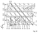
- Fig. 10 an unrolled about the axis 2 representation.
- the indentations 30 formed in the halfling 37 have, for example, an elliptical or diamond-shaped outline.
- the recesses 30 are designed the same.
- a longitudinal axis 38 of the recess 30 extends through the two farthest ends of the recess 30 and thus defines its largest dimension 39.
- the dimension 39 of the recess 30 along the longitudinal axis 38 is preferably more than twice as large as the dimension 40 of the recess 30th perpendicular to the longitudinal axis 38.
- the longitudinal axis 38 of the recess 30 is inclined relative to the axis 2 of the halfling 37 by an inclination angle 41 .
- the inclination angle 41 is preferably between 30 degrees and 60 degrees.
- the surface 42 of the recess 30 is preferably concave cylindrical or concave prismatic.
- the recess 30 has substantially the shape of a section of a circular or elliptical cylinder with the cylindrical blank 28.
- the recess 30 is parallel to the longitudinal axis 38 not curved and concave in all other directions with a constant or varying, positive curvature.
- the recess 30 may be lenticular.
- the recess 30 is convex in each direction, ie, positively curved, also along the longitudinal axis 38.
- the curvature of the surface 42 parallel to the longitudinal axis 38 is greater than the curvature of the surface 42 perpendicular to the longitudinal axis 38.
- a negative curvature, ie a concave Line, the recess 30 is desired in any embodiment, not even along the least strongly curved longitudinal axis 38th
- the depressions 30 are arranged in four rows 43 by way of example.
- the rows 43 are preferably oriented parallel to the axis 2 , corresponding to each of the rows 43 in a different angle portion 33.
- the circumferentially 11 adjacent depressions 30 thus have no overlap in the circumferential direction 11. A rotation of the blank 28 about its axis 2 for this purpose prevented during the rolling of the wells 30 .
- the adjacent in the circumferential direction 11 rows 43 are each separated by an axially extending rib 44 .
- the axially extending ribs 44 are substantially parallel to the axis 2 and extend without interruption, preferably over the entire length of the blank 28, at least along the section of the blank 28 provided with the depressions 30.
- a radial height 45 of the ribs 44, their outer dimension relative to the axis 2 is always the largest radial dimension in each cross section.
- the outer dimension of the halfling 37 is greater than the outer dimension of the original blank 28.
- the recess 30 has a lowest point 46, which is at a minimum distance 21 to the axis 2 .
- the lowest point 46 lies in the middle of the preferably largely symmetrical depression 30 .
- the distance of the surface 42 to the axis 2 increases monotonically, preferably strictly monotone, in each direction with the distance to the lowest point 46.
- the deepest points 46 of the recesses 30 of a row 43 are preferably on a line 47 parallel to the axis 2 ,
- the rear end 14 in the direction 6 of the front recess 48 is located in the direction 6 behind the plane 11.
- Vice versa which lies in the direction of front end 50 6 the rear recess 49 in the direction 6 in front of the plane 11.
- the adjacent recesses 30 within a row 43 are separated by ribs 52 inclined to the axis 2 , followed by inclined ribs 52 .
- the inclined ribs 52 are mutually parallel and inclined at an inclination angle 53 relative to the axis 2 .
- the oblique ribs 52 extend continuously equal to the axial ribs 44 over the entire length of the blank 28, or the entire area with the depressions 30.
- the oblique ribs 52 project beyond the cross section of the original blank 28 .
- the pushed out of the wells 30 material is distributed to the ribs 44, 52 .
- a height of the inclined ribs 52 may be less than the height of the axial ribs 44 , in particular in the overlapping region of adjacent recesses 30.
- the axial ribs 44 and the oblique ribs 52 intersect at points of intersection 54.
- the ribs 44, 52 form a net-like surface structure whose interspaces are formed by the recesses 30 .
- the meshed halfling 37 is fed to a second stand with four second rolling tools 55 .
- the second frame rolls the recesses 30 by longitudinal rollers in continuous, shown four, helical grooves 15 to.
- the rotary or pivot axes of the rolling tools 55 are perpendicular to the feed direction and axis 2 of the halfling 37.
- the second rolling tools 55 are preferably the same and arranged about the axis 2, preferably at equidistant angles.
- Each of the rolling tools 55 processes a different angle portion 15 of the half-blank 37.
- the circumferentially adjacent 11 rolling tools 55 touch each other preferably such that the roll surfaces form a closed ring around the axis 2 of the half-Ling 37th
- An axial portion of the halfling 37 is simultaneously deformed from all sides and the axial portion continuously shifts along the axis 2.
- the halfling 37 is fed to the second framework with a defined angular orientation.
- the second stand is rotated 45 degrees from the first stand.
- the axial ribs 44 are each centrally or approximately centrally to the rolling surfaces.
- the angle section 15 machined by the second rolling tool 55 overlaps with exactly two adjacent rows 43 of the recesses 30 of the halfling 37.
- the second rolling tool 55 thereby forms one of the axial ribs 44 . Accordingly, the number of the second rolling tools 55 is equal to the number of the axial ribs 44.
- the angle section 15 covered by the second rolling tool 55 may be bounded in the circumferential direction 11 by the deepest points 46 of the recesses 30 of the two machined rows 43 .
- the rolling tools 55 have a shape analogous to a helical gear with a plurality of teeth 56.
- a head line 16 of the teeth 56 is inclined relative to the axis of rotation 57 of the rolling tools 55 by a an inclination angle 58 .
- the inclination angle 58 is between 30 degrees and 60 degrees and is selected according to the desired helical pitch.
- the inclination angle 58 of the helical pitch coincides with the inclination angle 53 of the oblique ribs 52 to less than 5 degrees to compensate for elongation effects.
- the teeth 56 Deviating from a prismatic shape, have a circularly concave curved head line 16.
- the curvature is approximately equal to the curvature of the spiral base 19 to be produced.
- a height of the teeth 56 decreases monotonically along the axis of rotation from the edge to the middle and then to monotonically towards the edge.
- the teeth 56 preferably contact, during rolling with the edge of the head line 16, the deepest points 46 of the halfling 37 without reshaping them.
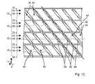
- Fig. 13 schematically shows the rolled out from the second frame halfling 37.
- the rolled from the first frame recesses 30 define the course of the axial ribs 44 and the inclined ribs 52.
- the second rolling tools 55 roll over the axial ribs 44 with rhombic grooves 59.
- the grooves 59 are arranged in rows 60 parallel to the axis 2 , which correspond to the respective angle sections 15 .
- the slope 58 of the teeth 56 translates into the inclined diamond shape of the grooves 59.
- the grooves 59 are first defined in the circumferential direction 11 defined to reform the axial ribs 44 . Second, the grooves 59 are positioned along the axis 2 between the oblique ribs 52 . The axial rib 44 is thus substantially transformed only between its intersection points 54 with the oblique ribs 52 .
- the grooves 59 are bounded along the axis 2 by the second ribs 52 and in the circumferential direction 11, more precisely in a direction parallel to the second ribs 52, open.
- the dimension of the groove 59 is correspondingly along the axis 2 equal to or up to 20% less than that of the axial dimension of the recess 30.
- the dimension of the grooves 59 in Circumferential direction 11 is greater than half the dimension of the recesses 30 in the circumferential direction 11th
- the surface 42 of the grooves 59 is concave parallel to the oblique ribs 52 , ie has a negative curvature.
- the grooves 59 preferably have the curvature of the helical bottom 19.
- the smallest distance 26 of the grooves 59 to the axis 28 deviates by less than 10% from the distance 21 of the lowest point 46 to the axis 28 from.
- the drill head 3 is preferably made of monolithic metal carbide.
- An end face of the manufactured helix 4 is provided with a seat, in which the drill head 3 is inserted and materially connected.
- the seat may have complementary to the edges formed slots to insert the drill head 3 partially in the helix 4 positively.
- the drill head 3 may be butt welded or brazed to the helix 4 .
- the drill head 3 opposite end of the coil 4 is provided with the insertion end 5 .
- the blank 28 is left in its originally cylindrical shape, for example, on a section provided for the insertion end 5 .
- Grooves for a rotary drive and a lock are molded or milled into the end.
- the spigot 5 can also be made separately and welded or brazed to the helix 4 .
Landscapes
- Engineering & Computer Science (AREA)
- Mechanical Engineering (AREA)
- Mining & Mineral Resources (AREA)
- Geology (AREA)
- Life Sciences & Earth Sciences (AREA)
- Environmental & Geological Engineering (AREA)
- Fluid Mechanics (AREA)
- Physics & Mathematics (AREA)
- General Life Sciences & Earth Sciences (AREA)
- Geochemistry & Mineralogy (AREA)
- Drilling Tools (AREA)
- Processing Of Stones Or Stones Resemblance Materials (AREA)
- Earth Drilling (AREA)
Priority Applications (6)
| Application Number | Priority Date | Filing Date | Title |
|---|---|---|---|
| EP13166671.1A EP2801421A1 (fr) | 2013-05-06 | 2013-05-06 | Foret hélicoïdal et son procédé de fabrication |
| US14/889,125 US10245657B2 (en) | 2013-05-06 | 2014-04-29 | Twist drill and production method |
| KR1020157034689A KR101803300B1 (ko) | 2013-05-06 | 2014-04-29 | 트위스트 드릴 및 제조 방법 |
| PCT/EP2014/058684 WO2014180709A1 (fr) | 2013-05-06 | 2014-04-29 | Foret hélicoïdal et procédé de fabrication dudit foret |
| EP14720592.6A EP2994255B1 (fr) | 2013-05-06 | 2014-04-29 | Foret hélicoïdal et son procédé de fabrication |
| CN201480025651.4A CN105209190B (zh) | 2013-05-06 | 2014-04-29 | 麻花钻及制造方法 |
Applications Claiming Priority (1)
| Application Number | Priority Date | Filing Date | Title |
|---|---|---|---|
| EP13166671.1A EP2801421A1 (fr) | 2013-05-06 | 2013-05-06 | Foret hélicoïdal et son procédé de fabrication |
Publications (1)
| Publication Number | Publication Date |
|---|---|
| EP2801421A1 true EP2801421A1 (fr) | 2014-11-12 |
Family
ID=48288914
Family Applications (2)
| Application Number | Title | Priority Date | Filing Date |
|---|---|---|---|
| EP13166671.1A Withdrawn EP2801421A1 (fr) | 2013-05-06 | 2013-05-06 | Foret hélicoïdal et son procédé de fabrication |
| EP14720592.6A Active EP2994255B1 (fr) | 2013-05-06 | 2014-04-29 | Foret hélicoïdal et son procédé de fabrication |
Family Applications After (1)
| Application Number | Title | Priority Date | Filing Date |
|---|---|---|---|
| EP14720592.6A Active EP2994255B1 (fr) | 2013-05-06 | 2014-04-29 | Foret hélicoïdal et son procédé de fabrication |
Country Status (5)
| Country | Link |
|---|---|
| US (1) | US10245657B2 (fr) |
| EP (2) | EP2801421A1 (fr) |
| KR (1) | KR101803300B1 (fr) |
| CN (1) | CN105209190B (fr) |
| WO (1) | WO2014180709A1 (fr) |
Cited By (1)
| Publication number | Priority date | Publication date | Assignee | Title |
|---|---|---|---|---|
| WO2016091431A1 (fr) * | 2014-12-09 | 2016-06-16 | Robert Bosch Gmbh | Outil de perçage |
Families Citing this family (6)
| Publication number | Priority date | Publication date | Assignee | Title |
|---|---|---|---|---|
| EP3012039A1 (fr) * | 2014-10-23 | 2016-04-27 | HILTI Aktiengesellschaft | Foret hélicoïdal et son procédé de fabrication |
| US12594611B2 (en) * | 2019-07-09 | 2026-04-07 | Kyocera Corporation | Rotary tool and method for manufacturing machined product |
| KR102775962B1 (ko) | 2019-07-12 | 2025-03-07 | 엘티소재주식회사 | 헤테로고리 화합물 및 이를 포함하는 유기 발광 소자 |
| CN110842206B (zh) * | 2019-11-12 | 2021-08-31 | 丹阳市剑庐工具有限公司 | 一种六角高扭钻柄的制备方法 |
| EP3831507A1 (fr) * | 2019-12-06 | 2021-06-09 | Hilti Aktiengesellschaft | Procédé de fabrication d'un foret |
| WO2026059947A1 (fr) * | 2024-09-11 | 2026-03-19 | Milwaukee Electric Tool Corporation | Manchon pour insert de forage et son procédé de fabrication |
Citations (5)
| Publication number | Priority date | Publication date | Assignee | Title |
|---|---|---|---|---|
| EP0470354A1 (fr) * | 1990-08-06 | 1992-02-12 | fischerwerke Artur Fischer GmbH & Co. KG | Foret à fabriquer des trous cylindriques |
| FR2808462A1 (fr) * | 2000-05-05 | 2001-11-09 | Diager | Foret de percage |
| EP1621274A1 (fr) * | 2004-07-27 | 2006-02-01 | BLACK & DECKER INC. | Foret |
| US7021872B2 (en) | 2001-11-30 | 2006-04-04 | Hilti Aktiengesellschaft | Rock drill |
| DE102011085187B3 (de) * | 2011-10-25 | 2012-12-13 | Hilti Aktiengesellschaft | Bohrer und Herstellungsverfahren für einen Bohrer |
Family Cites Families (4)
| Publication number | Priority date | Publication date | Assignee | Title |
|---|---|---|---|---|
| DE10053342A1 (de) * | 2000-10-27 | 2002-05-08 | Hilti Ag | Wendelbohrer |
| US6601659B2 (en) * | 2001-05-17 | 2003-08-05 | Hilti Aktiengesellschaft | Twist drill |
| CN101116938A (zh) * | 2007-08-30 | 2008-02-06 | 宁波华刃工具有限公司 | 加工麻花钻螺旋沟槽的方法及机加工沟槽机沟槽定位装置 |
| CN202506878U (zh) * | 2012-03-06 | 2012-10-31 | 江海青 | 一种尖头定位式麻花钻 |
-
2013
- 2013-05-06 EP EP13166671.1A patent/EP2801421A1/fr not_active Withdrawn
-
2014
- 2014-04-29 EP EP14720592.6A patent/EP2994255B1/fr active Active
- 2014-04-29 CN CN201480025651.4A patent/CN105209190B/zh active Active
- 2014-04-29 KR KR1020157034689A patent/KR101803300B1/ko active Active
- 2014-04-29 WO PCT/EP2014/058684 patent/WO2014180709A1/fr not_active Ceased
- 2014-04-29 US US14/889,125 patent/US10245657B2/en active Active
Patent Citations (5)
| Publication number | Priority date | Publication date | Assignee | Title |
|---|---|---|---|---|
| EP0470354A1 (fr) * | 1990-08-06 | 1992-02-12 | fischerwerke Artur Fischer GmbH & Co. KG | Foret à fabriquer des trous cylindriques |
| FR2808462A1 (fr) * | 2000-05-05 | 2001-11-09 | Diager | Foret de percage |
| US7021872B2 (en) | 2001-11-30 | 2006-04-04 | Hilti Aktiengesellschaft | Rock drill |
| EP1621274A1 (fr) * | 2004-07-27 | 2006-02-01 | BLACK & DECKER INC. | Foret |
| DE102011085187B3 (de) * | 2011-10-25 | 2012-12-13 | Hilti Aktiengesellschaft | Bohrer und Herstellungsverfahren für einen Bohrer |
Cited By (1)
| Publication number | Priority date | Publication date | Assignee | Title |
|---|---|---|---|---|
| WO2016091431A1 (fr) * | 2014-12-09 | 2016-06-16 | Robert Bosch Gmbh | Outil de perçage |
Also Published As
| Publication number | Publication date |
|---|---|
| CN105209190B (zh) | 2017-08-25 |
| EP2994255A1 (fr) | 2016-03-16 |
| CN105209190A (zh) | 2015-12-30 |
| WO2014180709A1 (fr) | 2014-11-13 |
| KR101803300B1 (ko) | 2017-12-01 |
| EP2994255B1 (fr) | 2019-03-20 |
| US20160074945A1 (en) | 2016-03-17 |
| US10245657B2 (en) | 2019-04-02 |
| KR20160006196A (ko) | 2016-01-18 |
Similar Documents
| Publication | Publication Date | Title |
|---|---|---|
| EP2994255B1 (fr) | Foret hélicoïdal et son procédé de fabrication | |
| EP1340573B1 (fr) | Procédé de fabrication pour un foret ou une fraise | |
| DE69705038T2 (de) | Wendelbohrer mit asymmetrisch beabstandeten stützrippen | |
| EP2861373B1 (fr) | Procédé et outil de création d'un filetage dans une pièce | |
| EP2934802B1 (fr) | Foret hélicoïdal | |
| EP2771143B1 (fr) | Mèche et procédé de fabrication d'une mèche | |
| DE102011001772A1 (de) | Gewindeerzeugungswerkzeug zum Herstellen eines Gewindes in einem Werkstück | |
| DE102009028040A1 (de) | Kombinationswerkzeug für die Strukturierung von Oberflächen | |
| WO2015188998A1 (fr) | Fraise à fileter | |
| WO2016150534A1 (fr) | Foret pour le perçage de stratifiés | |
| DE102013210355B4 (de) | Zerspanungswerkzeug sowie Verfahren zur Herstellung eines Zerspanungswerkzeug | |
| WO2016202768A1 (fr) | Foret et procédé de fabrication | |
| DE19915303A1 (de) | Bohrwerkzeug und Verfahren zu seiner Herstellung | |
| WO2017102417A1 (fr) | Procédé de fabrication, châssis d'outil et foret | |
| EP3209442A1 (fr) | Foret hélicoïdal et procédé de fabrication | |
| WO1998054435A1 (fr) | Outil de perçage | |
| EP2699401A1 (fr) | Outil de perçage et procédé de fabrication d'un outil de perçage | |
| EP3142819B1 (fr) | Outil permettant de rendre une surface métallique rugueuse et procédé pour rendre une surface métallique rugueuse avec un tel outil | |
| EP3477127B1 (fr) | Vis destinée à être vissée dans un trou de forage | |
| DE102008062298B4 (de) | Bohrkörper | |
| DE10243403A1 (de) | Verfahren zur Herstellung eines Werkzeugs, insbesondere eines Bohrers oder Fräsers | |
| DE19520699A1 (de) | Rollwerkzeug zum Walzen eines mehrgängigen Steigungsprofils | |
| EP3515640B1 (fr) | Foret | |
| WO1998054434A1 (fr) | Outil de forage, notamment fleuret a rocher | |
| DE102024200304A1 (de) | Bohrer sowie Verfahren zur Herstellung eines Bohrers |
Legal Events
| Date | Code | Title | Description |
|---|---|---|---|
| PUAI | Public reference made under article 153(3) epc to a published international application that has entered the european phase |
Free format text: ORIGINAL CODE: 0009012 |
|
| 17P | Request for examination filed |
Effective date: 20130506 |
|
| AK | Designated contracting states |
Kind code of ref document: A1 Designated state(s): AL AT BE BG CH CY CZ DE DK EE ES FI FR GB GR HR HU IE IS IT LI LT LU LV MC MK MT NL NO PL PT RO RS SE SI SK SM TR |
|
| AX | Request for extension of the european patent |
Extension state: BA ME |
|
| STAA | Information on the status of an ep patent application or granted ep patent |
Free format text: STATUS: THE APPLICATION IS DEEMED TO BE WITHDRAWN |
|
| 18D | Application deemed to be withdrawn |
Effective date: 20150513 |