EP2801422A2 - Fastener selective pressure detector for a fastener setting device - Google Patents
Fastener selective pressure detector for a fastener setting device Download PDFInfo
- Publication number
- EP2801422A2 EP2801422A2 EP20140167216 EP14167216A EP2801422A2 EP 2801422 A2 EP2801422 A2 EP 2801422A2 EP 20140167216 EP20140167216 EP 20140167216 EP 14167216 A EP14167216 A EP 14167216A EP 2801422 A2 EP2801422 A2 EP 2801422A2
- Authority
- EP
- European Patent Office
- Prior art keywords
- contact pressure
- contact
- fastening element
- setting
- thin
- Prior art date
- Legal status (The legal status is an assumption and is not a legal conclusion. Google has not performed a legal analysis and makes no representation as to the accuracy of the status listed.)
- Withdrawn
Links
- 238000003825 pressing Methods 0.000 claims abstract description 42
- 239000010409 thin film Substances 0.000 claims description 81
- 238000000034 method Methods 0.000 claims description 52
- 238000001514 detection method Methods 0.000 claims description 15
- 125000006850 spacer group Chemical group 0.000 claims description 10
- 239000004020 conductor Substances 0.000 claims description 5
- 239000012777 electrically insulating material Substances 0.000 claims description 4
- 230000008030 elimination Effects 0.000 claims description 3
- 238000003379 elimination reaction Methods 0.000 claims description 3
- 230000004913 activation Effects 0.000 claims description 2
- 238000007493 shaping process Methods 0.000 claims description 2
- 230000008569 process Effects 0.000 description 45
- 239000002184 metal Substances 0.000 description 43
- 230000007246 mechanism Effects 0.000 description 28
- 230000001960 triggered effect Effects 0.000 description 16
- 239000010410 layer Substances 0.000 description 11
- 238000013461 design Methods 0.000 description 4
- 239000010408 film Substances 0.000 description 4
- 238000006073 displacement reaction Methods 0.000 description 3
- 239000011888 foil Substances 0.000 description 3
- 230000002040 relaxant effect Effects 0.000 description 3
- 239000000758 substrate Substances 0.000 description 3
- 238000012546 transfer Methods 0.000 description 3
- 230000001133 acceleration Effects 0.000 description 2
- 230000000712 assembly Effects 0.000 description 2
- 238000000429 assembly Methods 0.000 description 2
- 238000007906 compression Methods 0.000 description 2
- 230000006835 compression Effects 0.000 description 2
- 230000000694 effects Effects 0.000 description 2
- 229920001971 elastomer Polymers 0.000 description 2
- 230000000977 initiatory effect Effects 0.000 description 2
- 238000003780 insertion Methods 0.000 description 2
- 230000037431 insertion Effects 0.000 description 2
- 239000000463 material Substances 0.000 description 2
- 230000035939 shock Effects 0.000 description 2
- 239000006228 supernatant Substances 0.000 description 2
- 238000011144 upstream manufacturing Methods 0.000 description 2
- 241001295925 Gegenes Species 0.000 description 1
- 239000004677 Nylon Substances 0.000 description 1
- 229910000831 Steel Inorganic materials 0.000 description 1
- 230000009471 action Effects 0.000 description 1
- 239000000853 adhesive Substances 0.000 description 1
- 238000004026 adhesive bonding Methods 0.000 description 1
- 230000001070 adhesive effect Effects 0.000 description 1
- 239000002313 adhesive film Substances 0.000 description 1
- 239000012790 adhesive layer Substances 0.000 description 1
- 230000004323 axial length Effects 0.000 description 1
- 230000004888 barrier function Effects 0.000 description 1
- 230000008901 benefit Effects 0.000 description 1
- 230000015572 biosynthetic process Effects 0.000 description 1
- 230000000903 blocking effect Effects 0.000 description 1
- 239000003990 capacitor Substances 0.000 description 1
- 230000008859 change Effects 0.000 description 1
- 230000002153 concerted effect Effects 0.000 description 1
- 230000001143 conditioned effect Effects 0.000 description 1
- 230000008878 coupling Effects 0.000 description 1
- 238000010168 coupling process Methods 0.000 description 1
- 238000005859 coupling reaction Methods 0.000 description 1
- 230000006378 damage Effects 0.000 description 1
- 230000001419 dependent effect Effects 0.000 description 1
- 239000000806 elastomer Substances 0.000 description 1
- 239000013536 elastomeric material Substances 0.000 description 1
- 230000002349 favourable effect Effects 0.000 description 1
- 239000007789 gas Substances 0.000 description 1
- 230000001976 improved effect Effects 0.000 description 1
- 230000003993 interaction Effects 0.000 description 1
- 230000013011 mating Effects 0.000 description 1
- 230000003387 muscular Effects 0.000 description 1
- 229920001778 nylon Polymers 0.000 description 1
- 238000011017 operating method Methods 0.000 description 1
- 230000001737 promoting effect Effects 0.000 description 1
- 239000003380 propellant Substances 0.000 description 1
- 238000002310 reflectometry Methods 0.000 description 1
- 230000004044 response Effects 0.000 description 1
- 230000000630 rising effect Effects 0.000 description 1
- 238000010079 rubber tapping Methods 0.000 description 1
- 239000010959 steel Substances 0.000 description 1
- 238000003860 storage Methods 0.000 description 1
- 238000005482 strain hardening Methods 0.000 description 1
- 239000000725 suspension Substances 0.000 description 1
- 230000007704 transition Effects 0.000 description 1
- 238000013519 translation Methods 0.000 description 1
Images




Classifications
-
- B—PERFORMING OPERATIONS; TRANSPORTING
- B21—MECHANICAL METAL-WORKING WITHOUT ESSENTIALLY REMOVING MATERIAL; PUNCHING METAL
- B21J—FORGING; HAMMERING; PRESSING METAL; RIVETING; FORGE FURNACES
- B21J15/00—Riveting
- B21J15/10—Riveting machines
- B21J15/28—Control devices specially adapted to riveting machines not restricted to one of the preceding subgroups
-
- B—PERFORMING OPERATIONS; TRANSPORTING
- B21—MECHANICAL METAL-WORKING WITHOUT ESSENTIALLY REMOVING MATERIAL; PUNCHING METAL
- B21J—FORGING; HAMMERING; PRESSING METAL; RIVETING; FORGE FURNACES
- B21J15/00—Riveting
- B21J15/02—Riveting procedures
- B21J15/025—Setting self-piercing rivets
-
- B—PERFORMING OPERATIONS; TRANSPORTING
- B21—MECHANICAL METAL-WORKING WITHOUT ESSENTIALLY REMOVING MATERIAL; PUNCHING METAL
- B21J—FORGING; HAMMERING; PRESSING METAL; RIVETING; FORGE FURNACES
- B21J15/00—Riveting
- B21J15/02—Riveting procedures
- B21J15/04—Riveting hollow rivets mechanically
- B21J15/043—Riveting hollow rivets mechanically by pulling a mandrel
-
- B—PERFORMING OPERATIONS; TRANSPORTING
- B21—MECHANICAL METAL-WORKING WITHOUT ESSENTIALLY REMOVING MATERIAL; PUNCHING METAL
- B21J—FORGING; HAMMERING; PRESSING METAL; RIVETING; FORGE FURNACES
- B21J15/00—Riveting
- B21J15/10—Riveting machines
- B21J15/105—Portable riveters
-
- B—PERFORMING OPERATIONS; TRANSPORTING
- B25—HAND TOOLS; PORTABLE POWER-DRIVEN TOOLS; MANIPULATORS
- B25C—HAND-HELD NAILING OR STAPLING TOOLS; MANUALLY OPERATED PORTABLE STAPLING TOOLS
- B25C1/00—Hand-held nailing tools; Nail feeding devices
- B25C1/008—Safety devices
-
- B—PERFORMING OPERATIONS; TRANSPORTING
- B25—HAND TOOLS; PORTABLE POWER-DRIVEN TOOLS; MANIPULATORS
- B25C—HAND-HELD NAILING OR STAPLING TOOLS; MANUALLY OPERATED PORTABLE STAPLING TOOLS
- B25C1/00—Hand-held nailing tools; Nail feeding devices
- B25C1/06—Hand-held nailing tools; Nail feeding devices operated by electric power
Definitions
- the invention relates to an Anpressdetektor for detecting the pressing of a setting device with a ready-shot fastener against a target, a setting device, a fastener, a setting arrangement and a method for setting a fastener in a target by means of a setting device.
- EP 2,429,768 discloses a setting device for the sudden setting of nails, bolts or the like, which has a striking body with a striking mass, which via a plunger on the head of the bolt element to be set attacks and drives this underground.
- a drive is provided, which consists of two a passage between them forming flywheels, which rotate in opposite directions about two parallel axes of rotation.
- the inserted between these flywheels impactor is slightly larger than the distance of the flywheels from each other in the transverse direction, so that they attack with great force on the surface of the impactor and accelerate it in the direction of the bolt to be set. After leaving the flywheels, the plunger strikes the bolt.
- the striker To allow the striker to return between the two flywheels without removing them, the striker is rotated about its longitudinal axis to a position where its transverse extent is less than the distance between the two flywheels. As a result, he can be pulled back with little effort by a rubber band to its original position, where it is rotated back to the original angular position.
- DE 10 2005 048 325 A1 discloses rivet detection on a riveting machine in which light reflected from a fastener to be tested is compared to a predetermined threshold to detect an allowable rivet.
- an allowable rivet is recognized by its reflectivity for light.
- the rivet recognition can also be combined with a state of charge detection of a rivet finger, ie it can be checked whether there is even a fastener in the rivet finger.
- DE 10 2009 058 981 A1 discloses an apparatus for setting fastening elements, in which a pressure force exerted on the setting location of a fastening element can be detected with a pressure force sensor unit. If a predetermined setting force is reached or exceeded by the pressing force, a release signal for releasing the setting is output.
- EP 0,699,490 A1 discloses a riveting machine in which a deformation of a workpiece in a rotating riveting tool by movement of a Piston is effected in the direction of a support surface.
- a receptacle On the support surface, a receptacle is fixed, which carries two parts to be riveted together, namely a threaded stud with a supernatant and a plate-shaped receiving part with a supernatant.
- the riveting tool has an end face and serves as a first feeler.
- the riveting tool is surrounded by a key shell as a second feeler. Starting from a starting position, the riveting tool and the key shell move to the parts to be riveted until the key shell touches the receiving part.
- Another forward movement takes place at the moment its provisional end, in which the end face touches on the threaded studs.
- This placement is detected by a detector which measures a rising mechanical stress as it is placed, and when the output of the detector exceeds a threshold, this is interpreted as placement of the riveting tool on the threaded stud. Then it is determined by means of a displacement sensor, whether a height difference between rivet and receiving part and an absolute length of the rivet are within acceptable ranges. Only if this is the case, an electric motor for rotating the riveting tool is turned on, and the threaded stud is riveted to the receiving part by means of cold working and compression.
- WO 2010/130 678 A1 discloses a setting tool in which protrudes from a front of a housing a nozzle, which is pressed by means of the setting device against a substrate to which an attachment is to be made, thereby overcoming a trigger lock.
- a bolt to be set is to be mounted in a holder near the nozzle.
- a press-on detector for a plug-in connection with a fastening element for detecting the pressing of a setting device with a fastener that is ready for insertion against a target object into which the fastening element is to be set
- the contact pressure sensor is adapted to a contact pressure sensor recognize whether the fastening element is pressed against the target object with a contact pressure, which contact pressure exceeds a predetermined threshold value, and has a shape feature recognition device which is configured to enable the contact pressure sensor to recognize the contact pressure only if the fastening element mounted on the shape feature recognition device ( in particular by the shape of the feature recognition device) predetermined feature met.
- a fastener for a connector (in particular according to a key-lock principle) with a Anpressdetektor, in particular with a Anpressdetektor with the features described above, for detecting the pressing of a setting device with the settable fastener against a target object in which the fastening element is to be set created
- the fastening element has a shape feature (in particular a shape and size of a to be introduced into an orifice of the Anpressdetektors portion of the fastener), which cooperate with a shape feature recognition device (in particular an orifice of the Anpressdetektors with a shape and a size, which are specifically adapted to the receptacle of the inserted portion of the fastener; in particular, shape feature and shape feature recognition means the same size and ei ne to each other inverse shape) of the Anpressdetektors is set up such that a contact pressure of the Anpressdetektors the detection of a contact pressure thereby (in
- a setting device for setting a fastening element
- the setting device has a pressure detector with the features described above for detecting the pressing of the setting device with a settable fastening element against a target object, into which the fastening element set, and a drive unit for driving a movable plunger for acting on the fastener for setting the fastener into the target object, wherein the setting device is configured to activate the drive unit to trigger the setting of the fastener only when the Anpressdetektor pressing has detected with the predetermined threshold exceeding contact pressure.
- a setting arrangement which has a setting device with the above-described features for setting a fastening element and the fastening element, which in particular can be mounted ready for setting on or in the setting tool.
- a method for setting a fastening element into a target object by means of a setting device, wherein in the method it is detected whether the fastening element, which is mounted ready to be mounted on the setting tool, is pressed against the target object with a contact pressure, exceeds a predetermined threshold, wherein the detection of the contact pressure is only possible if the mounted on the setting device fastener meets a predetermined shape feature.
- the activation of a drive unit for setting the fastening element is advantageously only released when it has been recognized that the contact pressure exceeds the predetermined threshold value.
- the triggering of a setting process for setting a fastener allows high reliability. This is achieved because only when properly pressing a correctly identified by means of a Form Illustab Dermatab Dermatab Dermatab Dermatab is pressed with a defined contact force against a target object, the triggering of the setting process is made possible.
- an unintentional triggering of the setting process by a user or a triggering of the setting process can be prevented without directing the setting device to the target object.
- the setting process can be triggered only when using a suitable fastening element, which fulfills the form criterion, which is a prerequisite for the pressure detection. A safely operable and at the same time user-friendly operating setting device can thus be realized in a robust manner.
- a riveting tool which drives rivets highly dynamically, must meet strict safety requirements. No riveting operation may be initiated unless the user presses the setting tool against an application or a target object. That this is fulfilled, a sensor ensures, for example, which electrically starts the Nietsetzvon when the contact pressure by the sensor design meets specified requirements. At the same time the detector is designed so that no wrong rivet can be processed with the setting tool. Too large or too small setting head diameter are not recognized by the device and thus not released.
- the shape feature recognition device of the contact pressure detector on the one hand and the shape feature of the fastener on the other hand form a specially adapted connection system of two interacting components, the way a plug connection, similar to a key and a lock, ensure that no unsuitable blind rivet (or other fastener) can be used with the setting tool.
- a larger impact surface which is associated with a blind rivet with a comparison with conventional blind rivets increased setting head, particularly advantageous.
- the use of blind rivets with increased setting head in the set state to a visually appealing appearance and a more planar surface of the connected by means of such fasteners metal sheets or the like.
- the shape feature recognition device can check as a given shape feature whether a geometric size of the fastener or a component thereof is within a range between a predetermined minimum size and a predetermined maximum size. Only rivets with a value for the geometric size within this interval are processed by the device, otherwise it will not be possible to trigger a setting process.
- the shape feature recognition device can thus check a shape coding of the fastener and thus ensure that only technically and safety-related correct fasteners can be processed.
- the shape feature recognition device may have a shape feature recognition flange which has a cavity through which a too small fastening element passes without an impact on the contact pressure sensor, and has a projection against which an excessively large fastening element is applied when contact pressure is applied, without being able to act on the contact pressure sensor. If the fastener is too small, that is, for this reason, does not meet the required shape feature, prevents the fastener used can act on the Anpresssensor, as it by a Central hole of the Anpresssensors falls through.
- the shape feature recognition flange can also have a receiving groove (which can be arranged between the projection and the cavity), in which a fitting (ie suitably shaped and suitably large) fastening element is at least partially received in such a manner in order to be able to act on the contact pressure sensor ,
- the receiving groove serves as a keyhole and the fastener as a key to make the contact pressure sensor accessible for detection. In this way it can be ensured that only suitable rivets are used in the rivet setting device, whereby the operational safety is increased.
- the receiving groove may have an outer diameter in a range between about 9.0 mm and about 11.5 mm.
- the receiving groove in the context of a technical game can have the same outer diameter as a setting head of a male blind rivet.
- the switching range of the contact pressure detector may be such that a blind rivet is accepted only if its outer diameter is between about 9.0 mm and about 11.5 mm. Otherwise, the shape feature is not met, such a rivet will not allow a sufficiently strong pressing against the Anpressdetektor, which is a prerequisite for the release of the setting process.
- the contact pressure sensor may be an electrical contact sensor or ohmic contact sensor (ie, a contact sensor which makes it possible to establish a direct, electrically conductive contact between two electrical contacts conductive contact elements as a sensor event detects), which, when the contact pressure exceeds the predetermined threshold value, the event of the presence of an electrical or ohmic contact between contact elements electrically detects which contact elements are spaced below the predetermined threshold from each other without contact.
- an ohmic contact sensor it is possible to obtain a quasi-digital statement "contact yes / no", which is reliably possible with high error robustness and even in the presence of interference signals.
- a capacitive contact sensor which recognizes a changed capacitance and thus changed electrical properties when a distance between two capacitor plates is changed.
- the contact pressure sensor may have a plurality of thin-film rings flexibly connected to one another, in particular formed as a laminate structure. Through the thin-film rings, a portion of the fastener can be passed. The thin-film rings, when the contact pressure of another portion of the fastener exceeds the predetermined pressure threshold, are compressed such that two of the thin-film rings (which may be referred to as "contact thin-film rings") which were previously spaced contact-free, come into electrical contact with each other. Such a multilayer structure to a sensor is highly compact.
- the thin film rings may be rings having a diameter that is at least a factor of 10 greater than a thin film ring thickness.
- such a thin-film ring can have a central opening, wherein the openings or central bores of the thin-film rings connected to one another to form a laminate structure can be aligned in order to form a common passage opening for the fastening element.
- a laminate structure can be obtained by gluing or otherwise bonding the individual thin-film rings and forms a flat structure.
- the flexibly connected thin-film rings are an arrangement which, when exerting an external pressure, can change the relative position between the individual thin-film rings, thereby triggering the sensor event. In particular, this can be done by contacting two initially electrically isolated thin-film rings when the contact pressure exceeds the threshold value. Then, an electric current flows between these contact thin film rings when an electric voltage is applied therebetween.
- the arrangement of thin-film rings forms a miniaturized sensor that can reliably detect the application of the required contact pressure even in the tightest of spaces.
- a microswitch for pressing detection of a setting device is illustratively provided.
- the sensor is very short buildable. In order to obtain the shortest possible mandrels and ultimately a short setting tool, there is only a limited space between the setting head and the setting tool. Despite its compact design, the sensor is protected against the high forces that prevail during closing head formation.
- the described thin-film architecture fulfills these requirements.
- the two thin-film rings may be formed from an electrically conductive material and only come into ohmic contact with one another when the contact pressure exceeds the predetermined threshold value. If a voltage is applied between the two thin-film rings, then a current flow between them can only be detected when the predetermined threshold value is exceeded, which can be interpreted as a sensor event.
- a spacer ring (which may also be referred to as a "spacer thin film”) may be provided between the two thin film rings of an electrically insulating material which, when the contact pressure does not exceed the predetermined threshold, keeps the two contact film rings spaced from each other.
- Spacer layer ring can be formed by a number of circular ring segments, which can be mechanically connected to each other by one or more radially extending connecting strips. If the contact pressure is increased above the predetermined threshold value, an electrically conductive contact is exerted in one or more of the through holes between the previously spaced-apart electrically conductive contact thin-film rings, with which the sensor event can be detected.
- a perforated spacer ring has proven to be reliable, on the one hand exclude a false sensor event with small shocks or force effects and on the other hand to reliably detect the provision of a sensor event when exceeding the contact pressure.
- another of the thin film rings may be a spring ring (which may also be referred to as a "spring thin film ring”) configured to define at least one pressure point on the two contact film layers when the portion of the fastener passes through the thin film rings and the other portion of the fastener acts on the thin-film rings.
- a spring thin film ring may be formed of sheet metal or steel, for example, and has spring properties, i. a Hooke reset characteristic.
- the spring thin-film ring can be designed to define exactly how a contact pressure can be transmitted to the two electrically conductive contact thin-film rings. As a result, a reproducible sensor arrangement is achieved, since the force is applied to the two contact thin-film rings in a well-defined manner.
- the spring thin-film ring can comprise spring arms, each of which is formed by at least one annular leaf-shaped leaf spring, each of the spring arms having a projection with which a respective pressure point is defined on the two contact thin-film rings.
- the spring thin-film ring can be arranged as an arrangement of circular rings, in particular concentric circular rings, which via one or a plurality of radially extending strips of material are interconnected.
- the projections may be, for example, point contacts. The spring thin-film ring can then forward the force exerted on it to the electrically conductive contact thin-film rings at the locations of the projections.
- the thin-film rings connected to one another flexibly can have an adhesion layer, to which they can be fastened to an opening of the setting device.
- an adhesive layer makes it possible to attach the laminate structure of the thin-film rings at the mouth of the setting device, whereby unwanted detachment is reliably avoided.
- Other attachments for example, with a magnetic fastening force, but are also possible.
- the shape feature recognition device may comprise a plate spring with an annular collar, which can be arranged buried or arranged sunk in a mouth opening of the setting device, that when the fastening element fulfills the predetermined shape feature, the mounted on the shape feature recognition device fastener when applying the contact pressure on the annular Collar presses.
- the annular collar can outgrow in cross-section as a quarter circle of an annular, in particular annular, plate spring and thus protrude in the direction of the fastener to be mounted from the sensor assembly.
- a diameter of the remaining central opening of the cup spring then defines the minimum size that a fastener must have in cross section in order to meet the shape feature and thus to reach the sensor assembly can.
- the contact pressure detector may have a thin-film support ring between the disk spring and the thin-film rings connected to one another in a flexible manner.
- the thin-film support ring may be, for example, a metal ring, which forms a stable intermediate ring between the plate spring and the laminate structure in order to support a defined introduction of force.
- the plurality of thin-film rings flexibly connected together, the plate spring and optionally (i.e., if present) the thin-film support ring may together have a thickness in a range between about 0.5 mm and about 3 mm.
- a diameter may range between about 5 mm and about 30 mm.
- a small size of the microswitch for example, diameter x thickness equal to 15 mm x 1 mm
- the arrangement of thin-film rings and disc spring can form a thin-film carrier, which can be placed flat on an opening of the setting device.
- the shape feature recognition device may have a cover and a patch in the non-pressing state through a gap such a separate safety sleeve that when applying the contact pressure and fulfillment of the predetermined shape feature, the fastener pushes the safety sleeve into the gap and thereby recognize the Anpresssensor allows a suitable fastener is pressed against the target object with a contact pressure exceeding the predetermined threshold value. Only if the geometry of the fastener allows to reduce or close the gap between the cover and the safety sleeve when exerting a contact pressure, it comes through the concomitant displacement of the safety sleeve relative to the lid to a sensor event.
- the Anpresssensor may have a decoupled from the safety sleeve first contact element and having a coupled with the safety sleeve second contact element, wherein upon pressing the safety sleeve in the gap, the first contact element and the second contact element are brought into contact, which is recognized that the Fastening element is pressed with the predetermined threshold exceeding contact pressure against the target object.
- the two contact elements may be ohmic or electrical contact elements, the digitally able to generate a signal that provides information about whether or not the contact pressure exceeds the threshold value.
- the contact pressure sensor may have a biasing element for specifying the threshold value, which is set up to generate such a mechanical bias, that the gap is maintained in the contact-free state and the gap is formed again after the elimination of a previously applied contact pressure.
- the biasing element can thus reset the safety sleeve repeatedly in a state spaced from the lid, so that after a sensor event, the arrangement is immediately ready to detect a new sensor event.
- the biasing element may connect as an annular spring to an end face of the safety sleeve opposite an end portion of the safety sleeve.
- the lid may be cup-shaped with a jacket and a perforated end face. The lid may be partially covered on the perforated end face by a ring portion of the safety sleeve (wherein preferably the perforation of the lid is aligned with a perforation of the ring portion, so that a portion of the fastener can be passed through the superposed perforations).
- the cover may be spanned on the jacket by spaced-apart strip-shaped sections of the safety sleeve.
- the perforation of the end face and the ring portion allow a fastener to be mounted on or in such an arrangement.
- the overstretching of the lid by means of the safety sleeve can define a well-defined starting position.
- a control unit may be provided which releases a user-side triggering of the setting of the fastening element in the target object by means of the drive unit, when the Anpressdetektor has detected the appropriate pressing.
- a control unit can, for example a processor (CPU or microprocessor) that uses an electrical sensor signal as a prerequisite to enable a set operation.
- the setting device may have a user-actuated trigger mechanism.
- This can be set up in such a way that a supply of the drive unit can be activated by driving a trigger actuating element (for example a drive motor is switched on, which sets the flywheels in motion), by means of actuation of a securing actuating element a triggering lock which activates the setting of the fastening element again pressing the trigger actuating element before unlocking the trigger lock locks, is unlocked, and by pressing the trigger actuation element after unlocking the trigger lock setting the fastener is triggered.
- a trigger actuating element for example a drive motor is switched on, which sets the flywheels in motion
- the setting time is short, since the drive motor has already been set in motion when the setting process is triggered. Due to the temporally upstream starting of the drive motor peak loads of an associated power supply unit (in particular of a battery) are avoided in this energy-saving manner, since the drive motor is now slower combinatorial phase, and the security barrier must still be overcome by the user.
- the sensor may further be provided with an overload protection.
- overload protection avoids destruction of the sensor if too much force is applied.
- the fastening element may be designed as a blind rivet and have a rivet mandrel with a mandrel head and a predetermined breaking point between rivet mandrel and mandrel head and a hollow rivet, which surrounds a central portion of the rivet mandrel and at an end remote from the mandrel head has an annular setting head.
- the annular setting head can then be structurally adapted to a receiving groove of the Anpressdetektors to allow for the key-lock principle, a response of the Anpressdetektors.
- the annular setting head may have an outer diameter in a range between about 9.0 mm and about 11.5 mm, in particular in a range between about 9.1 mm and about 9.7 mm.
- a blind rivet has a larger setting head diameter than is the case according to the relevant standards (compare, for example, DIN EN ISO 15979 or ISO 15983). Since, for safety reasons, a reliable matching between the fastening element and the pressure detector is to be guaranteed according to the invention, it can be reliably ruled out by said measure that unsuitable, conventional blind rivets are used with the device.
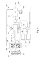
- Fig. 1 10 shows components of a rivet setting apparatus 30, and more particularly a pressing detector 94 according to an exemplary embodiment of the invention and a triggering mechanism 156 operatively coupled thereto for actuating the setting of a blind rivet 66 into two metal plates 62, 64 to be joined together.
- a plunger 10 is operatively connected to a striker 9 and can be accelerated by means of flywheels 13. If the plunger 10, starting from the in Fig. 1 shown operating state accelerates to the left, so meets an end 11 of the plunger 10 on a rear end face of the blind rivet 66, whereby this is driven into the metal plates 62, 64 to be fastened together.
- the flywheels 13 may be rotated by means of a drive motor 134, as illustrated by arrows 14.
- the flywheels 13 can (as in Fig. 1 shown) may be arranged at a distance from the impactor 9 and then do not act on the striker 9. However, the flywheels 13 can also be driven towards each other and accelerate when the impactor 9 is between them, the impactor 9 and consequently the plunger 10th
- the trigger mechanism 156 exactly two actuators or release buttons 5, namely a trigger actuator 58 and a fuse actuator 60. Both actuators 58, 60 are mechanically actuated by the hand of a user and can be configured as buttons or buttons or lever switching elements ,
- the drive motor 134 can be activated to drive the flywheels 13 and thus to provide drive energy for accelerating the ram 10.
- the trigger actuation element 58 must be actuated so that it acts on a first microswitch 122, which depending on the actuation time of the trigger actuation element 58, the drive motor 134 (an electric motor in the illustrated embodiment) selectively on or off.
- a second microswitch 124 a setting process can be triggered by actuation of the triggering actuating element 58, that is to say an action of the drive energy of the drive motor 134 on the striking member 9 and thus the tappet 10 is made possible.
- a trigger lock in the form of a mechanically acting locking member 126 to overcome, unlock or transfer to an unlocked. This is only as described below by a very specific concerted actuation of the trigger actuation element 58 and the safety actuation element 60 by a user. In total, a three-stage actuation process is to be executed by a user to trigger a setting process:
- the trigger actuator 58 is actuated so that the drive motor 134 is activated to provide electrical drive power for setting the blind rivet 66.
- the drive motor 134 and consequently the flywheels 13 are set in motion by operating the trigger actuator 58 for a period ⁇ t greater than a first threshold value T 1 .
- the first threshold T 1 may be 0.5 seconds.
- step (1) the securing operation member 60 is operated with the operation step (2).
- step (2) the locking member 126, which has previously prevented the triggering of the setting of the blind rivet 66, unlocked.
- step (3) the user-side performing a subsequent operation step (3) allows, which then the actual setting process can be triggered.
- step (3) By the actuating step (3) the flywheels 13, which have already been set in motion or in rotation, are moved toward one another or at least one is moved translationally in the direction of the other so that they can act laterally on the impactor 9 released for a movement, whereby the impactor body 9 according to Fig. 1 is accelerated to the left, whereby the plunger 10 in turn strikes the blind rivet 66 and thereby the setting of the blind rivet 66 is performed in the metal plates 62, 64 to be fastened to each other.
- T 2 3 s stop the drive motor 134 again or disconnect from its power supply.
- T 2 can also take other values.
- a shutdown takes place when no further operation takes place within a predetermined time window, for example 30 s.
- the described mechanism for initiating the setting process combines a high degree of safety with a user-friendly operating comfort and an energy-saving mode of operation. Because by the drive motor 134 early, i. already sufficiently long before the actual setting process, is set in motion, this can ramp up to operating speed over a relatively long period of time, since the actual setting even the release of the mechanical locking member 126 can be waited by a user. Thus, although the drive motor 134 is activated relatively early, peak load intervals during operation of the drive motor 134 can be avoided. As a result, total operating energy can be saved.
- the arrangement shown also shows the contact pressure detector 94.
- the contact pressure detector 94 By means of the contact pressure detector 94, it is detected whether the blind rivet 66 mounted on the rivet setting device 30 is properly pressed against the metal plates 62, 64 to be fastened to each other before setting.
- the contact pressure detector 94 has a contact pressure sensor 106 (for example a pressure or force sensor, which can be configured as a multi-layer sensor), which is set up to detect whether the blind rivet 66 is pressed against the metal plates 62, 64 with a sufficient contact pressure.
- the decision criterion may be whether the contact pressure exceeds a predefinable contact pressure threshold.
- Fig. 1 only partially shown setting device 30 on the muzzle side a Formmerkmalerkennungsflansch 118 which is shaped so that it allows the Anpresssensor 106 due to a mechanical shape recognition mechanism, the detection of the contact pressure only when the mounted on the Formmerkmalerkennungsflansch 118 blind rivet 66 fulfills a predetermined shape feature.
- the blind rivet 66 has an annular setting head 98, which can only press against the contact pressure sensor 106 and thus activate the contact pressure sensor 106 to generate a sensor signal when the setting head 98 on the one hand is large enough not to fall through the narrow right-hand central bore of the feature recognition flange 118 On the other hand, if the setting head 98 is small enough to be inserted into the left larger central opening of the feature recognition flange 118. This can ensure that only the shape characteristic fulfilling blind rivets 66 are processed with the Nietsetzêt 30. As a result, the reliability is further increased.
- the control unit 136 then activates the drive motor 134 (ie, is activated Engine in Fig. 8 acting on the spindle) provided that the actuators 58, 60 are operated simultaneously as described above.
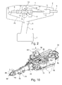
- Fig. 2 schematically shows a setting tool according to an exemplary embodiment of the invention, which has a housing 1.
- the housing 1 has a front end 2, in which a holder 3 is arranged for a bolt to be set or a blind rivet to be set.
- the housing 1 contains a handle 4, on which a user can attack.
- On the handle 4 is a shutter button 5 or more shutter buttons 5 are arranged, with the help of which the user can initiate a setting process and thus perform.
- From the front end 2 of the housing 1 protrudes a connected to the holder 3 nozzle 6, which is to be made against a substrate to which an attachment, is pressed to thereby overcome a trigger lock.
- a receptacle 7 for a power supply unit for example, an accumulator, a battery or a power adapter
- a second motor 18 serves to move the two flywheels 13 against each other such that they are delivered to the striker 9 out. This means that in the example shown, the upper of the two flywheels 13 is subjected to a translation in the direction of the impactor 9, so that subsequently the two flywheels 13 engage opposite surfaces of the impactor 9, which - when the first motor 8 the flywheels 13 rotational energy prepares - the setting process triggers.
- the second motor 18 is also used, in another operating state of the setting device, to deduct a residual mandrel from the blind rivet after retracting a blind rivet into sheet metal plates or the like and to withdraw it into the interior of the setting device.
- the second motor 18 may have an electric motor and act on a spindle driven thereby as the actual drive.
- the impactor 9 is under the influence of the flywheels 13 in the housing 1 along its own longitudinal direction movable and has at its front end to the plunger 10, the end 11 to hit the head of a Setzniets or bolt, which is attached to the bracket 3 and the nozzle 6 is mounted.
- the guide 12 passes between the two flywheels 13 therethrough.
- the flywheels 13 are by means of parallel, perpendicular to the plane of the Fig. 2 stored extending axes and are driven in the direction of arrows 14 by the motor 8 in opposite directions. Their distance from each other is matched to the impactor 9, that this, when it is arranged in a first position between the two flywheels 13, is touched by the surfaces of both flywheels 13. As a result, the flywheels 13 are able to convert their rotary motion into a linear movement of the impactor 9. The distance is further adapted to the impactor 9, that this, when it is arranged in a second position between the two flywheels 13, is spaced from the surfaces of the flywheels 13. A transfer of the setting device between the two positions accomplished the motor 18th
- a user presses the socket 6 with the bolt inserted against the target object and presses the release button (s) 5.
- the motor 8, see also Fig. 10 now drives the flywheels 13.
- the impactor 9 and the flywheels 13 are brought into operative connection by means of the motor 18, whereby the plunger 10 is accelerated in the direction of the bolt. Thereby, the plunger 10 exerts a driving force on the bolt, which is consequently driven into the target object.
- the striker 9 can be pushed back or withdrawn.
- a tension element 21 can serve, which is fastened, for example, at the rear end of the impactor 9 and, for reasons of saving space, is guided around the housing 1 by one and optionally a plurality of deflection rollers (s) 20. Again by means of the motor 18, the residual mandrel is pulled, which is then fully conveyed into the housing 1.
- Fig. 3 shows the Nietsetzêt 30 in a starting position. This initial position corresponds to an operating condition that is assumed after a blind rivet 66 (shown in FIG Fig. 4 ) into two metal plates 62, 64 (shown in FIG Fig. 4 ) has been driven. In this case, a front Blindnietteil remains with a positive locking head in the metal plates 62, 64 now attached to each other, wherein by means of retraction of a residual mandrel 32 of the blind rivet 66 after its driving into the metal plates 62, 64 at a predetermined breaking point 34 of
- Residual mandrel 32 is separated from the front Blindnietteil, whereby the blind rivet 66 is divided into two separate rivet parts.
- the residual mandrel 32 remains within the rivet setting device 30, as in FIG Fig. 3 shown.
- the predetermined breaking point 34 of the blind rivet 66 forms the transition between the in Fig. 3 Restdorn shown 32 and the already driven front Blindnietteil.
- the collet 36 has clamping jaws 38 for engaging the remaining mandrel 32, wherein corresponding profilings on abutting surfaces of the clamping jaws 38 on the one hand and the remaining mandrel 32 on the other hand for a safe provide mutual support.
- an Anpressdetektierech 46 can be detected whether a blind rivet 66 inserted into the holder 3 by a user against a target object, in particular a metal plate 62, 64, is pressed or not. For security reasons, only upon successful detection Such a pressing by means of the Anpressdetektierech 46 allows a subsequent setting process. If the rivet setting device 30 is pressed against a target object without inserted blind rivet 88, a safety sleeve 88 is not completely pressed on - there is a gap between a cover 90 and the safety sleeve 88.
- Fig. 3 further shows a return spring 92 for returning the safety sleeve 88 to a home position when a pressing is terminated. According to Fig. 3 but a contact on the safety sleeve 88 is interrupted, the solenoid 40 is in a locking position.
- the plunger 10 is according to Fig. 3 by means of an indicated with reference numeral 42 plunger lock, which may be formed as a latch mechanism secured. Furthermore, according to Fig. 3 the flywheels 13 in an open state. The associated flywheel drive is switched off.
- a tappet feed 52 is designed to guide the tappet 10 or the impact body 9 interacting with the tappet 10.
- Tension springs 54 are provided on the tappet feed 52, which can be tensioned during the later movement of a spindle 50 and relaxed during rivet driving in order to pre-accelerate the tappet 10 from engagement with the flywheels 13.
- the spindle 50 can be driven by means of a motor 18 (in particular an electric motor) in order to carry out a linear spindle movement for triggering a riveting operation.
- a speed selection switch 56 is user-operable to set a desired operating or target speed of the drive motor 8.
- Fig. 3 Incidentally, there is also a V-belt 55 of the driver 8.
- the rotational speed may be adjusted based on characteristics (for example, material, thickness, number) of the components to be connected to each other by a rivet connection, in the example shown, the metal plates 62, 64.
- a riveting rivet 66 can be inserted into the riveting setting device 30.
- Fig. 4 shows the rivet setting device 30 in an operating state in which the new blind rivet 66 has been inserted into socket 6, the remaining mandrel 32 has already been transferred to a collecting container and the rivet setting device 30 at two metal plates 62, 64 to be fastened together by forming a riveted joint as a target object for the blind rivet 66 is pressed.
- Trigger 5 is actuated (eg, tapped) by a user a first time to start rivet setting device 30, thereby causing flywheels 13 to move.
- the flywheels 13 are set to a user-side set speed in rotation. The displacement of the flywheels 13 in rotation thus takes place when the trigger 5 has been actuated for the first time, since this triggers the starting of the drive motor 8 for driving the flywheels 13.
- the contact in the pressing detection unit 46 is closed in operative connection with the safety sleeve 88, and the solenoid 40 outputs the lock or triggering mechanism 232 (FIG. Fig. 15 ) free.
- the safety sleeve 88 is pressed into the recess in the cover 90 when the rivet setting device 30 is pressed against the metal plates 62, 64.
- the Anpresstraction is closed and the solenoid 40 unlocks the trigger mechanism.
- the actual settlement can now be triggered via the trigger 5.
- the user operates after the first actuation of the trigger actuation element 58, the safety actuation element 60 and thereby unlocks a mechanical release lock, which has previously prevented the full pressing of the trigger actuation element 58. Only after this unlocking a further or further actuation of the trigger actuation element 58 is mechanically enabled, whereby it comes to triggering a Nietsetzvorgangs.
- a first phase of a spindle stroke of the spindle 50 is moved forward (ie in accordance with FIG Fig. 4 to the left), for which the motor 18 provides drive energy.
- This advancement of the spindle 50 causes, if by a previous Nachschieben a new blind rivet 66 of the remaining mandrel 32 has been advanced to the magnet holder, that the residual mandrel 32 is further pulled by magnets of the magnet holder into the magnet holder inside.
- the remaining mandrel 32 is disposed of in the mandrel disposal unit 44 in a third phase of the spindle stroke.
- the magnet holder during the spindle stroke, guided by a guided in turn in a slide guide 74 guide member 76 down and releases a Eintreibbahn along which then the plunger 10 can be moved to the newly inserted blind rivet 66 in the metal sheets 62, 64th collect.
- the slotted guide 74 has a guide recess in which the guide element 76 can be inserted, which in turn acts on the magnet holder.
- the guide member 76 is a body which can be guided in the slotted guide 74 and thereby activates or deactivates the forward movement of the plunger 10 by controlling the magnetic holder and on the other hand contributes to the residual mandrel disposal.
- the plunger 10 is then pre-accelerated by relaxing the tension springs 54. If the plunger 10 or its impact body 9 comes into the sphere of influence of the compressed flywheels 13, they accelerate the pre-accelerated plunger 10 to such a speed that the plunger 10 drives the new blind rivet 66 into the metal sheets 62, 64.
- Fig. 5 5 shows the rivet setting device 30 in an operating state in which the blind rivet 66 inserted into the holder 3 is driven into the metal plates 62, 64 to be joined by the end 11 of the ram 10 coming back onto the blind rivet 66.
- the rivet initiation is triggered by means of a triggering mechanism (see also FIG Fig. 11 ) or trigger 70.
- a triggering mechanism see also FIG Fig. 11
- trigger 70 As a result, the plunger 10 is released, and the driving operation is carried out.
- the flywheels 13 are again in an open state, ie, they no longer act on the ram 9.
- the plunger or the plunger feed 52 is then retracted back to the starting position.
- the retraction of the plunger 10 to the starting position is effected by means of the spring 54 (and by means of springs 228, 224, see, for example Fig. 15 ), carried out.
- An associated ram repeating system 72 is shown in FIG Fig. 9 designated by reference numeral 72.
- the ram repeating system 72 provides for returning the plunger 10 to the initial state after a riveting operation has been performed.
- the ram repeating system 72 includes the pulleys 20 and the tension member 21 which is attachable to the shock body 9 at one end and which is deflected over the pulleys 20 on the principle of a cable. By providing these pulleys 20, the ram repeating system 72 and consequently the entire riveting tool 30 can be made compact.
- Fig. 6 shows the Nietsetzêt 30 in a state in which the plunger 10 is braked and the residual energy of the plunger 10 is dissipated.
- This over-energy of the plunger 10 is reduced by means of a plunger brake 48, which is formed in the described embodiment as an elastomeric brake.
- the plunger brake 48 can receive kinetic energy of the plunger 10 when moving the plunger 10 for driving the blind rivet 66 and thus act as an attenuator.
- Fig. 7 shows how the Rietsetzêt 30 is postponed.
- the plunger 10 and the striking mass or the impactor 9 already repeated by the as a string (for example, an inelastic nylon cord or an elastomeric cord) trained tension element 21, ie according to Fig. 7 transported to the right, and secured at the respective starting position.
- a string for example, an inelastic nylon cord or an elastomeric cord
- Fig. 8 shows the rivet setting device 30 in forming a closing head.
- the spindle 50 moves back.
- the jaws 38 become wedged in a profiled portion of the blind rivet 66 such that the residual mandrel 32, ie, the rear portion of the blind rivet 66, is torn off by restoring movement from the remainder of the blind rivet 66 (remaining in the metal plates 62, 64).
- the residual mandrel 32 is thus pulled and formed the closing head.
- the mandrel break takes place at the predetermined breaking point 34.
- the rivet setting device 30 thus applies a Fig.
- FIGS. 7 and 8 show that in the final phase of the setting process, the guide element 76 is guided within a guide recess of the guide slot 74.
- the spindle 50 moves after the mandrel pulling back to the front to the starting position.
- the rivet setting device 30 is again in the in Fig. 3 shown starting position.
- Fig. 9 shows a three-dimensional view and individual assemblies of the rivet setting 30th
- a drive-in unit 78 which activates the driving of the blind rivet 66 into the components to be interconnected allows the above-mentioned and described in more detail below trigger mechanism.
- the plunger feed 52 and a rocker 80 with a spring assembly 82 are connected to the drive-in unit 78.
- the rocker 80 with the spring assembly 82 serves as a lever mechanism for opening and closing the flywheels 13 for space-saving transfer of force to the storage of the flywheels 13 to move them toward each other or move away from each other.
- a bias of at least one of the flywheels 13 against the plunger 10 ensures the exercise of a sufficiently high frictional force of the flywheel or wheels 13 on the plunger 10, wherein the degree of interaction can be adjusted by adjusting the frictional force.
- the mandrel removal unit 44 can be mounted on a mandrel tractor unit 84.
- the mandrel removal unit 44 is used to dispose of a residual mandrel 32 of a blind rivet 66, which remaining mandrel 32 is demolished during the setting process of the blind rivet 66 and remains within the rivet setting device 30. In this case, an undesirable jamming or tilting of the remaining mandrel 32 in a channel between a mounting location (where the blind rivet 66 is mounted before or for setting) and a residual mandrel receptacle (which can accommodate many remaining mandrels 32, which are then disposed of batchwise or in groups can) avoided.
- the channel is at least and preferably partially provided or lined with a frictional positive guide structure, in particular an elastomer hose, along which the residual mandrel 32 is moved by means of friction tight and without Ausweichnnenkeit along.
- a frictional positive guide structure in particular an elastomer hose
- the drive-in unit 78 and the mandrel unit 84 are loosely inserted into each other.
- After tilting the clamping lever the driving unit 78 is pulled over a housing in the direction Dornzugmaschine 84.
- the mandrel unit 84 is thereby pressed against the housing.
- the driving unit 78 and the mandrel unit 84 may alternatively be coupled together in other ways, for example by means of a screw connection.
- a controller 86 may include a processor that controls the rivet setting operation of the rivet setting device 30.
- the control unit 86 is executed in the embodiment shown as a control board.
- the ram repeating system 72 is based on an inelastic but flexible tension member 21 (in particular a cord) in combination with an in Fig. 9 not shown and separate, during setting process clamping energy receiving clamping element (in particular a tension spring).
- a low-wear ram repeating system 72 is provided for retrieving the plunger 10 after a setting operation in an initial position for preparing a subsequent further setting process.
- the inelastic but flexible tension member 21 has favorable sliding friction properties, whereas the tension member can effectively build a clamping force when the plunger 10 moves away from its initial position during the setting process. This allows the repetition of the mass of ram 10 and striker 9 over a large distance.
- an unintentional and dangerous triggering a setting process can be excluded by ensuring that the setting process is triggered only when the user deliberately actuates the trigger mechanism.
- the deliberate release operation is carried out according to the invention via two independent actuators 58, 60.
- a preferably mechanically acting release lock can be overcome.
- a locking member Separated from the trigger actuator 58 is a locking member which blocks the trigger actuator 58 until the backup actuator 60 is actuated. If the safety operating element 60 is not actuated, the user can start the drive motor by tapping the trigger actuation element 58. Release for starting the drive-in process takes place only when the safety actuation element 60 has been actuated and subsequently the trigger actuation element 58 is actuated once more.
- Fig. 10 shows a bottom view of the setting device 30 according to Fig. 3 to Fig. 9 , In the following, reference is made to Fig. 11 to Fig. 21 a trigger mechanism 232 of the setting device 30 described in more detail.
- Fig. 11 first shows the portion of the setting device 30, which forms the trigger mechanism 232.
- FIGS. 12 and 13 show the triggering mechanism 232 in a locked state.
- the rear of the plunger 10 arranged impactor 9 is held by means of a locking pawl 214.
- the locking pawl 214 engages in the locked state in a designated as a locking recess 212 groove in the striker 9 a.
- the spring-loaded latch pawl 214 is operatively coupled to a ram lock lever 222 which performs the function of the trip lock.
- the plunger locking lever 222 is locked as long as by a solenoid 40 as unlocking until the setting device 30 muzzle side, ie at the location of the inserted blind rivet 66, is pressed against metal sheets 62, 64 and thus a safety circuit is closed.
- the plunger locking lever 222 acts by means of a gate-guided lever mechanism with a release lever 208 to which a tension spring 228th is mounted, and with a clamping lever 220 together.
- Fig. 13 shows that the locking pawl 214 is biased by means of a coil spring as a pawl suspension 234 in the direction of the locking recess 212.
- FIGS. 14 and 15 show the triggering mechanism 232 in a first operating condition.
- the trigger mechanism Prior to actuation of a trigger actuation element 58, the trigger mechanism is in the in FIGS. 14 and 15 shown position.
- a plunger slide 236 is in a rearward position and is locked via the plunger locking lever 222, which also holds the plunger 10 and the striker 9 in the rearward position.
- the solenoid 40 locks the plunger locking lever 222 and thus prevents disengagement of the plunger 10 and the impactor 9.
- the release lever 208 is held with the tension spring 228 in the starting position.
- the clamping lever 220 is spring-loaded with a leg spring as a torsion spring 224 in the clockwise direction and is pressed against a stop 240.
- An attack angle is in Fig. 15 designated by reference numeral 238.
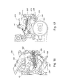
- FIGS. 16 and 17 show the triggering mechanism 232 in a second operating condition. If the riveting tool 30 is pressed correctly against metal sheets 62, 64 and the actuators 58, 60 are actuated, the drive spindle 50 (not shown in FIG FIGS. 16 and 17 ) moved forward.
- the solenoid 40 is actuated (when the setting tool is pressed with inserted blind rivet 66 against metal sheets 62, 64) and unlocks the plunger locking lever 222.
- the spindle 50 also drags the plunger slide 236 with. As a result, the compression springs 54 are compressed, which builds up bias.
- the trigger lever 208 which is rotatably mounted on this, is pulled under the stop angle 238 along. In this case, the tension lever 220 is rotated counterclockwise downwards over a curve on the trigger lever 208.
- the leg spring 224 is thus biased and pushes over the tensioning lever 220 the release lever 208 against the stop angle 238 upwards.
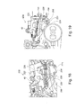
- FIGS. 18 and 19 show the triggering mechanism 232 in a third operating condition.
- the clamping lever 220 is biased to the maximum.
- the trigger lever 208 was pulled out from the stop angle 238.
- the leg spring 224 may now relax and urge the release lever 208 upward counterclockwise against the ram lock lever 222. If by this time the setting device 30 is still pressed, the plunger lock lever 222 is not locked by the solenoid 40 and thus can be pivoted, which releases the plunger 10 and the striker 9.
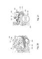
- FIGS. 20 and 21 show the triggering mechanism 232 in yet another mode of operation.
- the trigger lever 208 has been rotated by the torsion spring 224 via the tension lever 220 and has opened the plunger lock lever 222.
- the impactor 9 has been pushed between the flywheels 13.
- a carriage hook 242 disengages the plunger carriage 236, it is pulled to the right via the tension spring 228.
- the trigger lever 208 is pulled up over the stop bracket 238 until it reaches the home position again.
- a first blind rivet 66 is inserted into the mouth of the rivet setting device 30.
- the trigger actuator 58 is actuated for the first time to activate the motor 8 and bring the flywheels 13 into rotation and operating speed.
- the rivet setting device 30 is pressed with inserted blind rivet 66 to the metal sheets 62, 64 to control the solenoid 40 for releasing the locking of the plunger structure 9, 10 upon successful detection of pressing by the Anpressdetektiertechnik 46.
- the setting process is initiated by the plunger 10 impinges on the muzzle 66 used rivet and this drives into the metal sheets 62, 64. Excess energy of the plunger 10 is received by the plunger brake 48 made of an elastomeric material.
- the flywheels 13 are returned to an open state.
- the plunger structure 9, 10 is retracted by means of a ram repeating system 72 back to the starting position.
- a Dornzugrind is triggered, ie a retraction of the driven blind rivet 66 in the direction of the setting device 30, whereby a front piece of Blindniets 66 to form a closing head in the metal plates 62, 64 remains and this holds together form-fitting, whereas a residual mandrel 32 from the front Piece is demolished at the predetermined breaking point 34 and remains in the rivet setting device 30.
- Fig. 22 again shows the rivet setting device 30 according to Fig. 3 to Fig. 21 and a pressure detector 94 provided at the mouth side.
- Fig. 23 shows an enlarged view of the Anpressdetektors 94.
- the shape feature recognition device 118 has a lid 90 and a patch on it and in the non-pressing state through a gap 89 (see Fig. 24 ) separate safety sleeve 88. Only when exerting the contact pressure (and upon fulfillment of the predetermined shape feature) of a blind rivet 66, the safety sleeve 88 presses into the gap 89. This is in the operating state according to FIGS. 23 and 24 not the case.
- the Anpressdetektierritt 46 can detect that the blind rivet 66 is pressed against the metal plate 62 with a pressure exceeding the predetermined threshold.
- An enlarged view of the Anpressdetektiertechnik 46 in Fig. 24 shows that this has a decoupled from the safety sleeve 88 first contact element 142 and
- a second contact element 144 rigidly coupled to the safety sleeve 88.
- the first electrical contact element 142 and the second electrical contact element 144 are brought into contact with each other, since upon movement of the safety sleeve 88 this entrains the second electrical contact element 144.
- an electrical sensor signal is generated, which is indicative that the blind rivet 66 is pressed against the metal plate 62 with the contact pressure exceeding the predetermined threshold value.
- a biasing or restoring spring 92 configured as an annular spring is provided for predetermining the threshold value, which generates such a mechanical pretension that, in the non-pressing state, the gap 89 is maintained and after the elimination of a previously applied contact pressure, the gap 89 is again formed.
- the return spring 92 is annularly connected to one of the end face of the safety sleeve 88 opposite end portion of the safety sleeve 88.
- the lid 90 of the Anpressdetektors 94 is cup-shaped and includes a jacket-shaped, approximately hollow cylindrical portion and a perforated end face.
- the lid 90 is partially covered at the perforated end face of a ring portion of the safety sleeve 88, see Fig. 23 , Further, the lid 90 is spanned on the jacket of four mutually spaced by 90 ° strip-shaped sections of the safety sleeve 88.
- FIGS. 23 and 24 show the Anpressdetektor 94 in an operating condition in which no blind rivet 66 is mounted on the setting device 30. Show against it Fig. 25 to Fig. 27 a state in which such a blind rivet 66 is mounted to the setting device 30 ready to be set.
- a pressing of the safety sleeve 88 against the metal plate 62 can not allow triggering a sensor event, since due to the absence of a correctly assembled blind rivet 66, the shape feature is not met and thus the gap 89 can not be closed. As a result, the contact members 142 and 144 can not be brought into electrically conductive contact.
- Fig. 25 shows in a spatial view
- Fig. 26 shows in a cross-sectional view that now a blind rivet 66 is mounted mouth side.
- Fig. 27 shows how the inserted blind rivet 66 is pressed against the metal plate 62.
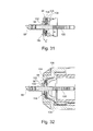
- FIGS. 28 to 32 show a pressure detector 94 according to another exemplary embodiment of the invention.
- FIG. 28 shown in an exploded view, in the disc-like or annular components of the Anpressdetektors 94 are shown separated from each other.
- a contact pressure sensor 106 of the contact pressure detector 94 designed as a multi-layer sensor has a plurality of thin-film rings 110, 112, 114, 116 which are flexibly connected to one another and which are in Fig. 29 are shown separated from each other.
- the thin-film rings 110, 112, 114, 116 are bonded to a laminate structure.
- the thin-film rings 110, 112, 114, 116 each have a central bore, through which a shaft part of a blind rivet 66 can be passed.
- the laminated state according to Fig. 28 For example, the laminate arrangement of the thin-film rings 110, 112, 114, 116 is compressed upon application of a contact pressure exerted by a setting head 98 of a blind rivet 66 on the laminate arrangement.
- two electrically conductive thin-film rings 110, 112 make electrical conductive contact with each other, thereby triggering a sensor signal which is transmitted via an electrically conductive conductor strip 154 Control unit (not shown) can be supplied.
- Control unit (not shown) can be supplied.
- the conductor strip 154 other electrically conductive connections can be provided.
- the conductor strip 154 has, as in Fig. 29 shown, two electrically conductive strips, one of which is connected to an associated one of the electrically conductive thin-film rings 110, 112. The two electrically conductive strips are separated from one another by means of an electrically insulating intermediate strip 160, which is connected to a spacer ring 116 of electrically insulating material.
- the spacer ring 116 made of an electrically insulating material separates the electrically conductive thin-film rings 110, 112. If the contact pressure does not exceed the predetermined threshold value, the spacer ring 116 holds the two electrically conductive thin-film rings 110, 112 spaced from each other. However, if the contact pressure exceeds the predetermined threshold, at least one of the two electrically conductive thin-film rings 110, 112 is deformed or pushed into or through holes in the spacer ring 116, whereby the electrically conductive thin-film rings 110, 112 come into contact with each other.
- a spring ring 114 is formed as a further thin-film ring and defines pressure points for the two thin-film rings 110, 112, when the shaft of the blind rivet 66 is passed through the thin-film rings 110, 112, 114, 116 and the setting head 98 on the thin-film rings 110, 112, 114, 116 presses.
- the spring ring 114 has two spring arms, which are both formed by an annular leaf spring 146. Each of the spring arms has a projection 148, with which a respective pressure point on the electrically conductive thin-film rings 110, 112 is defined.
- a plate spring 102 is provided with an annular collar 152.
- a thin film support ring or support plate 104 may be provided between the plate spring 102 and the multi-layer sensor 106.
- the plate spring 102 including ring-shaped collar 152 is recessed in a mouth opening of the setting device 30.
- the blind rivet 66 satisfies the predetermined shape feature
- the blind rivet 66 mounted on the feature recognition flange 118 presses on the annular collar 152 of the plate spring 102 upon application of the pressing pressure, thereby triggering a sensor signal.
- the shape feature recognition flange 118 has a cavity 138 defined by the inner diameter d of the annular collar 152, through which a too small rivet 66 passes when the contact pressure is applied, without being able to act on the contact pressure sensor 106.
- a projection 140 (limited inwardly by inner diameter D) is at an applied contact pressure too large rivet 66 on the outside, without being able to act on the Anpresssensor 106.
- a receiving groove 158 can, as in Fig. 30 shown, with applied contact pressure a matching rivet 66 (outer diameter L of the setting head 98) are taken in order to act on the Anpresssensor 106 can.
- Fig. 32 is an even larger view of the mouth area to see.
- the multilayer flexible printed circuit board described above, see Fig. 29 is constructed such that the lower conductive foil 110 and the upper conductive foil 112 join each other as soon as a defined force is applied to the spring plate 114.
- the spring plate 114 has a design which defines the pressure point on the conductive films 110, 112. Via the spacer ring 116, the conductive films 110, 112 separated from each other, and the adhesive film 150 allows attachment to the mouth 108.
- the various layers are all pressed together and glued together and form the multi-layer sensor 106th
- the support plate 104 and the plate spring 102 transmit the required contact force for switching the multi-layer sensor 106. It is pasted behind a dome and thus protected from excessive forces.
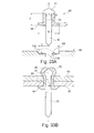
- FIG. 33A and 33B. 14 show different views of a blind rivet 66 according to an exemplary embodiment of the invention for cooperating with a pressure detector 94 for detecting the pressing of such a mating blind rivet 66.
- the in Fig. 33A Blind rivet 66 shown is configured to form a positive connection with a pressure detector 94, wherein a blind rivet 66 correctly recognized by the pressure detector 94, together with the presence of a sufficiently large contact pressure, is the prerequisite for a subsequent setting process to be triggered.
- a shaping feature 98 of the blind rivet 66 it is necessary for a shaping feature 98 of the blind rivet 66 to fit geometrically with respect to its size and to a shape feature recognition device 118 of the contact pressure detector (94). Then it is a contact pressure sensor 106 of the Anpressdetektors 94 allows to detect the detection of a contact pressure.
- the blind rivet 66 has a cylindrical rivet mandrel 32 (which can have an end tip) with a mandrel head 31 which has been widened at the end and a mechanically weakened predetermined breaking point 34 between the rivet mandrel 32 and the mandrel head 31. Furthermore, the blind rivet 66 has as a second component a sleeve-shaped rivet 33 with an end-side collar-like widening. Rivet mandrel 32 and rivet 33 are frictionally hidden with each other.
- the hollow rivet 33 encloses a central portion of the rivet mandrel 32 and has an annular setting head 98 at an end facing away from the mandrel head 31. The shape and size of the latter represents the abovementioned shape feature of the blind rivet 66.
- the annular setting head 98 has an outer diameter B in a range between 9.0 mm and 11.5 mm, in particular in a range between 9.1 mm and 9, 7 mm.
- the annular setting head 98 has an axial thickness a in a range between 0.8 mm and 1.2 mm, has an axial length A in a range between 8 mm and 20 mm and has an inner diameter b in a range between 2.5 mm and 3.5 mm.
- FIG. 33A schematically shows an end portion of the Anpressdetektors 94, which has a receiving groove 158 as a shape feature recognition device 118, which is adapted to the setting head 98 in terms of their dimensions.
- the receiving groove 158 has a relation to the setting head 98 inverse form.
- the receiving groove 158 has an outer diameter C in a range between 9.0 mm and 11.5 mm.
- a person skilled in the art will recognize that a technically conditioned play can be provided between the setting head 98 and the receiving groove 158, so that the setting head 98 can be inserted into the receiving groove 158 without jamming, for example by means of mere muscular force.
- the blind rivet 66 is inserted into the mouth of the Anpressdetektors 94. Fit in the sense of a positive connector cooperating and matched components in the form of Setting head 98 and receiving groove 158 in terms of size and shape together, so setting head 98 can dive into the receiving groove 158 positively and fill them substantially gap-free. A setting process with too large or too small or incorrectly shaped setting heads 98 of blind rivets 66 is impossible because with them a correct pressing can not be detected. If the blind rivet 66 is inserted properly into the mouth of the contact pressure detector 94, then the contact pressure sensor 106 can detect whether a contact pressure of the blind rivet 66 mounted ready for setting fulfills a predetermined criterion. If this is the case, the blind rivet 66 along an arrow in Fig. 33A into a target object, for example the two in Fig. 33B shown metal sheets 62, 64, are driven.
- a blind rivet 66 with an unusually large setting head 98 having an outer diameter B in a range between 9.0 mm and 11.5 mm has advantages.
- a use of foreign rivets can be made mechanically impossible, which increases the reliability.
Landscapes
- Engineering & Computer Science (AREA)
- Mechanical Engineering (AREA)
- Insertion Pins And Rivets (AREA)
- Portable Nailing Machines And Staplers (AREA)
- Measuring Fluid Pressure (AREA)
- Force Measurement Appropriate To Specific Purposes (AREA)
Abstract
Anpressdetektor (94) für eine Steckverbindung mit einem Befestigungselement (66) zum Detektieren des Anpressens eines Setzgeräts (30) mit daran montiertem Befestigungselement (66) gegen ein Zielobjekt (62, 64), in welches das Befestigungselement (66) zu setzen ist, wobei der Anpressdetektor (94) einen Anpresssensor (46; 106), der eingerichtet ist zu erkennen, ob das Befestigungselement (66) mit einem Anpressdruck gegen das Zielobjekt (62, 64) gedrückt wird, welcher Anpressdruck einen vorgegebenen Schwellwert überschreitet, und eine Formmerkmalerkennungseinrichtung (118) aufweist, die eingerichtet ist, dem Anpresssensor (46; 106) das Erkennen des Anpressdrucks nur dann zu ermöglichen, wenn das an der Formmerkmalerkennungseinrichtung (118) montierte Befestigungselement (66) ein vorgegebenes Formmerkmal erfüllt.An abutment detector (94) for a connector comprising a fastener (66) for detecting the pressing of a fastener (30) having a fastener (66) mounted thereon against a target (62, 64) into which the fastener (66) is to be seated the contact pressure detector (94) has a contact pressure sensor (46; 106) which is set up to detect whether the fastening element (66) is pressed against the target object (62, 64) with a contact pressure, which contact pressure exceeds a predefined threshold value, and a shape feature recognition device ( 118), which is set up to enable the contact pressure sensor (46; 106) to recognize the contact pressure only when the fastening element (66) mounted on the shape feature recognition device (118) fulfills a predetermined shape feature.
Description
Die Erfindung betrifft einen Anpressdetektor zum Detektieren des Anpressens eines Setzgeräts mit einem schussbereiten Befestigungselement gegen ein Zielobjekt, ein Setzgerät, ein Befestigungselement, eine Setzanordnung und ein Verfahren zum Setzen eines Befestigungselements in ein Zielobjekt mittels eines Setzgeräts.The invention relates to an Anpressdetektor for detecting the pressing of a setting device with a ready-shot fastener against a target, a setting device, a fastener, a setting arrangement and a method for setting a fastener in a target by means of a setting device.
Zum Setzen von Befestigungselementen wie Nägel, Bolzen oder dergleichen ist es bekannt, Geräte zu verwenden, in denen ein Stößel ruckartig vorwärtsgetrieben wird, der an dem Befestigungselement angreift und dieses in den Untergrund eintreibt. Damit der Stößel einen für das Eintreiben des Befestigungselements ausreichenden Impuls übertragen kann, soll er einerseits auf eine hohe Geschwindigkeit beschleunigt werden und andererseits mit einer ausreichend großen Masse versehen oder verbunden sein. Um die hohe Geschwindigkeit zu erreichen, sind unterschiedliche Antriebsarten bekannt, beispielsweise explosionsbetriebene Geräte, in denen eine Treibladung gezündet wird. Ebenfalls bekannt sind Geräte, bei denen eine rotierende Schwungmasse mit dem Stößel über eine Kupplung verbunden ist. Bei allen Arten von Antrieben muss der Stößel wieder in seine Ausgangsposition zurückbewegt werden, um dann einen nächsten Befestigungsvorgang durchführen zu können. Diese Rückwärtsbewegung kann durch mechanische Verbindungen, bei explosionsbetriebenen Geräten durch Umlenken eines Teils der Antriebsgase, oder manuell von Hand verwirklicht werden. Beim Betrieb eines solchen Setzgeräts ist also ein hohes Maß an Betriebssicherheit erforderlich.For setting fasteners such as nails, bolts or the like, it is known to use devices in which a plunger is driven forward jerky, which acts on the fastener and this drives into the ground. So that the plunger can transmit a sufficient for the driving of the fastener pulse, it should be accelerated on the one hand to a high speed and on the other hand provided with a sufficiently large mass or connected. To achieve the high speed, different types of drives are known, for example, explosion-powered devices in which a propellant charge is ignited. Also known are devices in which a rotating flywheel is connected to the plunger via a coupling. For all types of drives, the plunger must be moved back to its original position, in order then to carry out a next fastening operation can. This backward movement can be realized by mechanical connections, in explosion-powered devices by diverting a portion of the drive gases, or manually by hand. When operating such a setting device so a high degree of operational safety is required.
Es ist eine Aufgabe der vorliegenden Erfindung, ein weiter verbessertes System zum Setzen eines Befestigungselements bereitzustellen.It is an object of the present invention to provide a further improved fastener placement system.
Diese Aufgabe wird durch die Gegenstände mit den Merkmalen gemäß den unabhängigen Patentansprüchen gelöst. Weitere Ausführungsbeispiele sind in den abhängigen Ansprüchen gezeigt.This object is solved by the objects with the features according to the independent claims. Further embodiments are shown in the dependent claims.
Gemäß einem Ausführungsbeispiel der vorliegenden Erfindung ist ein Anpressdetektor für eine Steckverbindung mit einem Befestigungselement zum Detektieren des Anpressens eines Setzgeräts mit einem setzbereit eingesetzten Befestigungselement gegen ein Zielobjekt, in welches das Befestigungselement zu setzen ist, geschaffen, wobei der Anpressdetektor einen Anpresssensor, der eingerichtet ist zu erkennen, ob das Befestigungselement mit einem Anpressdruck gegen das Zielobjekt gedrückt wird, welcher Anpressdruck einen vorgegebenen Schwellwert überschreitet, und eine Formmerkmalerkennungseinrichtung aufweist, die eingerichtet ist, dem Anpresssensor das Erkennen des Anpressdrucks nur dann zu ermöglichen, wenn das an der Formmerkmalerkennungseinrichtung montierte Befestigungselement ein (insbesondere durch die Formgebung der Formmerkmalerkennungseinrichtung) vorgegebenes Formmerkmal erfüllt. Gemäß einem weiteren Ausführungsbeispiel der vorliegenden Erfindung ist ein Befestigungselement für eine Steckverbindung (insbesondere gemäß einem Schlüssel-Schloss-Prinzip) mit einem Anpressdetektor, insbesondere mit einem Anpressdetektor mit den oben beschriebenen Merkmalen, zum Detektieren des Anpressens eines Setzgeräts mit dem setzbereiten Befestigungselement gegen ein Zielobjekt, in welches das Befestigungselement zu setzen ist, geschaffen, wobei das Befestigungselement ein Formmerkmal (insbesondere eine Form und Größe eines in eine Mündung des Anpressdetektors einzuführenden Abschnitts des Befestigungselements) aufweist, das zum Zusammenwirken mit einer Formmerkmalerkennungseinrichtung (insbesondere eine Mündung des Anpressdetektors mit einer Form und einer Größe, welche spezifisch auf die Aufnahme des einzuführenden Abschnitts des Befestigungselements angepasst sind; insbesondere können Formmerkmal und Formmerkmalerkennungseinrichtung die gleiche Größe und eine zueinander inverse Form aufweisen) des Anpressdetektors derart eingerichtet ist, dass einem Anpresssensor des Anpressdetektors das Erkennen eines Anpressdrucks dadurch (insbesondere nur dadurch) ermöglicht ist, dass das an der Formmerkmalerkennungseinrichtung montierte Befestigungselement das Formmerkmal aufweist.According to an exemplary embodiment of the present invention, there is provided a press-on detector for a plug-in connection with a fastening element for detecting the pressing of a setting device with a fastener that is ready for insertion against a target object into which the fastening element is to be set, wherein the contact pressure sensor is adapted to a contact pressure sensor recognize whether the fastening element is pressed against the target object with a contact pressure, which contact pressure exceeds a predetermined threshold value, and has a shape feature recognition device which is configured to enable the contact pressure sensor to recognize the contact pressure only if the fastening element mounted on the shape feature recognition device ( in particular by the shape of the feature recognition device) predetermined feature met. According to a further embodiment of the present invention is a fastener for a connector (in particular according to a key-lock principle) with a Anpressdetektor, in particular with a Anpressdetektor with the features described above, for detecting the pressing of a setting device with the settable fastener against a target object in which the fastening element is to be set created, wherein the fastening element has a shape feature (in particular a shape and size of a to be introduced into an orifice of the Anpressdetektors portion of the fastener), which cooperate with a shape feature recognition device (in particular an orifice of the Anpressdetektors with a shape and a size, which are specifically adapted to the receptacle of the inserted portion of the fastener; in particular, shape feature and shape feature recognition means the same size and ei ne to each other inverse shape) of the Anpressdetektors is set up such that a contact pressure of the Anpressdetektors the detection of a contact pressure thereby (in particular only by) is made possible that at the Form feature recognition device mounted fastener having the shape feature.
Gemäß einem weiteren Ausführungsbeispiel der vorliegenden Erfindung ist ein Setzgerät, insbesondere ein Nietsetzgerät, zum Setzen eines Befestigungselements bereitgestellt, wobei das Setzgerät einen Anpressdetektor mit den oben beschriebenen Merkmalen zum Detektieren des Anpressens des Setzgeräts mit einem setzbereiten Befestigungselement gegen ein Zielobjekt, in welches das Befestigungselement zu setzen ist, und eine Antriebseinheit zum Antreiben eines beweglichen Stößels zum Einwirken auf das Befestigungselement zum Setzen des Befestigungselements in das Zielobjekt aufweist, wobei das Setzgerät eingerichtet ist, die Antriebseinheit erst dann zum Auslösen des Setzens des Befestigungselements aktivieren zu lassen, wenn der Anpressdetektor das Anpressen mit dem den vorgegebenen Schwellwert überschreitenden Anpressdruck detektiert hat.According to a further exemplary embodiment of the present invention, a setting device, in particular a rivet setting device, is provided for setting a fastening element, wherein the setting device has a pressure detector with the features described above for detecting the pressing of the setting device with a settable fastening element against a target object, into which the fastening element set, and a drive unit for driving a movable plunger for acting on the fastener for setting the fastener into the target object, wherein the setting device is configured to activate the drive unit to trigger the setting of the fastener only when the Anpressdetektor pressing has detected with the predetermined threshold exceeding contact pressure.
Gemäß einem weiteren Ausführungsbeispiel der vorliegenden Erfindung ist eine Setzanordnung bereitgestellt, die ein Setzgerät mit den oben beschriebenen Merkmalen zum Setzen eines Befestigungselements und das Befestigungselement aufweist, das insbesondere setzbereit an oder in dem Setzgerät montiert sein kann.According to a further exemplary embodiment of the present invention, a setting arrangement is provided, which has a setting device with the above-described features for setting a fastening element and the fastening element, which in particular can be mounted ready for setting on or in the setting tool.
Gemäß einem weiteren Ausführungsbeispiel der vorliegenden Erfindung ist ein Verfahren zum Setzen eines Befestigungselements in ein Zielobjekt mittels eines Setzgeräts bereitgestellt, wobei bei dem Verfahren erkannt wird, ob das Befestigungselement, das an dem Setzgerät setzbereit montiert ist, mit einem Anpressdruck gegen das Zielobjekt gedrückt wird, der einen vorgegebenen Schwellwert überschreitet, wobei das Erkennen des Anpressdrucks nur dann ermöglicht wird, wenn das an dem Setzgerät montierte Befestigungselement ein vorgegebenes Formmerkmal erfüllt. Das Aktivieren einer Antriebseinheit zum Setzen des Befestigungselements wird vorteilhaft erst dann freigegeben , wenn erkannt worden ist, dass der Anpressdruck den vorgegebenen Schwellwert überschreitet.According to a further exemplary embodiment of the present invention, a method is provided for setting a fastening element into a target object by means of a setting device, wherein in the method it is detected whether the fastening element, which is mounted ready to be mounted on the setting tool, is pressed against the target object with a contact pressure, exceeds a predetermined threshold, wherein the detection of the contact pressure is only possible if the mounted on the setting device fastener meets a predetermined shape feature. The activation of a drive unit for setting the fastening element is advantageously only released when it has been recognized that the contact pressure exceeds the predetermined threshold value.
Erfindungsgemäß ist das Auslösen eines Setzprozesses zum Setzen eines Befestigungselements, wie einem Niet, mit hoher Betriebssicherheit ermöglicht. Dies wird erreicht, da erst bei ordnungsgemäßem Andrücken eines mittels eines Formfaktorabgleichs nach dem Schlüssel-Schloss-Prinzip korrekt identifizierten, an dem Setzgerät setzbereit montierten Befestigungselements, das mit einer definierten Anpresskraft gegen ein Zielobjekt gedrückt wird, das Auslösen des Setzprozesses ermöglicht wird. Durch diese Anpressdetektion kann ein unbeabsichtigtes Auslösen des Setzprozesses durch einen Benutzer oder ein Auslösen des Setzprozesses ohne Richten des Setzgeräts auf das Zielobjekt unterbunden werden. Ferner kann garantiert werden, dass nur bei Verwenden eines passenden Befestigungselements, welches das Formkriterium erfüllt, das für die Druckdetektion Voraussetzung ist, der Setzprozess ausgelöst werden kann. Ein sicher betreibbares und gleichzeitig benutzerfreundlich bedienbares Setzgerät kann damit fehlerrobust realisiert werden.According to the invention, the triggering of a setting process for setting a fastener, such as a rivet, allows high reliability. This is achieved because only when properly pressing a correctly identified by means of a Formfaktorabgleichs after the key-lock principle, on the setting tool mounted ready mounted fastener that is pressed with a defined contact force against a target object, the triggering of the setting process is made possible. By this Anpressdetektion an unintentional triggering of the setting process by a user or a triggering of the setting process can be prevented without directing the setting device to the target object. Furthermore, it can be guaranteed that the setting process can be triggered only when using a suitable fastening element, which fulfills the form criterion, which is a prerequisite for the pressure detection. A safely operable and at the same time user-friendly operating setting device can thus be realized in a robust manner.
Ein Nietsetzgerät, welches Niete hochdynamisch eintreibt, muss strengen Sicherheitsanforderungen genügen. Dabei darf kein Nietvorgang ausgelöst werden, solange der Anwender das Setzgerät nicht gegen eine Anwendung oder ein Zielobjekt presst. Dass dies erfüllt ist, stellt ein Sensor sicher, welcher zum Beispiel elektrisch den Nietsetzprozess startet, wenn der Anpressdruck durch das Sensordesign vorgebbare Anforderungen erfüllt. Gleichzeitig ist der Detektor so gestaltet, dass kein falscher Niet mit dem Setzgerät verarbeitet werden kann. Zu große bzw. zu kleine Setzkopfdurchmesser werden vom Gerät nicht erkannt und somit nicht freigegeben.A riveting tool, which drives rivets highly dynamically, must meet strict safety requirements. No riveting operation may be initiated unless the user presses the setting tool against an application or a target object. That this is fulfilled, a sensor ensures, for example, which electrically starts the Nietsetzprozess when the contact pressure by the sensor design meets specified requirements. At the same time the detector is designed so that no wrong rivet can be processed with the setting tool. Too large or too small setting head diameter are not recognized by the device and thus not released.
Anschaulich bilden erfindungsgemäß die Formmerkmalerkennungseinrichtung des Anpressdetektors einerseits und das Formmerkmal des Befestigungselements andererseits ein speziell aufeinander angepasstes Verbindungssystem aus zwei interagierenden Komponenten, die im Wege einer Steckverbindung, ähnlich wie ein Schlüssel und ein Schloss, sicherstellen, dass kein ungeeigneter Blindniet (oder ein anderes Befestigungselement) mit dem Setzgerät verwendet werden kann. Da aufgrund der erfindungsgemäßen Konzeption des Setzgeräts zum Teil eine wesentlich größere Eintreibgeschwindigkeit deren erreicht werden kann als mit herkömmlichen Setzgeräten, ist eine größere Aufschlagfläche, die mit einem Blindniet mit einer gegenüber herkömmlichen Blindnieten vergrößertem Setzkopf einhergehen, besonders vorteilhaft. Zudem führt das Verwenden von Blindnieten mit vergrößertem Setzkopf im gesetzten Zustand zu einem optisch ansprechenderen Erscheinungsbild und einer ebeneren Oberfläche der mittels solcher Befestigungselemente verbundenen Metallblechen oder dergleichen.Illustratively, according to the invention, the shape feature recognition device of the contact pressure detector on the one hand and the shape feature of the fastener on the other hand form a specially adapted connection system of two interacting components, the way a plug connection, similar to a key and a lock, ensure that no unsuitable blind rivet (or other fastener) can be used with the setting tool. Since due to the inventive design of the setting device in part a much greater Eintreibgeschwindigkeit can be achieved than with conventional setting tools, a larger impact surface, which is associated with a blind rivet with a comparison with conventional blind rivets increased setting head, particularly advantageous. In addition, the use of blind rivets with increased setting head in the set state to a visually appealing appearance and a more planar surface of the connected by means of such fasteners metal sheets or the like.
Im Weiteren werden zusätzliche exemplarische Ausführungsbeispiele des Anpressdetektors, des Setzgeräts, der Setzanordnung und des Verfahrens beschrieben.Hereinafter, additional exemplary embodiments of the Anpressdetektors, the setting device, the setting arrangement and the method will be described.
Gemäß einem Ausführungsbeispiel kann die Formmerkmalerkennungseinrichtung als vorgegebenes Formmerkmal überprüfen, ob eine geometrische Größe des Befestigungselements oder einer Komponente davon innerhalb eines Bereichs zwischen einer vorgegebenen Mindestgröße und einer vorgegebenen Maximalgröße liegt. Ausschließlich Niete mit einem Wert für die geometrische Größe innerhalb dieses Intervalls werden vom Gerät verarbeitet, da ansonsten das Auslösen eines Setzprozesses verunmöglicht wird. Die Formmerkmalerkennungseinrichtung kann somit eine Formkodierung des Befestigungselements überprüfen und somit sicherstellen, dass nur technisch und sicherheitsbezogen korrekte Befestigungselemente verarbeitet werden können.According to one embodiment, the shape feature recognition device can check as a given shape feature whether a geometric size of the fastener or a component thereof is within a range between a predetermined minimum size and a predetermined maximum size. Only rivets with a value for the geometric size within this interval are processed by the device, otherwise it will not be possible to trigger a setting process. The shape feature recognition device can thus check a shape coding of the fastener and thus ensure that only technically and safety-related correct fasteners can be processed.
Gemäß einem Ausführungsbeispiel kann die Formmerkmalerkennungseinrichtung einen Formmerkmalerkennungsflansch aufweisen, der einen Hohlraum aufweist, durch den bei angelegtem Anpressdruck ein zu kleines Befestigungselement hindurchtritt, ohne auf den Anpresssensor einwirken zu können, und einen Vorsprung aufweist, an dem bei angelegtem Anpressdruck ein zu großes Befestigungselement anliegt, ohne auf den Anpresssensor einwirken zu können. Wenn das Befestigungselement zu klein ist, d.h. aus diesem Grund das geforderte Formmerkmal nicht erfüllt, wird verhindert, dass das eingesetzte Befestigungselement auf den Anpresssensor einwirken kann, da es durch ein Zentralloch des Anpresssensors hindurch fällt. Andererseits kann, wenn das Befestigungsmittel zu groß ist und das geforderte Formmerkmal aus diesem Grund nicht erfüllt ist, das Befestigungselement bei Ansetzen an der Formmerkmalerkennungseinrichtung an dem Vorsprung anstoßen bzw. aufliegen, ohne mechanischen Kontakt zu dem Anpresssensor zu erlangen. Somit kann sowohl hinsichtlich zu großer als auch hinsichtlich zu kleiner Befestigungselemente eine Formselektion durchgeführt werden.According to one exemplary embodiment, the shape feature recognition device may have a shape feature recognition flange which has a cavity through which a too small fastening element passes without an impact on the contact pressure sensor, and has a projection against which an excessively large fastening element is applied when contact pressure is applied, without being able to act on the contact pressure sensor. If the fastener is too small, that is, for this reason, does not meet the required shape feature, prevents the fastener used can act on the Anpresssensor, as it by a Central hole of the Anpresssensors falls through. On the other hand, if the fastener is too large and the required shape feature is not met for this reason, the fastener abut when applying to the shape feature recognition device on the projection or rest, without gaining mechanical contact with the Anpresssensor. Thus, both in terms of too large and in terms of too small fasteners a shape selection can be performed.
Gemäß einem Ausführungsbeispiel kann der Formmerkmalerkennungsflansch zudem eine Aufnahmenut (die zwischen Vorsprung und Hohlraum angeordnet sein kann) aufweisen, in der bei angelegtem Anpressdruck ein passendes (d.h. passend geformtes und passend großes) Befestigungselement zumindest teilweise derart aufgenommen ist, um auf den Anpresssensor einwirken zu können. In einer mechanischen Analogie dient die Aufnahmenut als Schlüsselloch und das Befestigungselement als Schlüssel, um den Anpresssensor zum Detektieren zugänglich zu machen. Dadurch kann sichergestellt werden, dass bei dem Nietsetzgerät nur passende Niete eingesetzt werden, womit die Betriebssicherheit erhöht ist.According to one exemplary embodiment, the shape feature recognition flange can also have a receiving groove (which can be arranged between the projection and the cavity), in which a fitting (ie suitably shaped and suitably large) fastening element is at least partially received in such a manner in order to be able to act on the contact pressure sensor , In a mechanical analogy, the receiving groove serves as a keyhole and the fastener as a key to make the contact pressure sensor accessible for detection. In this way it can be ensured that only suitable rivets are used in the rivet setting device, whereby the operational safety is increased.
Die Aufnahmenut kann einen Außendurchmesser in einem Bereich zwischen ungefähr 9,0 mm und ungefähr 11,5 mm haben. Insbesondere kann die Aufnahmenut im Rahmen eines technisch bedingten Spiels den gleichen Außendurchmesser aufweisen wie ein Setzkopf eines aufzunehmenden Blindniets. Anders ausgedrückt kann der Schaltbereich des Anpressdetektors so bemessen sein, dass ein Blindniet nur dann akzeptiert wird, wenn sein Außendurchmesser zwischen ungefähr 9,0 mm und ungefähr 11,5 mm beträgt. Da andernfalls das Formmerkmal nicht erfüllt ist, wird ein solcher Niet kein ausreichend starkes Anpressen an den Anpressdetektor ermöglichen, was eine Voraussetzung für die Freigabe des Setzvorgangs ist.The receiving groove may have an outer diameter in a range between about 9.0 mm and about 11.5 mm. In particular, the receiving groove in the context of a technical game can have the same outer diameter as a setting head of a male blind rivet. In other words, the switching range of the contact pressure detector may be such that a blind rivet is accepted only if its outer diameter is between about 9.0 mm and about 11.5 mm. Otherwise, the shape feature is not met, such a rivet will not allow a sufficiently strong pressing against the Anpressdetektor, which is a prerequisite for the release of the setting process.
Gemäß einem Ausführungsbeispiel kann der Anpresssensor als elektrischer Kontaktsensor bzw. ohmscher Kontaktsensor (d.h. als Kontaktsensor, der das Herstellen eines direkten, elektrisch leitenden Kontakts zwischen zwei elektrisch leitfähigen Kontaktelementen als Sensorereignis erkennt) ausgebildet sein, der dann, wenn der Anpressdruck den vorgegebenen Schwellwert überschreitet, das Ereignis des Vorliegens eines elektrischen bzw. ohmschen Kontakts zwischen Kontaktelementen elektrisch erkennt, welche Kontaktelemente unterhalb des vorgegebenen Schwellwert voneinander kontaktfrei beabstandet sind. Mit einem solchen ohmschen Kontaktsensor ist es möglich, eine quasi digitale Aussage "Kontakt ja/nein" zu erhalten, was mit hoher Fehlerrobustheit und selbst bei Vorliegen von Störsignalen zuverlässig möglich ist. Alternativ zu einem ohmschen Kontaktsensor kann aber zum Beispiel auch ein kapazitiver Kontaktsensor eingesetzt werden, der bei Änderung eines Abstands zwischen zwei Kondensatorplatten eine veränderte Kapazität und somit veränderte elektrische Eigenschaften erkennt.According to one embodiment, the contact pressure sensor may be an electrical contact sensor or ohmic contact sensor (ie, a contact sensor which makes it possible to establish a direct, electrically conductive contact between two electrical contacts conductive contact elements as a sensor event detects), which, when the contact pressure exceeds the predetermined threshold value, the event of the presence of an electrical or ohmic contact between contact elements electrically detects which contact elements are spaced below the predetermined threshold from each other without contact. With such an ohmic contact sensor, it is possible to obtain a quasi-digital statement "contact yes / no", which is reliably possible with high error robustness and even in the presence of interference signals. As an alternative to an ohmic contact sensor, however, it is also possible, for example, to use a capacitive contact sensor which recognizes a changed capacitance and thus changed electrical properties when a distance between two capacitor plates is changed.
Gemäß einem Ausführungsbeispiel kann der Anpresssensor mehrere miteinander flexibel verbundene Dünnschichtringe aufweisen, insbesondere ausgebildet als eine Laminatstruktur. Durch die Dünnschichtringe ist ein Abschnitt des Befestigungselements hindurchführbar. Die Dünnschichtringe werden, wenn der Anpressdruck eines anderen Abschnitts des Befestigungselements den vorgegebenen Schwellwert beim Andrücken überschreitet, derart komprimiert, dass zwei der Dünnschichtringe (die als "Kontaktdünnschichtringe" bezeichnet werden können), die zuvor kontaktfrei voneinander beabstandet waren, miteinander in elektrischen Kontakt geraten. Ein solcher mehrlagiger Aufbau zu einem Sensor ist hochkompakt. Die Dünnschichtringe können Ringe sein, die einen Durchmesser haben, der mindestens einen Faktor 10 größer als eine Dünnschichtringdicke ist. Ferner kann ein solcher Dünnschichtring eine zentrale Öffnung aufweisen, wobei die Öffnungen oder Zentralbohrungen der miteinander zu einer Laminatstruktur verbundenen Dünnschichtringe fluchten können, um eine gemeinsame Durchtrittsöffnung für das Befestigungselement zu bilden. Eine solche Laminatstruktur kann durch Verkleben oder sonstiges Verbinden der einzelnen Dünnschichtringe erhalten werden und bildet eine Flachstruktur. Bei den flexibel verbundenen Dünnschichtringen handelt es sich um eine Anordnung, die bei Ausüben eines äußeren Drucks die Relativposition zwischen den einzelnen Dünnschichtringen ändern kann, womit das Sensorereignis ausgelöst wird. Insbesondere kann dies dadurch erfolgen, dass zwei zunächst galvanisch getrennte elektrisch leitfähige Dünnschichtringe kontaktiert werden, wenn der Anpressdruck den Schwellwert überschreitet. Dann fließt ein elektrischer Strom zwischen diesen Kontaktdünnschichtringen, wenn zwischen ihnen eine elektrische Spannung angelegt wird. Die Anordnung aus Dünnschichtringen bildet einen miniaturisierten Sensor, der auch bei engsten Platzverhältnissen zuverlässig das Ausüben des geforderten Anpressdrucks detektieren kann.According to one embodiment, the contact pressure sensor may have a plurality of thin-film rings flexibly connected to one another, in particular formed as a laminate structure. Through the thin-film rings, a portion of the fastener can be passed. The thin-film rings, when the contact pressure of another portion of the fastener exceeds the predetermined pressure threshold, are compressed such that two of the thin-film rings (which may be referred to as "contact thin-film rings") which were previously spaced contact-free, come into electrical contact with each other. Such a multilayer structure to a sensor is highly compact. The thin film rings may be rings having a diameter that is at least a factor of 10 greater than a thin film ring thickness. Furthermore, such a thin-film ring can have a central opening, wherein the openings or central bores of the thin-film rings connected to one another to form a laminate structure can be aligned in order to form a common passage opening for the fastening element. Such a laminate structure can be obtained by gluing or otherwise bonding the individual thin-film rings and forms a flat structure. The flexibly connected thin-film rings are an arrangement which, when exerting an external pressure, can change the relative position between the individual thin-film rings, thereby triggering the sensor event. In particular, this can be done by contacting two initially electrically isolated thin-film rings when the contact pressure exceeds the threshold value. Then, an electric current flows between these contact thin film rings when an electric voltage is applied therebetween. The arrangement of thin-film rings forms a miniaturized sensor that can reliably detect the application of the required contact pressure even in the tightest of spaces.
Mit einer solchen Dünnschichtstruktur ist anschaulich ein Mikroschalter zur Anpressdetektion eines Setzgeräts bereitgestellt. In Übereinstimmung mit der Beschaffenheit eines Niets ist der Sensor sehr kurz baubar. Um möglichst kurze Nietdorne und letztendlich ein kurzes Setzgerät zu erhalten, besteht zwischen Setzkopf und Setzgerät nur ein begrenzter Bauraum. Trotz kompakter Bauweise ist der Sensor aber gegen die hohen Kräfte geschützt, welche bei der Schließkopfbildung herrschen. Die beschriebene Dünnschichtarchitektur erfüllt diese Anforderungen.With such a thin-film structure, a microswitch for pressing detection of a setting device is illustratively provided. In accordance with the nature of a rivet, the sensor is very short buildable. In order to obtain the shortest possible mandrels and ultimately a short setting tool, there is only a limited space between the setting head and the setting tool. Despite its compact design, the sensor is protected against the high forces that prevail during closing head formation. The described thin-film architecture fulfills these requirements.
Gemäß einem Ausführungsbeispiel können die zwei Dünnschichtringe aus einen elektrisch leitfähigen Material gebildet sein und erst dann, wenn der Anpressdruck den vorgegebenen Schwellwert überschreitet, miteinander in ohmschen Kontakt geraten. Wird eine Spannung zwischen den beiden Dünnschichtringen angelegt, so kann erst bei Überschreiten des vorgegebenen Schwellwerts ein Stromfluss zwischen diesen erfasst werden, was als Sensorereignis interpretiert werden kann.According to one exemplary embodiment, the two thin-film rings may be formed from an electrically conductive material and only come into ohmic contact with one another when the contact pressure exceeds the predetermined threshold value. If a voltage is applied between the two thin-film rings, then a current flow between them can only be detected when the predetermined threshold value is exceeded, which can be interpreted as a sensor event.
Gemäß einem Ausführungsbeispiel kann zwischen den zwei Dünnschichtringen ein Durchgangslöcher aufweisender Distanzring (der auch als "Distanzdünnschichtring" bezeichnet werden kann) aus einem elektrisch isolierenden Material vorgesehen sein, der, wenn der Anpressdruck den vorgegebenen Schwellwert nicht überschreitet, die zwei Kontaktdünnschichtringe voneinander beabstandet hält. Anschaulich kann ein solcher Distanzdünnschichtring durch eine Anzahl von Kreisringsegmenten ausgebildet werden, welche durch einen oder mehrere sich radial erstreckende Verbindungsstreifen miteinander mechanisch verbunden sein können. Wird der Anpressdruck über den vorgegebenen Schwellwert erhöht, so wird in einem oder mehreren der Durchgangslöcher ein elektrisch leitfähiger Kontakt zwischen den zuvor beabstandeten elektrisch leitfähigen Kontaktdünnschichtringen ausgeübt, womit das Sensorereignis erfasst werden kann. Ein gelochter Distanzring hat sich als zuverlässig erwiesen, einerseits bei kleinen Erschütterungen oder Krafteinwirkungen ein falsches Sensorereignis auszuschließen und andererseits bei Überschreitung des Anpressdrucks das Bereitstellen eines Sensorereignisses zuverlässig zu erkennen.According to one embodiment, a spacer ring (which may also be referred to as a "spacer thin film") may be provided between the two thin film rings of an electrically insulating material which, when the contact pressure does not exceed the predetermined threshold, keeps the two contact film rings spaced from each other. Illustratively, such Spacer layer ring can be formed by a number of circular ring segments, which can be mechanically connected to each other by one or more radially extending connecting strips. If the contact pressure is increased above the predetermined threshold value, an electrically conductive contact is exerted in one or more of the through holes between the previously spaced-apart electrically conductive contact thin-film rings, with which the sensor event can be detected. A perforated spacer ring has proven to be reliable, on the one hand exclude a false sensor event with small shocks or force effects and on the other hand to reliably detect the provision of a sensor event when exceeding the contact pressure.
Gemäß einem Ausführungsbeispiel kann ein anderer der Dünnschichtringe ein Federring (der auch als "Federdünnschichtring" bezeichnet werden kann) sein, der ausgebildet ist, mindestens einen Druckpunkt auf die zwei Kontaktdünnschichtringe zu definieren, wenn der Abschnitt des Befestigungselements durch die Dünnschichtringe hindurchgeführt und der andere Abschnitt des Befestigungselements auf die Dünnschichtringe einwirkt. Ein solcher Federdünnschichtring kann zum Beispiel aus Blech oder Stahl ausgebildet sein und Federeigenschaften, d.h. eine hookesche Rückstellcharakteristik, aufweisen. Der Federdünnschichtring kann ausgebildet sein, genau zu definieren, auf welche Weise ein Anpressdruck auf die beiden elektrisch leitfähigen Kontaktdünnschichtringe übertragen werden kann. Dadurch ist eine reproduzierbare Sensoranordnung erreicht, da die Krafteinleitung auf die beiden Kontaktdünnschichtringe in wohldefinierter Weise erfolgt.In one embodiment, another of the thin film rings may be a spring ring (which may also be referred to as a "spring thin film ring") configured to define at least one pressure point on the two contact film layers when the portion of the fastener passes through the thin film rings and the other portion of the fastener acts on the thin-film rings. Such a spring thin film ring may be formed of sheet metal or steel, for example, and has spring properties, i. a Hooke reset characteristic. The spring thin-film ring can be designed to define exactly how a contact pressure can be transmitted to the two electrically conductive contact thin-film rings. As a result, a reproducible sensor arrangement is achieved, since the force is applied to the two contact thin-film rings in a well-defined manner.
Gemäß einem Ausführungsbeispiel kann der Federdünnschichtring Federarme aufweisen, von denen jeder durch mindestens eine kreisringausschnittförmige Blattfeder gebildet ist, wobei jeder der Federarme einen Vorsprung hat, mit dem ein jeweiliger Druckpunkt auf die zwei Kontaktdünnschichtringe definiert ist. Somit kann der Federdünnschichtring als eine Anordnung von Kreisringen, insbesondere konzentrischen Kreisringen, angeordnet sein, die über einen oder mehrere radial verlaufende Materialstreifen miteinander verbunden sind. Die Vorsprünge können zum Beispiel Punktkontakte sein. Der Federdünnschichtring kann dann die auf ihn ausgeübte Kraft auf die elektrisch leitfähigen Kontaktdünnschichtringe an den Stellen der Vorsprünge weiterleiten.According to one embodiment, the spring thin-film ring can comprise spring arms, each of which is formed by at least one annular leaf-shaped leaf spring, each of the spring arms having a projection with which a respective pressure point is defined on the two contact thin-film rings. Thus, the spring thin-film ring can be arranged as an arrangement of circular rings, in particular concentric circular rings, which via one or a plurality of radially extending strips of material are interconnected. The projections may be, for example, point contacts. The spring thin-film ring can then forward the force exerted on it to the electrically conductive contact thin-film rings at the locations of the projections.
Gemäß einem Ausführungsbeispiel können die miteinander flexibel verbundenen Dünnschichtringe eine Adhäsionsschicht aufweisen, an der sie an einer Mündung des Setzgeräts befestigbar sind. Eine solche Klebeschicht erlaubt es, die Laminatstruktur aus den Dünnschichtringen an der Mündung des Setzgeräts zu befestigen, womit ein unerwünschtes Ablösen zuverlässig vermieden ist. Andere Befestigungen, zum Beispiel mit einer magnetischen Befestigungskraft, sind aber ebenfalls möglich.According to one exemplary embodiment, the thin-film rings connected to one another flexibly can have an adhesion layer, to which they can be fastened to an opening of the setting device. Such an adhesive layer makes it possible to attach the laminate structure of the thin-film rings at the mouth of the setting device, whereby unwanted detachment is reliably avoided. Other attachments, for example, with a magnetic fastening force, but are also possible.
Gemäß einem Ausführungsbeispiel kann die Formmerkmalerkennungseinrichtung eine Tellerfeder mit einem ringförmigen Kragen aufweisen, die derart in einer Mündungsöffnung des Setzgeräts versenkt anordbar oder angeordnet ist, dass, wenn das Befestigungselement das vorgegebene Formmerkmal erfüllt, das an der Formmerkmalerkennungseinrichtung montierte Befestigungselement bei Ausüben des Anpressdrucks auf den ringförmigen Kragen drückt. Der ringförmige Kragen kann im Querschnitt als Viertelkreiskrümmung aus einer ringförmigen, insbesondere kreisringförmigen, Tellerfeder herauswachsen und somit in Richtung des zu montierenden Befestigungselements aus der Sensoranordnung hervorragen. Ein Durchmesser der verbleibenden Zentralöffnung der Tellerfeder definiert dann die Mindestgröße, die ein Befestigungselement im Querschnitt haben muss, um das Formmerkmal zu erfüllen und folglich die Sensoranordnung erreichen zu können.According to one embodiment, the shape feature recognition device may comprise a plate spring with an annular collar, which can be arranged buried or arranged sunk in a mouth opening of the setting device, that when the fastening element fulfills the predetermined shape feature, the mounted on the shape feature recognition device fastener when applying the contact pressure on the annular Collar presses. The annular collar can outgrow in cross-section as a quarter circle of an annular, in particular annular, plate spring and thus protrude in the direction of the fastener to be mounted from the sensor assembly. A diameter of the remaining central opening of the cup spring then defines the minimum size that a fastener must have in cross section in order to meet the shape feature and thus to reach the sensor assembly can.
Gemäß einem Ausführungsbeispiel kann der Anpressdetektor einen Dünnschichtstützring zwischen der Tellerfeder und den miteinander flexibel verbundenen Dünnschichtringen aufweisen. Der Dünnschichtstützring kann zum Beispiel ein Metallring sein, welcher einen stabilen Zwischenring zwischen Tellerfeder und der Laminatstruktur bildet, um eine definierte Krafteinleitung zu unterstützen.According to an exemplary embodiment, the contact pressure detector may have a thin-film support ring between the disk spring and the thin-film rings connected to one another in a flexible manner. The thin-film support ring may be, for example, a metal ring, which forms a stable intermediate ring between the plate spring and the laminate structure in order to support a defined introduction of force.
Gemäß einem Ausführungsbeispiel können die mehreren miteinander flexibel verbundenen Dünnschichtringe, die Tellerfeder und optional (d.h. falls vorhanden) der Dünnschichtstützring gemeinsam eine Dicke in einem Bereich zwischen ungefähr 0.5 mm und ungefähr 3 mm haben. Ein Durchmesser kann in einem Bereich zwischen ungefähr 5 mm und ungefähr 30 mm liegen. Dadurch ist eine geringe Baugröße des Mikroschalters (zum Beispiel Durchmesser x Dicke gleich 15 mm x 1 mm) erreichbar. Insgesamt kann die Anordnung aus Dünnschichtringen und Tellerfeder einen Dünnschichtträger bilden, der flach auf eine Mündung des Setzgeräts aufgesetzt werden kann.According to an embodiment, the plurality of thin-film rings flexibly connected together, the plate spring and optionally (i.e., if present) the thin-film support ring may together have a thickness in a range between about 0.5 mm and about 3 mm. A diameter may range between about 5 mm and about 30 mm. As a result, a small size of the microswitch (for example, diameter x thickness equal to 15 mm x 1 mm) can be achieved. Overall, the arrangement of thin-film rings and disc spring can form a thin-film carrier, which can be placed flat on an opening of the setting device.
Gemäß einem anderen Ausführungsbeispiel kann die Formmerkmalerkennungseinrichtung einen Deckel und eine darauf aufgesetzte und davon im anpressfreien Zustand durch einen Spalt derart getrennte Sicherheitshülse aufweisen, dass bei Ausüben des Anpressdrucks und bei Erfüllung des vorgegebenen Formmerkmals das Befestigungselement die Sicherheitshülse in den Spalt drückt und dadurch den Anpresssensor erkennen lässt, dass ein geeignetes Befestigungselement mit einem den vorgegebenen Schwellwert überschreitenden Anpressdruck gegen das Zielobjekt gedrückt wird. Nur wenn die Geometrie des Befestigungselements es erlaubt, bei Ausüben eines Anpressdrucks den Spalt zwischen Deckel und Sicherheitshülse zu verringern bzw. zu schließen, kommt es durch die damit einhergehende Verschiebung der Sicherheitshülse relativ zu dem Deckel zu einem Sensorereignis.According to another embodiment, the shape feature recognition device may have a cover and a patch in the non-pressing state through a gap such a separate safety sleeve that when applying the contact pressure and fulfillment of the predetermined shape feature, the fastener pushes the safety sleeve into the gap and thereby recognize the Anpresssensor allows a suitable fastener is pressed against the target object with a contact pressure exceeding the predetermined threshold value. Only if the geometry of the fastener allows to reduce or close the gap between the cover and the safety sleeve when exerting a contact pressure, it comes through the concomitant displacement of the safety sleeve relative to the lid to a sensor event.
Gemäß einem Ausführungsbeispiel kann der Anpresssensor ein von der Sicherheitshülse entkoppeltes erstes Kontaktelement aufweisen und ein mit der Sicherheitshülse gekoppeltes zweites Kontaktelement aufweisen, wobei bei Drücken der Sicherheitshülse in den Spalt das erste Kontaktelement und das zweite Kontaktelement in Kontakt gebracht werden, womit erkannt wird, dass das Befestigungselement mit dem den vorgegebenen Schwellwert überschreitenden Anpressdruck gegen das Zielobjekt gedrückt wird. Die beiden Kontaktelemente können ohmsche bzw. elektrische Kontaktelemente sein, die quasi digital ein Signal erzeugen können, welches Aufschluss darüber gibt, ob oder ob nicht der Anpressdruck den Schwellwert überschreitet.According to one embodiment, the Anpresssensor may have a decoupled from the safety sleeve first contact element and having a coupled with the safety sleeve second contact element, wherein upon pressing the safety sleeve in the gap, the first contact element and the second contact element are brought into contact, which is recognized that the Fastening element is pressed with the predetermined threshold exceeding contact pressure against the target object. The two contact elements may be ohmic or electrical contact elements, the digitally able to generate a signal that provides information about whether or not the contact pressure exceeds the threshold value.
Gemäß einem Ausführungsbeispiel kann der Anpresssensor ein Vorspannelement zum Vorgeben des Schwellwerts aufweisen, das zum Erzeugen einer derartigen mechanischen Vorspannung eingerichtet ist, dass im anpressfreien Zustand der Spalt aufrechterhalten bleibt und nach Wegfall eines zuvor ausgeübten Anpressdrucks der Spalt wieder ausgebildet wird. Das Vorspannelement kann somit die Sicherheitshülse immer wieder in einen zu dem Deckel beabstandeten Zustand zurückzustellen, so dass nach einem Sensorereignis die Anordnung sofort wieder bereit ist, ein neues Sensorereignis zu detektieren.According to one embodiment, the contact pressure sensor may have a biasing element for specifying the threshold value, which is set up to generate such a mechanical bias, that the gap is maintained in the contact-free state and the gap is formed again after the elimination of a previously applied contact pressure. The biasing element can thus reset the safety sleeve repeatedly in a state spaced from the lid, so that after a sensor event, the arrangement is immediately ready to detect a new sensor event.
Gemäß einem Ausführungsbeispiel kann sich das Vorspannelement als Ringfeder an einen einer Stirnseite der Sicherheitshülse gegenüberliegenden Endabschnitt der Sicherheitshülse anschließen. Somit kann umfänglich an der Mündung des Setzgeräts ein Sensorereignis und eine rückstellende Kraft sichergestellt werden. Gemäß einem Ausführungsbeispiel kann der Deckel becherförmig mit einem Mantel und einer gelochten Stirnfläche ausgebildet sein. Der Deckel kann an der gelochten Stirnseite von einem Ringabschnitt der Sicherheitshülse teilweise überdeckt sein (wobei vorzugsweise die Lochung des Deckels mit einer Lochung des Ringabschnitts fluchtet, so dass ein Abschnitt des Befestigungselements durch die übereinander liegenden Lochungen hindurchführbar ist). Der Deckel kann an dem Mantel von voneinander beabstandeten streifenförmigen Abschnitten der Sicherheitshülse überspannt sein. Die Lochung der Stirnfläche und des Ringabschnitts erlauben einem Befestigungselement, an bzw. in einer solchen Anordnung montiert zu werden. Das Überspannen des Deckels mittels der Sicherheitshülse kann eine wohl definierte Ausgangsposition festlegen. Gemäß einem Ausführungsbeispiel kann eine Steuereinheit vorgesehen sein, die ein benutzerseitiges Auslösen des Setzens des Befestigungselements in das Zielobjekt mittels der Antriebseinheit freigibt, wenn der Anpressdetektor das geeignete Anpressen detektiert hat. Eine solche Steuereinheit kann zum Beispiel ein Prozessor (CPU oder Mikroprozessor) sein, der ein elektrisches Sensorsignal als Voraussetzung dafür verwendet, einen Setzvorgang freizugeben.According to one embodiment, the biasing element may connect as an annular spring to an end face of the safety sleeve opposite an end portion of the safety sleeve. Thus, a sensor event and a restoring force can be ensured circumferentially at the mouth of the setting device. According to one embodiment, the lid may be cup-shaped with a jacket and a perforated end face. The lid may be partially covered on the perforated end face by a ring portion of the safety sleeve (wherein preferably the perforation of the lid is aligned with a perforation of the ring portion, so that a portion of the fastener can be passed through the superposed perforations). The cover may be spanned on the jacket by spaced-apart strip-shaped sections of the safety sleeve. The perforation of the end face and the ring portion allow a fastener to be mounted on or in such an arrangement. The overstretching of the lid by means of the safety sleeve can define a well-defined starting position. According to one embodiment, a control unit may be provided which releases a user-side triggering of the setting of the fastening element in the target object by means of the drive unit, when the Anpressdetektor has detected the appropriate pressing. Such a control unit can, for example a processor (CPU or microprocessor) that uses an electrical sensor signal as a prerequisite to enable a set operation.
Gemäß einem Ausführungsbeispiel kann das Setzgerät einen benutzerseitig betätigbaren Auslösemechanismus aufweisen. Dieser kann derart eingerichtet sein, dass mittels Betätigens eines Abzugsbetätigungselements eine Versorgung der Antriebseinheit mit Antriebsenergie aktivierbar ist (zum Beispiel ein Antriebsmotor eingeschaltet wird, der die Schwungräder in Bewegung setzt), mittels Betätigens eines Sicherungsbetätigungselements eine Auslösesperre, die das Auslösen des Setzens des Befestigungselements mittels nochmaligen Betätigens des Abzugsbetätigungselements vor Entsperren der Auslösesperre sperrt, entsperrbar ist, und mittels nochmaligen Betätigens des Abzugsbetätigungselements nach Entsperren der Auslösesperre das Setzen des Befestigungselements auslösbar ist. Dadurch ist das Auslösen eines Setzprozesses zum Setzen eines Befestigungselements, wie eines Niets, mit hoher Sicherheit und gleichzeitig hohem Bedienkomfort ermöglicht, wobei simultan bei kurzer Setzzeit ein energiesparender Betrieb des oft als Handgerät ausgebildeten Setzgeräts ermöglicht ist. Die hohe Sicherheit ist erreichbar, indem das Auslösen des Setzprozesses nur ermöglicht wird, wenn ein Benutzer vor dem Auslösen mittels des Abzugsbetätigungselements eine Abzugssperre durch Betätigen des Sicherungsbetätigungselements betätigt hat, womit ein unbeabsichtigtes Auslösen unterbunden ist. Der hohe Bedienkomfort ist dadurch erreicht, dass die kombinatorische Betätigung von Abzugsbetätigungselement und Sicherungsbetätigungselement in äußerst intuitiver Weise an dem Setzgerät implementiert ist. Indem ferner das Starten der Antriebseinheit bereits bei einer zeitlich vorgelagerten ersten Betätigung des Abzugsbetätigungselements erfolgt, ist die Setzzeit kurz, da der Antriebsmotor bereits in Gang gesetzt worden ist, wenn der Setzprozess ausgelöst wird. Durch das zeitlich vorgelagerte Starten des Antriebsmotors sind an diesem in energiesparender Weise Spitzenbelastungen einer zugehörigen Energieversorgungseinheit (insbesondere eines Akkumulators) vermieden, da der Antriebsmotor nun langsamer hochfahrbar ist, ohne dass sich dadurch die Setzzeit verlängern würde, da vor der Ermöglichung des Auslösens des Setzens benutzerseitig ja noch die Sicherheitssperre zu überwinden ist.According to one embodiment, the setting device may have a user-actuated trigger mechanism. This can be set up in such a way that a supply of the drive unit can be activated by driving a trigger actuating element (for example a drive motor is switched on, which sets the flywheels in motion), by means of actuation of a securing actuating element a triggering lock which activates the setting of the fastening element again pressing the trigger actuating element before unlocking the trigger lock locks, is unlocked, and by pressing the trigger actuation element after unlocking the trigger lock setting the fastener is triggered. This allows the triggering of a setting process for setting a fastening element, such as a rivet, with high security and at the same time a high level of operating convenience, with simultaneous energy-saving operation of the setting device, which is often designed as a hand-held device, being possible with a short setting time. The high level of security can be achieved by triggering the setting process is only possible when a user has triggered a trigger lock by pressing the fuse actuating element before triggering by means of the trigger actuation element, whereby an unintentional triggering is prevented. The high ease of use is achieved in that the combinational actuation of trigger actuator and safety actuator is implemented in an extremely intuitive manner to the setting device. Furthermore, since the starting of the drive unit already takes place during a first actuation of the triggering actuating element upstream in time, the setting time is short, since the drive motor has already been set in motion when the setting process is triggered. Due to the temporally upstream starting of the drive motor peak loads of an associated power supply unit (in particular of a battery) are avoided in this energy-saving manner, since the drive motor is now slower hochfahrbar without thereby prolonging the setting time, since before enabling the triggering of the setting, the security barrier must still be overcome by the user.
Der Sensor kann ferner mit einem Überlastschutz versehen sein. Ein solcher Überlastschutz vermeidet eine Zerstörung des Sensors, wenn eine zu große Kraft angelegt wird.The sensor may further be provided with an overload protection. Such overload protection avoids destruction of the sensor if too much force is applied.
Gemäß einem Ausführungsbeispiel kann das Befestigungselement als Blindniet ausgebildet sein und einen Nietdorn mit einem Dornkopf und einer Sollbruchstelle zwischen Nietdorn und Dornkopf sowie einen Hohlniet aufweisen, der einen zentralen Abschnitt des Nietdorns umschließt und an einem von dem Dornkopf abgewandten Ende einen ringförmigen Setzkopf aufweist. Der ringförmige Setzkopf kann dann strukturell auf eine Aufnahmenut des Anpressdetektors angepasst sein, um nach dem Schlüssel-Schloss-Prinzip ein Ansprechen des Anpressdetektors zu ermöglichen.According to one embodiment, the fastening element may be designed as a blind rivet and have a rivet mandrel with a mandrel head and a predetermined breaking point between rivet mandrel and mandrel head and a hollow rivet, which surrounds a central portion of the rivet mandrel and at an end remote from the mandrel head has an annular setting head. The annular setting head can then be structurally adapted to a receiving groove of the Anpressdetektors to allow for the key-lock principle, a response of the Anpressdetektors.
Insbesondere kann der ringförmige Setzkopf einen Außendurchmesser in einem Bereich zwischen ungefähr 9,0 mm und ungefähr 11,5 mm, insbesondere in einem Bereich zwischen ungefähr 9,1 mm und ungefähr 9,7 mm, aufweisen. Anzumerken ist, dass ein derartiger Blindniet einem größeren Setzkopfdurchmesser aufweist als dies nach den einschlägigen Normen der Fall ist (vergleiche zum Beispiel DIN EN ISO 15979 oder ISO 15983). Da erfindungsgemäß aus Sicherheitsgründen ein zuverlässiges Zusammenpassen zwischen Befestigungselement und Anpressdetektor garantiert werden soll, kann durch die genannte Maßnahme zuverlässig ausgeschlossen werden, dass ungeeignete, herkömmliche Blindniete mit dem Gerät verwendet werden.In particular, the annular setting head may have an outer diameter in a range between about 9.0 mm and about 11.5 mm, in particular in a range between about 9.1 mm and about 9.7 mm. It should be noted that such a blind rivet has a larger setting head diameter than is the case according to the relevant standards (compare, for example, DIN EN ISO 15979 or ISO 15983). Since, for safety reasons, a reliable matching between the fastening element and the pressure detector is to be guaranteed according to the invention, it can be reliably ruled out by said measure that unsuitable, conventional blind rivets are used with the device.
Im Folgenden werden exemplarische Ausführungsbeispiele der vorliegenden Erfindung mit Verweis auf die folgenden Figuren detailliert beschrieben.
-
Fig. 1 zeigt einen Anpressdetektor zum Detektieren des Anpressens eines Setzgeräts mit daran montiertem Befestigungselement gegen ein Zielobjekt gemäß einem exemplarischen Ausführungsbeispiel der Erfindung. -
Fig. 2 zeigt schematisch einen Schnitt durch ein Setzgerät gemäß einem exemplarischen Ausführungsbeispiel der Erfindung. -
Fig. 3 bis Fig. 8 zeigen Querschnittsansichten eines Setzgeräts gemäß einem exemplarischen Ausführungsbeispiel der Erfindung in unterschiedlichen Betriebszuständen. -
Fig. 9 zeigt eine räumliche oberseitige Ansicht des Setzgeräts gemäßFig. 3 bis -
Fig. 8 und eine Ansicht von einzelnen Baugruppen dieses Setzgeräts. -
Fig. 10 zeigt eine räumliche, unterseitige Ansicht des Setzgeräts 30 gemäßFig. 3 bis Fig. 9 . -
Fig. 11 bis Fig. 21 zeigen einen Auslösemechanismus eines Nietsetzgeräts gemäß einem exemplarischen Ausführungsbeispiel der Erfindung. -
Fig. 22 bis Fig. 27 zeigen unterschiedliche Ansichten eines Anpressdetektors zum Detektieren des Anpressens eines Niets mittels des Setzgeräts ausFig. 3 bis Fig. 21 gemäß einem exemplarischen Ausführungsbeispiel der Erfindung in einem Betriebszustand ohne eingesetztem Niet (Fig. 23 und Fig. 24 ) bzw. mit eingesetztem Niet (Fig. 25 bis Fig. 27 ). -
Fig. 28 bis Fig. 32 zeigen unterschiedliche Ansichten eines Anpressdetektors zum Detektieren des Anpressens eines Niets mittels eines Setzgeräts gemäß einem anderen exemplarischen Ausführungsbeispiel der Erfindung. -
Fig. 33A und Fig. 33B zeigen unterschiedliche Ansichten eines Blindniets gemäß einem exemplarischen Ausführungsbeispiel der Erfindung zum Zusammenwirken mit einem Anpressdetektor zum Detektieren des Anpressens eines solchen passenden Blindniets.
-
Fig. 1 shows a Anpressdetektor for detecting the pressing of a setting device mounted thereon fastener against a target object according to an exemplary embodiment of the invention. -
Fig. 2 schematically shows a section through a setting tool according to an exemplary embodiment of the invention. -
Fig. 3 to Fig. 8 show cross-sectional views of a setting device according to an exemplary embodiment of the invention in different operating conditions. -
Fig. 9 shows a spatial top-side view of the setting device according toFig. 3 to -
Fig. 8 and a view of individual assemblies of this setting device. -
Fig. 10 shows a spatial, underside view of thesetting device 30 according toFig. 3 to Fig. 9 , -
Fig. 11 to Fig. 21 show a triggering mechanism of a rivet setting device according to an exemplary embodiment of the invention. -
FIGS. 22 to 27 show different views of a Anpressdetektors for detecting the pressing of a rivet by means of the setting deviceFig. 3 to Fig. 21 according to an exemplary embodiment of the invention in an operating state without rivet inserted (FIGS. 23 and 24 ) or with inserted rivet (Fig. 25 to Fig. 27 ). -
FIGS. 28 to 32 show different views of a pressure detector for detecting the pressing of a rivet by means of a setting device according to another exemplary embodiment of the invention. -
FIGS. 33A and 33B show different views of a blind rivet according to an exemplary embodiment of the invention for cooperation with a Anpressdetektor for detecting the pressing of such a matching blind rivet.
Gleiche oder ähnliche Komponenten in unterschiedlichen Figuren sind mit gleichen Bezugsziffern versehen.The same or similar components in different figures are provided with the same reference numerals.
Ein Stößel 10 ist mit einem Schlagkörper 9 wirkverbunden und kann mit Hilfe von Schwungrädern 13 beschleunigt werden. Wird der Stößel 10 ausgehend von dem in
Wie in
Durch Betätigen des Abzugsbetätigungselements 58 kann der Antriebsmotor 134 zum Antreiben der Schwungräder 13 und damit zum Bereitstellen von Antriebsenergie zum Beschleunigen des Stößels 10 aktiviert werden. Hierfür muss das Abzugsbetätigungselement 58 betätigt werden, so dass es auf einen ersten Mikroschalter 122 einwirkt, der abhängig von der Betätigungszeit des Abzugsbetätigungselements 58 den Antriebsmotor 134 (im gezeigten Ausführungsbeispiel ein Elektromotor) selektiv ein- oder ausschalten kann. Mittels eines zweiten Mikroschalters 124 kann durch Betätigen des Abzugsbetätigungselements 58 ein Setzvorgang ausgelöst werden, d.h. dass ein Einwirken der Antriebsenergie des Antriebsmotors 134 auf den Schlagkörper 9 und somit den Stößel 10 ermöglicht wird. Um das Auslösen des Setzvorgangs zu ermöglichen, ist aber zuvor eine Auslösesperre in Form eines mechanisch wirkenden Sperrglieds 126 zu überwinden, zu entsperren bzw. in einen Entsperrzustand überzuführen. Dies ist, wie im Weiteren beschrieben wird, nur durch ein ganz bestimmtes, konzertiertes Betätigen des Abzugsbetätigungselements 58 und des Sicherungsbetätigungselements 60 durch einen Benutzer möglich. Insgesamt ist zum Auslösen eines Setzvorgangs ein dreistufiger Betätigungsprozess von einem Benutzer auszuführen:By actuating the
In einem ersten Betätigungsschritt, der in
In einem in
Dies bedeutet, dass mittels nochmaligen Betätigens des Abzugsbetätigungselements 58 nach dem Entsperren der Auslösesperre in Form des Sperrglieds 126 durch Durchführen von Schritt (2) das Setzen des Blindniets 66 ermöglicht wird. Durch den Betätigungsschritt (3) werden die zuvor bereits in Schwung oder Rotation versetzten Schwungräder 13 aufeinander zu bewegt bzw. wird mindestens eines translatorisch in Richtung des anderen bewegt, so dass diese seitlich auf den für eine Bewegung freigegebenen Schlagkörper 9 einwirken können, womit der Schlagkörper 9 gemäß
Hat ein Benutzer durch Durchführen des Betätigungsschritts (1) den Antriebsmotor 134 in Bewegung versetzt, möchte der Benutzer einen Setzvorgang nun aber doch nicht durchführen oder das Setzgerät 30 wieder ausschalten, so kann der Benutzer durch nochmaliges Betätigen des Abzugsbetätigungselements 58 ohne gleichzeitiges Betätigen des Sicherungsbetätigungselements 60 für einen Zeitraum Δt > T2 = 3 s den Antriebsmotor 134 wieder stoppen bzw. von seiner Energieversorgung trennen. T2 kann auch andere Werte annehmen. Ferner erfolgt eine Abschaltung, wenn keine weitere Betätigung innerhalb eines vorgegebenen Zeitfensters erfolgt, beispielsweise 30 s.If a user has set the
Durch den beschriebenen Mechanismus zum Auslösen des Setzprozesses ist ein hohes Maß von Sicherheit mit einem benutzerfreundlichen Bedienkomfort und einer energiesparenden Betriebsweise kombiniert. Denn indem der Antriebsmotor 134 frühzeitig, d.h. schon ausreichend lange vor dem eigentlichen Setzvorgang, in Bewegung versetzt wird, kann dieser über einen relativ langen Zeitraum auf Betriebsdrehzahl hochfahren, da bis zum eigentlichen Setzen ja noch die Entriegelung des mechanischen Sperrglieds 126 durch einen Benutzer abgewartet werden kann. Obwohl also schon relativ frühzeitig der Antriebsmotor 134 aktiviert wird, können Spitzenlastintervalle beim Betrieb des Antriebsmotors 134 vermieden werden. Dadurch kann insgesamt Betriebsenergie eingespart werden.The described mechanism for initiating the setting process combines a high degree of safety with a user-friendly operating comfort and an energy-saving mode of operation. Because by the
Die in
Ferner weist das in
Erkennt der Anpresssensor 94, dass der Blindniet 66 mit einer ausreichend großen Kraft gegen die Metallplatten 62, 64 angepresst wird, so meldet er ein Signal an einen Prozessor bzw. eine Steuereinheit 136. Die Steuereinheit 136 aktiviert dann den Antriebsmotor 134 (d.h. aktiviert wird der Motor in
Das in
Ein erster Motor 8 dient dazu, zwei Schwungräder 13 in Rotation zu versetzen. Wirken die inRotation versetzten Schwungräder 13 auf einen Schlagkörper 9 und nachfolgend auf einen Stößel 10 ein, so wird der eigentliche Beschleunigungsvorgang des Stößels 10 auf einen indie Halterung 3bzw. den Stutzen 6 eingesetzten Blindniet ausgelöst. Der ersteMotor 8 kann als Elektromotorausgebildet sein, der über einen Keilriemen (nicht gezeigt inFig. 2 ) dieSchwungräder 13 in Rotation versetzt.
- A
first motor 8 serves to set twoflywheels 13 in rotation. If theflywheels 13 set in rotation act on astriking body 9 and subsequently on aplunger 10, the actual acceleration process of theplunger 10 is triggered on a blind rivet inserted into theholder 3 or the connectingpiece 6. Thefirst motor 8 may be formed as an electric motor connected via a V-belt (not shown in FIGFig. 2 ) sets theflywheels 13 in rotation.
Ein zweiter Motor 18 dient dazu, die zwei Schwungräder 13 gegeneinander derart zu bewegen, dass sie auf den Schlagkörper 9 hin zugestellt werden. Dies bedeutet, dass im gezeigten Beispiel das obere der beiden Schwungräder 13 einer Translation in Richtung des Schlagkörpers 9 unterzogen wird, so dass nachfolgend die beiden Schwungräder 13 gegenüberliegende Oberflächen des Schlagkörpers 9 in Eingriff nehmen, was - wenn der erste Motor 8 den Schwungrädern 13 Rotationsenergie bereitstellt - den Setzvorgang auslöst. Der zweite Motor 18 wird ebenfalls, und zwar in einem anderen Betriebszustand des Setzgeräts, dazu verwendet, nach dem Eintreiben eines Blindniets in Blechplatten oder dergleichen einen Restdorn von dem Blindniet abzuziehen und ins Innere des Setzgeräts zurückzuziehen. Der zweite Motor 18 kann einen Elektromotor aufweisen und auf eine dadurch angetriebene Spindel als eigentlichen Antrieb einwirken.A
Der Schlagkörper 9 ist unter dem Einfluss der Schwungräder 13 in dem Gehäuse 1 entlang seiner eigenen Längsrichtung bewegbar und weist an seinem vorderen Ende den Stößel 10 auf, dessen Ende 11 auf den Kopf eines Setzniets oder Bolzens treffen soll, der an der Halterung 3 bzw. dem Stutzen 6 montiert ist.The
Der Schlagkörper 9, dessen hinteres Ende in
Zum Setzen eines in der Halterung 3 bzw. dem Stutzen 6 montierten Bolzens in ein Zielobjekt presst ein Benutzer den Stutzen 6 mit eingesetztem Bolzen gegen das Zielobjekt und drückt die Auslösetaste(n) 5. Der Motor 8, siehe auch
Im Weiteren wird bezugnehmend auf
Zunächst zeigen
Restdorn 32 von dem vorderen Blindnietteil abgetrennt wird, womit der Blindniet 66 in zwei separate Nietteile aufgeteilt wird. Der Restdorn 32 verbleibt innerhalb des Nietsetzgeräts 30, wie in
Gemäß
In dem in
Der Stößel 10 ist gemäß
Eine Stößelzuführung 52 ist zum Führen des Stößels 10 bzw. des mit dem Stößel 10 zusammenwirkenden Schlagkörpers 9 ausgebildet. An der Stößelzuführung 52 sind Spannfedern 54 vorgesehen, die beim späteren Verfahren einer Spindel 50 gespannt und beim Nieteintreiben entspannt werden können, um den Stößel 10 vor einem Eingriff mit den Schwungrädern 13 vorzubeschleunigen. Die Spindel 50 ist mittels Motor 18 (insbesondere ein Elektromotor) antreibbar, um für das Auslösen eines Nietsetzvorgangs eine lineare Spindelbewegung zu vollführen. Ein Drehzahlauswahlschalter 56 ist benutzerseitig betätigbar, um eine gewünschte Betriebs- oder Solldrehzahl des Antriebsmotors 8 einzustellen.
Um nach einem vorherigen Setzvorgang einen nachfolgenden Setzvorgang vorzubereiten, kann in das Nietsetzgerät 30 ein Folgeniet (Blindniet 66) eingesetzt werden.In order to prepare a subsequent setting process after a previous setting operation, a
Wie das Nietsetzgerät 30 in den in
- Bevor ein nachfolgender Nietsetzvorgang begonnen werden kann, wird zunächst der Restdorn 32 in
eine Dornentsorgungseinheit 44 überführt, wo er gemeinsam mit einer Vielzahl von anderen Restdornen gelagert werden kann. Hierfür wirdein neuer Blindniet 66 indie Halterung 3 nachgeschoben, womit dieser Blindniet 66den Restdorn 32 zu einem Magnethalter der Dornentsorgungseinheit 44 vorschiebt, welcher Magnethalter Magneten zum Unterstützen der Dornentsorgung hält.
- Before a subsequent Nietsetzvorgang can be started, the remaining
mandrel 32 is first transferred to amandrel disposal unit 44, where it can be stored together with a variety of other residual thorns. For this purpose, a newblind rivet 66 is pushed into theholder 3, whereby thisblind rivet 66 advances the remainingmandrel 32 to a magnet holder of themandrel disposal unit 44, which magnet holder holds magnets to support the mandrel disposal.
Nun wird ein in
Indem das Nietsetzgerät 30 an die Metallbleche 62, 64 mit einer ausreichenden Kraft angepresst wird, wird der Kontakt in der Anpressdetektiereinheit 46 in Wirkverbindung mit der Sicherheitshülse 88 geschlossen, und der Hubmagnet 40 gibt die Verriegelung bzw. den Auslösemechanismus 232 (
Hierfür betätigt der Benutzer nach dem erstmaligen Betätigen des Abzugsbetätigungselements 58 das Sicherungsbetätigungselement 60 und entsperrt dadurch eine mechanische Auslösesperre, die zuvor das volle Durchdrücken des Abzugsbetätigungselements 58 verhindert hat. Erst nach diesem Entsperren ist ein nochmaliges bzw. weiteres Betätigen des Abzugsbetätigungselements 58 mechanisch ermöglicht, wodurch es zum Auslösen eines Nietsetzvorgangs kommt.For this purpose, the user operates after the first actuation of the
Infolge des nochmaligen Betätigens des Abzugsbetätigungselements 58 nach der Entsperrung wird eine erste Phase eines Spindelhubs der Spindel 50 nach vorne (d.h. gemäß
In einer nachfolgenden zweiten Phase des Spindelhubs der Spindel 50 nach vorne wird der Restdorn 32 in dem Magnethalter festgehalten. Ferner wird ein Stößelschlitten nach vorne gezogen und werden die Spannfedern 54 vorgespannt. Mit Energie aus dieser Vorspannung kann der Stößel 10 später durch Entspannung der Spannfedern 54 vorbeschleunigt werden, bevor der Stößel 10 mittels der Schwungräder 13 einer Hauptbeschleunigung unterzogen wird. Die Schwungräder 13 können mit bzw. über Spindelhub geschlossen werden, d.h. aufeinander zu bewegt werden, um nachfolgend auf den Schlagkörper 9 des Stößels 10 einwirken zu können. Auslösehebel des Auslösemechanismus können vorgespannt werden. Die Auslösehebel sind schwenkbar gelagert und kooperieren mit anderen Hebeln beim Freigeben des Stößels 10 zum Auslösen des Setzvorgangs.In a subsequent second phase of the spindle stroke of the
Hat die Spindel 50 ihre vorderste Position erreicht, wird in einer dritten Phase des Spindelhubs der Restdorn 32 in die Dornentsorgungseinheit 44 entsorgt. Der Magnethalter fährt, während des Spindelhubs, geführt durch ein wiederum in einer Kulissenführung 74 geführtes Führelement 76, nach unten und gibt eine Eintreibbahn frei, entlang der dann der Stößel 10 bewegt werden kann, um den neu eingesetzten Blindniet 66 in die Metallbleche 62, 64 einzutreiben. Die Kulissenführung 74 weist eine Führungsaussparung auf, in der das Führelement 76 einsetzbar ist, das wiederum auf den Magnethalter einwirkt. Somit ist das Führelement 76 ein Körper, der in der Kulissenführung 74 geführt werden kann und dabei durch Steuern des Magnethalters einerseits das Vorwärtsbewegen des Stößels 10 aktiviert oder deaktiviert und andererseits zu der Restdornentsorgung beiträgt.If the
Der Stößel 10 wird dann durch Entspannung der Spannfedern 54 vorbeschleunigt. Kommt der Stößel 10 bzw. dessen Schlagkörper 9 in den Einflussbereich der zusammengefahrenen Schwungräder 13, so beschleunigen diese den vorbeschleunigten Stößel 10 auf eine solche Geschwindigkeit, dass der Stößel 10 den neuen Blindniet 66 in die Metallbleche 62, 64 eintreibt.The
Wenn die Spindel 50 ausreichend weit nach vorne verfahren worden ist, erfolgt die Auslösung der Nieteintreibung mittels eines Auslösemechanismus (siehe auch
Der Stößel bzw. die Stößelzuführung 52 wird dann wieder in die Ausgangslage zurückgezogen. Das Zurückziehen des Stößels 10 in die Ausgangslage wird mittels der Feder 54 (und mittels Federn 228, 224, siehe zum Beispiel
Durch den sich beim Eintreiben des Blindniets 66 ergebenden Eintreibweg, den das Setzgerät 30 in Richtung der Metallbleche 62, 64 und an diese zurücklegt, muss das Setzgerät 30 nun an den Metallblechen 62, 64 angesetzt werden bzw. an diese nachgeführt werden, um das Ziehen des Restdorns 32 durchzuführen.
Ein Vergleich zwischen
Gezeigt ist unter anderem eine Eintreibeinheit 78, die das Eintreiben des Blindniets 66 in die miteinander zu verbindenden Komponenten durch Aktivieren des oben angesprochenen und unten noch näher beschriebenen Auslösemechanismus ermöglicht.Shown is, inter alia, a drive-in
An die Eintreibeinheit 78 sind die Stößelzuführung 52 und eine Wippe 80 mit einem Federpaket 82 angeschlossen. Die Wippe 80 mit dem Federpaket 82 dient als Hebelmechanismus zum Öffnen und Schließen der Schwungräder 13 zum platzsparenden Übertragen einer Kraft auf die Lagerung der Schwungräder 13, um diese aufeinander zu zu bewegen oder voneinander wegzubewegen. Dadurch ist die Verstellung eines gegenseitigen Achsabstandes zwischen den Schwungrädern 13 ermöglicht, um den Stößel 10 durch die Schwungräder 13 wahlweise zum Nieteintreiben zu beschleunigen oder nicht. Eine Vorspannung zumindest eines der Schwungräder 13 gegen den Stößel 10 stellt die Ausübung einer ausreichend hohen Reibungskraft des oder der Schwungräder 13 auf den Stößel 10 sicher, wobei durch Einstellung der Reibungskraft der Grad der Wechselwirkung eingestellt werden kann. Durch das Zwischenschalten eines Hebelmechanismus in Form der Wippe 80 zwischen dem als Vorspannfeder fungierenden Federpaket 82 und den Schwungrädern 13 ist auch unter engen Platzbedingungen eine Realisierung des Antriebsmechanismus ermöglicht.To the drive-in
Die Dornentsorgungseinheit 44 ist an einer Dornzugeinheit 84 montierbar. Die Dornentsorgungseinheit 44 dient der Entsorgung eines Restdorns 32 eines Blindniets 66, welcher Restdorn 32 beim Setzprozess von dem Blindniet 66 abgerissen wird und innerhalb des Nietsetzgeräts 30 verbleibt. Dabei wird ein unerwünschtes Verklemmen oder Verkanten des Restdorns 32 in einem Kanal zwischen einer Montagestelle (an dem der Blindniet 66 vor dem bzw. zum Setzen montiert wird) und einem Restdornaufnahmebehälter (der viele Restdorne 32 aufnehmen kann, die dann batchartig bzw. gruppenweise entsorgt werden können) vermieden. Dies erfolgt dadurch, dass der Kanal mindestens und vorzugsweise teilweise mit einer reibschlüssigen Zwangsführungsstruktur, insbesondere einem Elastomerschlauch, versehen oder ausgekleidet ist, entlang welcher der Restdorn 32 mittels Reibschluss straff und ohne Ausweichmöglichkeit entlang bewegt wird. Damit wird die freie Beweglichkeit bzw. die Zahl der Bewegungsfreiheitsgrade des Restdorns 32 gezielt eingeschränkt, mithin eine ein Verklemmen oder Verkippen fördernde Seitwärts- und/oder Rutschbewegung des Restdorns 32 unterbunden.The
Die Eintreibeinheit 78 und die Dornzugeinheit 84 sind lose ineinander gesteckt. An der Eintreibeinheit 78 befinden sich Exzenterspannhebel 79, die zum Verspannen von Eintreibeinheit 78 und Dornzugeinheit 84 umlegbar sind. Nach dem Kippen der Spannhebel wird die Eintreibeinheit 78 über ein Gehäuse in Richtung Dornzugeinheit 84 gezogen. Die Dornzugeinheit 84 wird dadurch gegen das Gehäuse gedrückt. Die Eintreibeinheit 78 und die Dornzugeinheit 84 können alternativ auf andere Weise miteinander gekoppelt sein, zum Beispiel mittels einer Schraubverbindung.The drive-in
Eine Steuereinheit 86 kann einen Prozessor aufweisen, der den Nietsetzvorgang des Nietsetzgeräts 30 steuert. Die Steuereinheit 86 ist im gezeigten Ausführungsbeispiel als Controlboard ausgeführt.A
Das Stößelrepetiersystem 72 basiert auf einem unelastischen aber flexiblen Zugelement 21 (insbesondere einer Kordel) in Kombination mit einem in
Mit dem Abzug 5 kann ein unbeabsichtigtes und gefährliches Auslösen eines Setzprozesses ausgeschlossen werden, indem sichergestellt wird, dass der Setzvorgang nur ausgelöst wird, wenn der Anwender bewusst die Abzugsmechanik betätigt. Der bewusste Auslösevorgang erfolgt erfindungsgemäß über zwei unabhängige Betätigungselemente 58, 60. Dabei ist das Sicherungsbetätigungselement 60 zu betätigen, damit das Abzugsbetätigungselement 58 vollständig zum Auslösen des Setzprozesses freigegeben wird, d.h. eine vorzugsweise mechanisch wirkende Auslösesperre überwunden werden kann. Getrennt vom Abzugsbetätigungselement 58 befindet sich ein Sperrglied, welches das Abzugsbetätigungselement 58 solange blockiert, bis das Sicherungsbetätigungselement 60 betätigt wird. Wird das Sicherungsbetätigungselement 60 nicht betätigt, kann der Anwender durch Antippen des Abzugsbetätigungselements 58 den Antriebsmotor starten. Eine Freigabe zum Starten des Eintreibprozesses erfolgt erst, wenn das Sicherungsbetätigungselement 60 betätigt wurde und anschließend das Abzugsbetätigungselement 58 ein weiteres Mal betätigt wird.With the
Hat die Spindel 50 die vordere Position erreicht, ist der Spannhebel 220 bis zum Maximum vorgespannt. Der Auslösehebel 208 wurde unter dem Anschlagwinkel 238 hervorgezogen. Die Schenkelfeder 224 kann sich nun entspannen und den Auslösehebel 208 im Gegenuhrzeigersinn nach oben gegen den Stößelverriegelungshebel 222 drücken. Falls bis zu diesem Zeitpunkt das Setzgerät 30 immer noch angepresst ist, wird der Stößelverriegelungshebel 222 nicht durch den Hubmagneten 40 gesperrt und kann somit geschwenkt werden, was den Stößel 10 bzw. den Schlagkörper 9 freigibt.If the
In diesem Betriebszustand ist der Auslösehebel 208 durch die Drehfeder 224 über den Spannhebel 220 gedreht worden und hat den Stößelverriegelungshebel 222 geöffnet. Der Schlagkörper 9 ist zwischen die Schwungräder 13 geschoben worden. Sobald ein Schlittenhaken 242 den Stößelschlitten 236 ausklinkt, wird dieser über die Zugfeder 228 nach rechts gezogen. Der Auslösehebel 208 wird oben über den Anschlagwinkel 238 gezogen, bis er die Ausgangsposition wieder erreicht.In this operating state, the
Mittels des in
- Zunächst wird nach einem vorherigen Setzvorgang
ein neuer Blindniet 66 in eine Mündung des Nietsetzgeräts 30 eingesetzt, womit dieser Blindniet 66einen Restdorn 32 zu einem Magnethalter der Dornentsorgungseinheit 44 schiebt.
- First, after a previous setting operation, a new
blind rivet 66 is inserted into an opening of therivet setting device 30, whereby thisblind rivet 66 pushes a remainingmandrel 32 to a magnet holder of themandrel removal unit 44.
Sollte kein vorheriger Setzvorgang stattgefunden haben, wird ein erster Blindniet 66 in die Mündung des Nietsetzgeräts 30 eingesetzt.If no previous setting process has taken place, a first
Dann wird das Abzugsbetätigungselement 58 zum ersten Mal betätigt, um den Motor 8 zu aktivieren und die Schwungräder 13 in Rotation und auf Betriebsdrehzahl zu bringen.Then the
Nun wird das Nietsetzgerät 30 mit eingesetzem Blindniet 66 an die Metallbleche 62, 64 angepresst, um bei erfolgreicher Detektion des Anpressens mittels der Anpressdetektiereinheit 46 den Hubmagnet 40 zum Freigeben der Verriegelung der Stößelstruktur 9, 10 anzusteuern.Now the
Dann betätigt der Benutzer das Sicherungsbetätigungselement 60, entsperrt dadurch eine mechanische Auslösesperre, und ermöglicht daher ein nochmaliges Betätigen des Abzugsbetätigungselements 58 zum Auslösen des Nietsetzvorgangs.The user then actuates the
Dadurch kommt es, durch eine Spindelbewegung und einen Hebelmechanismus, zum Hineinbewegen des Restdorns 32 weiter in das Nietsetzgerät 30, zum Vorspannen einer auf den Stößel 10 einwirkenden Vorspannfeder, zum Schließen der Schwungräder 13, zum Überführen des Restdorns 32 in eine Dornbox, zum Vorbeschleunigen des Stößels 10 und des Schlagkörpers 9 mittels Entspannens der zuvor gespannten Vorspannfedern und schließlich zum Weiterbeschleunigen des Stößels 10 durch Interagieren mit den rotierenden, geschlossenen Schwungrädern 13.This results, by a spindle movement and a lever mechanism, for moving in the remaining
Der Setzvorgang wird eingeleitet, indem der Stößel 10 auf den mündungsseitig eingesetzten Blindniet 66 auftrifft und diesen in die Metallbleche 62, 64 eintreibt. Überschüssige Energie des Stößels 10 wird von der Stößelbremse 48 aus einem Elastomermaterial aufgenommen.The setting process is initiated by the
Gleich nach dem Nieteintreibprozess werden die Schwungräder 13 wieder in einen offenen Zustand überführt.Immediately after the riveting process, the
Die Stößelstruktur 9, 10 wird mittels eines Stößelrepetiersystems 72 wieder in die Ausgangslage zurückgezogen.The
Nach erneutem Anpressen des Nietsetzgeräts 30 wird ein Dornzugprozess ausgelöst, d.h. ein Zurückziehen des eingetriebenen Blindniets 66 in Richtung des Setzgeräts 30, wodurch ein vorderes Stück des Blindniets 66 unter Ausbildung eines Schließkopfs in den Metallplatten 62, 64 verbleibt und diese formschlüssig zusammenhält, wohingegen ein Restdorn 32 von dem vorderen Stück an der Sollbruchstelle 34 abgerissen wird und in dem Nietsetzgeräts 30 verbleibt.After re-pressing the Nietsetzgeräts 30 a Dornzugprozess is triggered, ie a retraction of the driven
Nun kann der beschriebene Prozess zyklisch wiederholt werden.Now the described process can be repeated cyclically.
Wenn dies aber der Fall ist, kann die Anpressdetektiereinheit 46 erkennen, dass der Blindniet 66 mit einem den vorgegebenen Schwellwert überschreitenden Anpressdruck gegen die Metallplatte 62 gedrückt wird. Eine vergrößerte Darstellung der Anpressdetektiereinheit 46 in
ein mit der Sicherheitshülse 88 starr gekoppeltes zweites Kontaktelement 144 aufweist. Bei Drücken der Sicherheitshülse 88 in den Spalt 89 werden das erste elektrische Kontaktelement 142 und das zweite elektrische Kontaktelement 144 miteinander in Kontakt gebracht, da bei Bewegung der Sicherheitshülse 88 diese das zweite elektrische Kontaktelement 144 mitnimmt. Durch die Herstellung eines ohmschen Kontakts zwischen dem ersten elektrischen Kontaktelement 142 und dem zweiten elektrischen Kontaktelement 144 wird ein elektrisches Sensorsignal erzeugt, das indikativ dafür ist, dass der Blindniet 66 mit dem den vorgegebenen Schwellwert überschreitenden Anpressdruck gegen die Metallplatte 62 gedrückt wird.a
Ferner ist eine als Ringfeder ausgebildete Vorspann- oder Rückstellfeder 92 zum Vorgeben des Schwellwerts vorgesehen, die eine solche mechanische Vorspannung erzeugt, dass im anpressfreien Zustand der Spalt 89 aufrechterhalten bleibt und nach Wegfall eines zuvor ausgeübten Anpressdrucks der Spalt 89 wiederum ausgebildet wird. Am Besten in
Gemäß
Im Gegensatz dazu ist dies gemäß
Da nun der ringförmige Setzkopf 98 derart gegen die Sicherheitshülse 88 drückt, dass sich der Spalt 89 zwischen der Sicherheitshülse 88 und dem Deckel 90 verringert und schließlich schließt, gelangen auch die elektrischen Kontaktelemente 142, 144 in gegenseitigen Kontakt. Dies kann in Form eines elektrischen Signals als Sensorereignis interpretiert werden. Der in
Wird das Setzgerät ohne eingesetztem Niet 66 angepresst (
Wird ein Niet 66 eingesetzt (
Dieser ist in
Die Dünnschichtringe 110, 112, 114, 116 weisen jeweils eine zentrale Bohrung auf, durch die ein Schaftteil eines Blindniets 66 hindurchgeführt werden kann. Im laminierten Zustand gemäß
Bei Überschreiten des vorgegebenen Schwellwerts (der für einen geforderten Mindestanpressdruck indikativ ist) geraten zwei elektrisch leitfähige Dünnschichtringe 110, 112 (auch als elektrisch leitfähige Folienringe bezeichenbar) miteinander in elektrischen leitfähigen Kontakt und lösen dadurch ein Sensorsignal aus, das über ein elektrisch leitfähiges Leiterband 154 einer Steuereinheit (nicht gezeigt) zugeführt werden kann. Anstelle des Leiterbands 154 können auch andere elektrisch leitfähige Verbindungen vorgesehen werden. Das Leiterband 154 weist, wie in
Der Distanzring 116 aus einem elektrisch isolierenden Material trennt die elektrisch leitfähigen Dünnschichtringe 110, 112. Wenn der Anpressdruck den vorgegebenen Schwellwert nicht überschreitet, hält der Distanzring 116 die beiden elektrisch leitfähigen Dünnschichtringe 110, 112 voneinander beabstandet. Wenn der Anpressdruck den vorgegebenen Schwellwert allerdings überschreitet, wird zumindest einer der beiden elektrisch leitfähigen Dünnschichtringe 110, 112 verformt bzw. in oder durch Löcher in dem Distanzring 116 gedrückt, womit die elektrisch leitfähigen Dünnschichtringe 110, 112 miteinander in Kontakt geraten.The
Ein Federring 114 ist als weiterer Dünnschichtring ausgebildet und definiert Druckpunkte für die zwei Dünnschichtringe 110, 112, wenn der Schaft des Blindniets 66 durch die Dünnschichtringe 110, 112, 114, 116 hindurchgeführt ist und der Setzkopf 98 auf die Dünnschichtringe 110, 112, 114, 116 drückt. Wie am Besten in
Mittels einer Klebe- oder Adhäsionsschicht 150, die in
Ferner kann ein Dünnschichtstützring oder Stützblech 104 zwischen der Tellerfeder 102 und dem Mehrschichtsensor 106 vorgesehen sein.Further, a thin film support ring or
Wie am Besten in der Querschnittsansicht von
Wie ebenfalls anhand von
In
In
Die oben beschriebene mehrlagige flexible Leiterplatte, siehe
Das Stützblech 104 und die Tellerfeder 102 übertragen die erforderliche Anpresskraft zum Schalten des Mehrschichtsensors 106. Er ist hinter einem Dom angeklebt und so vor zu hohen Kräften geschützt.The
Außerdem weist die Tellerfeder 102 den Ringkragen 152 (siehe
Der in
Der Blindniet 66 weist einen zylindrischen Nietdorn 32 (der eine endseitige Spitze aufweisen kann) mit einem endseitig aufgeweiteten Dornkopf 31 und einer mechanisch geschwächten Sollbruchstelle 34 zwischen Nietdorn 32 und Dornkopf 31 auf. Ferner hat der Blindniet 66 als zweite Komponente einen hülsenförmigen Hohlniet 33 mit einer endseitigen kragenartigen Aufweitung. Nietdorn 32 und Hohlniet 33 sind reibschlüssig miteinander versteckt. Der Hohlniet 33 umschließt einen zentralen Abschnitt des Nietdorns 32 und weist an einem von dem Dornkopf 31 abgewandten Ende einen ringförmigen Setzkopf 98 auf. Die Form und Größe von Letzterem stellt das oben genannte Formmerkmal des Blindniets 66 dar. Der ringförmige Setzkopf 98 hat einen Außendurchmesser B in einem Bereich zwischen 9,0 mm und 11,5 mm, insbesondere in einem Bereich zwischen 9,1 mm und 9,7 mm. Der ringförmige Setzkopf 98 hat eine axiale Dicke a in einem Bereich zwischen 0,8 mm und 1,2 mm, hat eine axiale Länge A in einem Bereich zwischen 8 mm und 20 mm und hat einen Innendurchmesser b in einem Bereich zwischen 2,5 mm und 3,5 mm.The
Ferner ist in
Zum Setzen wird der Blindniet 66 in die Mündung des Anpressdetektors 94 eingesetzt. Passen die im Sinne einer formschlüssigen Steckverbindung zusammenwirkenden und aufeinander abgestimmten Komponenten in Form von Setzkopf 98 und Aufnahmenut 158 hinsichtlich von Größe und Form zusammen, so kann Setzkopf 98 formschlüssig in die Aufnahmenut 158 eintauchen und diese im Wesentlichen lückenfrei ausfüllen. Ein Setzvorgang mit zu großen oder zu kleinen oder falsch geformten Setzköpfen 98 von Blindnieten 66 ist verunmöglicht, da mit diesen ein korrektes Anpressen nicht detektiert werden kann. Ist der Blindniet 66 ordnungsgemäß in die Mündung des Anpressdetektors 94 eingesetzt, so kann der Anpresssensor 106 detektieren, ob ein Anpressdruck des setzbereit montierten Blindniets 66 ein vorgegebenes Kriterium erfüllt. Ist dies der Fall, so kann der Blindniet 66 entlang eines Pfeils in
Das Ergebnis dieses Eintreibprozesses zeigt
Das Vorsehen eines Blindniets 66 mit einem ungewöhnlich großen Setzkopf 98 mit einen Außendurchmesser B in einem Bereich zwischen 9,0 mm und 11,5 mm hat Vorteile. Erstens kann aufgrund der resultierenden großen Auflagefläche auf den Metallblechen 62, 64 das Setzgerät mit großen Eintreibgeschwindigkeiten betrieben werden, so dass auch relativ dicke Metallbleche 62, 64 nietverbunden werden können. Zweitens führt eine große Auflagefläche zu einer annähernd ebenen, dellenarmen oder -freien Grenze zwischen den Metallblechen 62, 64 und der gesetzten Blindniet 66 und somit zu einer optisch ansprechenden und spannungsarmen Konfiguration. Drittens kann eine Verwendung von Fremdnieten mechanisch verunmöglicht werden, was die Betriebssicherheit erhöht.The provision of a
Ergänzend ist darauf hinzuweisen, dass aufweisend" keine anderen Elemente oder Schritte ausschließt und "eine" oder "ein" keine Vielzahl ausschließt. Ferner sei darauf hingewiesen, dass Merkmale oder Schritte, die mit Verweis auf eines der obigen Ausführungsbeispiele beschrieben worden sind, auch in Kombination mit anderen Merkmalen oder Schritten anderer oben beschriebener Ausführungsbeispiele verwendet werden können. Bezugszeichen in den Ansprüchen sind nicht als Einschränkung anzusehen.In addition, it should be understood that "no other elements or steps are excluded and" a "or" an "are not meant to exclude a plurality." Further, it should be understood that features or steps described with reference to any of the above embodiments are also incorporated in Combination with other features or steps of other embodiments described above may be used, and reference signs in the claims are not intended to be limiting.
Claims (15)
Applications Claiming Priority (1)
| Application Number | Priority Date | Filing Date | Title |
|---|---|---|---|
| DE201310208288 DE102013208288A1 (en) | 2013-05-06 | 2013-05-06 | Fastener-selective contact pressure detector for a setting device for setting the fastening element |
Publications (2)
| Publication Number | Publication Date |
|---|---|
| EP2801422A2 true EP2801422A2 (en) | 2014-11-12 |
| EP2801422A3 EP2801422A3 (en) | 2015-06-17 |
Family
ID=50628718
Family Applications (1)
| Application Number | Title | Priority Date | Filing Date |
|---|---|---|---|
| EP14167216.2A Withdrawn EP2801422A3 (en) | 2013-05-06 | 2014-05-06 | Fastener selective pressure detector for a fastener setting device |
Country Status (2)
| Country | Link |
|---|---|
| EP (1) | EP2801422A3 (en) |
| DE (1) | DE102013208288A1 (en) |
Cited By (1)
| Publication number | Priority date | Publication date | Assignee | Title |
|---|---|---|---|---|
| WO2024023547A1 (en) * | 2022-07-26 | 2024-02-01 | Loose Wheel Sensors Inc. | System and method to monitor fastener elongation and grip force |
Families Citing this family (6)
| Publication number | Priority date | Publication date | Assignee | Title |
|---|---|---|---|---|
| DE102015216360A1 (en) * | 2015-08-27 | 2017-03-02 | Bayerische Motoren Werke Aktiengesellschaft | Method for operating a riveting tool and riveting tool |
| DE102015221476A1 (en) * | 2015-11-03 | 2017-05-04 | Robert Bosch Gmbh | riveter |
| DE102017113097A1 (en) * | 2017-06-14 | 2018-12-20 | Ejot Gmbh & Co. Kg | Device for compensating joining movements |
| US11673243B2 (en) | 2018-09-05 | 2023-06-13 | Milwaukee Electric Tool Corporation | Blind rivet nut-setting tool |
| DE102019135391A1 (en) * | 2019-12-20 | 2021-06-24 | Audi Ag | Method for manufacturing a traction battery of a motor vehicle and a corresponding manufacturing device |
| US12453999B2 (en) | 2021-07-28 | 2025-10-28 | Milwaukee Electric Tool Corporation | Blind rivet nut-setting tool |
Citations (4)
| Publication number | Priority date | Publication date | Assignee | Title |
|---|---|---|---|---|
| EP0699490A1 (en) | 1994-09-01 | 1996-03-06 | Bodmer Küsnacht AG | Control device, in particular for forming machines |
| DE102005048325A1 (en) | 2005-10-08 | 2007-04-12 | Eads Deutschland Gmbh | Method for rivet detection and device for carrying out the method |
| WO2010130678A1 (en) | 2009-05-11 | 2010-11-18 | Adolf Würth GmbH & Co. KG | Placing tool |
| DE102009058981A1 (en) | 2009-12-18 | 2011-06-22 | A. Raymond Et Cie | Device for setting fasteners |
Family Cites Families (4)
| Publication number | Priority date | Publication date | Assignee | Title |
|---|---|---|---|---|
| US3854536A (en) * | 1974-02-25 | 1974-12-17 | R Hallock | Adapter for fluid operated driving tool |
| DE4428678A1 (en) * | 1994-08-12 | 1996-02-15 | Emhart Inc | Method for providing safety device for fastener fixing gun |
| DE102008040131A1 (en) * | 2008-07-03 | 2010-01-07 | Hilti Aktiengesellschaft | Hand-guided tacker |
| DE102010039670A1 (en) * | 2010-08-24 | 2012-05-16 | Adolf Würth GmbH & Co. KG | rivet setting |
-
2013
- 2013-05-06 DE DE201310208288 patent/DE102013208288A1/en not_active Withdrawn
-
2014
- 2014-05-06 EP EP14167216.2A patent/EP2801422A3/en not_active Withdrawn
Patent Citations (5)
| Publication number | Priority date | Publication date | Assignee | Title |
|---|---|---|---|---|
| EP0699490A1 (en) | 1994-09-01 | 1996-03-06 | Bodmer Küsnacht AG | Control device, in particular for forming machines |
| DE102005048325A1 (en) | 2005-10-08 | 2007-04-12 | Eads Deutschland Gmbh | Method for rivet detection and device for carrying out the method |
| WO2010130678A1 (en) | 2009-05-11 | 2010-11-18 | Adolf Würth GmbH & Co. KG | Placing tool |
| EP2429768A1 (en) | 2009-05-11 | 2012-03-21 | Adolf Würth GmbH & Co. KG | Placing tool |
| DE102009058981A1 (en) | 2009-12-18 | 2011-06-22 | A. Raymond Et Cie | Device for setting fasteners |
Cited By (1)
| Publication number | Priority date | Publication date | Assignee | Title |
|---|---|---|---|---|
| WO2024023547A1 (en) * | 2022-07-26 | 2024-02-01 | Loose Wheel Sensors Inc. | System and method to monitor fastener elongation and grip force |
Also Published As
| Publication number | Publication date |
|---|---|
| EP2801422A3 (en) | 2015-06-17 |
| DE102013208288A1 (en) | 2014-11-06 |
Similar Documents
| Publication | Publication Date | Title |
|---|---|---|
| DE102013208288A1 (en) | Fastener-selective contact pressure detector for a setting device for setting the fastening element | |
| EP1927436B1 (en) | Manually operated fastener driving device | |
| EP3801990B1 (en) | Setting device | |
| DE102010062404A1 (en) | Fastener drive with an operating switch | |
| DE102013105703A1 (en) | riveter | |
| EP1935572A1 (en) | Hand-held fastener driving device | |
| EP1989956A2 (en) | Connecting device and method for creating a connection between a first component and a second component | |
| WO2012065594A2 (en) | Charging plug with locking identification | |
| EP2985093B1 (en) | Blind riveting apparatus and method for setting a blind rivet | |
| EP3349945B1 (en) | Driving device powered by combustion gas with valve member | |
| EP1818246A2 (en) | Electronic bicycle lock | |
| DE102008040131A1 (en) | Hand-guided tacker | |
| EP3600796B1 (en) | End effector with movable protective sleeve for machining workpieces, and robot system comprising an end effector | |
| WO2012120132A1 (en) | Mouthpiece for a riveting device, riveting device, and method for riveting a workpiece | |
| EP3152377A1 (en) | Lock system for a motor vehicle | |
| EP2429768A1 (en) | Placing tool | |
| DE8711784U1 (en) | Electrically operated tacker | |
| EP1935573A1 (en) | Hand-held fastener driving device | |
| WO2014180774A1 (en) | Release mechanism for the placement of a fixing element | |
| EP2728092A2 (en) | Self-powered door lock | |
| DE102009058981A1 (en) | Device for setting fasteners | |
| EP2754798A2 (en) | Door locking device for a door with at least one door leaf | |
| WO2014180777A1 (en) | Lever mechanism between a pre-stressing arrangement and a flywheel, for acting on a ram of a placement device | |
| EP1728001B1 (en) | Spring-actuated parking brake device | |
| EP2823911A2 (en) | Kinetic coupling in a fastener setting device |
Legal Events
| Date | Code | Title | Description |
|---|---|---|---|
| PUAI | Public reference made under article 153(3) epc to a published international application that has entered the european phase |
Free format text: ORIGINAL CODE: 0009012 |
|
| 17P | Request for examination filed |
Effective date: 20140506 |
|
| AK | Designated contracting states |
Kind code of ref document: A2 Designated state(s): AL AT BE BG CH CY CZ DE DK EE ES FI FR GB GR HR HU IE IS IT LI LT LU LV MC MK MT NL NO PL PT RO RS SE SI SK SM TR |
|
| AX | Request for extension of the european patent |
Extension state: BA ME |
|
| PUAL | Search report despatched |
Free format text: ORIGINAL CODE: 0009013 |
|
| AK | Designated contracting states |
Kind code of ref document: A3 Designated state(s): AL AT BE BG CH CY CZ DE DK EE ES FI FR GB GR HR HU IE IS IT LI LT LU LV MC MK MT NL NO PL PT RO RS SE SI SK SM TR |
|
| AX | Request for extension of the european patent |
Extension state: BA ME |
|
| RIC1 | Information provided on ipc code assigned before grant |
Ipc: B21J 15/02 20060101ALI20150512BHEP Ipc: B21J 15/04 20060101AFI20150512BHEP Ipc: B25C 1/00 20060101ALI20150512BHEP Ipc: B21J 15/10 20060101ALI20150512BHEP Ipc: B21J 15/28 20060101ALI20150512BHEP |
|
| STAA | Information on the status of an ep patent application or granted ep patent |
Free format text: STATUS: THE APPLICATION HAS BEEN WITHDRAWN |
|
| 18W | Application withdrawn |
Effective date: 20150824 |