EP2801471B1 - Dispositif de soudage par transmission de surfaces circonférentielles internes d'une pièce au moyen d'un rayonnement laser - Google Patents
Dispositif de soudage par transmission de surfaces circonférentielles internes d'une pièce au moyen d'un rayonnement laser Download PDFInfo
- Publication number
- EP2801471B1 EP2801471B1 EP14166495.3A EP14166495A EP2801471B1 EP 2801471 B1 EP2801471 B1 EP 2801471B1 EP 14166495 A EP14166495 A EP 14166495A EP 2801471 B1 EP2801471 B1 EP 2801471B1
- Authority
- EP
- European Patent Office
- Prior art keywords
- laser
- workpiece
- mirror element
- welding
- plane
- Prior art date
- Legal status (The legal status is an assumption and is not a legal conclusion. Google has not performed a legal analysis and makes no representation as to the accuracy of the status listed.)
- Active
Links
Images


Classifications
-
- B—PERFORMING OPERATIONS; TRANSPORTING
- B29—WORKING OF PLASTICS; WORKING OF SUBSTANCES IN A PLASTIC STATE IN GENERAL
- B29C—SHAPING OR JOINING OF PLASTICS; SHAPING OF MATERIAL IN A PLASTIC STATE, NOT OTHERWISE PROVIDED FOR; AFTER-TREATMENT OF THE SHAPED PRODUCTS, e.g. REPAIRING
- B29C66/00—General aspects of processes or apparatus for joining preformed parts
- B29C66/01—General aspects dealing with the joint area or with the area to be joined
- B29C66/345—Progressively making the joint, e.g. starting from the middle
- B29C66/3452—Making complete joints by combining partial joints
-
- B—PERFORMING OPERATIONS; TRANSPORTING
- B23—MACHINE TOOLS; METAL-WORKING NOT OTHERWISE PROVIDED FOR
- B23K—SOLDERING OR UNSOLDERING; WELDING; CLADDING OR PLATING BY SOLDERING OR WELDING; CUTTING BY APPLYING HEAT LOCALLY, e.g. FLAME CUTTING; WORKING BY LASER BEAM
- B23K26/00—Working by laser beam, e.g. welding, cutting or boring
- B23K26/02—Positioning or observing the workpiece, e.g. with respect to the point of impact; Aligning, aiming or focusing the laser beam
- B23K26/06—Shaping the laser beam, e.g. by masks or multi-focusing
- B23K26/064—Shaping the laser beam, e.g. by masks or multi-focusing by means of optical elements, e.g. lenses, mirrors or prisms
- B23K26/0643—Shaping the laser beam, e.g. by masks or multi-focusing by means of optical elements, e.g. lenses, mirrors or prisms comprising mirrors
-
- B—PERFORMING OPERATIONS; TRANSPORTING
- B23—MACHINE TOOLS; METAL-WORKING NOT OTHERWISE PROVIDED FOR
- B23K—SOLDERING OR UNSOLDERING; WELDING; CLADDING OR PLATING BY SOLDERING OR WELDING; CUTTING BY APPLYING HEAT LOCALLY, e.g. FLAME CUTTING; WORKING BY LASER BEAM
- B23K26/00—Working by laser beam, e.g. welding, cutting or boring
- B23K26/20—Bonding
- B23K26/21—Bonding by welding
- B23K26/24—Seam welding
- B23K26/28—Seam welding of curved planar seams
-
- B—PERFORMING OPERATIONS; TRANSPORTING
- B23—MACHINE TOOLS; METAL-WORKING NOT OTHERWISE PROVIDED FOR
- B23K—SOLDERING OR UNSOLDERING; WELDING; CLADDING OR PLATING BY SOLDERING OR WELDING; CUTTING BY APPLYING HEAT LOCALLY, e.g. FLAME CUTTING; WORKING BY LASER BEAM
- B23K26/00—Working by laser beam, e.g. welding, cutting or boring
- B23K26/20—Bonding
- B23K26/32—Bonding taking account of the properties of the material involved
- B23K26/324—Bonding taking account of the properties of the material involved involving non-metallic parts
-
- B—PERFORMING OPERATIONS; TRANSPORTING
- B29—WORKING OF PLASTICS; WORKING OF SUBSTANCES IN A PLASTIC STATE IN GENERAL
- B29C—SHAPING OR JOINING OF PLASTICS; SHAPING OF MATERIAL IN A PLASTIC STATE, NOT OTHERWISE PROVIDED FOR; AFTER-TREATMENT OF THE SHAPED PRODUCTS, e.g. REPAIRING
- B29C65/00—Joining or sealing of preformed parts, e.g. welding of plastics materials; Apparatus therefor
- B29C65/02—Joining or sealing of preformed parts, e.g. welding of plastics materials; Apparatus therefor by heating, with or without pressure
- B29C65/14—Joining or sealing of preformed parts, e.g. welding of plastics materials; Apparatus therefor by heating, with or without pressure using wave energy, i.e. electromagnetic radiation, or particle radiation
- B29C65/16—Laser beams
- B29C65/1629—Laser beams characterised by the way of heating the interface
- B29C65/1635—Laser beams characterised by the way of heating the interface at least passing through one of the parts to be joined, i.e. laser transmission welding
-
- B—PERFORMING OPERATIONS; TRANSPORTING
- B29—WORKING OF PLASTICS; WORKING OF SUBSTANCES IN A PLASTIC STATE IN GENERAL
- B29C—SHAPING OR JOINING OF PLASTICS; SHAPING OF MATERIAL IN A PLASTIC STATE, NOT OTHERWISE PROVIDED FOR; AFTER-TREATMENT OF THE SHAPED PRODUCTS, e.g. REPAIRING
- B29C65/00—Joining or sealing of preformed parts, e.g. welding of plastics materials; Apparatus therefor
- B29C65/02—Joining or sealing of preformed parts, e.g. welding of plastics materials; Apparatus therefor by heating, with or without pressure
- B29C65/14—Joining or sealing of preformed parts, e.g. welding of plastics materials; Apparatus therefor by heating, with or without pressure using wave energy, i.e. electromagnetic radiation, or particle radiation
- B29C65/16—Laser beams
- B29C65/1629—Laser beams characterised by the way of heating the interface
- B29C65/1664—Laser beams characterised by the way of heating the interface making use of several radiators
- B29C65/1667—Laser beams characterised by the way of heating the interface making use of several radiators at the same time, i.e. simultaneous laser welding
- B29C65/167—Laser beams characterised by the way of heating the interface making use of several radiators at the same time, i.e. simultaneous laser welding using laser diodes
-
- B—PERFORMING OPERATIONS; TRANSPORTING
- B29—WORKING OF PLASTICS; WORKING OF SUBSTANCES IN A PLASTIC STATE IN GENERAL
- B29C—SHAPING OR JOINING OF PLASTICS; SHAPING OF MATERIAL IN A PLASTIC STATE, NOT OTHERWISE PROVIDED FOR; AFTER-TREATMENT OF THE SHAPED PRODUCTS, e.g. REPAIRING
- B29C65/00—Joining or sealing of preformed parts, e.g. welding of plastics materials; Apparatus therefor
- B29C65/02—Joining or sealing of preformed parts, e.g. welding of plastics materials; Apparatus therefor by heating, with or without pressure
- B29C65/14—Joining or sealing of preformed parts, e.g. welding of plastics materials; Apparatus therefor by heating, with or without pressure using wave energy, i.e. electromagnetic radiation, or particle radiation
- B29C65/16—Laser beams
- B29C65/1687—Laser beams making use of light guides
-
- B—PERFORMING OPERATIONS; TRANSPORTING
- B29—WORKING OF PLASTICS; WORKING OF SUBSTANCES IN A PLASTIC STATE IN GENERAL
- B29C—SHAPING OR JOINING OF PLASTICS; SHAPING OF MATERIAL IN A PLASTIC STATE, NOT OTHERWISE PROVIDED FOR; AFTER-TREATMENT OF THE SHAPED PRODUCTS, e.g. REPAIRING
- B29C66/00—General aspects of processes or apparatus for joining preformed parts
- B29C66/01—General aspects dealing with the joint area or with the area to be joined
- B29C66/05—Particular design of joint configurations
- B29C66/10—Particular design of joint configurations particular design of the joint cross-sections
- B29C66/11—Joint cross-sections comprising a single joint-segment, i.e. one of the parts to be joined comprising a single joint-segment in the joint cross-section
- B29C66/112—Single lapped joints
- B29C66/1122—Single lap to lap joints, i.e. overlap joints
-
- B—PERFORMING OPERATIONS; TRANSPORTING
- B29—WORKING OF PLASTICS; WORKING OF SUBSTANCES IN A PLASTIC STATE IN GENERAL
- B29C—SHAPING OR JOINING OF PLASTICS; SHAPING OF MATERIAL IN A PLASTIC STATE, NOT OTHERWISE PROVIDED FOR; AFTER-TREATMENT OF THE SHAPED PRODUCTS, e.g. REPAIRING
- B29C66/00—General aspects of processes or apparatus for joining preformed parts
- B29C66/50—General aspects of joining tubular articles; General aspects of joining long products, i.e. bars or profiled elements; General aspects of joining single elements to tubular articles, hollow articles or bars; General aspects of joining several hollow-preforms to form hollow or tubular articles
- B29C66/51—Joining tubular articles, profiled elements or bars; Joining single elements to tubular articles, hollow articles or bars; Joining several hollow-preforms to form hollow or tubular articles
- B29C66/53—Joining single elements to tubular articles, hollow articles or bars
- B29C66/534—Joining single elements to open ends of tubular or hollow articles or to the ends of bars
- B29C66/5344—Joining single elements to open ends of tubular or hollow articles or to the ends of bars said single elements being substantially annular, i.e. of finite length, e.g. joining flanges to tube ends
-
- B—PERFORMING OPERATIONS; TRANSPORTING
- B29—WORKING OF PLASTICS; WORKING OF SUBSTANCES IN A PLASTIC STATE IN GENERAL
- B29C—SHAPING OR JOINING OF PLASTICS; SHAPING OF MATERIAL IN A PLASTIC STATE, NOT OTHERWISE PROVIDED FOR; AFTER-TREATMENT OF THE SHAPED PRODUCTS, e.g. REPAIRING
- B29C66/00—General aspects of processes or apparatus for joining preformed parts
- B29C66/50—General aspects of joining tubular articles; General aspects of joining long products, i.e. bars or profiled elements; General aspects of joining single elements to tubular articles, hollow articles or bars; General aspects of joining several hollow-preforms to form hollow or tubular articles
- B29C66/61—Joining from or joining on the inside
- B29C66/612—Making circumferential joints
-
- B—PERFORMING OPERATIONS; TRANSPORTING
- B29—WORKING OF PLASTICS; WORKING OF SUBSTANCES IN A PLASTIC STATE IN GENERAL
- B29C—SHAPING OR JOINING OF PLASTICS; SHAPING OF MATERIAL IN A PLASTIC STATE, NOT OTHERWISE PROVIDED FOR; AFTER-TREATMENT OF THE SHAPED PRODUCTS, e.g. REPAIRING
- B29C66/00—General aspects of processes or apparatus for joining preformed parts
- B29C66/80—General aspects of machine operations or constructions and parts thereof
- B29C66/81—General aspects of the pressing elements, i.e. the elements applying pressure on the parts to be joined in the area to be joined, e.g. the welding jaws or clamps
- B29C66/812—General aspects of the pressing elements, i.e. the elements applying pressure on the parts to be joined in the area to be joined, e.g. the welding jaws or clamps characterised by the composition, by the structure, by the intensive physical properties or by the optical properties of the material constituting the pressing elements, e.g. constituting the welding jaws or clamps
- B29C66/8126—General aspects of the pressing elements, i.e. the elements applying pressure on the parts to be joined in the area to be joined, e.g. the welding jaws or clamps characterised by the composition, by the structure, by the intensive physical properties or by the optical properties of the material constituting the pressing elements, e.g. constituting the welding jaws or clamps characterised by the intensive physical properties or by the optical properties of the material constituting the pressing elements, e.g. constituting the welding jaws or clamps
- B29C66/81266—Optical properties, e.g. transparency, reflectivity
- B29C66/81268—Reflective to electromagnetic radiation, e.g. to visible light
-
- G—PHYSICS
- G02—OPTICS
- G02B—OPTICAL ELEMENTS, SYSTEMS OR APPARATUS
- G02B19/00—Condensers, e.g. light collectors or similar non-imaging optics
- G02B19/0004—Condensers, e.g. light collectors or similar non-imaging optics characterised by the optical means employed
- G02B19/0019—Condensers, e.g. light collectors or similar non-imaging optics characterised by the optical means employed having reflective surfaces only (e.g. louvre systems, systems with multiple planar reflectors)
-
- G—PHYSICS
- G02—OPTICS
- G02B—OPTICAL ELEMENTS, SYSTEMS OR APPARATUS
- G02B19/00—Condensers, e.g. light collectors or similar non-imaging optics
- G02B19/0033—Condensers, e.g. light collectors or similar non-imaging optics characterised by the use
- G02B19/0047—Condensers, e.g. light collectors or similar non-imaging optics characterised by the use for use with a light source
- G02B19/0052—Condensers, e.g. light collectors or similar non-imaging optics characterised by the use for use with a light source the light source comprising a laser diode
- G02B19/0057—Condensers, e.g. light collectors or similar non-imaging optics characterised by the use for use with a light source the light source comprising a laser diode in the form of a laser diode array, e.g. laser diode bar
-
- G—PHYSICS
- G02—OPTICS
- G02B—OPTICAL ELEMENTS, SYSTEMS OR APPARATUS
- G02B19/00—Condensers, e.g. light collectors or similar non-imaging optics
- G02B19/0033—Condensers, e.g. light collectors or similar non-imaging optics characterised by the use
- G02B19/0047—Condensers, e.g. light collectors or similar non-imaging optics characterised by the use for use with a light source
- G02B19/0071—Condensers, e.g. light collectors or similar non-imaging optics characterised by the use for use with a light source adapted to illuminate a complete hemisphere or a plane extending 360 degrees around the source
-
- G—PHYSICS
- G02—OPTICS
- G02B—OPTICAL ELEMENTS, SYSTEMS OR APPARATUS
- G02B27/00—Optical systems or apparatus not provided for by any of the groups G02B1/00 - G02B26/00, G02B30/00
- G02B27/09—Beam shaping, e.g. changing the cross-sectional area, not otherwise provided for
- G02B27/0927—Systems for changing the beam intensity distribution, e.g. Gaussian to top-hat
-
- G—PHYSICS
- G02—OPTICS
- G02B—OPTICAL ELEMENTS, SYSTEMS OR APPARATUS
- G02B27/00—Optical systems or apparatus not provided for by any of the groups G02B1/00 - G02B26/00, G02B30/00
- G02B27/09—Beam shaping, e.g. changing the cross-sectional area, not otherwise provided for
- G02B27/0938—Using specific optical elements
- G02B27/0977—Reflective elements
- G02B27/0983—Reflective elements being curved
-
- B—PERFORMING OPERATIONS; TRANSPORTING
- B23—MACHINE TOOLS; METAL-WORKING NOT OTHERWISE PROVIDED FOR
- B23K—SOLDERING OR UNSOLDERING; WELDING; CLADDING OR PLATING BY SOLDERING OR WELDING; CUTTING BY APPLYING HEAT LOCALLY, e.g. FLAME CUTTING; WORKING BY LASER BEAM
- B23K2103/00—Materials to be soldered, welded or cut
- B23K2103/30—Organic materials
-
- B—PERFORMING OPERATIONS; TRANSPORTING
- B29—WORKING OF PLASTICS; WORKING OF SUBSTANCES IN A PLASTIC STATE IN GENERAL
- B29C—SHAPING OR JOINING OF PLASTICS; SHAPING OF MATERIAL IN A PLASTIC STATE, NOT OTHERWISE PROVIDED FOR; AFTER-TREATMENT OF THE SHAPED PRODUCTS, e.g. REPAIRING
- B29C65/00—Joining or sealing of preformed parts, e.g. welding of plastics materials; Apparatus therefor
- B29C65/02—Joining or sealing of preformed parts, e.g. welding of plastics materials; Apparatus therefor by heating, with or without pressure
- B29C65/14—Joining or sealing of preformed parts, e.g. welding of plastics materials; Apparatus therefor by heating, with or without pressure using wave energy, i.e. electromagnetic radiation, or particle radiation
- B29C65/16—Laser beams
- B29C65/1629—Laser beams characterised by the way of heating the interface
- B29C65/1635—Laser beams characterised by the way of heating the interface at least passing through one of the parts to be joined, i.e. laser transmission welding
- B29C65/1641—Laser beams characterised by the way of heating the interface at least passing through one of the parts to be joined, i.e. laser transmission welding making use of a reflector on the opposite side, e.g. a polished mandrel or a mirror
-
- B—PERFORMING OPERATIONS; TRANSPORTING
- B29—WORKING OF PLASTICS; WORKING OF SUBSTANCES IN A PLASTIC STATE IN GENERAL
- B29C—SHAPING OR JOINING OF PLASTICS; SHAPING OF MATERIAL IN A PLASTIC STATE, NOT OTHERWISE PROVIDED FOR; AFTER-TREATMENT OF THE SHAPED PRODUCTS, e.g. REPAIRING
- B29C65/00—Joining or sealing of preformed parts, e.g. welding of plastics materials; Apparatus therefor
- B29C65/78—Means for handling the parts to be joined, e.g. for making containers or hollow articles, e.g. means for handling sheets, plates, web-like materials, tubular articles, hollow articles or elements to be joined therewith; Means for discharging the joined articles from the joining apparatus
- B29C65/7841—Holding or clamping means for handling purposes
-
- B—PERFORMING OPERATIONS; TRANSPORTING
- B29—WORKING OF PLASTICS; WORKING OF SUBSTANCES IN A PLASTIC STATE IN GENERAL
- B29C—SHAPING OR JOINING OF PLASTICS; SHAPING OF MATERIAL IN A PLASTIC STATE, NOT OTHERWISE PROVIDED FOR; AFTER-TREATMENT OF THE SHAPED PRODUCTS, e.g. REPAIRING
- B29C66/00—General aspects of processes or apparatus for joining preformed parts
- B29C66/70—General aspects of processes or apparatus for joining preformed parts characterised by the composition, physical properties or the structure of the material of the parts to be joined; Joining with non-plastics material
- B29C66/73—General aspects of processes or apparatus for joining preformed parts characterised by the composition, physical properties or the structure of the material of the parts to be joined; Joining with non-plastics material characterised by the intensive physical properties of the material of the parts to be joined, by the optical properties of the material of the parts to be joined, by the extensive physical properties of the parts to be joined, by the state of the material of the parts to be joined or by the material of the parts to be joined being a thermoplastic or a thermoset
- B29C66/739—General aspects of processes or apparatus for joining preformed parts characterised by the composition, physical properties or the structure of the material of the parts to be joined; Joining with non-plastics material characterised by the intensive physical properties of the material of the parts to be joined, by the optical properties of the material of the parts to be joined, by the extensive physical properties of the parts to be joined, by the state of the material of the parts to be joined or by the material of the parts to be joined being a thermoplastic or a thermoset characterised by the material of the parts to be joined being a thermoplastic or a thermoset
- B29C66/7392—General aspects of processes or apparatus for joining preformed parts characterised by the composition, physical properties or the structure of the material of the parts to be joined; Joining with non-plastics material characterised by the intensive physical properties of the material of the parts to be joined, by the optical properties of the material of the parts to be joined, by the extensive physical properties of the parts to be joined, by the state of the material of the parts to be joined or by the material of the parts to be joined being a thermoplastic or a thermoset characterised by the material of the parts to be joined being a thermoplastic or a thermoset characterised by the material of at least one of the parts being a thermoplastic
- B29C66/73921—General aspects of processes or apparatus for joining preformed parts characterised by the composition, physical properties or the structure of the material of the parts to be joined; Joining with non-plastics material characterised by the intensive physical properties of the material of the parts to be joined, by the optical properties of the material of the parts to be joined, by the extensive physical properties of the parts to be joined, by the state of the material of the parts to be joined or by the material of the parts to be joined being a thermoplastic or a thermoset characterised by the material of the parts to be joined being a thermoplastic or a thermoset characterised by the material of at least one of the parts being a thermoplastic characterised by the materials of both parts being thermoplastics
-
- B—PERFORMING OPERATIONS; TRANSPORTING
- B29—WORKING OF PLASTICS; WORKING OF SUBSTANCES IN A PLASTIC STATE IN GENERAL
- B29K—INDEXING SCHEME ASSOCIATED WITH SUBCLASSES B29B, B29C OR B29D, RELATING TO MOULDING MATERIALS OR TO MATERIALS FOR MOULDS, REINFORCEMENTS, FILLERS OR PREFORMED PARTS, e.g. INSERTS
- B29K2995/00—Properties of moulding materials, reinforcements, fillers, preformed parts or moulds
- B29K2995/0018—Properties of moulding materials, reinforcements, fillers, preformed parts or moulds having particular optical properties, e.g. fluorescent or phosphorescent
- B29K2995/0026—Transparent
- B29K2995/0027—Transparent for light outside the visible spectrum
Definitions
- the invention relates to a device for fürstrahlsch Meetingen internal peripheral surfaces of a workpiece by means of laser beams, as generically from the US Pat. No. 7,368,681 B2 is known.
- one of the workpiece parts to be welded consists of one transparent to the laser radiation and the other of a laser radiation absorbing plastic.
- the laser radiation is directed through the transparent to the absorbent workpiece part, whereby the latter is superficially melted by absorption of the laser beams.
- the temperature of the melt is also transferred to the transparent workpiece part, whereby the transparent plastic also melts and connects in the region of the weld with the absorbent workpiece part.
- a suitable for the transmission welding to inner peripheral surfaces device is in the Patent US 7 368 681 B2 disclosed.
- the device comprises a plurality of laser beam sources, with which at the same time a circumferential line along a closed weld seam is to be exposed to laser radiation.
- the laser beam sources are arranged at equal distances from one another on a circular line such that the beam axis of the respective divergent laser beam emanating from them is directed radially to the center of the circular line.
- diode lasers are preferably used which have an increased divergence in the plane of the circular line.
- two frusto-conical mirror elements are used in the device whose body axes are coaxial with each other through the center and perpendicular to the plane of the circular line.
- a first, axially adjustable mirror element is arranged for this purpose, on the reflective surface of which the beam axes of the radially incident laser beams are deflected in the axial direction.
- a second mirror element is arranged in the interior of the workpiece, mirror-inverted to the first mirror element, on whose reflective lateral surface, the beam axes are redirected in the radial direction.
- the beam axes directed away from the center point form, parallel to the plane of the circular line, a welding plane in which the circumferential line of the workpiece lies, along which the weld seam is formed.
- the workpiece can thus be welded via two inner circumferential surfaces.
- An adaptation of the device to a changing distance between the plane of the circular line and the position of the weld in the interior of the workpiece is effected by an axial displacement of the first mirror element, wherein it is moved together with the laser beam sources relative to the second mirror element.
- the laser beams Due to the divergent impingement of the laser beams on the mirror elements, in which the largest portion of the laser beam incident in a non-radial direction on the reflective surface and due to the angled in two directions lateral surfaces of the frusto-conical mirror elements, the laser beams are distorted at each impingement and deflection of the mirror elements .
- the distortion can lead to the transition between the laser beams of the individual laser beam sources can not be made on the inner peripheral surface of the workpiece and that radiation losses occur because portions of the laser beams after reflection on the first mirror element no longer hit the second mirror element.
- the laser beams may be used in the apparatus according to the aforementioned US Pat. No. 7,368,681 B1 have only a limited beam divergence, so that the laser beam reflected by the first mirror element completely impinge on the second mirror element and possibly as one of the plurality single laser beam composite line can be imaged on the inner circumferential surfaces.
- the linear laser beam profile of the diode laser would have to be formed by optical means into a more punctiform laser beam profile. With increasing peripheral size of the workpiece therefore a disproportionate number of laser beam sources is required to produce the uninterrupted weld.
- the invention has for its object to provide a device with the inner peripheral surfaces of workpieces, with the least possible number of laser-optic modules, media-tight welded.
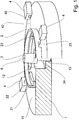
- a device for radiation welding internal circumferential surfaces 53 of a workpiece 5 by means of laser beams 41 basically includes a Supporting plate 1 for attaching a receptacle 2 for a workpiece 5, a conical mirror element 3 and a plurality of laser-optic modules 4.
- the laser-optic modules 4 each consist of a high-power diode laser (hereinafter referred to as HLDL) and a beam-shaping optics on a circle 7 are arranged at equal distances from one another and to a center of the circular line 7.
- HLDL high-power diode laser
- a beam exit surface 46 as a reference base for distances from one another, a beam axis 42 of the laser-optic modules 4 can be understood.
- the laser-optics modules 4 each emit a divergent laser beam 41 with the beam axis 42 in an emission plane 8 and radially to the center of the circular line 7.
- the conical mirror element 3 has a body axis which is perpendicular to the Abstrahlebene 8 and through the center of the circular line 7, wherein a cone angle ⁇ of the mirror element 3 is smaller than 30 °, so that the incident laser beams 41 directly into a welding plane 9, the one Weld distance A to the Abstrahlebene 8, are reflected on the inner peripheral surfaces 53 of the recorded in the receptacle 2 workpiece 5.
- the support plate 1 is a circular plate made of a rigid and laser-resistant material, for. B. of metal.
- a cylindrical recess 12 is co-axially to a perpendicular to the surface 11 oriented symmetry axis 6 of the support plate 1 is introduced.
- the conical mirror element 3 is arranged in the cylindrical recess 12.
- the conical mirror element 3 is a rotationally symmetrical body whose body axis is co-axial to the axis of symmetry 6 oriented. It has between a circular base surface 32 and a comparatively smaller circular top surface 33, a reflective jacket surface 31 with the specified cone angle ⁇ . At the base 32, the mirror element 3 is extended with a coaxial with the body axis arranged, cylindrical holder 34. The holder 34 is received at the bottom of the recess 12 axially along the symmetry axis 6 movable in an adjusting device 13 on the support plate 1.
- the laser-optic modules 4 are arranged in a circle and distributed uniformly about the axis of symmetry 6.
- the Laser-optic modules 4 are each aligned with the beam axis 42 of the outgoing laser beam 41 in the radial direction to the axis of symmetry 6, so that the beam axes 42 intersect on the axis of symmetry 6.
- the beam axes 42 all run in the parallel and at a fixed distance from the surface 11 lying Abstrahlebene 8.
- the laser beams 41 are incident on the reflective surface 31 of the conical mirror element 3 and are reflected directly onto the workpiece 5, wherein the beam axes 42 in the welding plane 9 impinge on the workpiece 5, which is further away from the surface 11 by the welding distance A than the Abstrahlebene. 8
- the receptacle 2 is co-centrically attached to the axis of symmetry 6 on the surface 11.
- the receptacle 2 is annular, designed in the form of an L-profile.
- the L-profile is formed from a bearing ring resting against the surface 11 and a centering ring seated on the bearing ring within the outer diameter of the bearing ring.
- the support ring is at least so high that a bearing surface 21 facing away from the surface 11 of the support ring is above the Abstrahlebene 8.
- the support surface 21 is oriented parallel to the surface 11.
- radial jet passages 23 are introduced into the support ring below the support surface 21, which allow the unhindered passage of the laser beams 41 through the receptacle 2 in the emission plane 8.
- the inner diameter of the centering ring is smaller than the outer diameter of the support ring and is used as a centering surface 22 for the workpiece 5. At the support surface 21 and the centering surface 22, the workpiece 5 is aligned in the device.
- the transmission welding is used in axisymmetric workpieces 5, in which a workpiece part 51 which is transparent to the laser beams 41 is arranged inside a workpiece part 51 which absorbs the laser beams 41 and which is accessible for welding only from the interior of the workpiece 5.
- both the transparent and the absorbent are Workpiece part 51/52 executed in the form of a thin-walled hollow cylinder.
- the transparent workpiece part 51 is inserted into the absorbent workpiece part 52, so that both workpiece parts 51/52, at least in a circumferential section of opposing surfaces, directly touch.
- the workpiece parts 51/52 form the inner circumferential surface 53 to be welded.
- the telescoped workpiece parts 51/52 are inserted into the receptacle 2 so that both workpiece parts 51/52 rest directly on the support surface 21 with an end face facing the device and the workpiece 5 is positioned in the axial direction to the weld plane 9 (FIG. Fig. 2a ).
- the absorbent workpiece part 52 also bears directly on the centering surface 22, whereby the inner circumferential surfaces 53 in the radial direction, co-centric to the mirror element 3 is aligned ( Fig. 2b ).
- the receptacle 2 is basically adapted to the dimensions of the workpiece 5.
- the device exploits the special radiation properties of the HLDL, which is advantageously suitable for the penetration welding of plastics.
- the HLDL radiate in two mutually perpendicular and through the beam axis 42 extending planes with different beam divergence angles. In the plane designated as "fast-axis" 44, the beam divergence is many times greater than in the other plane designated as “slow-axis” 43.
- the beam-shaping optical system is arranged upstream, with which the beam divergence angle is reduced to approximately 0.5 °.
- the beam divergence angle of the slow-axis 43 is left unchanged at about 3.5 °. After passing through the beam shaping optics, the slow axis 43 of the laser beam 41 thus has a greater divergence than the fast axis 44.
- the laser-optic modules 4 are mounted on the support plate 1 so that the fast-axis 44 is oriented vertically to the surface 11 in a vertical plane and the slow-axis 43 parallel to the surface 11 in the Abstrahlebene 8.
- the laser beam 41 has a beam profile that extends almost linearly in the emission plane 8.
- the laser beam 41 has in the vertical plane a much lower divergence than in the Fig. 2b illustrated Abstrahlebene 8.
- the laser beams 41 emanating from the laser-optical modules 4 pass through the beam passages 23 of the receptacle 2 below the workpiece 5 positioned in the receptacle 2 and impinge on the mirror element 3.
- the laser beams 41 are deflected in accordance with the cone angle ⁇ so that they are directed in the welding plane 9 directly on the inner circumferential surface 53.
- the welding plane 9 extends according to the cone angle ⁇ at the points by the inner circumferential surfaces 53 of the workpiece 5, at which the laser beams 41 impinge on the inner peripheral surfaces 53 and form a weld.
- the laser beam 41 strikes the corresponding to the cone angle ⁇ inclined lateral surface 31.
- the deflection of the laser beam 41 from the plane of abstraction 8 takes place in the vertical plane with priority.
- the laser beam 41 strikes, as in FIG Fig. 2b shown in a convex circumferential segment of the mirror element 3 on the lateral surface 31, so that in the welding plane 9 is dependent on the radius of the mirror element 3 widening of the laser beam 41.
- the cone angle ⁇ is adapted to the dimensions of the workpiece 5 or of the mirror element 3 and to a workpiece-specific welding distance A between the end faces resting on the bearing surface 21 and the inner peripheral surfaces 53 of the workpiece 5 to be welded.
- the welding distance A is kept as low as possible, so that the weld is in the vicinity of the end faces of the workpiece 5. Accordingly, the smallest possible cone angle ⁇ in the range of up to 30 ° are used on the mirror element 3.
- the small cone angles ⁇ have the advantage that the laser beams 41 impinging on the lateral surface 31 in the emission plane 8 with the larger divergence angle scarcely affect the reflection in the welding plane 9 be distorted.
- Fig. 2b is a single laser-optics module 4 visible with complete course of the laser beam 41.
- a small overlap region 45 is formed between adjacent laser beams 41.
- the overlap region 45 is necessary since the individual laser beams 41 generally have a Gaussian intensity distribution, the intensity decreasing continuously starting from the beam axis 42 towards the edge of the laser beam 41. The lack of intensity is compensated by the edges of two laser beams 41 are superimposed, so that even in these areas the formation of a closed and thus media-tight weld is guaranteed.
- the widening of the laser beams 41 in the welding plane 9 and thus the size of the overlapping area 45 can be changed by the axially movable mirror element 3.
- the mirror element 3 is added via the holder 34 in the adjusting device 13 of the support plate 1.
- the level of abstraction 8 can be steplessly adjusted between a lower and a lower level Adjust the upper position.
- In the lower position is the mirror element 3 with the top surface 33 just above the Abstrahlebene 8, so that the mirror element 3 is almost completely recessed in the recess 12 of the support plate 1.
- In the upper position it is with the base 32 just below the Abstrahlebene 8 so that the mirror element 3 is almost completely out of the recess 12 out.
- the radius of the mirror element 3 is optimized in the middle between base 32 and top surface 33 of the mirror element 3 to a workpiece diameter, that in a middle position between the upper and lower position, a medium overlap region 45 is achieved on the inner circumferential surfaces 53, the can be optimized in the direction of increasing or decreasing overlap.
- a threaded connection is used in the simplest case, in which the likewise threaded holder 34 can be screwed together with the mirror element 3 and unscrew. It can also be used linear actuators of any shape, which already form the holder 34, to which the conical mirror element 3 is attached.
- the mirror element 3 is shown in the lower position. In this position, the laser beam 41 strikes close to the cover surface 33 on the lateral surface 31 with a comparatively small radius. As in Fig. 3a shown, the axial adjustment due to the unchanged cone angle ⁇ has no visible effect on the position of the welding plane 9 in the vertical plane.
- the axial adjustment of the mirror element 3 relative to the Abstrahlebene 8 and the determination of the radii and the cone angle ⁇ allows almost any adjustment of the size of the overlap region 45 of the laser beams 41 in the welding plane 9 and thus a secure execution of self-contained and media-tight weld.
- the use of a larger number of laser-optic modules 4 is advantageous if a mirror element 3 with a comparatively large cone angle ⁇ is used. This is necessary when the inner peripheral surface 53 and thus the welding plane 9 is deeper in the interior of the workpiece 5 and the peripheral surface 53 thus has a comparatively large welding distance A. Under otherwise unchanged conditions, the larger cone angle .alpha. Causes portions of the laser beam 41 far away from the beam axis 42 in the emission plane 8, which impinge on the radius of the lateral surface 31 more tangentially than in the radial direction, no longer to be linear on the inner circumferential surfaces 53 can be imaged in the welding plane 9, but are distorted arcuate. As a result, it is no longer possible to set the overlapping area 45 in a defined manner.
- the use of the larger number of laser-optic modules 4 makes sense here.
- the required for the production of the closed weld beam divergence angle in the Abstrahlebene 8, z. B. by optical means can be reduced, whereby the arcuate distortions are restricted.
- the reduced beam divergence angle also reduces the overlap area 53.
- the number of laser-optic modules 4 is increased and, if possible, the distance between the laser-optic module 4 and the inner peripheral surfaces 53 is reduced.
- the closed weld is then achieved by the larger number of laser beams 41.
- the smallest possible number of laser-optic modules 4 are maintained. This is made possible by using suitable optics between the laser-optic modules 4 and the conical mirror element 3.
- the suitable optics form the laser beams 41 linearly in the welding plane 9, by counteracting the arcuate distortion of the far away from the beam axis 42 portions of the laser beams 41.
- the laser-optical modules 4 can be displaced along the beam axis 42 in the radial direction, so that the distance to the axis of symmetry 6 changes. A smaller distance reduces and a larger distance increases the expansion of the laser beams 41 in the radiation plane.
- the lateral surface 31 is slightly concave in another embodiment.
- the mirror element 3 thus achieves a focusing effect in the vertical plane of the fast-axis 44. Due to the focusing effect, the increase in the expansion of the laser beam 41 occurring due to the greater distance between laser-optical module 4 and inner peripheral surfaces 53 is reduced and a narrower weld seam is achieved at greater distances.
Landscapes
- Physics & Mathematics (AREA)
- Optics & Photonics (AREA)
- Engineering & Computer Science (AREA)
- Mechanical Engineering (AREA)
- General Physics & Mathematics (AREA)
- Electromagnetism (AREA)
- Plasma & Fusion (AREA)
- Health & Medical Sciences (AREA)
- Toxicology (AREA)
- Microelectronics & Electronic Packaging (AREA)
- Laser Beam Processing (AREA)
Claims (4)
- Dispositif de soudage par transmission à deux surfaces circonférentielles internes d'une pièce (5)
au moyen de faisceaux laser (41) comprenant plusieurs modules optiques à laser (4), qui sont chacun constitué d'un laser à diode de haute puissance et d'une optique de formation de faisceau, les modules optiques à laser (4) étant tous disposés sur une ligne de cercle (7) avec le même écartement entre eux et du centre de la ligne de cercle (7) et émettant un faisceau laser (41) divergent respectif avec un axe de faisceau (42) dans un plan de rayonnement (8), cette émission s'effectuant radialement vers le centre de la ligne de cercle (7),
une optique de déviation à symétrie de révolution, l'axe de corps de l'optique de déviation étant disposé perpendiculairement au plan de rayonnement (8) et traversant le centre de la ligne de cercle (7) et
un réceptacle (2), pour pouvoir disposer la pièce (5), avec deux surfaces circonférentielles internes à symétrie axiale, avec son axe de symétrie (6) de manière coaxiale à l'axe de corps de l'optique de déviation à symétrie de révolution, caractérisé en ce que,
l'optique de déviation à symétrie de révolution est un élément de miroir conique (3), ayant un angle de cône (α) inférieur à 30°, de sorte que les faisceaux laser (41) incidents sont réfléchi directement dans un plan de soudage (9), ayant une distance de soudage (A) au plan de rayonnement (8), sur les surfaces circonférentielles internes (53) de la pièce (5) reçue dans le réceptacle (2). - Dispositif selon la revendication 1, caractérisé en ce que l'élément de miroir conique (3) est ajustable perpendiculairement au plan de rayonnement (8) pour influencer l'expansion de faisceau des faisceaux laser (41).
- Dispositif selon la revendication 1, caractérisé en ce que l'élément de miroir conique (3) a un angle de cône (α) dans la gamme de 2°à 10°.
- Dispositif selon la revendication 1, caractérisé en ce que l'élément de miroir conique (3) a une surface latérale réfléchissante (31) de forme concave.
Applications Claiming Priority (1)
| Application Number | Priority Date | Filing Date | Title |
|---|---|---|---|
| DE201310104599 DE102013104599B3 (de) | 2013-05-06 | 2013-05-06 | Vorrichtung zum Durchstrahlschweißen innenliegender Umfangsflächen eines Werkstücks mittels Laserstrahlung |
Publications (3)
| Publication Number | Publication Date |
|---|---|
| EP2801471A1 EP2801471A1 (fr) | 2014-11-12 |
| EP2801471B1 true EP2801471B1 (fr) | 2016-03-30 |
| EP2801471B8 EP2801471B8 (fr) | 2016-06-01 |
Family
ID=50098752
Family Applications (1)
| Application Number | Title | Priority Date | Filing Date |
|---|---|---|---|
| EP14166495.3A Active EP2801471B8 (fr) | 2013-05-06 | 2014-04-30 | Dispositif de soudage par transmission de surfaces circonférentielles internes d'une pièce au moyen d'un rayonnement laser |
Country Status (3)
| Country | Link |
|---|---|
| EP (1) | EP2801471B8 (fr) |
| CN (1) | CN204054654U (fr) |
| DE (1) | DE102013104599B3 (fr) |
Cited By (1)
| Publication number | Priority date | Publication date | Assignee | Title |
|---|---|---|---|---|
| US10781926B2 (en) | 2016-04-12 | 2020-09-22 | Gemue Gebr. Mueller Apparatebau Gmbh & Co. Kommanditgesellschaft | Valve body and method for producing the valve body |
Families Citing this family (1)
| Publication number | Priority date | Publication date | Assignee | Title |
|---|---|---|---|---|
| CN112147744B (zh) * | 2020-09-30 | 2022-04-15 | 广东瑞谷光网通信股份有限公司 | 一种新型调节环及光发射组件的组装方法 |
Family Cites Families (1)
| Publication number | Priority date | Publication date | Assignee | Title |
|---|---|---|---|---|
| DE102004003696B4 (de) * | 2004-01-24 | 2017-02-16 | Limo Patentverwaltung Gmbh & Co. Kg | Vorrichtung zum simultanen Laserschweißen |
-
2013
- 2013-05-06 DE DE201310104599 patent/DE102013104599B3/de active Active
-
2014
- 2014-04-30 EP EP14166495.3A patent/EP2801471B8/fr active Active
- 2014-05-06 CN CN201420229421.7U patent/CN204054654U/zh not_active Expired - Lifetime
Cited By (1)
| Publication number | Priority date | Publication date | Assignee | Title |
|---|---|---|---|---|
| US10781926B2 (en) | 2016-04-12 | 2020-09-22 | Gemue Gebr. Mueller Apparatebau Gmbh & Co. Kommanditgesellschaft | Valve body and method for producing the valve body |
Also Published As
| Publication number | Publication date |
|---|---|
| CN204054654U (zh) | 2014-12-31 |
| DE102013104599B3 (de) | 2014-03-06 |
| EP2801471A1 (fr) | 2014-11-12 |
| EP2801471B8 (fr) | 2016-06-01 |
Similar Documents
| Publication | Publication Date | Title |
|---|---|---|
| DE69527858T2 (de) | Optische Einrichtung zur Werkstoffbearbeitung mittels Laser | |
| DE102009021448B3 (de) | Vorrichtung und Verfahren zur Umfangsbearbeitung eines Materialstranges mittels Laser | |
| DE102008022014B3 (de) | Dynamische Strahlumlenkung eines Laserstrahls | |
| EP3045021B1 (fr) | Système de guidage de faisceau et dispositif générateur de rayonnement euv équipé d'un système de superposition | |
| EP3414552A1 (fr) | Cellule à long parcours | |
| EP2591910B1 (fr) | Dispositif de liaison de deux pièces le long d'un cordon de soudure au moyen d'un soudage par rayonnement transmis | |
| WO2008080731A1 (fr) | Dispositif de soudage par rayon laser comprenant un dispositif optique pour convertir le rayon laser en un rayon laser de forme annulaire ainsi que procédé correspondant de soudage par rayon laser | |
| DE102015116033A1 (de) | Laserbearbeitungsvorrichtung, die in der Lage ist, den Durchmesser des fokussierten Strahls zu vergrössern | |
| DE102015104411A1 (de) | Laserstrahlfügeverfahren und Laserbearbeitungsoptik | |
| DE102017010055A1 (de) | Laserstrahlschweißen von geometrischen Figuren mit OCT-Nahtführung | |
| DE102004003696B4 (de) | Vorrichtung zum simultanen Laserschweißen | |
| DE102007018400A1 (de) | Optisches System für einen Lasermaterialbearbeitungskopf | |
| EP2439013B1 (fr) | Dispositif de traitement simultané d'une pièce usinée à l'aide de rayons laser | |
| DE102011119478B4 (de) | Vorrichtung zur fremdbeleuchteten Visualisierung eines mittels eines hochenergetischen Bearbeitungsstrahls erfolgenden Bearbeitungsprozesses sowie Umlenkelement | |
| DE10261422B4 (de) | Laserschweiß- und lötverfahren sowie Vorrichtung dazu | |
| DE4202606C2 (de) | Vorrichtung zum Fokussieren eines Lichtbündels in mehreren Fokuspunkten | |
| DE3933057C2 (fr) | ||
| DE102013104599B3 (de) | Vorrichtung zum Durchstrahlschweißen innenliegender Umfangsflächen eines Werkstücks mittels Laserstrahlung | |
| DE4339661C2 (de) | Verfahren zum Herstellen von röhrenförmigen Rohlingen aus Fein- oder Feinstblech | |
| DE102016010508A1 (de) | Vorrichtung, Bearbeitungsvorrichtung und Verfahren zum Durchführen eines Bearbeitungsprozesses mittels eines hochenergetischen Bearbeitungsstrahls unter Anpassung des Bearbeitstrahls nach Maßgabe einer aktuellen Bearbeitungssituation | |
| DE102012110165A1 (de) | Vorrichtung zum Verbinden zweier Werkstückteile mit Bereichen unterschiedlicher Eigenschaften mittels Durchstrahlschweißen | |
| EP1491279A1 (fr) | Procédé de soudage multifocal et appareil de soudage | |
| DE3711905C2 (fr) | ||
| DE102018100549B3 (de) | Verfahren und Vorrichtung zum Laserhärten von Werkstücken | |
| DE4034744C2 (de) | Vorrichtung zur variablen Laserstrahlteilung und Führung der Teilstrahlen |
Legal Events
| Date | Code | Title | Description |
|---|---|---|---|
| PUAI | Public reference made under article 153(3) epc to a published international application that has entered the european phase |
Free format text: ORIGINAL CODE: 0009012 |
|
| 17P | Request for examination filed |
Effective date: 20140430 |
|
| AK | Designated contracting states |
Kind code of ref document: A1 Designated state(s): AL AT BE BG CH CY CZ DE DK EE ES FI FR GB GR HR HU IE IS IT LI LT LU LV MC MK MT NL NO PL PT RO RS SE SI SK SM TR |
|
| AX | Request for extension of the european patent |
Extension state: BA ME |
|
| RIN1 | Information on inventor provided before grant (corrected) |
Inventor name: WOLLMANN, WERNER Inventor name: LANGEBACH, DR. JAN Inventor name: WITTENBECHER, WOLFGANG Inventor name: SCHELLER, TORSTEN |
|
| R17P | Request for examination filed (corrected) |
Effective date: 20150421 |
|
| RBV | Designated contracting states (corrected) |
Designated state(s): AL AT BE BG CH CY CZ DE DK EE ES FI FR GB GR HR HU IE IS IT LI LT LU LV MC MK MT NL NO PL PT RO RS SE SI SK SM TR |
|
| RIC1 | Information provided on ipc code assigned before grant |
Ipc: G02B 27/09 20060101ALI20150805BHEP Ipc: B29C 65/16 20060101AFI20150805BHEP Ipc: B23K 26/064 20140101ALI20150805BHEP |
|
| GRAP | Despatch of communication of intention to grant a patent |
Free format text: ORIGINAL CODE: EPIDOSNIGR1 |
|
| INTG | Intention to grant announced |
Effective date: 20150930 |
|
| GRAS | Grant fee paid |
Free format text: ORIGINAL CODE: EPIDOSNIGR3 |
|
| GRAA | (expected) grant |
Free format text: ORIGINAL CODE: 0009210 |
|
| REG | Reference to a national code |
Ref country code: DE Ref legal event code: R108 Ref document number: 502014000522 Country of ref document: DE |
|
| AK | Designated contracting states |
Kind code of ref document: B1 Designated state(s): AL AT BE BG CH CY CZ DE DK EE ES FI FR GB GR HR HU IE IS IT LI LT LU LV MC MK MT NL NO PL PT RO RS SE SI SK SM TR |
|
| REG | Reference to a national code |
Ref country code: GB Ref legal event code: FG4D Free format text: NOT ENGLISH |
|
| REG | Reference to a national code |
Ref country code: CH Ref legal event code: EP |
|
| REG | Reference to a national code |
Ref country code: AT Ref legal event code: REF Ref document number: 784882 Country of ref document: AT Kind code of ref document: T Effective date: 20160415 |
|
| RBV | Designated contracting states (corrected) |
Designated state(s): AL AT BE BG CH CY CZ DK EE ES FI FR GB GR HR HU IE IS IT LI LT LU LV MC MK MT NL NO PL PT RO RS SE SI SK SM TR |
|
| REG | Reference to a national code |
Ref country code: IE Ref legal event code: FG4D Free format text: LANGUAGE OF EP DOCUMENT: GERMAN |
|
| REG | Reference to a national code |
Ref country code: CH Ref legal event code: NV Representative=s name: FELBER AND PARTNER AG, CH |
|
| REG | Reference to a national code |
Ref country code: DE Ref legal event code: R096 Ref document number: 502014000522 Country of ref document: DE |
|
| REG | Reference to a national code |
Ref country code: FR Ref legal event code: PLFP Year of fee payment: 3 |
|
| REG | Reference to a national code |
Ref country code: DE Ref legal event code: R107 Ref document number: 502014000522 Country of ref document: DE |
|
| REG | Reference to a national code |
Ref country code: LT Ref legal event code: MG4D |
|
| PG25 | Lapsed in a contracting state [announced via postgrant information from national office to epo] |
Ref country code: GR Free format text: LAPSE BECAUSE OF FAILURE TO SUBMIT A TRANSLATION OF THE DESCRIPTION OR TO PAY THE FEE WITHIN THE PRESCRIBED TIME-LIMIT Effective date: 20160701 Ref country code: HR Free format text: LAPSE BECAUSE OF FAILURE TO SUBMIT A TRANSLATION OF THE DESCRIPTION OR TO PAY THE FEE WITHIN THE PRESCRIBED TIME-LIMIT Effective date: 20160330 Ref country code: FI Free format text: LAPSE BECAUSE OF FAILURE TO SUBMIT A TRANSLATION OF THE DESCRIPTION OR TO PAY THE FEE WITHIN THE PRESCRIBED TIME-LIMIT Effective date: 20160330 Ref country code: NO Free format text: LAPSE BECAUSE OF FAILURE TO SUBMIT A TRANSLATION OF THE DESCRIPTION OR TO PAY THE FEE WITHIN THE PRESCRIBED TIME-LIMIT Effective date: 20160630 |
|
| REG | Reference to a national code |
Ref country code: NL Ref legal event code: MP Effective date: 20160330 |
|
| PG25 | Lapsed in a contracting state [announced via postgrant information from national office to epo] |
Ref country code: RS Free format text: LAPSE BECAUSE OF FAILURE TO SUBMIT A TRANSLATION OF THE DESCRIPTION OR TO PAY THE FEE WITHIN THE PRESCRIBED TIME-LIMIT Effective date: 20160330 Ref country code: LV Free format text: LAPSE BECAUSE OF FAILURE TO SUBMIT A TRANSLATION OF THE DESCRIPTION OR TO PAY THE FEE WITHIN THE PRESCRIBED TIME-LIMIT Effective date: 20160330 Ref country code: BE Free format text: LAPSE BECAUSE OF NON-PAYMENT OF DUE FEES Effective date: 20160430 Ref country code: SE Free format text: LAPSE BECAUSE OF FAILURE TO SUBMIT A TRANSLATION OF THE DESCRIPTION OR TO PAY THE FEE WITHIN THE PRESCRIBED TIME-LIMIT Effective date: 20160330 Ref country code: LT Free format text: LAPSE BECAUSE OF FAILURE TO SUBMIT A TRANSLATION OF THE DESCRIPTION OR TO PAY THE FEE WITHIN THE PRESCRIBED TIME-LIMIT Effective date: 20160330 |
|
| PG25 | Lapsed in a contracting state [announced via postgrant information from national office to epo] |
Ref country code: NL Free format text: LAPSE BECAUSE OF FAILURE TO SUBMIT A TRANSLATION OF THE DESCRIPTION OR TO PAY THE FEE WITHIN THE PRESCRIBED TIME-LIMIT Effective date: 20160330 |
|
| PG25 | Lapsed in a contracting state [announced via postgrant information from national office to epo] |
Ref country code: IS Free format text: LAPSE BECAUSE OF FAILURE TO SUBMIT A TRANSLATION OF THE DESCRIPTION OR TO PAY THE FEE WITHIN THE PRESCRIBED TIME-LIMIT Effective date: 20160730 Ref country code: EE Free format text: LAPSE BECAUSE OF FAILURE TO SUBMIT A TRANSLATION OF THE DESCRIPTION OR TO PAY THE FEE WITHIN THE PRESCRIBED TIME-LIMIT Effective date: 20160330 Ref country code: PL Free format text: LAPSE BECAUSE OF FAILURE TO SUBMIT A TRANSLATION OF THE DESCRIPTION OR TO PAY THE FEE WITHIN THE PRESCRIBED TIME-LIMIT Effective date: 20160330 |
|
| PG25 | Lapsed in a contracting state [announced via postgrant information from national office to epo] |
Ref country code: SK Free format text: LAPSE BECAUSE OF FAILURE TO SUBMIT A TRANSLATION OF THE DESCRIPTION OR TO PAY THE FEE WITHIN THE PRESCRIBED TIME-LIMIT Effective date: 20160330 Ref country code: SM Free format text: LAPSE BECAUSE OF FAILURE TO SUBMIT A TRANSLATION OF THE DESCRIPTION OR TO PAY THE FEE WITHIN THE PRESCRIBED TIME-LIMIT Effective date: 20160330 Ref country code: PT Free format text: LAPSE BECAUSE OF FAILURE TO SUBMIT A TRANSLATION OF THE DESCRIPTION OR TO PAY THE FEE WITHIN THE PRESCRIBED TIME-LIMIT Effective date: 20160801 Ref country code: CZ Free format text: LAPSE BECAUSE OF FAILURE TO SUBMIT A TRANSLATION OF THE DESCRIPTION OR TO PAY THE FEE WITHIN THE PRESCRIBED TIME-LIMIT Effective date: 20160330 Ref country code: RO Free format text: LAPSE BECAUSE OF FAILURE TO SUBMIT A TRANSLATION OF THE DESCRIPTION OR TO PAY THE FEE WITHIN THE PRESCRIBED TIME-LIMIT Effective date: 20160330 Ref country code: ES Free format text: LAPSE BECAUSE OF FAILURE TO SUBMIT A TRANSLATION OF THE DESCRIPTION OR TO PAY THE FEE WITHIN THE PRESCRIBED TIME-LIMIT Effective date: 20160330 |
|
| REG | Reference to a national code |
Ref country code: IE Ref legal event code: MM4A |
|
| PG25 | Lapsed in a contracting state [announced via postgrant information from national office to epo] |
Ref country code: DK Free format text: LAPSE BECAUSE OF FAILURE TO SUBMIT A TRANSLATION OF THE DESCRIPTION OR TO PAY THE FEE WITHIN THE PRESCRIBED TIME-LIMIT Effective date: 20160330 |
|
| PLBE | No opposition filed within time limit |
Free format text: ORIGINAL CODE: 0009261 |
|
| STAA | Information on the status of an ep patent application or granted ep patent |
Free format text: STATUS: NO OPPOSITION FILED WITHIN TIME LIMIT |
|
| 26N | No opposition filed |
Effective date: 20170103 |
|
| REG | Reference to a national code |
Ref country code: FR Ref legal event code: PLFP Year of fee payment: 4 |
|
| PG25 | Lapsed in a contracting state [announced via postgrant information from national office to epo] |
Ref country code: IE Free format text: LAPSE BECAUSE OF NON-PAYMENT OF DUE FEES Effective date: 20160430 Ref country code: SI Free format text: LAPSE BECAUSE OF FAILURE TO SUBMIT A TRANSLATION OF THE DESCRIPTION OR TO PAY THE FEE WITHIN THE PRESCRIBED TIME-LIMIT Effective date: 20160330 |
|
| REG | Reference to a national code |
Ref country code: FR Ref legal event code: PLFP Year of fee payment: 5 |
|
| PG25 | Lapsed in a contracting state [announced via postgrant information from national office to epo] |
Ref country code: HU Free format text: LAPSE BECAUSE OF FAILURE TO SUBMIT A TRANSLATION OF THE DESCRIPTION OR TO PAY THE FEE WITHIN THE PRESCRIBED TIME-LIMIT; INVALID AB INITIO Effective date: 20140430 |
|
| PG25 | Lapsed in a contracting state [announced via postgrant information from national office to epo] |
Ref country code: MK Free format text: LAPSE BECAUSE OF FAILURE TO SUBMIT A TRANSLATION OF THE DESCRIPTION OR TO PAY THE FEE WITHIN THE PRESCRIBED TIME-LIMIT Effective date: 20160330 Ref country code: CY Free format text: LAPSE BECAUSE OF FAILURE TO SUBMIT A TRANSLATION OF THE DESCRIPTION OR TO PAY THE FEE WITHIN THE PRESCRIBED TIME-LIMIT Effective date: 20160330 Ref country code: MT Free format text: LAPSE BECAUSE OF FAILURE TO SUBMIT A TRANSLATION OF THE DESCRIPTION OR TO PAY THE FEE WITHIN THE PRESCRIBED TIME-LIMIT Effective date: 20160330 Ref country code: MC Free format text: LAPSE BECAUSE OF FAILURE TO SUBMIT A TRANSLATION OF THE DESCRIPTION OR TO PAY THE FEE WITHIN THE PRESCRIBED TIME-LIMIT Effective date: 20160330 Ref country code: LU Free format text: LAPSE BECAUSE OF NON-PAYMENT OF DUE FEES Effective date: 20160430 |
|
| PG25 | Lapsed in a contracting state [announced via postgrant information from national office to epo] |
Ref country code: BG Free format text: LAPSE BECAUSE OF FAILURE TO SUBMIT A TRANSLATION OF THE DESCRIPTION OR TO PAY THE FEE WITHIN THE PRESCRIBED TIME-LIMIT Effective date: 20160330 |
|
| PG25 | Lapsed in a contracting state [announced via postgrant information from national office to epo] |
Ref country code: TR Free format text: LAPSE BECAUSE OF FAILURE TO SUBMIT A TRANSLATION OF THE DESCRIPTION OR TO PAY THE FEE WITHIN THE PRESCRIBED TIME-LIMIT Effective date: 20160330 Ref country code: AL Free format text: LAPSE BECAUSE OF FAILURE TO SUBMIT A TRANSLATION OF THE DESCRIPTION OR TO PAY THE FEE WITHIN THE PRESCRIBED TIME-LIMIT Effective date: 20160330 |
|
| GBPC | Gb: european patent ceased through non-payment of renewal fee |
Effective date: 20180430 |
|
| PG25 | Lapsed in a contracting state [announced via postgrant information from national office to epo] |
Ref country code: GB Free format text: LAPSE BECAUSE OF NON-PAYMENT OF DUE FEES Effective date: 20180430 |
|
| REG | Reference to a national code |
Ref country code: AT Ref legal event code: MM01 Ref document number: 784882 Country of ref document: AT Kind code of ref document: T Effective date: 20190430 |
|
| PG25 | Lapsed in a contracting state [announced via postgrant information from national office to epo] |
Ref country code: AT Free format text: LAPSE BECAUSE OF NON-PAYMENT OF DUE FEES Effective date: 20190430 |
|
| PGFP | Annual fee paid to national office [announced via postgrant information from national office to epo] |
Ref country code: CH Payment date: 20240501 Year of fee payment: 11 |
|
| PGFP | Annual fee paid to national office [announced via postgrant information from national office to epo] |
Ref country code: IT Payment date: 20240430 Year of fee payment: 11 Ref country code: FR Payment date: 20240419 Year of fee payment: 11 |
|
| REG | Reference to a national code |
Ref country code: CH Ref legal event code: H13 Free format text: ST27 STATUS EVENT CODE: U-0-0-H10-H13 (AS PROVIDED BY THE NATIONAL OFFICE) Effective date: 20251125 |
|
| PG25 | Lapsed in a contracting state [announced via postgrant information from national office to epo] |
Ref country code: FR Free format text: LAPSE BECAUSE OF NON-PAYMENT OF DUE FEES Effective date: 20250430 |
|
| PG25 | Lapsed in a contracting state [announced via postgrant information from national office to epo] |
Ref country code: CH Free format text: LAPSE BECAUSE OF NON-PAYMENT OF DUE FEES Effective date: 20250430 |
|
| PG25 | Lapsed in a contracting state [announced via postgrant information from national office to epo] |
Ref country code: IT Free format text: LAPSE BECAUSE OF NON-PAYMENT OF DUE FEES Effective date: 20250430 |