EP2801549B1 - Dehnungssensor basierend auf Kohlenstoff-Nanoröhren und Verfahren zu dessen Herstellung - Google Patents
Dehnungssensor basierend auf Kohlenstoff-Nanoröhren und Verfahren zu dessen Herstellung Download PDFInfo
- Publication number
- EP2801549B1 EP2801549B1 EP14167525.6A EP14167525A EP2801549B1 EP 2801549 B1 EP2801549 B1 EP 2801549B1 EP 14167525 A EP14167525 A EP 14167525A EP 2801549 B1 EP2801549 B1 EP 2801549B1
- Authority
- EP
- European Patent Office
- Prior art keywords
- cnt
- strain sensor
- film
- fiber bundles
- resin layer
- Prior art date
- Legal status (The legal status is an assumption and is not a legal conclusion. Google has not performed a legal analysis and makes no representation as to the accuracy of the status listed.)
- Active
Links
Images




Classifications
-
- G—PHYSICS
- G01—MEASURING; TESTING
- G01L—MEASURING FORCE, STRESS, TORQUE, WORK, MECHANICAL POWER, MECHANICAL EFFICIENCY, OR FLUID PRESSURE
- G01L1/00—Measuring force or stress, in general
- G01L1/20—Measuring force or stress, in general by measuring variations in ohmic resistance of solid materials or of electrically-conductive fluids; by making use of electrokinetic cells, i.e. liquid-containing cells wherein an electrical potential is produced or varied upon the application of stress
- G01L1/22—Measuring force or stress, in general by measuring variations in ohmic resistance of solid materials or of electrically-conductive fluids; by making use of electrokinetic cells, i.e. liquid-containing cells wherein an electrical potential is produced or varied upon the application of stress using resistance strain gauges
- G01L1/2287—Measuring force or stress, in general by measuring variations in ohmic resistance of solid materials or of electrically-conductive fluids; by making use of electrokinetic cells, i.e. liquid-containing cells wherein an electrical potential is produced or varied upon the application of stress using resistance strain gauges constructional details of the strain gauges
-
- B—PERFORMING OPERATIONS; TRANSPORTING
- B82—NANOTECHNOLOGY
- B82Y—SPECIFIC USES OR APPLICATIONS OF NANOSTRUCTURES; MEASUREMENT OR ANALYSIS OF NANOSTRUCTURES; MANUFACTURE OR TREATMENT OF NANOSTRUCTURES
- B82Y30/00—Nanotechnology for materials or surface science, e.g. nanocomposites
-
- G—PHYSICS
- G01—MEASURING; TESTING
- G01L—MEASURING FORCE, STRESS, TORQUE, WORK, MECHANICAL POWER, MECHANICAL EFFICIENCY, OR FLUID PRESSURE
- G01L1/00—Measuring force or stress, in general
- G01L1/20—Measuring force or stress, in general by measuring variations in ohmic resistance of solid materials or of electrically-conductive fluids; by making use of electrokinetic cells, i.e. liquid-containing cells wherein an electrical potential is produced or varied upon the application of stress
-
- Y—GENERAL TAGGING OF NEW TECHNOLOGICAL DEVELOPMENTS; GENERAL TAGGING OF CROSS-SECTIONAL TECHNOLOGIES SPANNING OVER SEVERAL SECTIONS OF THE IPC; TECHNICAL SUBJECTS COVERED BY FORMER USPC CROSS-REFERENCE ART COLLECTIONS [XRACs] AND DIGESTS
- Y10—TECHNICAL SUBJECTS COVERED BY FORMER USPC
- Y10T—TECHNICAL SUBJECTS COVERED BY FORMER US CLASSIFICATION
- Y10T156/00—Adhesive bonding and miscellaneous chemical manufacture
- Y10T156/10—Methods of surface bonding and/or assembly therefor
- Y10T156/1089—Methods of surface bonding and/or assembly therefor of discrete laminae to single face of additional lamina
- Y10T156/1092—All laminae planar and face to face
Definitions
- the present invention relates to a strain sensor.
- a strain sensor that detects strain is constituted so as to detect strain from the resistance change of a resistive body with respect to strain (extension and contraction).
- a metal or semiconductor is generally used as this resistive body.
- the applications of a strain sensor are limited.
- CNT carbon nanotubes
- the present invention was achieved in view of the aforementioned circumstances, and has as its object to provide a strain sensor that is capable of inhibiting the occurrence of contamination of the CNT film by foreign substances and enhancing the durability of the sensor function while improving the linearity of the resistance change and responsiveness.
- the strain sensor of the present invention is defined in claim 1.
- the present invention provides a method for manufacturing a strain sensor.
- the manufacturing method of the invention is defined in claim 8.
- the strain sensor of the present invention is provided with a substrate that has flexibility, a carbon nanotube (CNT) film that is provided on the surface of this substrate and that has a plurality of CNT fibers oriented in one direction; and a pair of electrodes that are arranged at both ends in the orientation direction of the CNT fibers in the CNT film, in which the CNT film has a plurality of CNT fiber bundles that consist of the plurality of CNT fibers, and a resin layer that covers the peripheral surface of the plurality of the CNT fiber bundles and joins with the surface of the substrate.
- CNT carbon nanotube
- This strain sensor is capable of sensing strain by the change in electrical resistance of the CNT film upon extending or contracting in the direction of causing the pair of electrodes to respectively move away from or approach each other (electrode arrangement direction). Since the orientation direction of the CNT fiber bundles that the CNT film has and the electrode arrangement direction are approximately the same direction, and the peripheral surface of the CNT fiber bundles that consist of the plurality of CNT fibers is covered with the resin layer in this strain sensor, the linearity of the resistance change of the CNT film is high.
- the linearity of the resistance change is high.
- the periphery of the CNT fiber bundles of this strain sensor is covered with a resin layer. Also, the resin layer partially impregnates to the periphery of the CNT fiber bungles so as to form an impregnated portion.
- This resin layer and the impregnated portion play the role of a guide, and since a non-impregnated portion, which is not impregnated with the resin layer, of the CNT fiber bundle is prevented from coming into contact with other fiber bundles due to free movement other than in the extension/contraction direction, it is possible to inhibit unforeseen resistance changes, and further increase the linearity of the resistance change.
- the periphery of the CNT fiber bundles in the strain sensor of the present invention is covered with the resin layer and the impregnated portion as described above, when the CNT fibers in the CNT fiber bundles are broken, a space that is isolated from the outside is formed between the broken end portions of the CNT fibers.
- the pressure in this space is considered to be lower than the atmospheric pressure (negative pressure), and so during contraction of the strain sensor (during release of the strain), the contraction of the strain sensor is biased by the contraction force of this gap.
- friction among the CNT fibers and between the CNT fibers and the periphery resin is reduced, movement of the CNT fibers is not easily restricted by the residual stress of the resin. As a result, since the broken end portions of the CNT fibers quickly reestablish contact during contraction of the strain sensor, this strain sensor can obtain a high responsiveness.
- the CNT film has the resin layer and the impregnated portion that covers the periphery of the CNT fiber bundles, whereby it is possible to prevent contamination of the CNT film by foreign substances. Since the CNT fiber bundles and the resin layer are connected by the impregnated layer, it is possible to prevent from falling off of the CNT fibers so as to enhance the durability of the sensor function.
- the strain sensor of the present invention is capable of inhibiting the occurrence of contamination of the CNT film by foreign substances and enhancing the durability of the sensor function while improving the linearity of the resistance change and responsiveness. Accordingly, the strain sensor of the present invention can be widely utilized as a pressure sensor, a load cell, a torque sensor, a position sensor and the like.
- a strain sensor 1 is provided with a substrate 2, a CNT film 4 that is provided on the surface side of this substrate 2 and that has a plurality of CNT fibers oriented in one direction, and a pair of electrodes 3 that are arranged at both ends of the CNT fibers in the orientation direction A.
- the substrate 2 is a plate-shaped body that has flexibility.
- the size of the substrate 2 is not particularly limited, and for example the thickness may be between 10 ⁇ m and 5 mm, the width between 1 mm and 5 cm, and the length between 1 cm and 20 cm.
- the material of the substrate 2 is not particularly limited provided it has flexibility, with examples including synthetic resin, rubber, a nonwoven fabric, and a metal or metallic compound with a deformable shape or material.
- the substrate 2 should be an insulator or a material with a high resistance value, but in the case of using a material with a low resistance value such as metal, an insulating layer or a material with a high resistance value may be coated on the surface thereof.
- a synthetic resin or rubber is preferred, with rubber being particularly preferred. By using rubber, it is possible to further increase the flexibility of the substrate 2.
- Examples of a synthetic resin include for example phenol resin (PF), epoxy resin (EP), melamine resin (MF), and urea-formaldehyde resin (urea resin, UF), unsaturated polyester resin (UP), alkyd resin, polyurethane (PUR), thermosetting polyimide (PI), polyethylene (PE), high-density polyethylene (HDPE), medium-density polyethylene (MDPE), low-density polyethylene (LDPE), polypropylene (PP), polyvinyl chloride (PVC), polyvinylidene, polystyrene (PS), polyvinyl acetate (PVAc), acrylonitrile butadiene styrene resin (ABS), acrylonitrile-styrene resin (AS), polymethyl methacrylate (PMMA), polyamide (PA), polyacetal (POM), polycarbonate (PC), modified polyphenylene ether (m-PPE), polybutylene terephthalate (PBT), polyethylene terephthal
- Examples of the rubber include for example natural rubber (NR), isobutylene-isoprene rubber (IIR), polyisoprene rubber (IR), ethylene propylene rubber (EPDM), butadiene rubber (BR), urethane rubber (U), styrene-butadiene rubber (SBR), silicone rubber (Q), chloroprene rubber (CR), chlorosulphonated polyethylene rubber (CSM), acrylonitrile-butadiene rubber (NBR), chlorinated polyethylene (CM), acrylic rubber (ACM), epichlorohydrine rubber (CO, ECO), fluororubber (FKM), PDMS, and the like.
- natural rubber is preferred from the aspect of strength.
- the pair of electrodes 3 are allocated at both end portions of the substrate 2 in the longitudinal direction A of the surface (orientation direction of CNT fibers). Specifically, the electrodes 3 are respectively arranged on the surface of a pair of conductive layers 5 that are arranged spaced apart at both end portions in the longitudinal direction A of the surface of the substrate 2.
- Each conductive layer 5 raises the electrical connectivity of the electrode 3 and the CNT film 4.
- the material that forms the conductive layer 5 is not particularly limited provided it has conductivity, and for example it is possible to use a conductive rubber-based adhesive. By using an adhesive as the conductive layer 5, it is possible to increase the fixation of the substrate 2, the electrode 3 and the CNT film 4 at both ends, and so it is possible to improve the durability of the stain sensor 1.
- the electrode 3 has a belt-like shape.
- the pair of electrodes 3 is arranged in a mutually parallel manner in the width direction of the substrate 2.
- metal such as copper, silver, aluminum and the like.
- the shape of the electrodes 3 While it is possible for the shape of the electrodes 3 to be for example membranous, planar, meshlike and the like, it is preferable for them to be meshlike. By using meshlike electrodes 3 in this way, it is possible to raise the adhesion and fixation with the conductive layer 5. As this kind of mesh-shape electrode 3, it is possible to use a metal mesh, or one consisting of metal that is vapor deposited or sputtered on a nonwoven fabric. The electrode 3 may also be formed by the application of a conductive adhesive agent.
- the CNT film 4 has a plurality of CNT fiber bundles 6 consisting of a plurality of CNT fibers oriented in one direction and a resin layer 7 that covers the peripheral surface of the plurality of CNT resin bundles 6 and an impregnated portion. That is to say, the CNT fiber bundle 6 is constituted from a plurality of CNT fibers, and the resin layer 7 covers the periphery of this CNT fiber bundle 6. The resin layer 7 is partially impregnated to the periphery of the CNT fiber bundle 6 to form the impregnated portion.
- a non-impregnated portion which is not impregnated with the resin layer, is provided within the CNT fiber bundle 6 such that the non-impregnated portion is wrapped with the impregnated portion.
- the CNT film 4 has a rectangular shape in planar view, and both end portions of the CNT film 4 in the longitudinal direction A are connected with the respective electrode 3 via the conductive layer 5.
- the CNT film 4 has a plurality of CNT fiber bundles 6 that are oriented in one direction (the facing direction A of the pair of electrodes 3). Due to the CNT fiber bundles 6 being oriented in this way, in the case of strain being applied in a direction in which the pair of electrodes 3 move apart (the direction A), it is possible to obtain a resistance change of the strain sensor 1 arising from the breakage and separation of the CNT fibers that constitute the non-impregnated portion of each CNT fiber bundle 6, and expansion and contraction of the break space (gap) of each CNT fiber bundle 6.
- each CNT fiber bundle 6 has a bundle structure consisting of CNT fibers.
- CNT film 4 At an arbitrary cross section on the non-impregnated portion of any one of the CNT fiber bundles 6 (CNT film 4), there exist both CNT fibers that are not broken and gaps at which the CNT fibers are broken and separated.
- the pressure in this gap is considered to be lower than the atmospheric pressure (negative pressure), and so during contraction of the strain sensor 1 (during release of the strain), the contraction of the strain sensor is biased by the contraction force of this gap.
- this gap since friction among the CNT fibers and between the CNT fibers and the periphery resin is reduced, movement of the CNT fibers is not easily restricted by the residual stress of the resin.
- Each CNT fiber bundle 6 consists of a plurality of CNT fibers.
- a CNT fiber refers to a single, long CNT.
- the CNT fiber bundle 6 has connecting portions at which the end portions of CNT fibers connect.
- the CNT fibers connect in the longitudinal direction of the CNT fibers.
- the CNT film 4 by using the CNT fiber bundle 6 in which CNT fibers connect in the longitudinal direction, it is possible to form the CNT film 4 with a large length in the orientation direction of the CNT fiber bundle 6, and so it is possible to increase the longitudinal direction length of the strain sensor 1 and improve the sensitivity.
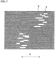
- the non-impregnated portions of the plurality of CNT fiber bundles 6 may have a break place P in the longitudinal direction A as shown in FIG. 2 .
- This break place P can be formed by, for example after laminating the CNT film 4 on the substrate 2, extending it in the longitudinal direction A.
- This break places P are preferably formed at a random locations of the non-impregnated portions in each CNT fiber bundle 6. Due to the break places P being formed randomly, the lengths (gaps) of the break places P are prevented from all changing (extending and contracting) at the same timing, and so it is possible to prevent a rapid fluctuation of the resistance change, and therefore possible to improve the linearity. Note that it is preferable for the CNT fiber to exist in fragments at this break place P. Also, a plurality of break places P may be formed in the non-impregnated portion of one CNT fiber bundle 6.
- the lower limit of the length of the break place P when stationary is preferably 5 ⁇ m, with 10 ⁇ m being more preferable. In the case of the length of the break place P being less than the lower limit, there is a risk of linearity of the resistance change during extension and contraction of the CNT film 4 not being sufficiently obtained.
- the upper limit of the length of the break place P when stationary is preferably 50 ⁇ m, with 40 ⁇ m being more preferable. In the case of the length of the break place P exceeding the upper limit, there is a risk of the resistance of the strain sensor 1 being unnecessarily high.
- a plurality of the CNT fiber bundles 6 may connect or make contact in a mesh shape by the connecting portions or the like.
- the end portions of three or more CNT fibers may join together at the connecting portion, or the end portions of two CNT fibers may be joined to the middle portion of another CNT fiber.
- the CNT fiber bundles 6 make close contact, and it is possible to reduce the resistance of the CNT film 4.
- the connecting portions of the CNT fiber bundles 6 become the main base point, and may connect or make contact with not only adjacent CNT fiber bundles 6, but also CNT fiber bundles 6 that leap over a number of them in between.
- connection between the CNT fiber bundles 6 refers to the connecting portion and the CNT fiber bundle 6 electrically connecting, with the case of an electrical connection between portions other than the connecting portion of the CNT fiber bundles 6 also included in a connection.
- Contact between the CNT fiber bundles 6 refers to the connecting portion and the CNT fiber bundle 6 being in contact but not electrically connected, with the case of portions other than the connecting portion of the CNT fiber bundles 6 being in contact but not electrically connected also included in contact.
- each CNT fiber is essentially in a state of being oriented in the longitudinal direction of the CNT fiber bundle 6, and not twisted.
- the connecting portion the CNT fibers are joined together by intermolecular force. For this reason, even in the case of a plurality of CNT fiber bundles 6 being connected in a mesh shape by the connecting portion, an increase in the resistance due to the presence of the connecting portion is inhibited.
- the CNT film 4 may consist of a single-layer structure or a multi-layer structure in which the CNT fiber bundles 6 are arranged approximately parallel in a planar shape. However, in order to ensure a certain degree of conductivity, a multi-layer structure is preferable.
- CNT fiber As the CNT fiber (CNT), it is possible to use either a single-layer single wall nanotube (SWNT), a multi-wall nanotube (MWNT), but from the point of conductivity and heat capacity, a MWNT is preferable, and a MWNT with a diameter of between 1.5 nm and 100 nm is more preferable.
- SWNT single-layer single wall nanotube
- MWNT multi-wall nanotube
- the CNT fiber It is possible to manufacture the CNT fiber with a publicly known method, and for example it can be manufactured by chemical vapor disposition (CVD), arc discharge, laser ablation, the DIPS method, direct injection pyrolytic synthesis (DIPS), the CoMoCAT process and the like.
- CVD chemical vapor disposition
- arc discharge laser ablation
- DIPS direct injection pyrolytic synthesis
- CoMoCAT CoMoCAT process
- MWNT CNT
- CVD that uses an iron catalyst and ethylene gas.
- an iron catalyst and ethylene gas In this case, after forming an iron or nickel film serving as the catalyst on a silica glass substrate or a silicon substrate with an oxide film, it is possible to obtain a CNT crystal of the desired length grown with a vertical orientation.
- the resin layer 7 is a layer that contains resin as the main component, and that covers the peripheral surface of the plurality of CNT fiber bundles 6.
- the main component of the resin layer include synthetic resin or rubber illustrated as the material of the substrate 2, with rubber being preferred among these. By using rubber, it can exhibit a sufficient CNT fiber protecting function with respect to large strain.
- the resin layer 7 is formed using an aqueous emulsion.
- An aqueous emulsion is an emulsion in which the main component of the dispersion medium is water. CNT is highly hydrophobic. For that reason, by forming the resin layer 7 using an aqueous emulsion, that is to say, by forming the resin layer 7 by for example coating with or immersing in an aqueous emulsion having resin as a dispersed material, it is possible to achieve a state in which the resin layer 7 is filled in the periphery of the CNT fiber bundle 6 without being completely impregnated in the interior of the CNT fiber bundle 6.
- the CNT fiber bundle 6 has a bundle structure that consists of a plurality of CNT fibers. Specifically, the plurality of CNT fibers in the CNT fiber bundle 6 form a long CNT fiber bundle 6 while mutually overlapping. In this case, the connection of the plurality of CNT fibers forms a long CNT fiber bundle 6 that is provided with a current path. This is the reason why CNT fibers do not lose their current path even when broken in the longitudinal direction.
- the resin layer 7 has not completely impregnated to the plurality of CNT fibers that form a minimum bundle structure, there is no problem even if it has partially impregnated the middle of the CNT fiber bundle 6 so as to form the impregnated portion.
- a bundle structure with a small diameter that constitutes the CNT fiber bundle 6 is considered to be a small diameter bundle in the CNT fiber bundle 6.
- the main component of the dispersion medium of the aqueous emulsion is water, a hydrophilic dispersion media such as, for example, alcohol may be contained.
- the dispersoid of the emulsion is ordinary resin, but aforementioned rubber, especially crude rubber, is preferable.
- polyurethane may be employed as the dispersoid.
- An example of this preferred emulsion is so-called latex, which uses water as the dispersion medium and rubber as the dispersoid, with natural rubber latex being preferred. By using natural rubber latex, it is possible to form a thin and strong protective layer.
- the resin layer 7 contains a coupling agent.
- the resin layer 7 includes a coupling agent, it is possible to cross-link the resin layer 7 and the CNT fiber bundles 6, and so it is possible to improve the joining force of the resin layer 7 and the CNT fiber bundles 6.
- an amino coupling agent or a silane coupling agent such as an amino silane coupling agent, an amino titanium coupling agent, and an amino aluminum coupling agent.
- the lower limit of the content of the coupling agent with respect to 100 pts. mass of the matrix resin of the resin layer 7 is preferably 0.1 pt. mass, with 0.5 pt. mass being more preferable.
- the upper limit of the content of the coupling agent with respect to 100 pts. mass of the matrix resin of the resin layer 7 is preferably 10 pts. mass, with 5 pts. mass being more preferable.
- the resin layer 7 preferably contains a dispersant that has adsorptivity with respect to the CNT fiber bundle 6.
- a dispersant that has this kind of adsorptivity it is possible to use one in which the adsorptive part is a salt structure (for example, alkyl ammonium salt or the like) or one having in the molecule a hydrophilic base (such as polyether) that is capable of interacting with a hydrophobic group (such as an alkyl chain or aromatic ring) of the CNT fiber bundle 6.
- the lower limit of the content of the dispersant with respect to 100 pts. mass of the matrix resin of the resin layer 7 is preferably 0.1 pt. mass, with 1 pt. mass being more preferable.
- the upper limit of the content of the dispersant with respect to 100 pts. mass of the matrix resin of the resin layer 7 is preferably 5 pts. mass, with 3 pts. mass being more preferable.
- the lower limit of the width of the CNT film 4 is preferably 1 mm, with 1 cm being more preferable.
- the upper limit of the width of the CNT film 4 is preferably 10 cm, with 5 cm being more preferable.
- the average thickness of the CNT film 4 is preferably 0.1 ⁇ m to 50 ⁇ m. That is to say, the lower limit of the average thickness is preferably 0.1 ⁇ m, with 1 ⁇ m being more preferable, and with 10 ⁇ m being further more preferable.
- the thickness of the CNT film 4 is less than 0.1 ⁇ m, the resistance becomes too high, and so it cannot be used as a strain sensor.
- the average thickness of the CNT film 4 is less than 0.1 ⁇ m, formation of the film may become difficult.
- the upper limit of the average thickness of the CNT film 4 is preferably 50 ⁇ m.
- the upper limit of the average thickness of the CNT film 4 is more preferably 1 ⁇ m, with 5 ⁇ m being further more preferable. Since the resin layer 7 is formed by coating with or immersing in the aqueous emulsion in which resin is the dispersant, when the average thickness of the CNT film 4 exceeds 50 ⁇ m, there is a risk of the resin layer 7 not reaching the surface of the substrate 2. If the resin layer 7 does not reach to the surface of the substrate 2 and does not join with the surface of the substrate 2, it becomes a cause of the CNT film 4 exfoliating from the resin layer 7.
- a resin layer may be formed by coating or the like on the surface of the substrate 2 in advance, and after the CNT film 4 is arranged on that, a resin layer may be further formed by coating or the like thereupon.
- the resin layer may be formed only on the surface of the substrate 2 because the resin in the resin layer formed in advance is impregnated to the interior of the CNT film 4.
- the lower limit of the density of the CNT fiber bundles 6 in the CNT film 4 is preferably 1.0 g/cm 3 , with 0.8 g/cm 3 being more preferable.
- the upper limit of the density of the CNT fiber bundles 6 in the CNT film 4 is preferably 1.8 g/cm 3 , with 1.5 g/cm 3 being more preferable.
- this strain sensor 1 due to the CNT film 4 being provided as described above, in response to strain of the substrate 2, since the resistance of the CNT film 4 changes as a result of the strain (extension and contraction) of breakage, separation and the break places P of the CNT fibers that constitute the CNT fiber bundles 6 in the CNT film 4, it is capable of functioning as a strain detection sensor with a high linearity of resistance change. That is to say, since changes in the connection state and distance of the CNT fibers in the strain sensor 1 partially and gradually arise, the electrical resistance of the CNT film 4 changes in a linear manner as shown in FIG. 3 .
- a space isolated from the outside between the broken end portions of the CNT fibers is formed within the CNT fiber bundle 6, and since this space has a contraction force, and the broken end portions of the CNT fibers quickly reestablish contact during contraction of the strain sensor 1 by movement of the CNT fibers in this space, the strain sensor 1 can obtain a high responsiveness.
- the strain sensor 1 is capable of inhibiting the occurrence of contamination of the CNT film 4 by foreign substances and enhancing the durability of the sensor function while improving the linearity of the resistance change and responsiveness by the plurality of CNT fiber bundles 6 that are oriented in the longitudinal direction A and the resin layer 7 that covers them.
- the strain of the substrate 2 includes not only extension and contraction in the longitudinal direction A but also deformation in the normal direction of the substrate 2 and torsion centered on the longitudinal direction and the like.
- the strain sensor 1 is also capable of detecting this kind of strain of the substrate 2.
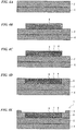
- strain sensor 1 It is possible to manufacture the strain sensor 1 according to the following manufacturing processes.
- the resin layer 7 is preferably not impregnated into the inner portion of the CNT fiber bundles.
- the resin layer 7 is preferably formed using an aqueous emulsion.
- an aqueous emulsion in the formation of the resin layer in the way, it is possible to form the resin layer that covers the periphery of the CNT fiber bundles easily and reliably by for example coating or immersion without impregnating it into the CNT fiber bundles.
- the CNT fiber bundles 6 have connection portions at which the CNT fibers connect with each other in the longitudinal direction. In this way, by using the CNT fiber bundles in which CNT fibers are connected to each other in the longitudinal direction, it is possible to favorably use the strain sensor with excellent linearity in its resistance change for various uses.
- the plurality of CNT fiber bundles 6 preferably have break places in the longitudinal direction.
- the CNT fiber bundles having break places in the longitudinal direction (orientation direction) in this manner since the resistance change of the strain sensor is imparted by changes in the interval (gap) of these break places chiefly during extension and contraction of the strain sensor, it is possible to further increase the linearity of the resistance change and responsiveness of the strain sensor, and increase the reproducibility of the resistance change.
- the CNT fiber bundle has the impregnated portion, the bonding force between the CNT film and the substrate, and the strength of the CNT film are increased. Because the CNT fiber bundle also has the non-impregnated portion, it is possible to prevent deformation in the orientation direction of the CNT fiber bundle from being impeded by the resin, so that it is possible to further increase the sensitivity of the strain sensor and the linearity of the resistance change. Also, since spaces are readily formed in the CNT fiber bundle, it is possible to further improve the responsiveness of the sensor. Further, rupture of the CNT fiber bundle 6 can be induced in accordance with a degree of an amount of resin impregnated to the peripheral layer of the CNT fiber bundle 6. In this respect, the responsiveness of the strain sensor 1 can be increased. This operation changes the distribution or gradation of the CNT fibers so that the distribution or gradation changes can be observed by a microscope.
- a strain sensor 11 of FIG. 7 is mainly provided with the substrate 2, the pair of electrodes 3, the CNT film 4, and an assist layer 8 that is laminated on the back surface of the substrate 2.
- the substrate 2, the electrodes 3 and the CNT film 4 are the same as the strain sensor 1 shown in FIG. 1A to 1C , so they shall be given the same reference numerals, and their explanation shall be omitted.
- the assist layer 8 is a material with a different Young's modulus than the substrate 2.
- This assist layer 8 be a member with a lower Young's modulus than the substrate 2, it is possible to enhance the following performance in the case of directly affixing the strain sensor 11 to skin or the like.
- the material of the assist layer 8 in accordance with the design conditions of the Young's modulus, and besides the synthetic resin or rubber and the like illustrated above, it is possible to use a woven fabric, non-woven fabrics or knit as the material of the substrate 2.
- a knit as the assist layer 8 it is possible to entirely or partially impregnate the substrate in the fiber layer of the knit. By doing so, the bonding strength between the knit and the substrate 2 increases, and moreover the knit plays a role of inhibiting full extension of the strain sensor 11.
- By arranging a knit in this way on the backmost surface side it is possible to achieve a strain sensor that is suited to being affixed to clothing and the like, and that has a good detection sensitivity.
- the upper limit of the ratio of the Young's modulus of the assist layer 8 with respect to the Young's modulus of the substrate 2 is preferably 0.9, and more preferably 0.7.
- the ratio of Young's moduli exceeds the upper limit, there is a risk of the following performance enhancement effect by the assist layer 8 with respect to movement of the body on which the strain sensor is affixed not being sufficiently obtained.
- the lower limit of the ratio of the Young's modulus of the assist layer 8 with respect to the Young's modulus of the substrate 2 is preferably 0.4, and more preferably 0.5. When the ratio of Young's moduli is less than the lower limit, there is a risk that the assist layer 8 and the substrate 2 may easily exfoliate due to extension and contraction.
- the upper limit of the ratio of the Young's modulus of the assist layer 8 with respect to the Young's modulus of the substrate 2 is preferably 2.5, and more preferably 2.0.
- the lower limit of the ratio of the Young's modulus of the assist layer 8 with respect to the Young's modulus of the substrate 2 is preferably 1.1, and more preferably 1.5.
- the average thickness of the assist layer 8 is not particularly limited, it is possible to make it for example between 10 ⁇ m and 1,000 ⁇ m.
- the strain sensor 11 similarly to the strain sensor 1 of the first embodiment, is capable of inhibiting the occurrence of contamination of the CNT film 4 by foreign substances and enhancing the durability of the sensor function while improving the linearity of the resistance change and responsiveness by the plurality of CNT fiber bundles 6 that are oriented in the longitudinal direction A and the resin layer 7 that covers them.
- the assist layer 8 it is possible with the assist layer 8 to enhance the following performance with respect to movement of the body on which the strain sensor is affixed, and the detection sensitivity.
- a strain sensor 21 of FIG. 8 is mainly provided with the substrate 2, the pair of electrodes 3, the CNT film 4, and an assist layer 9 that is laminated on the surface of the CNT film 4.
- the substrate 2, the electrodes 3 and the CNT film 4 are the same as the strain sensor 1 shown in FIG. 1A to 1C , so they shall be given the same reference numerals, and their explanation shall be omitted.
- the assist layer 9 may be the same as the one in the strain sensor 11 of FIG. 11 . Note that the assist layer 9 preferably also covers the conductive layer 5 as shown in FIG. 8 .
- the assist layer 9 laminated on the surface of the CNT film 4 it is possible by means of the assist layer 9 laminated on the surface of the CNT film 4 to improve the following performance of the strain sensor 21 with respect to movement of the body on which the strain sensor is affixed and also its detection sensitivity. Also, it is possible to more reliably prevent contamination of the CNT film 4 by foreign substances.
- the assist layers may be provided on both sides of the strain sensor.
- this strain sensor By mounting this strain sensor on the chest of a human body, it is possible to detect the breathing of the wearer. As stated above, since this strain sensor has high linearity and responsiveness, even when the wearer is physically active it can detect the person's breathing with high accuracy by following the movements of the chest. Note that when mounting this strain sensor on the chest with the purpose of detecting breathing in this way, it is preferred to mount it in the vicinity of the solar plexus so that the orientation direction of the CNT fibers matches the chest circumference direction (left-right direction).
- this strain sensor by mounting this strain sensor on a finger of a human body, it can detect movements of the finger. For example, by mounting this strain sensor at the base of a finger so that the orientation direction of the CNT fibers is perpendicular to the bending direction of the finger, it is possible to sense changes in the girth of the finger, and possible to detect the state and degree of strength of the finger.
- assist layers may be provided on each of the back surface of the substrate and the surface of the CNT film of the strain sensor.
- the CNT film may have a portion capable of cleaving along a direction perpendicular with the orientation of the CNT fiber bundles.
- the strain sensor 31 shown in FIG. 9 two CNT films 4 are arranged side by side to be parallel in the longitudinal direction (CNT fiber orientation direction), and one end of each of these CNT films 4 is connected by the conductive layer 5 in a direction perpendicular with the longitudinal direction.
- the electrode 3 is not provided at the connection side of the CNT films 4, and instead electrodes 3 that connect with each CNT film 4 are separately provided at the opposite side of the connection side.
- the orientation of the CNT fibers changes by 180° at the conductive layer 5
- the pair of electrodes 3 are arranged in a prescribed manner at both ends in the orientation direction of the CNT fibers.
- this strain sensor 31 it is possible to double the orientation length of the CNT fibers that the CNT film 4 has, while maintaining the length in the longitudinal direction as is. It is also possible to connect three or more CNT films 4 in the direction perpendicular with the longitudinal direction by the conductive layer 5.
- the substrate of the strain sensor is not limited to the plate-shaped body consisting of a perfect rectangular parallelepiped, and it is possible to use one that is deformed.
- the CNT fiber bundles may also use CNT fibers that are obtained by spinning CNT.
- another pair of facing electrodes may be provided in a direction perpendicular with the facing direction of the pair of electrodes. By providing two pairs of electrodes that are orthogonal in this way, it is possible to use this strain sensor as a two-dimensional sensor.
- by covering the front and back surface of the strain sensor with a resin having adhesiveness it can be also be used by being easily affixed to locations of a human body or structure where strain is to be measured.
- FIGS. 10A and 10B The change in resistance of the strain sensor was measured when applying a tensile force in the orientation direction A of the CNT fibers to the strain sensor shown in FIGS. 1A to 1C , and periodically altering the strain amount (extension with respect to the A direction length of the strain sensor) between 25% and 80% at a period of 3 Hz.
- FIGS. 10A and 10B The results are shown in FIGS. 10A and 10B.
- FIG. 10A is a graph that shows the response reactivity, which plots changes in the strain amount and the resistance value over 1 sec.
- FIG. 10B is a graph that plots the relation between the strain amount and the resistance value in FIG. 10A .
- FIGS. 11A and 11B are graphs that shows the response reactivity, which plots changes in the strain amount and the resistance value over 1 sec.
- FIG. 11B is a graph that plots the relation between the strain amount and the resistance value in FIG. 11A .
- the strain sensor of the present invention has excellent responsiveness, with the delay in the response to changes in the resistance value with respect to changes in the strain amount being extremely small.
- the relation between the strain amount and the resistance value maintains an approximate line shape, and the linearity of the resistance change and durability are found to be excellent.
- the resistance value changes in a linear manner and it provides excellent responsiveness.
- the strain sensor of the present invention is capable of inhibiting the occurrence of contamination of the CNT film by foreign substances and enhancing the durability of the sensor function while improving the linearity of the resistance change and responsiveness.
Landscapes
- Chemical & Material Sciences (AREA)
- Engineering & Computer Science (AREA)
- Physics & Mathematics (AREA)
- General Physics & Mathematics (AREA)
- Nanotechnology (AREA)
- Composite Materials (AREA)
- Condensed Matter Physics & Semiconductors (AREA)
- Materials Engineering (AREA)
- Crystallography & Structural Chemistry (AREA)
- Measurement Of Length, Angles, Or The Like Using Electric Or Magnetic Means (AREA)
- Investigating Or Analyzing Materials By The Use Of Electric Means (AREA)
- Carbon And Carbon Compounds (AREA)
Claims (12)
- Dehnungssensor umfassend:ein über Flexibilität verfügendes Substrat;einen Kohlenstoffnanoröhrenfilm (CNT), der auf der Oberfläche des Substrats bereitgestellt ist und über eine Vielzahl von CNT-Fasern verfügt, die in einer Richtung orientiert sind; undein an beiden Enden des CNT-Films in Orientierungsrichtung der CNT-Fasern angeordnetes Elektrodenpaar;wobei der CNT-Film eine Vielzahl von CNT-Faserbündeln aufweist, die aus einer Vielzahl von CNT-Fasern bestehen, sowie eine Harzschicht, welche die Umfangsfläche der Vielzahl von CNT-Faserbündeln bedeckt und mit der Oberfläche des Substrats verbindet; undwobei die CNT-Faserbündel in einer Ausdehnungs- und Kontraktionsrichtung des Dehnungssensors orientiert sind.
- Dehnungssensor nach Anspruch 1, wobei die Harzschicht nicht in den CNT-Faserbündeln imprägniert ist.
- Dehnungssensor nach Anspruch 2, wobei die Harzschicht aus einer wässrigen Emulsion gebildet ist.
- Dehnungssensor nach einem der Ansprüche 1 bis 3, wobei die CNT-Faserbündel Verbindungsteile aufweisen, an denen die CNT-Fasern in Längsrichtung miteinander verbunden sind.
- Dehnungssensor nach einem der Ansprüche 1 bis 4, wobei die Vielzahl von CNT-Faserbündeln Bruchstellen in Längsrichtung aufweist.
- Dehnungssensor nach einem der Ansprüche 1 bis 4, wobei der CNT-Film eine durchschnittliche Stärke von zwischen 0,1 µm und 50 µm aufweist.
- Dehnungssensor nach Anspruch 1, wobei die CNT-Faserbündel einen imprägnierten Teil einschließen, der mit der Harzschicht imprägniert ist, und einen nichtimprägnierten Teil, der von dem imprägnierten Teil umwickelt und nicht mit der Harzschicht imprägniert ist.
- Verfahren zur Herstellung eines Dehnungssensors, das folgende Schritte umfasst:Anordnen eines Kohlenstoffnanoröhrenfilms (CNT), der eine Vielzahl von CNT-Faserbündeln bestehend aus einer Vielzahl von in einer Richtung orientierten CNT-Fasern aufweist, auf der Oberfläche eines über Flexibilität verfügenden Substrats;Bilden eines Elektrodenpaares an beiden Enden des CNT-Films in der Orientierungsrichtung der CNT-Fasern; undBilden einer Harzschicht im CNT-Film, um die Umfangsfläche der Vielzahl von CNT-Faserbündeln zu bedecken und eng an der Oberfläche des Substrats anzuliegen,wobei die CNT-Faserbündel in einer Ausdehnungs- und Kontraktionsrichtung des Dehnungssensors orientiert sind.
- Verfahren zur Herstellung eines Dehnungssensors nach Anspruch 8, wobei der Schritt des Bildens der Harzschicht im CNT-Film einen Schritt einschließt, bei dem eine wässrige Emulsion auf den CNT-Film aufgetragen wird, die Harz aufweist, welches als das dispergierte Material zur Harzschicht wird.
- Verfahren zur Herstellung eines Dehnungssensors nach Anspruch 9, wobei der CNT-Film eine Stärke von zwischen 0,1 µm und 50 µm aufweist.
- Verfahren zur Herstellung eines Dehnungssensors nach Anspruch 8, wobei der Schritt des Bildens der Harzschicht im CNT-Film einen Schritt einschließt, bei dem der auf der Oberfläche des Substrats angeordnete CNT-Film in eine wässrige Emulsion getaucht wird, die Harz aufweist, welches als das dispergierte Material zur Harzschicht wird.
- Verfahren zur Herstellung eines Dehnungssensors nach einem der Ansprüche 8 bis 11, wobei nach dem Schritt des Anordnens des CNT-Films auf der Oberfläche des Substrats der CNT-Film in Orientierungsrichtung der CNT-Fasern gedehnt wird, um Bruchstellen an zufälligen Orten innerhalb der CNT-Faserbündel zu bilden.
Applications Claiming Priority (2)
| Application Number | Priority Date | Filing Date | Title |
|---|---|---|---|
| JP2013100751 | 2013-05-10 | ||
| JP2014002044 | 2014-01-08 |
Publications (2)
| Publication Number | Publication Date |
|---|---|
| EP2801549A1 EP2801549A1 (de) | 2014-11-12 |
| EP2801549B1 true EP2801549B1 (de) | 2018-01-31 |
Family
ID=50678052
Family Applications (1)
| Application Number | Title | Priority Date | Filing Date |
|---|---|---|---|
| EP14167525.6A Active EP2801549B1 (de) | 2013-05-10 | 2014-05-08 | Dehnungssensor basierend auf Kohlenstoff-Nanoröhren und Verfahren zu dessen Herstellung |
Country Status (4)
| Country | Link |
|---|---|
| US (1) | US9476782B2 (de) |
| EP (1) | EP2801549B1 (de) |
| JP (1) | JP6014906B2 (de) |
| CN (1) | CN104142118B (de) |
Cited By (1)
| Publication number | Priority date | Publication date | Assignee | Title |
|---|---|---|---|---|
| US10571326B2 (en) | 2015-08-07 | 2020-02-25 | Extron Company | System for sensing substance levels in a storage unit |
Families Citing this family (42)
| Publication number | Priority date | Publication date | Assignee | Title |
|---|---|---|---|---|
| US9618403B2 (en) * | 2013-10-02 | 2017-04-11 | Florida State University Research Foundation, Inc. | Strain sensors and methods of manufacture and use |
| US9752918B2 (en) | 2014-08-04 | 2017-09-05 | Extron Company | System for sensing flowable substrate levels in a storage unit |
| JP6470049B2 (ja) * | 2015-01-19 | 2019-02-13 | ヤマハ株式会社 | 糸状歪みセンサ素子及び布帛状歪みセンサ素子 |
| WO2016136685A1 (ja) * | 2015-02-23 | 2016-09-01 | リンテック オブ アメリカ インク | 粘着シート |
| JP2016176874A (ja) * | 2015-03-20 | 2016-10-06 | ヤマハ株式会社 | 歪みセンサ素子 |
| US10020439B2 (en) * | 2015-05-28 | 2018-07-10 | Honda Motor Co., Ltd. | Electrostrictive element |
| US10020440B2 (en) * | 2015-05-28 | 2018-07-10 | Honda Motor Co., Ltd. | Electrostrictive element and manufacturing method therefor |
| CN104880206B (zh) * | 2015-06-09 | 2018-03-06 | 中国科学院深圳先进技术研究院 | 电阻应变片及电阻应变式传感器 |
| JP6561636B2 (ja) * | 2015-07-09 | 2019-08-21 | ヤマハ株式会社 | 歪みセンサ素子 |
| FR3038710B1 (fr) | 2015-07-10 | 2021-05-28 | Cpc Tech | Capteur d'une caracteristique physique, comportant de preference une structure multicouches |
| FR3039272B1 (fr) * | 2015-07-22 | 2019-05-17 | Commissariat A L'energie Atomique Et Aux Energies Alternatives | Jauge de deformation et son procede de fabrication |
| WO2017038384A1 (ja) * | 2015-08-28 | 2017-03-09 | ヤマハ株式会社 | 歪みセンサ素子の製造方法及び歪みセンサ素子 |
| JP6625877B2 (ja) * | 2015-12-08 | 2019-12-25 | ヤマハ株式会社 | 導電体、歪みセンサー、及び導電体の製造方法 |
| JP6597318B2 (ja) * | 2016-01-06 | 2019-10-30 | ヤマハ株式会社 | 歪みセンサ素子 |
| JP6759689B2 (ja) * | 2016-05-10 | 2020-09-23 | ヤマハ株式会社 | 歪みセンサユニット |
| CN106152930A (zh) * | 2016-06-24 | 2016-11-23 | 北京科技大学 | 一种高灵敏柔性可穿戴应变传感器及其低成本制作方法 |
| CN107726971A (zh) * | 2016-08-11 | 2018-02-23 | 清华大学 | 应变传感器 |
| US11073385B2 (en) | 2016-11-17 | 2021-07-27 | King Abdullah University Of Science And Technology | Devices and methods relating to fragmented carbon nanotube sensors |
| CN106643464B (zh) * | 2016-12-27 | 2019-02-22 | 北京航空航天大学 | 一种基于碳纳米管膜的复合材料各向应变监测方法 |
| CN111527245B (zh) * | 2017-12-01 | 2023-05-09 | 华盛顿大学 | 具有断裂感应机电灵敏度的纤维基复合材料 |
| CN108106639A (zh) * | 2017-12-08 | 2018-06-01 | 合肥鑫晟光电科技有限公司 | 一种柔性传感器及其制备方法 |
| KR102668688B1 (ko) | 2018-07-23 | 2024-05-24 | 삼성디스플레이 주식회사 | 유기 발광 소자 |
| RU2685570C1 (ru) * | 2018-10-10 | 2019-04-22 | Федеральное государственное автономное образовательное учреждение высшего образования "Национальный исследовательский университет "Московский институт электронной техники" | Униполярный датчик деформации |
| CN109520409A (zh) * | 2018-10-28 | 2019-03-26 | 北京工业大学 | 一种基于cnt纤维力阻性能制作的柔性应变传感器及实验方法 |
| CN109631742B (zh) * | 2018-12-25 | 2020-10-02 | 东南大学 | 一种基于碳纳米管的柔性应变传感器及其制备方法 |
| KR102661468B1 (ko) | 2019-02-15 | 2024-04-30 | 삼성디스플레이 주식회사 | 유기 발광 소자 및 이를 포함한 전자 장치 |
| CN109916292B (zh) * | 2019-02-25 | 2021-05-04 | 武汉工程大学 | 一种多层电容式柔性智能可穿戴传感器件的制备方法 |
| US10801827B1 (en) | 2019-05-03 | 2020-10-13 | At&T Intellectual Property I, L.P. | Sensor based on smart response of two-dimensional nanomaterial and associated method |
| KR102897919B1 (ko) | 2019-11-14 | 2025-12-09 | 삼성디스플레이 주식회사 | 유기 발광 소자 및 이를 포함한 장치 |
| JP2021079644A (ja) * | 2019-11-20 | 2021-05-27 | 凸版印刷株式会社 | 印刷物とその製造方法、及び圧力感知シート |
| CN110906858B (zh) * | 2019-12-03 | 2022-04-19 | 观云(山东)智能科技有限公司 | 一种无纺复合材料、结构应变传感器、分布式监测系统及方法 |
| KR102776384B1 (ko) | 2020-05-06 | 2025-03-10 | 삼성디스플레이 주식회사 | 발광 소자 및 이를 포함하는 전자 장치 |
| CN111586945B (zh) * | 2020-05-29 | 2023-04-21 | 福建星宏新材料科技有限公司 | 单键触压调光开关 |
| CN111829700A (zh) * | 2020-07-21 | 2020-10-27 | 重庆交通大学 | 用于碳纳米纤维增强沥青电阻应力检测的半导体传感纤维、纤维界面传感装置及其检测方法 |
| CN112161738B (zh) * | 2020-09-17 | 2022-04-08 | 五邑大学 | 气压传感器及制作方法 |
| CN114087976B (zh) * | 2021-11-25 | 2023-04-07 | 中国科学院长春应用化学研究所 | 一种柔性大应变传感器及其制备方法 |
| CN116558701A (zh) * | 2022-01-28 | 2023-08-08 | 复旦大学 | 兼具高灵敏度及高精度的场发射柔性压力传感薄膜及其制备方法 |
| CN114739354B (zh) * | 2022-03-25 | 2023-11-14 | 广东技术师范大学 | 一种应变传感器及其制备方法 |
| CN115824031B (zh) * | 2022-12-13 | 2026-01-09 | 陕西科技大学 | 一种各向异性柔性应变传感器及其制备方法和应用 |
| WO2024231950A1 (en) * | 2023-05-10 | 2024-11-14 | NoPo Nanotechnologies India Private Limited | A fast response carbon nanotubes stretch sensor |
| WO2026004983A1 (ja) * | 2024-06-28 | 2026-01-02 | 学校法人順天堂 | 呼吸センサ |
| US20260047778A1 (en) * | 2024-08-13 | 2026-02-19 | Growth Armor, LLC | Systems and methods for monitoring body orientation of a subject |
Family Cites Families (59)
| Publication number | Priority date | Publication date | Assignee | Title |
|---|---|---|---|---|
| JPS62200701A (ja) | 1986-02-28 | 1987-09-04 | 旭化成株式会社 | 変形導電性編物 |
| US6655218B1 (en) | 1999-05-28 | 2003-12-02 | Fuji Jukogyo Kabushiki Kaisha | Composite material and method of controlling damage thereto and damage sensor |
| DE10144269A1 (de) | 2001-09-08 | 2003-03-27 | Bosch Gmbh Robert | Sensorelement zur Erfassung einer physikalischen Messgröße zwischen tribologisch hoch beanspruchten Körpern |
| DE10144271A1 (de) | 2001-09-08 | 2003-03-27 | Bosch Gmbh Robert | Sensorelement zur Erfassung einer physikalischen Messgröße zwischen tribologisch hoch beanspruchten Körpern |
| JP3924472B2 (ja) | 2002-02-05 | 2007-06-06 | 株式会社ジェイテクト | カーボンナノチューブを用いたセンサ |
| US20080021339A1 (en) | 2005-10-27 | 2008-01-24 | Gabriel Jean-Christophe P | Anesthesia monitor, capacitance nanosensors and dynamic sensor sampling method |
| JP4685356B2 (ja) | 2002-04-19 | 2011-05-18 | 旭化成エレクトロニクス株式会社 | 磁電変換素子及びその製造方法 |
| JP4547852B2 (ja) * | 2002-09-04 | 2010-09-22 | 富士ゼロックス株式会社 | 電気部品の製造方法 |
| AU2003287681A1 (en) | 2002-11-15 | 2004-06-15 | Meguiar's, Inc. | Protective coating compositions, systems, and methods |
| US7730547B2 (en) | 2003-01-23 | 2010-06-01 | William Marsh Rice University | Smart materials: strain sensing and stress determination by means of nanotube sensing systems, composites, and devices |
| JP4192713B2 (ja) | 2003-07-25 | 2008-12-10 | 富士ゼロックス株式会社 | アリールアミン化合物、電荷輸送材料、電子写真感光体、画像形成装置及びプロセスカートリッジ |
| US20050036905A1 (en) | 2003-08-12 | 2005-02-17 | Matsushita Electric Works, Ltd. | Defect controlled nanotube sensor and method of production |
| US7325456B2 (en) | 2003-09-22 | 2008-02-05 | Hyeung-Yun Kim | Interrogation network patches for active monitoring of structural health conditions |
| US7536912B2 (en) | 2003-09-22 | 2009-05-26 | Hyeung-Yun Kim | Flexible diagnostic patches for structural health monitoring |
| AU2004277167A1 (en) | 2003-09-22 | 2005-04-07 | Kim Hyeung-Yun | Methods for monitoring structural health conditions |
| US20050209392A1 (en) | 2003-12-17 | 2005-09-22 | Jiazhong Luo | Polymer binders for flexible and transparent conductive coatings containing carbon nanotubes |
| JP2005223107A (ja) | 2004-02-05 | 2005-08-18 | Hitachi Ltd | 電界効果型トランジスタ及びその製造方法 |
| US20050260412A1 (en) | 2004-05-19 | 2005-11-24 | Lockheed Martin Corporation | System, method, and apparatus for producing high efficiency heat transfer device with carbon nanotubes |
| US7378040B2 (en) | 2004-08-11 | 2008-05-27 | Eikos, Inc. | Method of forming fluoropolymer binders for carbon nanotube-based transparent conductive coatings |
| US8926933B2 (en) | 2004-11-09 | 2015-01-06 | The Board Of Regents Of The University Of Texas System | Fabrication of twisted and non-twisted nanofiber yarns |
| US7750434B2 (en) | 2005-01-31 | 2010-07-06 | Sanyo Electric Co., Ltd. | Circuit substrate structure and circuit apparatus |
| JP4492416B2 (ja) * | 2005-04-07 | 2010-06-30 | パナソニック電工株式会社 | 物理量センサ |
| JP4591222B2 (ja) | 2005-06-09 | 2010-12-01 | セイコーエプソン株式会社 | 電気光学装置及び画像形成装置 |
| US7278324B2 (en) * | 2005-06-15 | 2007-10-09 | United States Of America As Represented By The Administrator Of The National Aeronautics And Space Administration | Carbon nanotube-based sensor and method for detection of crack growth in a structure |
| JP4983150B2 (ja) | 2006-04-28 | 2012-07-25 | 東洋インキScホールディングス株式会社 | 導電性被膜の製造方法 |
| NZ563934A (en) | 2006-05-02 | 2012-06-29 | Whiteley Corp Pty Ltd | Safety coatings |
| US8535791B2 (en) | 2006-06-30 | 2013-09-17 | The University Of Akron | Aligned carbon nanotube-polymer materials, systems and methods |
| CN100420626C (zh) | 2006-11-27 | 2008-09-24 | 西南交通大学 | 纯碳纳米管薄膜的制备方法 |
| US7817333B2 (en) | 2007-02-06 | 2010-10-19 | Photon Dynamics, Inc. | Modulator with improved sensitivity and life time |
| WO2008111653A1 (ja) | 2007-03-14 | 2008-09-18 | Taiyo Nippon Sanso Corporation | ブラシ状カーボンナノ構造物製造用触媒体、触媒体製造方法、ブラシ状カーボンナノ構造物及びその製法 |
| ES2307423B1 (es) * | 2007-05-04 | 2009-09-22 | Antonio Miravete De Marco | Sistema de monitorizacion del daño en estructuras mediante sensores denanocomposite. |
| US7500399B2 (en) | 2007-07-02 | 2009-03-10 | The Hong Kong Polytechnic University | Piezoresistive strain gauge using doped polymeric fluid |
| CN101121859A (zh) | 2007-09-21 | 2008-02-13 | 东华大学 | 具有抑菌功效的水性环氧树脂涂料及其制备方法 |
| KR20080012393A (ko) | 2008-01-17 | 2008-02-11 | 김재호 | 고 내마모성 및 고 투명성의 수용성 광경화형 대전방지조성물 및 이를 코팅한 전도성 타일 바닥재 |
| JP2009189747A (ja) * | 2008-02-18 | 2009-08-27 | Goto Ikueikai | 歪センサ |
| JP2009216939A (ja) | 2008-03-10 | 2009-09-24 | Fuji Xerox Co Ltd | 電子写真用トナー及びその製造方法、電子写真用現像剤、トナーカートリッジ、プロセスカートリッジ、画像形成装置 |
| US8946848B2 (en) | 2008-06-05 | 2015-02-03 | Omnivision Technologies, Inc. | Apparatus and method for image sensor with carbon nanotube based transparent conductive coating |
| WO2010005707A1 (en) | 2008-06-16 | 2010-01-14 | The Board Of Trustees Of The University Of Illinois | Medium scale carbon nanotube thin film integrated circuits on flexible plastic substrates |
| JP2010047702A (ja) | 2008-08-22 | 2010-03-04 | Toho Chem Ind Co Ltd | 耐汚染性、透明性、光沢性に優れた帯電防止性熱可塑性樹脂組成物 |
| JP5299616B2 (ja) | 2008-10-23 | 2013-09-25 | 富士ゼロックス株式会社 | 静電荷像現像用トナー及びその製造方法、静電荷像現像剤、トナーカートリッジ、プロセスカートリッジ、画像形成方法、並びに、画像形成装置 |
| US7854173B2 (en) | 2008-11-28 | 2010-12-21 | The Hong Kong Polytechnic University | Strain sensor |
| US8038479B2 (en) | 2008-12-05 | 2011-10-18 | Nanoridge Materials | Carbon nanotube-based electrical connectors |
| JP2010224503A (ja) | 2009-03-25 | 2010-10-07 | Fuji Xerox Co Ltd | 電子写真感光体、画像形成装置及びプロセスカートリッジ |
| CN101570662B (zh) | 2009-03-26 | 2010-10-27 | 天津大学 | 金属膜电阻器用耐高温、耐高湿涂料及其制备方法 |
| US9732238B2 (en) * | 2009-05-14 | 2017-08-15 | Battelle Memorial Institute | Solventless methods of coating a carbon nanotube network and carbon nanotube networks coated with a polymer |
| US8519449B2 (en) | 2009-08-25 | 2013-08-27 | Honeywell International Inc. | Thin-film transistor based piezoelectric strain sensor and method |
| JP5397896B2 (ja) * | 2009-08-25 | 2014-01-22 | 独立行政法人産業技術総合研究所 | カーボンナノチューブを用いた伸縮装置、伸縮駆動装置およびcnt膜構造体 |
| US8471438B2 (en) | 2009-08-27 | 2013-06-25 | Canon Kabushiki Kaisha | Actuator with sensor |
| US8299686B2 (en) | 2009-08-27 | 2012-10-30 | Canon Kabushiki Kaisha | Actuator with sensor |
| CN101672619A (zh) | 2009-09-29 | 2010-03-17 | 武汉理工大学 | 碳纤维搭接式应变传感器 |
| US8187887B2 (en) | 2009-10-06 | 2012-05-29 | Massachusetts Institute Of Technology | Method and apparatus for determining radiation |
| US8518472B2 (en) | 2010-03-04 | 2013-08-27 | Guardian Industries Corp. | Large-area transparent conductive coatings including doped carbon nanotubes and nanowire composites, and methods of making the same |
| CN101859216B (zh) | 2010-06-11 | 2012-01-25 | 北京富纳特创新科技有限公司 | 触摸屏 |
| US8564954B2 (en) | 2010-06-15 | 2013-10-22 | Chipmos Technologies Inc. | Thermally enhanced electronic package |
| US9233492B2 (en) * | 2010-10-12 | 2016-01-12 | Florida State University Research Foundation, Inc. | Composite materials reinforced with carbon nanotube yarns |
| CN102095362A (zh) * | 2010-11-20 | 2011-06-15 | 武汉理工大学 | 栅型碳纤维应变传感器 |
| US20120282453A1 (en) * | 2011-05-05 | 2012-11-08 | North Carolina State University | Carbon nanotube composites and methods and apparatus for fabricating same |
| JP5924725B2 (ja) * | 2011-11-14 | 2016-05-25 | ヤマハ株式会社 | 歪みセンサ及び歪みセンサの製造方法 |
| CN202329535U (zh) * | 2011-11-22 | 2012-07-11 | 东南大学 | 一种分布式高精度长标距碳纤维应变测试装置 |
-
2014
- 2014-05-08 EP EP14167525.6A patent/EP2801549B1/de active Active
- 2014-05-08 CN CN201410192680.1A patent/CN104142118B/zh active Active
- 2014-05-08 JP JP2014097218A patent/JP6014906B2/ja active Active
- 2014-05-09 US US14/274,305 patent/US9476782B2/en active Active
Non-Patent Citations (1)
| Title |
|---|
| None * |
Cited By (3)
| Publication number | Priority date | Publication date | Assignee | Title |
|---|---|---|---|---|
| US10571326B2 (en) | 2015-08-07 | 2020-02-25 | Extron Company | System for sensing substance levels in a storage unit |
| US10996097B2 (en) | 2015-08-07 | 2021-05-04 | Extron Company | System for sensing substance levels in a storage unit |
| US11579005B2 (en) | 2015-08-07 | 2023-02-14 | Extron Company | System for sensing substance levels in a storage unit |
Also Published As
| Publication number | Publication date |
|---|---|
| JP6014906B2 (ja) | 2016-10-26 |
| CN104142118B (zh) | 2017-07-07 |
| JP2015148588A (ja) | 2015-08-20 |
| CN104142118A (zh) | 2014-11-12 |
| EP2801549A1 (de) | 2014-11-12 |
| US20140331793A1 (en) | 2014-11-13 |
| US9476782B2 (en) | 2016-10-25 |
Similar Documents
| Publication | Publication Date | Title |
|---|---|---|
| EP2801549B1 (de) | Dehnungssensor basierend auf Kohlenstoff-Nanoröhren und Verfahren zu dessen Herstellung | |
| JP5924725B2 (ja) | 歪みセンサ及び歪みセンサの製造方法 | |
| KR102089604B1 (ko) | 복합 나노섬유 시트 | |
| JP2014038088A (ja) | 歪みセンサ | |
| JP5044196B2 (ja) | 圧電センサ及びその製造方法 | |
| JP6701748B2 (ja) | 歪みセンサ素子 | |
| CN109073353B (zh) | 应变传感器单元 | |
| JP2017106129A (ja) | 導電体、歪みセンサー、及び導電体の製造方法 | |
| US10816317B2 (en) | Strain sensor element | |
| JP6488698B2 (ja) | 外力検出アレイモジュール | |
| CN107787255B (zh) | 换能器转移堆叠体 | |
| JP6561636B2 (ja) | 歪みセンサ素子 | |
| JP2016176874A (ja) | 歪みセンサ素子 | |
| JP7388412B2 (ja) | 歪みセンサ素子の製造方法及び歪みセンサ素子 | |
| JP6821949B2 (ja) | 歪みセンサユニット | |
| JP2017020872A (ja) | 歪みセンサ素子 | |
| MXPA02007741A (es) | Antena de electrodo flexible. | |
| JP2017211214A (ja) | 歪みセンサ及び歪みセンサユニット | |
| JP6161041B2 (ja) | 歪みセンサ及び歪みセンサの製造方法 | |
| US10697753B2 (en) | Strain sensing device and manufacturing method thereof | |
| KR20150089362A (ko) | 진공 단열재 및 이의 제조방법 | |
| JP2016176875A (ja) | 歪みセンサ及び電極 | |
| JP2000214006A5 (de) | ||
| KR20180091251A (ko) | 탄소나노물질 테이프를 이용한 스트레인 센서 및 이의 제조방법 |
Legal Events
| Date | Code | Title | Description |
|---|---|---|---|
| PUAI | Public reference made under article 153(3) epc to a published international application that has entered the european phase |
Free format text: ORIGINAL CODE: 0009012 |
|
| 17P | Request for examination filed |
Effective date: 20140508 |
|
| AK | Designated contracting states |
Kind code of ref document: A1 Designated state(s): AL AT BE BG CH CY CZ DE DK EE ES FI FR GB GR HR HU IE IS IT LI LT LU LV MC MK MT NL NO PL PT RO RS SE SI SK SM TR |
|
| AX | Request for extension of the european patent |
Extension state: BA ME |
|
| R17P | Request for examination filed (corrected) |
Effective date: 20150511 |
|
| RBV | Designated contracting states (corrected) |
Designated state(s): AL AT BE BG CH CY CZ DE DK EE ES FI FR GB GR HR HU IE IS IT LI LT LU LV MC MK MT NL NO PL PT RO RS SE SI SK SM TR |
|
| GRAP | Despatch of communication of intention to grant a patent |
Free format text: ORIGINAL CODE: EPIDOSNIGR1 |
|
| RIC1 | Information provided on ipc code assigned before grant |
Ipc: G01L 1/24 20060101ALI20170718BHEP Ipc: G01B 7/16 20060101ALI20170718BHEP Ipc: B82Y 30/00 20110101AFI20170718BHEP Ipc: G01L 1/22 20060101ALI20170718BHEP |
|
| INTG | Intention to grant announced |
Effective date: 20170814 |
|
| GRAS | Grant fee paid |
Free format text: ORIGINAL CODE: EPIDOSNIGR3 |
|
| GRAA | (expected) grant |
Free format text: ORIGINAL CODE: 0009210 |
|
| RAP1 | Party data changed (applicant data changed or rights of an application transferred) |
Owner name: YAMAHA CORPORATION Owner name: NATIONAL UNIVERSITY CORPORATION SHIZUOKA UNIVERSIT |
|
| AK | Designated contracting states |
Kind code of ref document: B1 Designated state(s): AL AT BE BG CH CY CZ DE DK EE ES FI FR GB GR HR HU IE IS IT LI LT LU LV MC MK MT NL NO PL PT RO RS SE SI SK SM TR |
|
| REG | Reference to a national code |
Ref country code: GB Ref legal event code: FG4D Ref country code: CH Ref legal event code: EP |
|
| REG | Reference to a national code |
Ref country code: AT Ref legal event code: REF Ref document number: 967185 Country of ref document: AT Kind code of ref document: T Effective date: 20180215 |
|
| REG | Reference to a national code |
Ref country code: IE Ref legal event code: FG4D |
|
| RIN2 | Information on inventor provided after grant (corrected) |
Inventor name: SUZUKI, KATSUNORI Inventor name: YATAKA, KOJI Inventor name: INOUE, YOKU Inventor name: OKUMIYA, YASURO Inventor name: SAKAKIBARA, SHINGO Inventor name: SUGIURA, MASAHIRO |
|
| REG | Reference to a national code |
Ref country code: DE Ref legal event code: R096 Ref document number: 602014020254 Country of ref document: DE |
|
| REG | Reference to a national code |
Ref country code: NL Ref legal event code: MP Effective date: 20180131 |
|
| REG | Reference to a national code |
Ref country code: LT Ref legal event code: MG4D |
|
| REG | Reference to a national code |
Ref country code: AT Ref legal event code: MK05 Ref document number: 967185 Country of ref document: AT Kind code of ref document: T Effective date: 20180131 |
|
| PG25 | Lapsed in a contracting state [announced via postgrant information from national office to epo] |
Ref country code: LT Free format text: LAPSE BECAUSE OF FAILURE TO SUBMIT A TRANSLATION OF THE DESCRIPTION OR TO PAY THE FEE WITHIN THE PRESCRIBED TIME-LIMIT Effective date: 20180131 Ref country code: FI Free format text: LAPSE BECAUSE OF FAILURE TO SUBMIT A TRANSLATION OF THE DESCRIPTION OR TO PAY THE FEE WITHIN THE PRESCRIBED TIME-LIMIT Effective date: 20180131 Ref country code: NL Free format text: LAPSE BECAUSE OF FAILURE TO SUBMIT A TRANSLATION OF THE DESCRIPTION OR TO PAY THE FEE WITHIN THE PRESCRIBED TIME-LIMIT Effective date: 20180131 Ref country code: HR Free format text: LAPSE BECAUSE OF FAILURE TO SUBMIT A TRANSLATION OF THE DESCRIPTION OR TO PAY THE FEE WITHIN THE PRESCRIBED TIME-LIMIT Effective date: 20180131 Ref country code: NO Free format text: LAPSE BECAUSE OF FAILURE TO SUBMIT A TRANSLATION OF THE DESCRIPTION OR TO PAY THE FEE WITHIN THE PRESCRIBED TIME-LIMIT Effective date: 20180430 Ref country code: ES Free format text: LAPSE BECAUSE OF FAILURE TO SUBMIT A TRANSLATION OF THE DESCRIPTION OR TO PAY THE FEE WITHIN THE PRESCRIBED TIME-LIMIT Effective date: 20180131 |
|
| PG25 | Lapsed in a contracting state [announced via postgrant information from national office to epo] |
Ref country code: RS Free format text: LAPSE BECAUSE OF FAILURE TO SUBMIT A TRANSLATION OF THE DESCRIPTION OR TO PAY THE FEE WITHIN THE PRESCRIBED TIME-LIMIT Effective date: 20180131 Ref country code: LV Free format text: LAPSE BECAUSE OF FAILURE TO SUBMIT A TRANSLATION OF THE DESCRIPTION OR TO PAY THE FEE WITHIN THE PRESCRIBED TIME-LIMIT Effective date: 20180131 Ref country code: SE Free format text: LAPSE BECAUSE OF FAILURE TO SUBMIT A TRANSLATION OF THE DESCRIPTION OR TO PAY THE FEE WITHIN THE PRESCRIBED TIME-LIMIT Effective date: 20180131 Ref country code: GR Free format text: LAPSE BECAUSE OF FAILURE TO SUBMIT A TRANSLATION OF THE DESCRIPTION OR TO PAY THE FEE WITHIN THE PRESCRIBED TIME-LIMIT Effective date: 20180501 Ref country code: PL Free format text: LAPSE BECAUSE OF FAILURE TO SUBMIT A TRANSLATION OF THE DESCRIPTION OR TO PAY THE FEE WITHIN THE PRESCRIBED TIME-LIMIT Effective date: 20180131 Ref country code: BG Free format text: LAPSE BECAUSE OF FAILURE TO SUBMIT A TRANSLATION OF THE DESCRIPTION OR TO PAY THE FEE WITHIN THE PRESCRIBED TIME-LIMIT Effective date: 20180430 Ref country code: IS Free format text: LAPSE BECAUSE OF FAILURE TO SUBMIT A TRANSLATION OF THE DESCRIPTION OR TO PAY THE FEE WITHIN THE PRESCRIBED TIME-LIMIT Effective date: 20180531 Ref country code: AT Free format text: LAPSE BECAUSE OF FAILURE TO SUBMIT A TRANSLATION OF THE DESCRIPTION OR TO PAY THE FEE WITHIN THE PRESCRIBED TIME-LIMIT Effective date: 20180131 |
|
| PG25 | Lapsed in a contracting state [announced via postgrant information from national office to epo] |
Ref country code: AL Free format text: LAPSE BECAUSE OF FAILURE TO SUBMIT A TRANSLATION OF THE DESCRIPTION OR TO PAY THE FEE WITHIN THE PRESCRIBED TIME-LIMIT Effective date: 20180131 Ref country code: EE Free format text: LAPSE BECAUSE OF FAILURE TO SUBMIT A TRANSLATION OF THE DESCRIPTION OR TO PAY THE FEE WITHIN THE PRESCRIBED TIME-LIMIT Effective date: 20180131 Ref country code: IT Free format text: LAPSE BECAUSE OF FAILURE TO SUBMIT A TRANSLATION OF THE DESCRIPTION OR TO PAY THE FEE WITHIN THE PRESCRIBED TIME-LIMIT Effective date: 20180131 Ref country code: RO Free format text: LAPSE BECAUSE OF FAILURE TO SUBMIT A TRANSLATION OF THE DESCRIPTION OR TO PAY THE FEE WITHIN THE PRESCRIBED TIME-LIMIT Effective date: 20180131 |
|
| REG | Reference to a national code |
Ref country code: DE Ref legal event code: R097 Ref document number: 602014020254 Country of ref document: DE |
|
| PG25 | Lapsed in a contracting state [announced via postgrant information from national office to epo] |
Ref country code: SK Free format text: LAPSE BECAUSE OF FAILURE TO SUBMIT A TRANSLATION OF THE DESCRIPTION OR TO PAY THE FEE WITHIN THE PRESCRIBED TIME-LIMIT Effective date: 20180131 Ref country code: CZ Free format text: LAPSE BECAUSE OF FAILURE TO SUBMIT A TRANSLATION OF THE DESCRIPTION OR TO PAY THE FEE WITHIN THE PRESCRIBED TIME-LIMIT Effective date: 20180131 Ref country code: DK Free format text: LAPSE BECAUSE OF FAILURE TO SUBMIT A TRANSLATION OF THE DESCRIPTION OR TO PAY THE FEE WITHIN THE PRESCRIBED TIME-LIMIT Effective date: 20180131 Ref country code: SM Free format text: LAPSE BECAUSE OF FAILURE TO SUBMIT A TRANSLATION OF THE DESCRIPTION OR TO PAY THE FEE WITHIN THE PRESCRIBED TIME-LIMIT Effective date: 20180131 |
|
| PLBE | No opposition filed within time limit |
Free format text: ORIGINAL CODE: 0009261 |
|
| STAA | Information on the status of an ep patent application or granted ep patent |
Free format text: STATUS: NO OPPOSITION FILED WITHIN TIME LIMIT |
|
| REG | Reference to a national code |
Ref country code: CH Ref legal event code: PL |
|
| 26N | No opposition filed |
Effective date: 20181102 |
|
| REG | Reference to a national code |
Ref country code: BE Ref legal event code: MM Effective date: 20180531 |
|
| PG25 | Lapsed in a contracting state [announced via postgrant information from national office to epo] |
Ref country code: MC Free format text: LAPSE BECAUSE OF FAILURE TO SUBMIT A TRANSLATION OF THE DESCRIPTION OR TO PAY THE FEE WITHIN THE PRESCRIBED TIME-LIMIT Effective date: 20180131 |
|
| REG | Reference to a national code |
Ref country code: IE Ref legal event code: MM4A |
|
| PG25 | Lapsed in a contracting state [announced via postgrant information from national office to epo] |
Ref country code: SI Free format text: LAPSE BECAUSE OF FAILURE TO SUBMIT A TRANSLATION OF THE DESCRIPTION OR TO PAY THE FEE WITHIN THE PRESCRIBED TIME-LIMIT Effective date: 20180131 Ref country code: CH Free format text: LAPSE BECAUSE OF NON-PAYMENT OF DUE FEES Effective date: 20180531 Ref country code: LI Free format text: LAPSE BECAUSE OF NON-PAYMENT OF DUE FEES Effective date: 20180531 |
|
| PG25 | Lapsed in a contracting state [announced via postgrant information from national office to epo] |
Ref country code: LU Free format text: LAPSE BECAUSE OF NON-PAYMENT OF DUE FEES Effective date: 20180508 |
|
| PG25 | Lapsed in a contracting state [announced via postgrant information from national office to epo] |
Ref country code: FR Free format text: LAPSE BECAUSE OF NON-PAYMENT OF DUE FEES Effective date: 20180531 Ref country code: IE Free format text: LAPSE BECAUSE OF NON-PAYMENT OF DUE FEES Effective date: 20180508 |
|
| PG25 | Lapsed in a contracting state [announced via postgrant information from national office to epo] |
Ref country code: BE Free format text: LAPSE BECAUSE OF NON-PAYMENT OF DUE FEES Effective date: 20180531 |
|
| PG25 | Lapsed in a contracting state [announced via postgrant information from national office to epo] |
Ref country code: MT Free format text: LAPSE BECAUSE OF NON-PAYMENT OF DUE FEES Effective date: 20180508 |
|
| PG25 | Lapsed in a contracting state [announced via postgrant information from national office to epo] |
Ref country code: TR Free format text: LAPSE BECAUSE OF FAILURE TO SUBMIT A TRANSLATION OF THE DESCRIPTION OR TO PAY THE FEE WITHIN THE PRESCRIBED TIME-LIMIT Effective date: 20180131 |
|
| PG25 | Lapsed in a contracting state [announced via postgrant information from national office to epo] |
Ref country code: PT Free format text: LAPSE BECAUSE OF FAILURE TO SUBMIT A TRANSLATION OF THE DESCRIPTION OR TO PAY THE FEE WITHIN THE PRESCRIBED TIME-LIMIT Effective date: 20180131 Ref country code: HU Free format text: LAPSE BECAUSE OF FAILURE TO SUBMIT A TRANSLATION OF THE DESCRIPTION OR TO PAY THE FEE WITHIN THE PRESCRIBED TIME-LIMIT; INVALID AB INITIO Effective date: 20140508 |
|
| PG25 | Lapsed in a contracting state [announced via postgrant information from national office to epo] |
Ref country code: CY Free format text: LAPSE BECAUSE OF FAILURE TO SUBMIT A TRANSLATION OF THE DESCRIPTION OR TO PAY THE FEE WITHIN THE PRESCRIBED TIME-LIMIT Effective date: 20180131 Ref country code: MK Free format text: LAPSE BECAUSE OF NON-PAYMENT OF DUE FEES Effective date: 20180131 |
|
| PGFP | Annual fee paid to national office [announced via postgrant information from national office to epo] |
Ref country code: DE Payment date: 20250521 Year of fee payment: 12 |
|
| PGFP | Annual fee paid to national office [announced via postgrant information from national office to epo] |
Ref country code: GB Payment date: 20250521 Year of fee payment: 12 |