EP2801664A1 - Fraiseuse routière destinée à traiter les surfaces routières et de sol - Google Patents
Fraiseuse routière destinée à traiter les surfaces routières et de sol Download PDFInfo
- Publication number
- EP2801664A1 EP2801664A1 EP14166468.0A EP14166468A EP2801664A1 EP 2801664 A1 EP2801664 A1 EP 2801664A1 EP 14166468 A EP14166468 A EP 14166468A EP 2801664 A1 EP2801664 A1 EP 2801664A1
- Authority
- EP
- European Patent Office
- Prior art keywords
- steering
- wheels
- connecting part
- machine frame
- wheel
- Prior art date
- Legal status (The legal status is an assumption and is not a legal conclusion. Google has not performed a legal analysis and makes no representation as to the accuracy of the status listed.)
- Granted
Links
Images




Classifications
-
- E—FIXED CONSTRUCTIONS
- E01—CONSTRUCTION OF ROADS, RAILWAYS, OR BRIDGES
- E01C—CONSTRUCTION OF, OR SURFACES FOR, ROADS, SPORTS GROUNDS, OR THE LIKE; MACHINES OR AUXILIARY TOOLS FOR CONSTRUCTION OR REPAIR
- E01C23/00—Auxiliary devices or arrangements for constructing, repairing, reconditioning, or taking-up road or like surfaces
- E01C23/06—Devices or arrangements for working the finished surface; Devices for repairing or reconditioning the surface of damaged paving; Recycling in place or on the road
- E01C23/08—Devices or arrangements for working the finished surface; Devices for repairing or reconditioning the surface of damaged paving; Recycling in place or on the road for roughening or patterning; for removing the surface down to a predetermined depth high spots or material bonded to the surface, e.g. markings; for maintaining earth roads, clay courts or like surfaces by means of surface working tools, e.g. scarifiers, levelling blades
- E01C23/085—Devices or arrangements for working the finished surface; Devices for repairing or reconditioning the surface of damaged paving; Recycling in place or on the road for roughening or patterning; for removing the surface down to a predetermined depth high spots or material bonded to the surface, e.g. markings; for maintaining earth roads, clay courts or like surfaces by means of surface working tools, e.g. scarifiers, levelling blades using power-driven tools, e.g. vibratory tools
- E01C23/088—Rotary tools, e.g. milling drums
-
- B—PERFORMING OPERATIONS; TRANSPORTING
- B62—LAND VEHICLES FOR TRAVELLING OTHERWISE THAN ON RAILS
- B62D—MOTOR VEHICLES; TRAILERS
- B62D3/00—Steering gears
- B62D3/02—Steering gears mechanical
-
- B—PERFORMING OPERATIONS; TRANSPORTING
- B62—LAND VEHICLES FOR TRAVELLING OTHERWISE THAN ON RAILS
- B62D—MOTOR VEHICLES; TRAILERS
- B62D7/00—Steering linkage; Stub axles or their mountings
- B62D7/02—Steering linkage; Stub axles or their mountings for pivoted bogies
- B62D7/026—Steering linkage; Stub axles or their mountings for pivoted bogies characterised by comprising more than one bogie, e.g. situated in more than one plane transversal to the longitudinal centre line of the vehicle
-
- B—PERFORMING OPERATIONS; TRANSPORTING
- B62—LAND VEHICLES FOR TRAVELLING OTHERWISE THAN ON RAILS
- B62D—MOTOR VEHICLES; TRAILERS
- B62D7/00—Steering linkage; Stub axles or their mountings
- B62D7/02—Steering linkage; Stub axles or their mountings for pivoted bogies
- B62D7/04—Steering linkage; Stub axles or their mountings for pivoted bogies with more than one wheel
-
- B—PERFORMING OPERATIONS; TRANSPORTING
- B62—LAND VEHICLES FOR TRAVELLING OTHERWISE THAN ON RAILS
- B62D—MOTOR VEHICLES; TRAILERS
- B62D7/00—Steering linkage; Stub axles or their mountings
- B62D7/20—Links, e.g. track rods
-
- E—FIXED CONSTRUCTIONS
- E01—CONSTRUCTION OF ROADS, RAILWAYS, OR BRIDGES
- E01C—CONSTRUCTION OF, OR SURFACES FOR, ROADS, SPORTS GROUNDS, OR THE LIKE; MACHINES OR AUXILIARY TOOLS FOR CONSTRUCTION OR REPAIR
- E01C23/00—Auxiliary devices or arrangements for constructing, repairing, reconditioning, or taking-up road or like surfaces
- E01C23/06—Devices or arrangements for working the finished surface; Devices for repairing or reconditioning the surface of damaged paving; Recycling in place or on the road
- E01C23/12—Devices or arrangements for working the finished surface; Devices for repairing or reconditioning the surface of damaged paving; Recycling in place or on the road for taking-up, tearing-up, or full-depth breaking-up paving, e.g. sett extractor
- E01C23/122—Devices or arrangements for working the finished surface; Devices for repairing or reconditioning the surface of damaged paving; Recycling in place or on the road for taking-up, tearing-up, or full-depth breaking-up paving, e.g. sett extractor with power-driven tools, e.g. oscillated hammer apparatus
- E01C23/127—Devices or arrangements for working the finished surface; Devices for repairing or reconditioning the surface of damaged paving; Recycling in place or on the road for taking-up, tearing-up, or full-depth breaking-up paving, e.g. sett extractor with power-driven tools, e.g. oscillated hammer apparatus rotary, e.g. rotary hammers
Definitions
- the invention relates to a road milling machine for processing road or floor surfaces according to the preamble of claim 1.
- Such road milling machines are for example from the EP 0 836 659 known.
- such a road milling machine should not only be suitable for straight travel and normal cornering, but also follow tight curves, e.g. around traffic islands or around a manhole cover.
- the milling drum ends almost flush with an outer side of the machine frame, the so-called zero side. Due to this arrangement, it is possible to mill very close to obstacles. Also, it is already known for this purpose to pivot the rear wheel located on the neutral side from an outer end position to an inner end position in front of the milling drum relative to the neutral side inwards.
- the invention is therefore based on the object to improve the maneuverability for a road milling machine, especially for a small milling machine.
- the invention provides that the wheel brackets of the wheels or crawler tracks of the front axle are coupled together via a connecting part for synchronous adjustment of the steering angle and that this connecting part together with a projecting arm of the connecting part forms a steering arm, whose arm with the free end is coupled at least one steering cylinder.
- Such a design of the connecting part allows an increase in the adjustable maximum steering angle of the wheels or crawler tracks at the same time compact design.
- the wheel brackets are coupled via the connecting part such that the center of rotation of both front wheels or crawler tracks in the vertical plane of the rear axle or its extension in the region of the rear Rades or chain drive is arranged as close to the null side.
- milling drum axis lies in the same vertical plane as the rear axle of the rear wheels or crawler tracks, this allows milling with the Zero-sided end face of the milling drum of tight curve radii, for example around manhole cover around.
- the wheels or track drives between two steering angle end positions for a direction of travel to the left or right are steerable, wherein the connecting part has curved portions or recesses, such that the connecting part in the end positions maintains a distance from the respective pivot axis, the larger is the radius of the respective pivot column.
- the arm of the steering armature is substantially centrally from the connecting part.
- the initially central arrangement of the arm has the advantage that a collision freedom is made possible relative to the pivot columns for a larger area. Seen in the direction of travel in front of the area of the pivot columns, the arm can be bent or angled designed.
- the arm of the steering armature projecting from the connecting part runs behind the pivoting columns approximately parallel to the steering cylinder and is articulated at the free end with a single steering cylinder.
- the respective force application points are on opposite sides relative to the pivot columns.
- the arm projecting from the connecting part has a width which lies in the range between 0.5 and 0.97 times, preferably between 0.75 and 0.95 times the difference between the pitch of the pivot axes and twice the radius of the pivot columns.
- the steering levers may be arranged in relation to the direction of travel at different angular positions on the pivot columns, such that result for a steering direction to the right or left different maximum steering angle.
- the pivot columns of the front axle can be mounted in a cross member.
- the fixed point of the steering cylinder is preferably arranged on the machine frame or on the cross member.
- the cross member may be pivotable relative to the machine frame about a pendulum axis extending in the direction of travel. In this way, the wheels or crawler tracks of the front axle can also run on different levels.
- At least the rear wheel located on the neutral side can be steered.
- the steerability of possibly both rear wheels, but at least the rear wheel located on the null side also improves the maneuverability of the road milling machine. It is particularly advantageous when chain drives are used.
- the wheels or crawler tracks of the front axle in the direction of travel are arranged offset from one another in such a way that the one located in the steering direction on the inner side Wheel or the wheel located on the null side or track drive in the direction of travel in front of the adjacent wheel or track drive is arranged.
- the staggered arrangement of the wheels or the chain drives has the advantage that the steering geometry allows the setting of larger maximum steering angle due to the offset, so that a narrow curve radius can be driven. This improvement is particularly advantageous when cornering on which the neutral side is located on the inside.
- the offset of the front wheels allows an alignment of the curve radii of both front wheels while reducing the distance of the current center of rotation of the end face of the milling drum.
- the curve radii are equalized for both front wheels, more accurate cornering is possible and due to the shortening of the center of rotation, e.g. Zero-sided front side of the milling drum can narrowest curve radii up to 130 mm radius of curvature and less can be achieved. In this respect, the road milling machine can turn virtually on the spot.
- the invention also makes it possible to achieve a better maneuverability of the road milling machine in the event of a necessary extension of the wheelbase than before.
- An extension of the wheelbase may be necessary, inter alia, due to the use of new and more complex engine technology, or the integration of additional components, such as exhaust aftertreatment. These components require extra space, but are necessary to comply with emissions regulations.
- the offset in the direction of travel between the pivot axes of the front axle is between 50 mm and 350 mm, preferably between 100 mm and 250 mm.
- Such an offset of the arrangement of the pivot axes of the wheels or crawler tracks on the front axle allows a significant increase in the maximum steering angle.
- the steering angle to the outside for the wheel or crawler located on the null side up to a maximum steering angle of more than 70 °, preferably between 70 ° and 90 °, is adjustable.
- the offset of the wheels or crawler tracks of the front axle is selected such that the wheels or crawler tracks in the steering direction both run in a lane relative to the neutral side outwards.
- the cross member is pivotable about a vertical axis. This makes it possible to provide the offset of the front wheels either on the zero side or on the side opposite the neutral side, so that in each case the inside wheel in the steering direction can be arranged in front of the adjacent wheel. In this way it can be achieved that even with a steering direction relative to the zero side to the left the curve radii of the front wheels are matched to each other, whereby the distance between the side facing away from the null side end of the milling drum and the center of rotation in the form of a substantially orthogonal to the bottom surface Rotation axis can also be further shortened.
- the wheel brackets are coupled via the connecting part such that the center of rotation at a steering relative to the zero side to the outside a distance from the outer end face of the milling drum of less than 250 mm, preferably less than 150 mm.
- the wheel brackets are coupled via the connecting part such that at a steering relative to the neutral side inward, the center of rotation of both front wheels or crawler tracks on the extension of the rear axle at a distance from the inner end edge of the milling drum, which is smaller than the wheelbase, preferably less than 2000 mm.
- Fig. 1 shows a road milling machine for milling tracks with a self-propelled chassis consisting of a steerable front axle 6 with two front wheels 10, 12 and two independent rear wheels 14, 16. It is understood that the wheels 10 to 16 completely or partially replaced by crawler tracks can be.
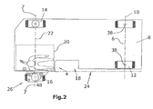
- the chassis carries a machine frame 8, on which a driver's cab 4 on the so-called zero side 24 of the road construction machine according to Fig. 2 located.
- the rear wheels 14, 16 are height adjustable by means of lifting columns 48 in order to adjust the working depth of a milling drum 20 can.
- the milling drum 20 is almost flush with the zero side end face with the zero side 24 of the machine frame, so that on the null side 24 of the road milling machine a close-edge work is possible.
- the wheel 16 is pivoted from an outer end position 26 beyond the zero side plane inwards of the milling drum in a recess 18 of the machine frame 8, so that the outer edge of the wheel 16 can be flush with the zero side 24 or even relative to the zero side 24 an end position on inside can take.
- the rear wheel 16 or both rear wheels 14, 16 may be steerable.
- the Fräswalzenachse 22 runs as best of Fig. 1 seen in substantially the same vertical plane as the axes 7 of the wheel 14 and the wheel 16 in the outer end position 26th
- the engagement circle of the milling drum 20 ends in the vicinity of the rear end of the machine frame 8, so that can be milled close to the edges.
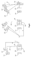
- Fig. 3 shows a steering armature 30 with a connecting part 40 which connects the steering levers 36 of both front wheels 10, 12 hinged together. From this connecting part 40, an arm 50 is initially substantially centrally and preferably orthogonal to the connecting part 40 from.
- the wheel brackets 32 are each connected to pivot columns 34 which are pivotally mounted about a pivot axis 38 in a cross member 56.
- the steering levers 36 are fixedly connected to the wheel brackets 32.
- the arm 50 protruding substantially orthogonally from the connecting part 40 has, on the sides facing the pivoting columns 34, a curved contour 52, 54 which is adapted to the diameter of the pivoting columns 34 in order to be able to set maximum steering angles without collision.
- the arm 50 may be angled or bent to be connected at its free end to a steering cylinder 44 which transmits the force required for steering to the steering armature 30.
- the steering cylinder 44 is in turn hinged to a fixed point 42 directly or indirectly relative to the machine frame 4.
- Fig. 4 shows a side view of the front axle with staggered wheels 10, 12, the pivot columns 34 are mounted in a cross member 56.
- the cross member 56 is hinged to a fixed to the machine frame 8 plate 58 such that the cross member 56 may be pivotable relative to the machine frame 8 about a pendulum axis extending in the direction of travel.
- the cross member 56 is pivotable about a vertical axis parallel to the pivot axes 38 such that the offset "d" can be provided either left or right in the direction of travel, so that each in the steering direction inside wheel 10 or 12 can be arranged in the direction of travel in front of the adjacent wheel.
- Fig. 5 shows an embodiment of the prior art with the relevant for the milling geometric distances.
- the wheelbase "a" of the road milling machine displays In the middle figure, the distance "b" of the center of rotation "D", which is relevant for the milling operation, is shown from the end side of the milling drum 20 facing away from the zero side at maximum steering angle to the left.
- the right picture of the Fig. 5 shows the same situation at maximum steering angle to the right, in which the zero side 24 lies on the inside of the curve.
- the maximum adjustable steering angle of the front wheels 10, 12 is of great importance, but also the distance "c" from the center of rotation D to the zero-side end face of the milling drum 20. It is understood that milled at a smaller distance "c” tighter curve radii can be.
- Fig. 6 now shows an embodiment of the invention, in which the front wheels 10, 12 are arranged offset to one another.
- the wheelbase "a” is maintained, while the left front wheel 10 is set back by an offset "d".
- the offset "d" may for example be in a range between 50 mm to 350 mm, preferably between 100 mm to 250 mm.
- This offset has the first from the middle picture of the Fig. 6 apparent advantage that the steering angle of the right front wheel 12 can be increased, whereby the distance "b" between the center of rotation and the left end of the milling drum 20 can be significantly shortened, so that also improves the maneuverability of the road milling machine inwards relative to the neutral side 24 becomes.
- the maximum steering angle can be increased to 75 °, for example, due to the staggered arrangement of the front wheels 10, 12, whereby the distance "c" of the center of rotation "D" to the zero-side end face of the milling drum 20 considerably, ie by about 20 % across from Fig. 5 , can be reduced.
- Fig. 7 In addition to the offset "d" of the front wheels 10, 12, the application of a steering armature 30, which, as shown in the middle figure of FIG Fig. 7 shows, at least with respect to the left wheel 10 allows a larger steering angle, so that the distance "b" opposite Fig. 4 can be further reduced.
- the steering angle can be further increased, so that the distance "c" by about 65% compared Fig. 5 can be reduced, whereby extremely small curve radii are milled at a steering relative to the zero side to the right.
- the distance "c” reaches a size of less than 150 mm.
- For "b” a value of, for example, about 1700 mm can be achieved.
- FIG. 6 and 7 Another advantage of the embodiments according to Fig. 6 and 7 is that the front wheels 10, 12 can be driven at a maximum steering angle from the null side outwards on a roughly similar radius, so that the wheels 10, 12 drive substantially on the same track.
- Fig. 6 are steering angle for the front wheels 10, 12 shown between 55 ° and 75 ° and in the embodiment of Fig. 7 are steering angles of the front wheels between 59 ° and 79 ° visible.
Landscapes
- Engineering & Computer Science (AREA)
- Mechanical Engineering (AREA)
- Chemical & Material Sciences (AREA)
- Combustion & Propulsion (AREA)
- Transportation (AREA)
- Mining & Mineral Resources (AREA)
- Architecture (AREA)
- Civil Engineering (AREA)
- Structural Engineering (AREA)
- Steering-Linkage Mechanisms And Four-Wheel Steering (AREA)
Applications Claiming Priority (1)
| Application Number | Priority Date | Filing Date | Title |
|---|---|---|---|
| DE102013208539.7A DE102013208539B4 (de) | 2013-05-08 | 2013-05-08 | Vorrichtung zum Bearbeiten von Straßen- oder Bodenoberflächen |
Publications (2)
| Publication Number | Publication Date |
|---|---|
| EP2801664A1 true EP2801664A1 (fr) | 2014-11-12 |
| EP2801664B1 EP2801664B1 (fr) | 2018-11-21 |
Family
ID=50549067
Family Applications (1)
| Application Number | Title | Priority Date | Filing Date |
|---|---|---|---|
| EP14166468.0A Active EP2801664B1 (fr) | 2013-05-08 | 2014-04-29 | Fraiseuse routière destinée à traiter les surfaces routières et de sol |
Country Status (4)
| Country | Link |
|---|---|
| US (2) | US9382676B2 (fr) |
| EP (1) | EP2801664B1 (fr) |
| CN (2) | CN203960720U (fr) |
| DE (1) | DE102013208539B4 (fr) |
Cited By (2)
| Publication number | Priority date | Publication date | Assignee | Title |
|---|---|---|---|---|
| ITUB20150531A1 (it) * | 2015-04-21 | 2016-10-21 | Ormig S P A | Sistema sterzante di una gru semovente. |
| CN113250055A (zh) * | 2020-01-28 | 2021-08-13 | 卡特彼勒路面机械公司 | 具有偏离发动机输出轴的枢转臂的铣床 |
Families Citing this family (6)
| Publication number | Priority date | Publication date | Assignee | Title |
|---|---|---|---|---|
| DE102013208539B4 (de) * | 2013-05-08 | 2023-07-27 | Wirtgen Gmbh | Vorrichtung zum Bearbeiten von Straßen- oder Bodenoberflächen |
| DE202015101552U1 (de) | 2015-03-26 | 2015-05-07 | Stehr Baumaschinen Gmbh | Rotierendes Fräswerkzeug mit einer Vielzahl von auswechselbaren Werkzeugköpfen und Werkzeugkopf für ein solches rotierendes Fräswerkzeug |
| CN104818663B (zh) * | 2015-04-24 | 2017-01-11 | 北京航空航天大学 | 一种铣刨机车身底盘机构 |
| DE102016108306A1 (de) | 2016-05-04 | 2017-11-09 | Jürgen Stehr | Rotierendes Fräswerkzeug mit einer Vielzahl von auswechselbaren Werkzeugköpfen und Werkzeugkopf für ein solches rotierendes Fräswerkzeug |
| DE102020120243B4 (de) * | 2020-07-31 | 2022-02-17 | Wirtgen Gmbh | Baumaschine |
| JP2023068985A (ja) * | 2021-11-04 | 2023-05-18 | ヤマハ発動機株式会社 | 車両 |
Citations (5)
| Publication number | Priority date | Publication date | Assignee | Title |
|---|---|---|---|---|
| US3606827A (en) | 1968-11-07 | 1971-09-21 | Miller Formless Co Inc | Concrete curb laying machine |
| DE4334742A1 (de) | 1993-10-12 | 1995-04-13 | Francke Renate | Deaktivierbare Achslenkung |
| WO1997042377A1 (fr) | 1996-05-02 | 1997-11-13 | Wirtgen Gmbh | Chassis de machine destinee au rabotage de revetements routiers |
| DE29924566U1 (de) * | 1999-03-23 | 2004-01-15 | Bitelli S.P.A. | Arbeitsfahrzeug für Bodenbearbeitung mit einziehbaren und lenkbaren Hinterrädern |
| CN201999061U (zh) * | 2011-01-07 | 2011-10-05 | 三一重工股份有限公司 | 轮式摊铺机和前轮转角测量装置 |
Family Cites Families (22)
| Publication number | Priority date | Publication date | Assignee | Title |
|---|---|---|---|---|
| US3398808A (en) * | 1965-01-04 | 1968-08-27 | Huber Corp J M | Front wheel axle suspension |
| CH584809A5 (fr) | 1973-07-10 | 1977-02-15 | Wirtgen Reinhard | |
| US3895843A (en) | 1973-10-23 | 1975-07-22 | British Jeffrey Diamond Limite | Road planing machine |
| US3990534A (en) * | 1975-10-20 | 1976-11-09 | General Motors Corporation | Power steering system |
| US4270801A (en) | 1979-08-14 | 1981-06-02 | Cmi Corporation | Steering and cutter drum positioning in a paved roadway planing machine |
| US5577808A (en) * | 1995-04-03 | 1996-11-26 | Trencor, Inc. | Quarry miner |
| JPH107009A (ja) * | 1996-06-19 | 1998-01-13 | Kanzaki Kokyukoki Mfg Co Ltd | パワーステアリングシリンダーの取付構造 |
| DE19631042C5 (de) | 1996-08-01 | 2015-08-20 | Wirtgen Gmbh | Straßenbaumaschinen zum Bearbeiten von Fahrbahnen |
| GB9623689D0 (en) * | 1996-11-14 | 1997-01-08 | Tetlaw Contracting Company Lim | Road planing machines |
| IT1292872B1 (it) | 1997-04-22 | 1999-02-11 | New Holland Italia Spa | Gruppo di sterzo per un automezzo da lavoro. |
| IT1308143B1 (it) | 1999-03-23 | 2001-11-29 | Bitelli Spa | Macchina operatrice per la lavorazione di suoli con ruote posterioririentranti e sterzanti. |
| WO2000064800A1 (fr) * | 1999-04-26 | 2000-11-02 | Tcm Corporation | Leve-palette dote d'un systeme de deplacement lateral |
| CA2281162C (fr) | 1999-08-27 | 2005-05-10 | Larry Titford | Methode et appareil pour effectuer des travaux de terrassement |
| US6510917B2 (en) * | 2001-03-28 | 2003-01-28 | Delphi Technologies, Inc. | Rear wheel steering apparatus |
| DE10210763A1 (de) * | 2002-03-12 | 2003-10-02 | Metso Dynapac Gmbh | Straßendeckenfräse |
| WO2008042244A2 (fr) | 2006-09-29 | 2008-04-10 | Volvo Construction Equipment Ab | systÈme de direction et de propulsion pour une FRAISEUSE ROUTIÈRE |
| US7547028B1 (en) * | 2007-01-08 | 2009-06-16 | Trw Automotive U.S. Llc | Tie rod steering linkage |
| US7854293B2 (en) * | 2007-02-20 | 2010-12-21 | Textron Innovations Inc. | Steering operated by linear electric device |
| DE102007033808B4 (de) * | 2007-07-05 | 2025-01-30 | Wirtgen Gmbh | Selbstfahrende Großfräse |
| DE102009059106A1 (de) | 2009-12-18 | 2011-06-22 | Wirtgen GmbH, 53578 | Selbstfahrende Baumaschine und Verfahren zur Steuerung einer selbstfahrenden Baumaschine |
| DE102013208539B4 (de) * | 2013-05-08 | 2023-07-27 | Wirtgen Gmbh | Vorrichtung zum Bearbeiten von Straßen- oder Bodenoberflächen |
| DE102013208484B4 (de) | 2013-05-08 | 2018-04-26 | Wirtgen Gmbh | Vorrichtung zum Bearbeiten von Straßen- oder Bodenoberflächen, sowie Verfahren zum Lenken einer Straßenfräsmaschine |
-
2013
- 2013-05-08 DE DE102013208539.7A patent/DE102013208539B4/de active Active
-
2014
- 2014-04-29 EP EP14166468.0A patent/EP2801664B1/fr active Active
- 2014-05-02 US US14/268,497 patent/US9382676B2/en active Active
- 2014-05-08 CN CN201420232817.7U patent/CN203960720U/zh not_active Withdrawn - After Issue
- 2014-05-08 CN CN201410192550.8A patent/CN104141277B/zh active Active
-
2016
- 2016-06-29 US US15/196,157 patent/US9850628B2/en active Active
Patent Citations (6)
| Publication number | Priority date | Publication date | Assignee | Title |
|---|---|---|---|---|
| US3606827A (en) | 1968-11-07 | 1971-09-21 | Miller Formless Co Inc | Concrete curb laying machine |
| DE4334742A1 (de) | 1993-10-12 | 1995-04-13 | Francke Renate | Deaktivierbare Achslenkung |
| WO1997042377A1 (fr) | 1996-05-02 | 1997-11-13 | Wirtgen Gmbh | Chassis de machine destinee au rabotage de revetements routiers |
| EP0836659A1 (fr) | 1996-05-02 | 1998-04-22 | WIRTGEN GmbH | Chassis de machine destinee au rabotage de revetements routiers |
| DE29924566U1 (de) * | 1999-03-23 | 2004-01-15 | Bitelli S.P.A. | Arbeitsfahrzeug für Bodenbearbeitung mit einziehbaren und lenkbaren Hinterrädern |
| CN201999061U (zh) * | 2011-01-07 | 2011-10-05 | 三一重工股份有限公司 | 轮式摊铺机和前轮转角测量装置 |
Cited By (3)
| Publication number | Priority date | Publication date | Assignee | Title |
|---|---|---|---|---|
| ITUB20150531A1 (it) * | 2015-04-21 | 2016-10-21 | Ormig S P A | Sistema sterzante di una gru semovente. |
| EP3093216A1 (fr) * | 2015-04-21 | 2016-11-16 | ORMIG S.p.A. | Un systeme de direction pour une grue automotrice |
| CN113250055A (zh) * | 2020-01-28 | 2021-08-13 | 卡特彼勒路面机械公司 | 具有偏离发动机输出轴的枢转臂的铣床 |
Also Published As
| Publication number | Publication date |
|---|---|
| CN104141277B (zh) | 2016-08-31 |
| US9382676B2 (en) | 2016-07-05 |
| US9850628B2 (en) | 2017-12-26 |
| US20140333119A1 (en) | 2014-11-13 |
| US20160369459A1 (en) | 2016-12-22 |
| CN104141277A (zh) | 2014-11-12 |
| EP2801664B1 (fr) | 2018-11-21 |
| DE102013208539B4 (de) | 2023-07-27 |
| CN203960720U (zh) | 2014-11-26 |
| DE102013208539A1 (de) | 2014-11-13 |
Similar Documents
| Publication | Publication Date | Title |
|---|---|---|
| DE102013208484B4 (de) | Vorrichtung zum Bearbeiten von Straßen- oder Bodenoberflächen, sowie Verfahren zum Lenken einer Straßenfräsmaschine | |
| EP2801664B1 (fr) | Fraiseuse routière destinée à traiter les surfaces routières et de sol | |
| EP2823102B1 (fr) | Fraiseuse routière automotrice destinée à usiner des surfaces routières, et procédé d'usinage de surfaces routières | |
| EP2011921B1 (fr) | Grande fraiseuse de route automobile | |
| EP2700747B1 (fr) | Machine à fraiser la chaussée destinée au traitement de revêtements routiers et procédé de basculement d'un train de roulement d'une machine à fraiser la chaussée | |
| DE2415363A1 (de) | Halterungsvorrichtung zum befestigen eines arbeitsgeraets an einem fahrzeug | |
| DE2544525A1 (de) | Fahrbarer kran | |
| EP0065118B1 (fr) | Excavatrice | |
| DE10210556B4 (de) | Fahrzeugachse | |
| DE2928577A1 (de) | Ackerschlepper mit lenkbaren, ueber lenkzapfen angeordneten raedern | |
| EP0638471B1 (fr) | Machine de construction | |
| DE102016009646A1 (de) | Bodenfräse und Verfahren zum Betrieb einer Bodenfräse | |
| EP0557763B1 (fr) | Machine de fraisage | |
| DE2905528A1 (de) | Achsschenkelgelenktes kraftfahrzeug | |
| DE9417893U1 (de) | Mähmaschine | |
| DE19935160A1 (de) | Vorrichtung zur Erhöhung der Lenkfähigkeit getriebener Achsen | |
| EP4108556B1 (fr) | Véhicule et utilisation correspondante | |
| DE2328410B2 (de) | Arbeitszug, insbesondere zur Bodenbearbeitung | |
| DE1253597B (de) | Lenkeinrichtung fuer vierraedrige Portalfahrzeuge und aehnliche fahrbare Geraete | |
| DE3136158A1 (de) | "strassenwalze" | |
| EP3556946B1 (fr) | Engin de travail à stabilité améliorée | |
| DE102008044794B3 (de) | Radfahrzeug, insbesondere Forstmaschine | |
| EP4686787A1 (fr) | Fraise pour parois moulées avec un outil de coupe réglable | |
| DE10219214A1 (de) | Baufahrzeug | |
| DE3230659A1 (de) | Selbstfahrende arbeitsmaschine |
Legal Events
| Date | Code | Title | Description |
|---|---|---|---|
| PUAI | Public reference made under article 153(3) epc to a published international application that has entered the european phase |
Free format text: ORIGINAL CODE: 0009012 |
|
| 17P | Request for examination filed |
Effective date: 20140429 |
|
| AK | Designated contracting states |
Kind code of ref document: A1 Designated state(s): AL AT BE BG CH CY CZ DE DK EE ES FI FR GB GR HR HU IE IS IT LI LT LU LV MC MK MT NL NO PL PT RO RS SE SI SK SM TR |
|
| AX | Request for extension of the european patent |
Extension state: BA ME |
|
| TPAC | Observations filed by third parties |
Free format text: ORIGINAL CODE: EPIDOSNTIPA |
|
| R17P | Request for examination filed (corrected) |
Effective date: 20150506 |
|
| RBV | Designated contracting states (corrected) |
Designated state(s): AL AT BE BG CH CY CZ DE DK EE ES FI FR GB GR HR HU IE IS IT LI LT LU LV MC MK MT NL NO PL PT RO RS SE SI SK SM TR |
|
| 17Q | First examination report despatched |
Effective date: 20160407 |
|
| STAA | Information on the status of an ep patent application or granted ep patent |
Free format text: STATUS: EXAMINATION IS IN PROGRESS |
|
| GRAP | Despatch of communication of intention to grant a patent |
Free format text: ORIGINAL CODE: EPIDOSNIGR1 |
|
| STAA | Information on the status of an ep patent application or granted ep patent |
Free format text: STATUS: GRANT OF PATENT IS INTENDED |
|
| INTG | Intention to grant announced |
Effective date: 20180615 |
|
| GRAS | Grant fee paid |
Free format text: ORIGINAL CODE: EPIDOSNIGR3 |
|
| GRAA | (expected) grant |
Free format text: ORIGINAL CODE: 0009210 |
|
| STAA | Information on the status of an ep patent application or granted ep patent |
Free format text: STATUS: THE PATENT HAS BEEN GRANTED |
|
| AK | Designated contracting states |
Kind code of ref document: B1 Designated state(s): AL AT BE BG CH CY CZ DE DK EE ES FI FR GB GR HR HU IE IS IT LI LT LU LV MC MK MT NL NO PL PT RO RS SE SI SK SM TR |
|
| REG | Reference to a national code |
Ref country code: CH Ref legal event code: EP |
|
| REG | Reference to a national code |
Ref country code: IE Ref legal event code: FG4D Free format text: LANGUAGE OF EP DOCUMENT: GERMAN |
|
| REG | Reference to a national code |
Ref country code: DE Ref legal event code: R096 Ref document number: 502014010119 Country of ref document: DE |
|
| REG | Reference to a national code |
Ref country code: AT Ref legal event code: REF Ref document number: 1067673 Country of ref document: AT Kind code of ref document: T Effective date: 20181215 |
|
| REG | Reference to a national code |
Ref country code: SE Ref legal event code: TRGR |
|
| REG | Reference to a national code |
Ref country code: NL Ref legal event code: MP Effective date: 20181121 |
|
| PG25 | Lapsed in a contracting state [announced via postgrant information from national office to epo] |
Ref country code: LV Free format text: LAPSE BECAUSE OF FAILURE TO SUBMIT A TRANSLATION OF THE DESCRIPTION OR TO PAY THE FEE WITHIN THE PRESCRIBED TIME-LIMIT Effective date: 20181121 Ref country code: HR Free format text: LAPSE BECAUSE OF FAILURE TO SUBMIT A TRANSLATION OF THE DESCRIPTION OR TO PAY THE FEE WITHIN THE PRESCRIBED TIME-LIMIT Effective date: 20181121 Ref country code: NO Free format text: LAPSE BECAUSE OF FAILURE TO SUBMIT A TRANSLATION OF THE DESCRIPTION OR TO PAY THE FEE WITHIN THE PRESCRIBED TIME-LIMIT Effective date: 20190221 Ref country code: LT Free format text: LAPSE BECAUSE OF FAILURE TO SUBMIT A TRANSLATION OF THE DESCRIPTION OR TO PAY THE FEE WITHIN THE PRESCRIBED TIME-LIMIT Effective date: 20181121 Ref country code: BG Free format text: LAPSE BECAUSE OF FAILURE TO SUBMIT A TRANSLATION OF THE DESCRIPTION OR TO PAY THE FEE WITHIN THE PRESCRIBED TIME-LIMIT Effective date: 20190221 Ref country code: ES Free format text: LAPSE BECAUSE OF FAILURE TO SUBMIT A TRANSLATION OF THE DESCRIPTION OR TO PAY THE FEE WITHIN THE PRESCRIBED TIME-LIMIT Effective date: 20181121 Ref country code: IS Free format text: LAPSE BECAUSE OF FAILURE TO SUBMIT A TRANSLATION OF THE DESCRIPTION OR TO PAY THE FEE WITHIN THE PRESCRIBED TIME-LIMIT Effective date: 20190321 Ref country code: FI Free format text: LAPSE BECAUSE OF FAILURE TO SUBMIT A TRANSLATION OF THE DESCRIPTION OR TO PAY THE FEE WITHIN THE PRESCRIBED TIME-LIMIT Effective date: 20181121 |
|
| PG25 | Lapsed in a contracting state [announced via postgrant information from national office to epo] |
Ref country code: GR Free format text: LAPSE BECAUSE OF FAILURE TO SUBMIT A TRANSLATION OF THE DESCRIPTION OR TO PAY THE FEE WITHIN THE PRESCRIBED TIME-LIMIT Effective date: 20190222 Ref country code: RS Free format text: LAPSE BECAUSE OF FAILURE TO SUBMIT A TRANSLATION OF THE DESCRIPTION OR TO PAY THE FEE WITHIN THE PRESCRIBED TIME-LIMIT Effective date: 20181121 Ref country code: AL Free format text: LAPSE BECAUSE OF FAILURE TO SUBMIT A TRANSLATION OF THE DESCRIPTION OR TO PAY THE FEE WITHIN THE PRESCRIBED TIME-LIMIT Effective date: 20181121 Ref country code: PT Free format text: LAPSE BECAUSE OF FAILURE TO SUBMIT A TRANSLATION OF THE DESCRIPTION OR TO PAY THE FEE WITHIN THE PRESCRIBED TIME-LIMIT Effective date: 20190321 Ref country code: NL Free format text: LAPSE BECAUSE OF FAILURE TO SUBMIT A TRANSLATION OF THE DESCRIPTION OR TO PAY THE FEE WITHIN THE PRESCRIBED TIME-LIMIT Effective date: 20181121 |
|
| PG25 | Lapsed in a contracting state [announced via postgrant information from national office to epo] |
Ref country code: DK Free format text: LAPSE BECAUSE OF FAILURE TO SUBMIT A TRANSLATION OF THE DESCRIPTION OR TO PAY THE FEE WITHIN THE PRESCRIBED TIME-LIMIT Effective date: 20181121 Ref country code: PL Free format text: LAPSE BECAUSE OF FAILURE TO SUBMIT A TRANSLATION OF THE DESCRIPTION OR TO PAY THE FEE WITHIN THE PRESCRIBED TIME-LIMIT Effective date: 20181121 Ref country code: CZ Free format text: LAPSE BECAUSE OF FAILURE TO SUBMIT A TRANSLATION OF THE DESCRIPTION OR TO PAY THE FEE WITHIN THE PRESCRIBED TIME-LIMIT Effective date: 20181121 |
|
| REG | Reference to a national code |
Ref country code: DE Ref legal event code: R097 Ref document number: 502014010119 Country of ref document: DE |
|
| PG25 | Lapsed in a contracting state [announced via postgrant information from national office to epo] |
Ref country code: RO Free format text: LAPSE BECAUSE OF FAILURE TO SUBMIT A TRANSLATION OF THE DESCRIPTION OR TO PAY THE FEE WITHIN THE PRESCRIBED TIME-LIMIT Effective date: 20181121 Ref country code: EE Free format text: LAPSE BECAUSE OF FAILURE TO SUBMIT A TRANSLATION OF THE DESCRIPTION OR TO PAY THE FEE WITHIN THE PRESCRIBED TIME-LIMIT Effective date: 20181121 Ref country code: SM Free format text: LAPSE BECAUSE OF FAILURE TO SUBMIT A TRANSLATION OF THE DESCRIPTION OR TO PAY THE FEE WITHIN THE PRESCRIBED TIME-LIMIT Effective date: 20181121 Ref country code: SK Free format text: LAPSE BECAUSE OF FAILURE TO SUBMIT A TRANSLATION OF THE DESCRIPTION OR TO PAY THE FEE WITHIN THE PRESCRIBED TIME-LIMIT Effective date: 20181121 |
|
| PLBE | No opposition filed within time limit |
Free format text: ORIGINAL CODE: 0009261 |
|
| STAA | Information on the status of an ep patent application or granted ep patent |
Free format text: STATUS: NO OPPOSITION FILED WITHIN TIME LIMIT |
|
| 26N | No opposition filed |
Effective date: 20190822 |
|
| PG25 | Lapsed in a contracting state [announced via postgrant information from national office to epo] |
Ref country code: SI Free format text: LAPSE BECAUSE OF FAILURE TO SUBMIT A TRANSLATION OF THE DESCRIPTION OR TO PAY THE FEE WITHIN THE PRESCRIBED TIME-LIMIT Effective date: 20181121 |
|
| REG | Reference to a national code |
Ref country code: CH Ref legal event code: PL |
|
| REG | Reference to a national code |
Ref country code: BE Ref legal event code: MM Effective date: 20190430 |
|
| PG25 | Lapsed in a contracting state [announced via postgrant information from national office to epo] |
Ref country code: LU Free format text: LAPSE BECAUSE OF NON-PAYMENT OF DUE FEES Effective date: 20190429 Ref country code: MC Free format text: LAPSE BECAUSE OF FAILURE TO SUBMIT A TRANSLATION OF THE DESCRIPTION OR TO PAY THE FEE WITHIN THE PRESCRIBED TIME-LIMIT Effective date: 20181121 |
|
| PG25 | Lapsed in a contracting state [announced via postgrant information from national office to epo] |
Ref country code: LI Free format text: LAPSE BECAUSE OF NON-PAYMENT OF DUE FEES Effective date: 20190430 Ref country code: CH Free format text: LAPSE BECAUSE OF NON-PAYMENT OF DUE FEES Effective date: 20190430 |
|
| PG25 | Lapsed in a contracting state [announced via postgrant information from national office to epo] |
Ref country code: BE Free format text: LAPSE BECAUSE OF NON-PAYMENT OF DUE FEES Effective date: 20190430 |
|
| PG25 | Lapsed in a contracting state [announced via postgrant information from national office to epo] |
Ref country code: TR Free format text: LAPSE BECAUSE OF FAILURE TO SUBMIT A TRANSLATION OF THE DESCRIPTION OR TO PAY THE FEE WITHIN THE PRESCRIBED TIME-LIMIT Effective date: 20181121 |
|
| PG25 | Lapsed in a contracting state [announced via postgrant information from national office to epo] |
Ref country code: IE Free format text: LAPSE BECAUSE OF NON-PAYMENT OF DUE FEES Effective date: 20190429 |
|
| REG | Reference to a national code |
Ref country code: AT Ref legal event code: MM01 Ref document number: 1067673 Country of ref document: AT Kind code of ref document: T Effective date: 20190429 |
|
| PG25 | Lapsed in a contracting state [announced via postgrant information from national office to epo] |
Ref country code: AT Free format text: LAPSE BECAUSE OF NON-PAYMENT OF DUE FEES Effective date: 20190429 |
|
| PG25 | Lapsed in a contracting state [announced via postgrant information from national office to epo] |
Ref country code: CY Free format text: LAPSE BECAUSE OF FAILURE TO SUBMIT A TRANSLATION OF THE DESCRIPTION OR TO PAY THE FEE WITHIN THE PRESCRIBED TIME-LIMIT Effective date: 20181121 |
|
| PG25 | Lapsed in a contracting state [announced via postgrant information from national office to epo] |
Ref country code: HU Free format text: LAPSE BECAUSE OF FAILURE TO SUBMIT A TRANSLATION OF THE DESCRIPTION OR TO PAY THE FEE WITHIN THE PRESCRIBED TIME-LIMIT; INVALID AB INITIO Effective date: 20140429 Ref country code: MT Free format text: LAPSE BECAUSE OF FAILURE TO SUBMIT A TRANSLATION OF THE DESCRIPTION OR TO PAY THE FEE WITHIN THE PRESCRIBED TIME-LIMIT Effective date: 20181121 |
|
| PG25 | Lapsed in a contracting state [announced via postgrant information from national office to epo] |
Ref country code: MK Free format text: LAPSE BECAUSE OF FAILURE TO SUBMIT A TRANSLATION OF THE DESCRIPTION OR TO PAY THE FEE WITHIN THE PRESCRIBED TIME-LIMIT Effective date: 20181121 |
|
| P01 | Opt-out of the competence of the unified patent court (upc) registered |
Effective date: 20230525 |
|
| PGFP | Annual fee paid to national office [announced via postgrant information from national office to epo] |
Ref country code: DE Payment date: 20250417 Year of fee payment: 12 |
|
| PGFP | Annual fee paid to national office [announced via postgrant information from national office to epo] |
Ref country code: IT Payment date: 20250430 Year of fee payment: 12 |
|
| PGFP | Annual fee paid to national office [announced via postgrant information from national office to epo] |
Ref country code: FR Payment date: 20250425 Year of fee payment: 12 |
|
| PGFP | Annual fee paid to national office [announced via postgrant information from national office to epo] |
Ref country code: SE Payment date: 20250423 Year of fee payment: 12 |
|
| PGFP | Annual fee paid to national office [announced via postgrant information from national office to epo] |
Ref country code: GB Payment date: 20260324 Year of fee payment: 13 |