EP2801701B1 - Turbinenschaufel - Google Patents
Turbinenschaufel Download PDFInfo
- Publication number
- EP2801701B1 EP2801701B1 EP12856805.2A EP12856805A EP2801701B1 EP 2801701 B1 EP2801701 B1 EP 2801701B1 EP 12856805 A EP12856805 A EP 12856805A EP 2801701 B1 EP2801701 B1 EP 2801701B1
- Authority
- EP
- European Patent Office
- Prior art keywords
- wall surface
- cooling air
- blade body
- convex portion
- air hole
- Prior art date
- Legal status (The legal status is an assumption and is not a legal conclusion. Google has not performed a legal analysis and makes no representation as to the accuracy of the status listed.)
- Active
Links
Images

Classifications
-
- F—MECHANICAL ENGINEERING; LIGHTING; HEATING; WEAPONS; BLASTING
- F01—MACHINES OR ENGINES IN GENERAL; ENGINE PLANTS IN GENERAL; STEAM ENGINES
- F01D—NON-POSITIVE DISPLACEMENT MACHINES OR ENGINES, e.g. STEAM TURBINES
- F01D5/00—Blades; Blade-carrying members; Heating, heat-insulating, cooling or antivibration means on the blades or the members
- F01D5/12—Blades
- F01D5/14—Form or construction
- F01D5/18—Hollow blades, i.e. blades with cooling or heating channels or cavities; Heating, heat-insulating or cooling means on blades
-
- F—MECHANICAL ENGINEERING; LIGHTING; HEATING; WEAPONS; BLASTING
- F01—MACHINES OR ENGINES IN GENERAL; ENGINE PLANTS IN GENERAL; STEAM ENGINES
- F01D—NON-POSITIVE DISPLACEMENT MACHINES OR ENGINES, e.g. STEAM TURBINES
- F01D5/00—Blades; Blade-carrying members; Heating, heat-insulating, cooling or antivibration means on the blades or the members
- F01D5/12—Blades
- F01D5/14—Form or construction
- F01D5/18—Hollow blades, i.e. blades with cooling or heating channels or cavities; Heating, heat-insulating or cooling means on blades
- F01D5/186—Film cooling
-
- F—MECHANICAL ENGINEERING; LIGHTING; HEATING; WEAPONS; BLASTING
- F01—MACHINES OR ENGINES IN GENERAL; ENGINE PLANTS IN GENERAL; STEAM ENGINES
- F01D—NON-POSITIVE DISPLACEMENT MACHINES OR ENGINES, e.g. STEAM TURBINES
- F01D9/00—Stators
- F01D9/06—Fluid supply conduits to nozzles or the like
- F01D9/065—Fluid supply or removal conduits traversing the working fluid flow, e.g. for lubrication-, cooling-, or sealing fluids
-
- F—MECHANICAL ENGINEERING; LIGHTING; HEATING; WEAPONS; BLASTING
- F05—INDEXING SCHEMES RELATING TO ENGINES OR PUMPS IN VARIOUS SUBCLASSES OF CLASSES F01-F04
- F05D—INDEXING SCHEME FOR ASPECTS RELATING TO NON-POSITIVE-DISPLACEMENT MACHINES OR ENGINES, GAS-TURBINES OR JET-PROPULSION PLANTS
- F05D2240/00—Components
- F05D2240/80—Platforms for stationary or moving blades
- F05D2240/81—Cooled platforms
-
- F—MECHANICAL ENGINEERING; LIGHTING; HEATING; WEAPONS; BLASTING
- F05—INDEXING SCHEMES RELATING TO ENGINES OR PUMPS IN VARIOUS SUBCLASSES OF CLASSES F01-F04
- F05D—INDEXING SCHEME FOR ASPECTS RELATING TO NON-POSITIVE-DISPLACEMENT MACHINES OR ENGINES, GAS-TURBINES OR JET-PROPULSION PLANTS
- F05D2250/00—Geometry
- F05D2250/20—Three-dimensional
- F05D2250/21—Three-dimensional pyramidal
-
- F—MECHANICAL ENGINEERING; LIGHTING; HEATING; WEAPONS; BLASTING
- F05—INDEXING SCHEMES RELATING TO ENGINES OR PUMPS IN VARIOUS SUBCLASSES OF CLASSES F01-F04
- F05D—INDEXING SCHEME FOR ASPECTS RELATING TO NON-POSITIVE-DISPLACEMENT MACHINES OR ENGINES, GAS-TURBINES OR JET-PROPULSION PLANTS
- F05D2250/00—Geometry
- F05D2250/20—Three-dimensional
- F05D2250/23—Three-dimensional prismatic
-
- F—MECHANICAL ENGINEERING; LIGHTING; HEATING; WEAPONS; BLASTING
- F05—INDEXING SCHEMES RELATING TO ENGINES OR PUMPS IN VARIOUS SUBCLASSES OF CLASSES F01-F04
- F05D—INDEXING SCHEME FOR ASPECTS RELATING TO NON-POSITIVE-DISPLACEMENT MACHINES OR ENGINES, GAS-TURBINES OR JET-PROPULSION PLANTS
- F05D2260/00—Function
- F05D2260/20—Heat transfer, e.g. cooling
- F05D2260/202—Heat transfer, e.g. cooling by film cooling
-
- F—MECHANICAL ENGINEERING; LIGHTING; HEATING; WEAPONS; BLASTING
- F05—INDEXING SCHEMES RELATING TO ENGINES OR PUMPS IN VARIOUS SUBCLASSES OF CLASSES F01-F04
- F05D—INDEXING SCHEME FOR ASPECTS RELATING TO NON-POSITIVE-DISPLACEMENT MACHINES OR ENGINES, GAS-TURBINES OR JET-PROPULSION PLANTS
- F05D2260/00—Function
- F05D2260/20—Heat transfer, e.g. cooling
- F05D2260/221—Improvement of heat transfer
- F05D2260/2212—Improvement of heat transfer by creating turbulence
-
- F—MECHANICAL ENGINEERING; LIGHTING; HEATING; WEAPONS; BLASTING
- F23—COMBUSTION APPARATUS; COMBUSTION PROCESSES
- F23R—GENERATING COMBUSTION PRODUCTS OF HIGH PRESSURE OR HIGH VELOCITY, e.g. GAS-TURBINE COMBUSTION CHAMBERS
- F23R2900/00—Special features of, or arrangements for continuous combustion chambers; Combustion processes therefor
- F23R2900/03042—Film cooled combustion chamber walls or domes
-
- F—MECHANICAL ENGINEERING; LIGHTING; HEATING; WEAPONS; BLASTING
- F23—COMBUSTION APPARATUS; COMBUSTION PROCESSES
- F23R—GENERATING COMBUSTION PRODUCTS OF HIGH PRESSURE OR HIGH VELOCITY, e.g. GAS-TURBINE COMBUSTION CHAMBERS
- F23R2900/00—Special features of, or arrangements for continuous combustion chambers; Combustion processes therefor
- F23R2900/03043—Convection cooled combustion chamber walls with means for guiding the cooling air flow
-
- F—MECHANICAL ENGINEERING; LIGHTING; HEATING; WEAPONS; BLASTING
- F23—COMBUSTION APPARATUS; COMBUSTION PROCESSES
- F23R—GENERATING COMBUSTION PRODUCTS OF HIGH PRESSURE OR HIGH VELOCITY, e.g. GAS-TURBINE COMBUSTION CHAMBERS
- F23R2900/00—Special features of, or arrangements for continuous combustion chambers; Combustion processes therefor
- F23R2900/03045—Convection cooled combustion chamber walls provided with turbolators or means for creating turbulences to increase cooling
Definitions
- Patent Documents 1 to 4 discloses a turbine blade that partitions cooling air that is jetted out from a cooling hole with a projection.
- the present invention was achieved in view of the aforementioned circumstances, and has as its object to further raise the cooling effectiveness of turbine blades that a gas turbine engine and the like is provided with.
- the convex portion is provided in the inner portion of the cooling air hole, the cooling air that has ridden over the convex portion is not affected by other flows such as a main flow gas. For this reason, it is possible to cause most of the cooling air that is jetted out from the cooling air hole to contribute to film cooling, without a portion of the cooling air being blown away by the main flow gas. Moreover, since the cooling air spreads out while flowing due to riding over the convex portion, it becomes possible to jet out the cooling air in a wider range.
- the present invention it is possible to jet out the cooling air in a wide range without reducing the cooling air that contributes to the cooling of the outer wall surface of the blade body, and so it is possible to raise the cooling effectiveness of the turbine blade.
- FIG. 1 is a perspective view that shows the outline configuration of the turbine blade 1 of the present embodiment.
- the turbine blade 1 of the present embodiment is a turbine stator blade, and is provided with a blade body 2, band portions 3 that sandwich the blade body 2, and a film cooling portion 4.
- the blade body 2 is arranged on the downstream side of a combustor that is not illustrated, and is arranged in the flow path of a combustion gas G (refer to FIG. 2A ) that is generated by the combustor.
- This blade body 2 is made to have a blade shape having a leading edge 2a, a trailing edge 2b, a positive pressure surface 2c, and a negative pressure surface 2b.
- the blade body 2 is made to be hollow, to have an interior space for guiding cooling air to the inside.
- a cooling air flow path not illustrated is connected to the interior space of the blade body 2 whereby, for example, air that is extracted from a compressor that is installed on the upstream side of the combustor is introduced as the cooling air.
- the band portions 3 are provided sandwiching the blade body 2 from the height direction of the blade body 2, and function as a portion of the flow path wall of the combustion gas G. These band portions 3 are integrated with the tip side and hub side of the blade body 2.
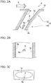
- FIG. 2A is a vertical cross-sectional view of an outline drawing of the film cooling portion 4.
- FIG. 2B is a plan view including a convex portion 6 described below of an outline drawing of the film cooling portion 4.
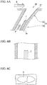
- FIG. 2C is a front elevation seen from the inner wall surface 2e side of the blade body 2 of an outline drawing of the film cooling portion 4. As shown in these drawings, the film cooling portion 4 is provided with a cooling air hole 5 and a convex portion 6.
- the cooling air hole 5 is a through-hole that penetrates from the inner wall surface 2e to the outer wall surface 2f of the blade body 2, and is constituted from a straight pipe portion 5a on the inner wall surface 2e side, and a diameter expansion portion 5b at the outer wall surface 2f side.
- the straight pipe portion 5a is a section that extends in a linear shape, and the cross section shown in FIG. 2A is made to have a long hole shape. Also, the straight pipe portion 5a is sloped so that the end portion of the outer wall surface 2f side is arranged further to the downstream side of the main flow gas G that flows along the outer wall surface 2f of the blade body 2 than the end portion on the inner wall surface 2e side.
- the diameter expansion portion 5b is a section whose flow path cross section increases heading toward the outer wall surface 2f. Note that the diameter expansion portion 5b is made to be a shape in which the side wall surface 5c shown in FIG. 2A, FIG. 2B, and FIG. 2C broadens in the height direction of the blade body 2 heading from the inner wall surface 2e side to the outer wall surface 2f side.
- This kind of cooling air hole 5 guides cooling air Y that is supplied from the interior space of the blade body 2 to the outer wall surface 2f, and after dispersing and spreading out the cooling air Y in the height direction of the blade body 2 in the diameter expansion portion 5b, jets it out it along the outer wall surface 2f.
- the convex portion 6 is arranged in the inner portion of the cooling air hole 5, and is provided projecting from the inner wall surface of the cooling air hole 5. As shown in FIG. 2A, FIG. 2B, and FIG. 2C , the convex portion 6 is made to have a triangular pyramid shape in which a surface of the convex portion 6 on the side of the inner wall surface 2e of the blade body 2 is made to be a triangular collision surface 6a. Also, the convex portion 6 is provided at a region positioned on the downstream side of the flow direction of the combustion gas G (main flow gas), in the inner wall surface of the cooling air hole 5. Moreover, the convex portion 6 is provided at a connection region of the straight pipe portion 5a and the diameter expansion portion 5b.
- a plurality of the film cooling portions 4 that are constituted as described above are provided in the turbine blade 1 of the present embodiment.
- the cooling air Y that is jetted out from this kind of film cooling portion 4 flows along the outer wall surface 2f of the blade body 2, and thereby the outer wall surface 2f of the blade body 2 is film cooled.
- the cooling air flows into the cooling air hole 5 of the film cooling portion 4 from the inner part of the blade body 2.
- the cooling air Y that has flowed into the cooling air hole 5 is guided in a straight manner by the straight pipe portion 5a in which the flow path surface area does not change, and in the diameter expansion portion 5b in which the flow path surface area widens in a continuous way, flows while spreading in the height direction of the blade body 2.
- the cooling air hole 5 that the turbine blade 1 of the present embodiment is provided with, compared with a cooling air hole that consists only of a straight pipe portion, it is possible to jet out the cooling air Y in a wider range in the height direction of the blade body 2, and so it is possible to cool the outer wall surface 2f of the blade body 2 in a wider range.
- the convex portion 6 is provided in the inner portion of the cooling air hole 5. For this reason, the cooling air Y that has ridden over the convex portion 6 is not affected by the flow of the combustion gas G. For this reason, it is possible to cause most of the cooling air Y that is jetted out from the cooling air hole 5 to contribute to film cooling, without a portion of the cooling air Y being blown away by the combustion gas G. Moreover, since the cooling air Y spreads out while flowing due to riding over the convex portion 6, it becomes possible to jet out the cooling air Y in a wider range.
- the turbine blade 1 of the present embodiment it is possible to jet out the cooling air Y in a wide range without reducing the cooling air Y that contributes to the cooling of the outer wall surface 2f of the blade body 2, and so it is possible to raise the cooling effectiveness of the turbine blade 1.
- the convex portion 6 in the turbine blade 1 of the present embodiment is arranged in the inner wall surface of the cooling air hole 5, on the downstream side of the flow direction of the combustion gas G that flows along the outer wall surface 2f of the blade body 2. Thereby, it becomes possible to broadly jet out the cooling air Y in the height direction of the blade body 2.
- the convex portion 6 is provided at the connection region of the straight pipe portion 5a and the diameter expansion portion 5b. Since the diameter expansion portion 5b is spatially wider than the straight pipe portion 5a, due to the provision of the convex portion 6 in the connection region of the straight pipe portion 5a and the diameter expansion portion 5b, it is possible to ensure a space for the cooling air Y, which attempts to spread out by riding over the convex portion 6, to spread out. Accordingly, it is possible to jet out the cooling air Y in a wider range without the spreading out of the cooling air Y being impeded.
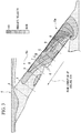
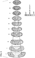
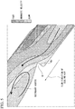
- FIG. 3 to FIG. 5 are drawings that schematically show the result of simulating flows in the film cooling portion 4 of the turbine blade 1 of the present embodiment.
- FIG. 3 shows the distribution of the absolute velocities of the cooling air Y in the film cooling portion 4
- FIG. 4 shows the absolute velocities and local flow directions of the cooling air Y at cross-section A to cross-section J in FIG. 3
- FIG. 5 shows the absolute velocities and local flow directions in the vicinity of the convex portion 6.
- the cooling air Y flows from the straight pipe portion 5a side toward the diameter expansion portion 5b.
- the local flow directions of the cooling air Y in the inner portion of the cooling air hole 5 are indicated with bold arrows.
- FIG. 6A is a vertical cross-sectional view of an outline drawing of the film cooling portion 4A that the turbine blade of the present embodiment is provided with.
- FIG. 6B is a plan view including a convex portion 7 described below of an outline drawing of the film cooling portion 4A that the turbine blade of the present embodiment is provided with.
- FIG. 6C is a front elevation seen from the inner wall surface 2e side of the blade body 2 of an outline drawing of the film cooling portion 4A that the turbine blade of the present embodiment is provided with.
- the film cooling portion 4A is provided with a convex portion 7 that is long in the direction that joins the inner wall surface 2e and the outer wall surface 2f of the blade body 2, instead of the convex portion 6 of the above embodiment.
- the convex portion 7 is arranged in the inner portion of the cooling air hole 5, and is provided projecting from the inner wall surface of the cooling air hole 5. Also, as shown in FIG. 6A, FIG. 6B, and FIG. 6C , the convex portion 7 is made to have a triangular column shape in which a surface of the convex portion 7 on the side of the inner wall surface 2e of the blade body 2 is made to be a triangle shape. Also, the convex portion 7 is provided continuously from the end portion on the inner wall surface 2e of the blade body 2 side of the straight pipe portion 5a to the end portion on the outer wall surface 2f of the blade body 2 side of the straight pipe portion 5a.
- the cooling air Y that has ridden over the convex portion 7 is not affected by the flow of the combustion gas G. For this reason, it is possible to cause most of the cooling air Y that is jetted out from the cooling air hole 5 to contribute to film cooling, without a portion of the cooling air Y being blown away by the combustion gas G. Moreover, since the cooling air Y spreads out while flowing due to riding over the convex portion 7, it becomes possible to jet out the cooling air Y in a wider range.
- the arrangement position and number of the film cooling portion 4 in the blade body 2 of the aforementioned embodiments are just one example, and are suitably changeable in accordance with the cooling performance that is required in the turbine blade.
- the convex portion 6 in the aforementioned embodiment may be installed in the inner portion of the straight pipe portion 5a.
- a turbine blade that a gas turbine engine or the like is provided with, it is possible to jet out cooling air in a wide range without reducing the cooling air that contributes to the cooling of the outer wall surface of a hollow blade body, and it is possible to raise the cooling effectiveness of the turbine blade.
Landscapes
- Engineering & Computer Science (AREA)
- Mechanical Engineering (AREA)
- General Engineering & Computer Science (AREA)
- Physics & Mathematics (AREA)
- Fluid Mechanics (AREA)
- Turbine Rotor Nozzle Sealing (AREA)
Claims (3)
- Turbinenschaufel (1), welche mit einem Kühlungs-Luftloch (5) versehen ist, welches eine innere Wandoberfläche (2e) bis zu einer äußeren Wandoberfläche (2f) eines Schaufelkörpers (2) durchdringt, welcher gestaltet ist, um hohl zu sein, wobei das Kühlungs-Luftloch (5) einen geraden Röhrenabschnitt (5a) aufweist, welcher an der inneren Wandoberflächenseite (2e) des Schaufelkörpers (2) bereitgestellt ist und einen Durchmesser-Expansionsabschnitt (5b), welcher an der äußeren Wandoberflächenseite (2f) des Schaufelkörpers (2) bereitgestellt ist und wobei die Turbinenschaufel (1) Folgendes umfasst:einen konvexen Abschnitt (6), welcher in einem inneren Abschnitt des Kühlungs-Luftlochs (5) angeordnet ist und von einer inneren Wandoberfläche des Kühlungs-Luftlochs (5) nach außen vorspringend bereitgestellt ist, wobeider konvexe Abschnitt (6) an der inneren Wandoberfläche des Kühlungs-Luftlochs (5) bereitgestellt ist, welches an der nachgelagerten Seite einer Strömungsrichtung eines Hauptströmungsgases (G) positioniert ist, welches entlang der äußeren Wandoberfläche (2f) des Schaufelkörpers (2) fließt,dadurch gekennzeichnet, dassder konvexe Abschnitt (6) so gestaltet ist, dass er eine dreieckige Pyramidenform aufweist, wobei eine Oberfläche des konvexen Abschnittes (6) an der Seite der inneren Wandoberfläche (2e) des Schaufelkörpers (2) als eine dreieckige Kollisionsoberfläche (6a) gestaltet ist, undder konvexe Abschnitt (6) an dem geraden Röhrenabschnitt (5a) bereitgestellt ist.
- Turbinenschaufel (1), welche mit einem Kühlungs-Luftloch (5) versehen ist, welches eine innere Wandoberfläche (2e) bis zu einer äußeren Wandoberfläche (2f) eines Schaufelkörpers (2) durchdringt, welcher gestaltet ist, um hohl zu sein, wobei das Kühlungs-Luftloch (5) einen geraden Röhrenabschnitt (5a) aufweist, welcher an der inneren Wandoberflächenseite (2e) des Schaufelkörpers (2) bereitgestellt ist und einen Durchmesser-Expansionsabschnitt (5b), welcher an der äußeren Wandoberflächenseite (2f) des Schaufelkörpers (2) bereitgestellt ist und wobei die Turbinenschaufel (1) Folgendes umfasst:einen konvexen Abschnitt (6), welcher in einem inneren Abschnitt des Kühlungs-Luftlochs (5) angeordnet ist und von einer inneren Wandoberfläche (2e) des Kühlungs-Luftlochs nach außen vorspringend bereitgestellt ist, wobeider konvexe Abschnitt (6) an der inneren Wandoberfläche (2e) des Kühlungs-Luftlochs (5) bereitgestellt ist, welches an der nachgelagerten Seite einer Strömungsrichtung eines Hauptströmungsgases (G) positioniert ist, welches entlang der äußeren Wandoberfläche (2f) des Schaufelkörpers (2) strömt,dadurch gekennzeichnet, dassder konvexe Abschnitt (6) so gestaltet ist, dass er eine dreieckige Pyramidenform aufweist, wobei eine Oberfläche des konvexen Abschnittes (6) an der Seite der inneren Wandoberfläche (2e) des Schaufelkörpers (2) als eine dreieckige Kollisionsoberfläche (6a) gestaltet ist, undder konvexe Abschnitt (6) an einem Verbindungsabschnitt des geraden Röhrenabschnittes und des Durchmesser-Expansionsabschnittes (5b) bereitgestellt ist.
- Turbinenschaufel (1), welche mit einem Kühlungs-Luftloch (5) versehen ist, welches eine innere Wandoberfläche (2e) bis zu einer äußeren Wandoberfläche (2f) eines Schaufelkörpers (2) durchdringt, welcher gestaltet ist, um hohl zu sein , wobei das Kühlungs-Luftloch (5) einen geraden Röhrenabschnitt (5a) aufweist, welcher an der inneren Wandoberflächenseite (2e) des Schaufelkörpers (2) bereitgestellt ist und einen Durchmesser-Expansionsabschnitt (5b), welcher an der äußeren Wandoberflächenseite (2f) des Schaufelkörpers (2) bereitgestellt ist und wobei die Turbinenschaufel (1) Folgendes umfasst:einen konvexen Abschnitt (7), welcher in einem inneren Abschnitt des Kühlungs-Luftlochs (5) angeordnet ist und von einer inneren Wandoberfläche (2e) das Kühlungs-Luftlochs (5) nach außen vorspringend bereitgestellt ist, wobeider konvexe Abschnitt (7) an der inneren Wandoberfläche (2e) des Kühlungs-Luftlochs (5) bereitgestellt ist, welches an der nachgelagerten Seite einer Strömungsrichtung eines Hauptströmungsgases (G) positioniert ist, welches entlang der äußeren Wandoberfläche (2f) des Schaufelkörpers (2) strömt,dadurch gekennzeichnet, dassder konvexe Abschnitt (7) so gestaltet ist, dass er eine dreieckige Säulenform aufweist, wobei eine Oberfläche des konvexen Abschnittes (7) an der Seite der inneren Wandoberfläche (2e) des Schaufelkörpers (2) als eine Dreiecksform (6a) gestaltet ist, undder konvexe Abschnitt (7) kontinuierlich von einem Endabschnitt an der inneren Wandoberfläche (2e) der Schaufelkörperseite des geraden Röhrenabschnittes (5a) bis zu einem Endabschnitt auf der äußeren Wandoberfläche (2f) der Schaufelkörperseite des geraden Röhrenabschnittes (5a) bereitgestellt ist, undder konvexe Abschnitt (7) nicht in dem Durchmesser-Expansionsabschnitt (5b) bereitgestellt ist.
Applications Claiming Priority (2)
| Application Number | Priority Date | Filing Date | Title |
|---|---|---|---|
| JP2011274336A JP5982807B2 (ja) | 2011-12-15 | 2011-12-15 | タービン翼 |
| PCT/JP2012/082576 WO2013089255A1 (ja) | 2011-12-15 | 2012-12-14 | タービン翼 |
Publications (3)
| Publication Number | Publication Date |
|---|---|
| EP2801701A1 EP2801701A1 (de) | 2014-11-12 |
| EP2801701A4 EP2801701A4 (de) | 2015-12-23 |
| EP2801701B1 true EP2801701B1 (de) | 2020-08-19 |
Family
ID=48612694
Family Applications (1)
| Application Number | Title | Priority Date | Filing Date |
|---|---|---|---|
| EP12856805.2A Active EP2801701B1 (de) | 2011-12-15 | 2012-12-14 | Turbinenschaufel |
Country Status (5)
| Country | Link |
|---|---|
| US (1) | US10060265B2 (de) |
| EP (1) | EP2801701B1 (de) |
| JP (1) | JP5982807B2 (de) |
| CA (1) | CA2859107C (de) |
| WO (1) | WO2013089255A1 (de) |
Families Citing this family (12)
| Publication number | Priority date | Publication date | Assignee | Title |
|---|---|---|---|---|
| US9284844B2 (en) * | 2012-02-15 | 2016-03-15 | United Technologies Corporation | Gas turbine engine component with cusped cooling hole |
| US10113433B2 (en) | 2012-10-04 | 2018-10-30 | Honeywell International Inc. | Gas turbine engine components with lateral and forward sweep film cooling holes |
| EP2990606A1 (de) | 2014-08-26 | 2016-03-02 | Siemens Aktiengesellschaft | Turbinenschaufel |
| EP2990605A1 (de) | 2014-08-26 | 2016-03-02 | Siemens Aktiengesellschaft | Turbinenschaufel |
| US20160090843A1 (en) * | 2014-09-30 | 2016-03-31 | General Electric Company | Turbine components with stepped apertures |
| US20160201474A1 (en) * | 2014-10-17 | 2016-07-14 | United Technologies Corporation | Gas turbine engine component with film cooling hole feature |
| US11021965B2 (en) | 2016-05-19 | 2021-06-01 | Honeywell International Inc. | Engine components with cooling holes having tailored metering and diffuser portions |
| US10605092B2 (en) | 2016-07-11 | 2020-03-31 | United Technologies Corporation | Cooling hole with shaped meter |
| KR102000835B1 (ko) * | 2017-09-27 | 2019-07-16 | 두산중공업 주식회사 | 가스 터빈 블레이드 |
| US10933481B2 (en) * | 2018-01-05 | 2021-03-02 | General Electric Company | Method of forming cooling passage for turbine component with cap element |
| EP3981953B1 (de) | 2019-06-07 | 2024-08-21 | IHI Corporation | Filmkühlstruktur und turbinenschaufel für gasturbinentriebwerk |
| CN115263438B (zh) * | 2022-08-12 | 2025-05-27 | 沈阳航空航天大学 | 一种用于涡轮叶片的半梨型气膜孔结构及其设计方法 |
Citations (5)
| Publication number | Priority date | Publication date | Assignee | Title |
|---|---|---|---|---|
| US4529358A (en) * | 1984-02-15 | 1985-07-16 | The United States Of America As Represented By The Administrator Of The National Aeronautics And Space Administration | Vortex generating flow passage design for increased film cooling effectiveness |
| US20080286090A1 (en) * | 2005-11-01 | 2008-11-20 | Ihi Corporation | Turbine Component |
| US20090304499A1 (en) * | 2008-06-06 | 2009-12-10 | United Technologies Corporation | Counter-Vortex film cooling hole design |
| JP2011064207A (ja) * | 2005-03-30 | 2011-03-31 | Mitsubishi Heavy Ind Ltd | ガスタービン用高温部材 |
| EP2343435A1 (de) * | 2009-11-25 | 2011-07-13 | Honeywell International Inc. | Bauteile eines Gasturbinentriebwerks mit verbesserter Filmkühlung |
Family Cites Families (11)
| Publication number | Priority date | Publication date | Assignee | Title |
|---|---|---|---|---|
| JPH0693802A (ja) | 1992-09-14 | 1994-04-05 | Hitachi Ltd | ガスタ−ビン静翼 |
| US5361828A (en) * | 1993-02-17 | 1994-11-08 | General Electric Company | Scaled heat transfer surface with protruding ramp surface turbulators |
| US5609779A (en) | 1996-05-15 | 1997-03-11 | General Electric Company | Laser drilling of non-circular apertures |
| JP2810023B2 (ja) * | 1996-09-18 | 1998-10-15 | 株式会社東芝 | 高温部材冷却装置 |
| JP2001012204A (ja) * | 1999-06-30 | 2001-01-16 | Toshiba Corp | ガスタービン翼 |
| US6994514B2 (en) | 2002-11-20 | 2006-02-07 | Mitsubishi Heavy Industries, Ltd. | Turbine blade and gas turbine |
| US20040265488A1 (en) * | 2003-06-30 | 2004-12-30 | General Electric Company | Method for forming a flow director on a hot gas path component |
| JP3997986B2 (ja) * | 2003-12-19 | 2007-10-24 | 株式会社Ihi | 冷却タービン部品、及び冷却タービン翼 |
| JP4941891B2 (ja) * | 2006-11-13 | 2012-05-30 | 株式会社Ihi | フィルム冷却構造 |
| JP4954309B2 (ja) * | 2010-03-24 | 2012-06-13 | 川崎重工業株式会社 | ダブルジェット式フィルム冷却構造 |
| US8628293B2 (en) * | 2010-06-17 | 2014-01-14 | Honeywell International Inc. | Gas turbine engine components with cooling hole trenches |
-
2011
- 2011-12-15 JP JP2011274336A patent/JP5982807B2/ja active Active
-
2012
- 2012-12-14 WO PCT/JP2012/082576 patent/WO2013089255A1/ja not_active Ceased
- 2012-12-14 EP EP12856805.2A patent/EP2801701B1/de active Active
- 2012-12-14 CA CA2859107A patent/CA2859107C/en active Active
-
2014
- 2014-06-11 US US14/301,577 patent/US10060265B2/en active Active
Patent Citations (5)
| Publication number | Priority date | Publication date | Assignee | Title |
|---|---|---|---|---|
| US4529358A (en) * | 1984-02-15 | 1985-07-16 | The United States Of America As Represented By The Administrator Of The National Aeronautics And Space Administration | Vortex generating flow passage design for increased film cooling effectiveness |
| JP2011064207A (ja) * | 2005-03-30 | 2011-03-31 | Mitsubishi Heavy Ind Ltd | ガスタービン用高温部材 |
| US20080286090A1 (en) * | 2005-11-01 | 2008-11-20 | Ihi Corporation | Turbine Component |
| US20090304499A1 (en) * | 2008-06-06 | 2009-12-10 | United Technologies Corporation | Counter-Vortex film cooling hole design |
| EP2343435A1 (de) * | 2009-11-25 | 2011-07-13 | Honeywell International Inc. | Bauteile eines Gasturbinentriebwerks mit verbesserter Filmkühlung |
Also Published As
| Publication number | Publication date |
|---|---|
| US10060265B2 (en) | 2018-08-28 |
| WO2013089255A1 (ja) | 2013-06-20 |
| CA2859107A1 (en) | 2013-06-20 |
| US20140294598A1 (en) | 2014-10-02 |
| EP2801701A4 (de) | 2015-12-23 |
| JP2013124613A (ja) | 2013-06-24 |
| EP2801701A1 (de) | 2014-11-12 |
| JP5982807B2 (ja) | 2016-08-31 |
| CA2859107C (en) | 2016-08-16 |
Similar Documents
| Publication | Publication Date | Title |
|---|---|---|
| US10060265B2 (en) | Turbine blade | |
| EP2792851B1 (de) | Turbinenschaufel | |
| JP6526166B2 (ja) | ベーンの冷却構造 | |
| US7997868B1 (en) | Film cooling hole for turbine airfoil | |
| JP5269223B2 (ja) | タービン翼 | |
| EP2131108B1 (de) | Gegenwirbel-Filmkühlbohrungsdesign | |
| US8057180B1 (en) | Shaped film cooling hole for turbine airfoil | |
| EP3696377B1 (de) | Gasturbinentriebwerkkomponente mit austrittskantenkühlung unter verwendung eines gewinkelten aufpralls auf einer oberfläche, verstärkt mit gegossenen chevronanordnungen | |
| US20090304494A1 (en) | Counter-vortex paired film cooling hole design | |
| JP4929097B2 (ja) | ガスタービン翼 | |
| KR20100097718A (ko) | 터빈 날개의 냉각 구조 | |
| JP2010509532A5 (de) | ||
| JP2011513638A (ja) | 端部の冷却を備えているタービン翼ならびに関連のタービンおよびターボエンジン | |
| EP2489835B1 (de) | Turbinenschaufel | |
| JP6843253B2 (ja) | ガスタービンのための高温ガス部及び対応する高温ガス部の壁 | |
| US8398364B1 (en) | Turbine stator vane with endwall cooling | |
| JP2014509710A (ja) | タービン燃焼システムの冷却スクープ | |
| EP3483395B1 (de) | Kanäle zwischen turbinen mit strömungsregelungsmechanismen | |
| KR20140014252A (ko) | 터빈 동익 | |
| JP7168926B2 (ja) | フィルム冷却構造 | |
| JP4302066B2 (ja) | フィルム冷却翼 | |
| EP1927726A1 (de) | Luftgekühlte Komponente | |
| JP2013124627A (ja) | タービン翼 | |
| JP5317014B2 (ja) | タービン翼 | |
| KR101906948B1 (ko) | 터빈용 날개 |
Legal Events
| Date | Code | Title | Description |
|---|---|---|---|
| PUAI | Public reference made under article 153(3) epc to a published international application that has entered the european phase |
Free format text: ORIGINAL CODE: 0009012 |
|
| 17P | Request for examination filed |
Effective date: 20140707 |
|
| AK | Designated contracting states |
Kind code of ref document: A1 Designated state(s): AL AT BE BG CH CY CZ DE DK EE ES FI FR GB GR HR HU IE IS IT LI LT LU LV MC MK MT NL NO PL PT RO RS SE SI SK SM TR |
|
| DAX | Request for extension of the european patent (deleted) | ||
| RA4 | Supplementary search report drawn up and despatched (corrected) |
Effective date: 20151119 |
|
| RIC1 | Information provided on ipc code assigned before grant |
Ipc: F01D 9/06 20060101ALI20151113BHEP Ipc: F23R 3/00 20060101ALI20151113BHEP Ipc: F01D 11/24 20060101ALI20151113BHEP Ipc: F01D 5/18 20060101AFI20151113BHEP Ipc: F23R 3/06 20060101ALI20151113BHEP |
|
| STAA | Information on the status of an ep patent application or granted ep patent |
Free format text: STATUS: EXAMINATION IS IN PROGRESS |
|
| 17Q | First examination report despatched |
Effective date: 20190726 |
|
| REG | Reference to a national code |
Ref country code: DE Ref legal event code: R079 Ref document number: 602012071919 Country of ref document: DE Free format text: PREVIOUS MAIN CLASS: F01D0009020000 Ipc: F01D0005180000 |
|
| GRAP | Despatch of communication of intention to grant a patent |
Free format text: ORIGINAL CODE: EPIDOSNIGR1 |
|
| STAA | Information on the status of an ep patent application or granted ep patent |
Free format text: STATUS: GRANT OF PATENT IS INTENDED |
|
| RIC1 | Information provided on ipc code assigned before grant |
Ipc: F01D 11/24 20060101ALN20200414BHEP Ipc: F23R 3/00 20060101ALN20200414BHEP Ipc: F01D 9/06 20060101ALN20200414BHEP Ipc: F01D 5/18 20060101AFI20200414BHEP |
|
| INTG | Intention to grant announced |
Effective date: 20200514 |
|
| GRAS | Grant fee paid |
Free format text: ORIGINAL CODE: EPIDOSNIGR3 |
|
| GRAA | (expected) grant |
Free format text: ORIGINAL CODE: 0009210 |
|
| STAA | Information on the status of an ep patent application or granted ep patent |
Free format text: STATUS: THE PATENT HAS BEEN GRANTED |
|
| AK | Designated contracting states |
Kind code of ref document: B1 Designated state(s): AL AT BE BG CH CY CZ DE DK EE ES FI FR GB GR HR HU IE IS IT LI LT LU LV MC MK MT NL NO PL PT RO RS SE SI SK SM TR |
|
| REG | Reference to a national code |
Ref country code: GB Ref legal event code: FG4D |
|
| REG | Reference to a national code |
Ref country code: CH Ref legal event code: EP |
|
| REG | Reference to a national code |
Ref country code: DE Ref legal event code: R096 Ref document number: 602012071919 Country of ref document: DE |
|
| REG | Reference to a national code |
Ref country code: AT Ref legal event code: REF Ref document number: 1304149 Country of ref document: AT Kind code of ref document: T Effective date: 20200915 |
|
| REG | Reference to a national code |
Ref country code: IE Ref legal event code: FG4D |
|
| REG | Reference to a national code |
Ref country code: LT Ref legal event code: MG4D |
|
| REG | Reference to a national code |
Ref country code: NL Ref legal event code: MP Effective date: 20200819 |
|
| PG25 | Lapsed in a contracting state [announced via postgrant information from national office to epo] |
Ref country code: HR Free format text: LAPSE BECAUSE OF FAILURE TO SUBMIT A TRANSLATION OF THE DESCRIPTION OR TO PAY THE FEE WITHIN THE PRESCRIBED TIME-LIMIT Effective date: 20200819 Ref country code: SE Free format text: LAPSE BECAUSE OF FAILURE TO SUBMIT A TRANSLATION OF THE DESCRIPTION OR TO PAY THE FEE WITHIN THE PRESCRIBED TIME-LIMIT Effective date: 20200819 Ref country code: BG Free format text: LAPSE BECAUSE OF FAILURE TO SUBMIT A TRANSLATION OF THE DESCRIPTION OR TO PAY THE FEE WITHIN THE PRESCRIBED TIME-LIMIT Effective date: 20201119 Ref country code: FI Free format text: LAPSE BECAUSE OF FAILURE TO SUBMIT A TRANSLATION OF THE DESCRIPTION OR TO PAY THE FEE WITHIN THE PRESCRIBED TIME-LIMIT Effective date: 20200819 Ref country code: GR Free format text: LAPSE BECAUSE OF FAILURE TO SUBMIT A TRANSLATION OF THE DESCRIPTION OR TO PAY THE FEE WITHIN THE PRESCRIBED TIME-LIMIT Effective date: 20201120 Ref country code: LT Free format text: LAPSE BECAUSE OF FAILURE TO SUBMIT A TRANSLATION OF THE DESCRIPTION OR TO PAY THE FEE WITHIN THE PRESCRIBED TIME-LIMIT Effective date: 20200819 Ref country code: PT Free format text: LAPSE BECAUSE OF FAILURE TO SUBMIT A TRANSLATION OF THE DESCRIPTION OR TO PAY THE FEE WITHIN THE PRESCRIBED TIME-LIMIT Effective date: 20201221 Ref country code: NO Free format text: LAPSE BECAUSE OF FAILURE TO SUBMIT A TRANSLATION OF THE DESCRIPTION OR TO PAY THE FEE WITHIN THE PRESCRIBED TIME-LIMIT Effective date: 20201119 |
|
| REG | Reference to a national code |
Ref country code: AT Ref legal event code: MK05 Ref document number: 1304149 Country of ref document: AT Kind code of ref document: T Effective date: 20200819 |
|
| PG25 | Lapsed in a contracting state [announced via postgrant information from national office to epo] |
Ref country code: IS Free format text: LAPSE BECAUSE OF FAILURE TO SUBMIT A TRANSLATION OF THE DESCRIPTION OR TO PAY THE FEE WITHIN THE PRESCRIBED TIME-LIMIT Effective date: 20201219 Ref country code: RS Free format text: LAPSE BECAUSE OF FAILURE TO SUBMIT A TRANSLATION OF THE DESCRIPTION OR TO PAY THE FEE WITHIN THE PRESCRIBED TIME-LIMIT Effective date: 20200819 Ref country code: NL Free format text: LAPSE BECAUSE OF FAILURE TO SUBMIT A TRANSLATION OF THE DESCRIPTION OR TO PAY THE FEE WITHIN THE PRESCRIBED TIME-LIMIT Effective date: 20200819 Ref country code: PL Free format text: LAPSE BECAUSE OF FAILURE TO SUBMIT A TRANSLATION OF THE DESCRIPTION OR TO PAY THE FEE WITHIN THE PRESCRIBED TIME-LIMIT Effective date: 20200819 Ref country code: LV Free format text: LAPSE BECAUSE OF FAILURE TO SUBMIT A TRANSLATION OF THE DESCRIPTION OR TO PAY THE FEE WITHIN THE PRESCRIBED TIME-LIMIT Effective date: 20200819 |
|
| PG25 | Lapsed in a contracting state [announced via postgrant information from national office to epo] |
Ref country code: CZ Free format text: LAPSE BECAUSE OF FAILURE TO SUBMIT A TRANSLATION OF THE DESCRIPTION OR TO PAY THE FEE WITHIN THE PRESCRIBED TIME-LIMIT Effective date: 20200819 Ref country code: EE Free format text: LAPSE BECAUSE OF FAILURE TO SUBMIT A TRANSLATION OF THE DESCRIPTION OR TO PAY THE FEE WITHIN THE PRESCRIBED TIME-LIMIT Effective date: 20200819 Ref country code: DK Free format text: LAPSE BECAUSE OF FAILURE TO SUBMIT A TRANSLATION OF THE DESCRIPTION OR TO PAY THE FEE WITHIN THE PRESCRIBED TIME-LIMIT Effective date: 20200819 Ref country code: SM Free format text: LAPSE BECAUSE OF FAILURE TO SUBMIT A TRANSLATION OF THE DESCRIPTION OR TO PAY THE FEE WITHIN THE PRESCRIBED TIME-LIMIT Effective date: 20200819 Ref country code: RO Free format text: LAPSE BECAUSE OF FAILURE TO SUBMIT A TRANSLATION OF THE DESCRIPTION OR TO PAY THE FEE WITHIN THE PRESCRIBED TIME-LIMIT Effective date: 20200819 |
|
| REG | Reference to a national code |
Ref country code: DE Ref legal event code: R097 Ref document number: 602012071919 Country of ref document: DE |
|
| PG25 | Lapsed in a contracting state [announced via postgrant information from national office to epo] |
Ref country code: AT Free format text: LAPSE BECAUSE OF FAILURE TO SUBMIT A TRANSLATION OF THE DESCRIPTION OR TO PAY THE FEE WITHIN THE PRESCRIBED TIME-LIMIT Effective date: 20200819 Ref country code: AL Free format text: LAPSE BECAUSE OF FAILURE TO SUBMIT A TRANSLATION OF THE DESCRIPTION OR TO PAY THE FEE WITHIN THE PRESCRIBED TIME-LIMIT Effective date: 20200819 Ref country code: ES Free format text: LAPSE BECAUSE OF FAILURE TO SUBMIT A TRANSLATION OF THE DESCRIPTION OR TO PAY THE FEE WITHIN THE PRESCRIBED TIME-LIMIT Effective date: 20200819 |
|
| PLBE | No opposition filed within time limit |
Free format text: ORIGINAL CODE: 0009261 |
|
| STAA | Information on the status of an ep patent application or granted ep patent |
Free format text: STATUS: NO OPPOSITION FILED WITHIN TIME LIMIT |
|
| PG25 | Lapsed in a contracting state [announced via postgrant information from national office to epo] |
Ref country code: SK Free format text: LAPSE BECAUSE OF FAILURE TO SUBMIT A TRANSLATION OF THE DESCRIPTION OR TO PAY THE FEE WITHIN THE PRESCRIBED TIME-LIMIT Effective date: 20200819 |
|
| 26N | No opposition filed |
Effective date: 20210520 |
|
| PG25 | Lapsed in a contracting state [announced via postgrant information from national office to epo] |
Ref country code: IT Free format text: LAPSE BECAUSE OF FAILURE TO SUBMIT A TRANSLATION OF THE DESCRIPTION OR TO PAY THE FEE WITHIN THE PRESCRIBED TIME-LIMIT Effective date: 20200819 |
|
| REG | Reference to a national code |
Ref country code: CH Ref legal event code: PL |
|
| PG25 | Lapsed in a contracting state [announced via postgrant information from national office to epo] |
Ref country code: MC Free format text: LAPSE BECAUSE OF FAILURE TO SUBMIT A TRANSLATION OF THE DESCRIPTION OR TO PAY THE FEE WITHIN THE PRESCRIBED TIME-LIMIT Effective date: 20200819 Ref country code: SI Free format text: LAPSE BECAUSE OF FAILURE TO SUBMIT A TRANSLATION OF THE DESCRIPTION OR TO PAY THE FEE WITHIN THE PRESCRIBED TIME-LIMIT Effective date: 20200819 |
|
| REG | Reference to a national code |
Ref country code: BE Ref legal event code: MM Effective date: 20201231 |
|
| PG25 | Lapsed in a contracting state [announced via postgrant information from national office to epo] |
Ref country code: IE Free format text: LAPSE BECAUSE OF NON-PAYMENT OF DUE FEES Effective date: 20201214 Ref country code: LU Free format text: LAPSE BECAUSE OF NON-PAYMENT OF DUE FEES Effective date: 20201214 |
|
| PG25 | Lapsed in a contracting state [announced via postgrant information from national office to epo] |
Ref country code: LI Free format text: LAPSE BECAUSE OF NON-PAYMENT OF DUE FEES Effective date: 20201231 Ref country code: CH Free format text: LAPSE BECAUSE OF NON-PAYMENT OF DUE FEES Effective date: 20201231 |
|
| PGFP | Annual fee paid to national office [announced via postgrant information from national office to epo] |
Ref country code: FR Payment date: 20211117 Year of fee payment: 10 Ref country code: DE Payment date: 20211117 Year of fee payment: 10 |
|
| PG25 | Lapsed in a contracting state [announced via postgrant information from national office to epo] |
Ref country code: TR Free format text: LAPSE BECAUSE OF FAILURE TO SUBMIT A TRANSLATION OF THE DESCRIPTION OR TO PAY THE FEE WITHIN THE PRESCRIBED TIME-LIMIT Effective date: 20200819 Ref country code: MT Free format text: LAPSE BECAUSE OF FAILURE TO SUBMIT A TRANSLATION OF THE DESCRIPTION OR TO PAY THE FEE WITHIN THE PRESCRIBED TIME-LIMIT Effective date: 20200819 Ref country code: CY Free format text: LAPSE BECAUSE OF FAILURE TO SUBMIT A TRANSLATION OF THE DESCRIPTION OR TO PAY THE FEE WITHIN THE PRESCRIBED TIME-LIMIT Effective date: 20200819 |
|
| PG25 | Lapsed in a contracting state [announced via postgrant information from national office to epo] |
Ref country code: MK Free format text: LAPSE BECAUSE OF FAILURE TO SUBMIT A TRANSLATION OF THE DESCRIPTION OR TO PAY THE FEE WITHIN THE PRESCRIBED TIME-LIMIT Effective date: 20200819 |
|
| PG25 | Lapsed in a contracting state [announced via postgrant information from national office to epo] |
Ref country code: BE Free format text: LAPSE BECAUSE OF NON-PAYMENT OF DUE FEES Effective date: 20201231 |
|
| REG | Reference to a national code |
Ref country code: DE Ref legal event code: R119 Ref document number: 602012071919 Country of ref document: DE |
|
| PG25 | Lapsed in a contracting state [announced via postgrant information from national office to epo] |
Ref country code: DE Free format text: LAPSE BECAUSE OF NON-PAYMENT OF DUE FEES Effective date: 20230701 |
|
| PG25 | Lapsed in a contracting state [announced via postgrant information from national office to epo] |
Ref country code: FR Free format text: LAPSE BECAUSE OF NON-PAYMENT OF DUE FEES Effective date: 20221231 |
|
| PGFP | Annual fee paid to national office [announced via postgrant information from national office to epo] |
Ref country code: GB Payment date: 20251119 Year of fee payment: 14 |