EP2801870A2 - Structure de montre-bracelet, noyau électronique et procédé de fabrication de montre-bracelet - Google Patents
Structure de montre-bracelet, noyau électronique et procédé de fabrication de montre-bracelet Download PDFInfo
- Publication number
- EP2801870A2 EP2801870A2 EP14161613.6A EP14161613A EP2801870A2 EP 2801870 A2 EP2801870 A2 EP 2801870A2 EP 14161613 A EP14161613 A EP 14161613A EP 2801870 A2 EP2801870 A2 EP 2801870A2
- Authority
- EP
- European Patent Office
- Prior art keywords
- junction points
- wristwatch
- electronic core
- indicator
- electronic
- Prior art date
- Legal status (The legal status is an assumption and is not a legal conclusion. Google has not performed a legal analysis and makes no representation as to the accuracy of the status listed.)
- Withdrawn
Links
- 238000004519 manufacturing process Methods 0.000 title claims abstract description 17
- 238000000034 method Methods 0.000 title claims abstract description 16
- 238000013461 design Methods 0.000 claims abstract description 28
- 239000000758 substrate Substances 0.000 claims description 14
- 238000009826 distribution Methods 0.000 claims description 9
- 230000033001 locomotion Effects 0.000 claims description 8
- 230000002093 peripheral effect Effects 0.000 claims description 7
- 238000004891 communication Methods 0.000 claims description 4
- 238000004806 packaging method and process Methods 0.000 claims description 2
- 238000012356 Product development Methods 0.000 abstract description 4
- 238000004904 shortening Methods 0.000 abstract description 4
- 238000010586 diagram Methods 0.000 description 23
- 230000006870 function Effects 0.000 description 14
- 230000008859 change Effects 0.000 description 6
- 230000004044 response Effects 0.000 description 6
- PEDCQBHIVMGVHV-UHFFFAOYSA-N Glycerine Chemical compound OCC(O)CO PEDCQBHIVMGVHV-UHFFFAOYSA-N 0.000 description 3
- 230000008901 benefit Effects 0.000 description 3
- 238000011161 development Methods 0.000 description 3
- 230000007246 mechanism Effects 0.000 description 3
- 239000011295 pitch Substances 0.000 description 3
- 238000012546 transfer Methods 0.000 description 3
- 230000004075 alteration Effects 0.000 description 2
- 238000005516 engineering process Methods 0.000 description 2
- 238000012986 modification Methods 0.000 description 2
- 230000004048 modification Effects 0.000 description 2
- 230000035699 permeability Effects 0.000 description 2
- 230000008569 process Effects 0.000 description 2
- MVVPIAAVGAWJNQ-DOFZRALJSA-N Arachidonoyl dopamine Chemical compound CCCCC\C=C/C\C=C/C\C=C/C\C=C/CCCC(=O)NCCC1=CC=C(O)C(O)=C1 MVVPIAAVGAWJNQ-DOFZRALJSA-N 0.000 description 1
- 230000003190 augmentative effect Effects 0.000 description 1
- 239000003990 capacitor Substances 0.000 description 1
- 230000004907 flux Effects 0.000 description 1
- 239000011521 glass Substances 0.000 description 1
- 239000004973 liquid crystal related substance Substances 0.000 description 1
- 239000000696 magnetic material Substances 0.000 description 1
- 239000000463 material Substances 0.000 description 1
- 239000005022 packaging material Substances 0.000 description 1
- 238000012856 packing Methods 0.000 description 1
- 238000003825 pressing Methods 0.000 description 1
- 239000012602 primary packaging material Substances 0.000 description 1
- 230000033764 rhythmic process Effects 0.000 description 1
- 229910000679 solder Inorganic materials 0.000 description 1
- 230000001360 synchronised effect Effects 0.000 description 1
- 239000010409 thin film Substances 0.000 description 1
- 239000012780 transparent material Substances 0.000 description 1
Images






Classifications
-
- G—PHYSICS
- G04—HOROLOGY
- G04C—ELECTROMECHANICAL CLOCKS OR WATCHES
- G04C3/00—Electromechanical clocks or watches independent of other time-pieces and in which the movement is maintained by electric means
-
- G—PHYSICS
- G04—HOROLOGY
- G04C—ELECTROMECHANICAL CLOCKS OR WATCHES
- G04C3/00—Electromechanical clocks or watches independent of other time-pieces and in which the movement is maintained by electric means
- G04C3/008—Mounting, assembling of components
-
- G—PHYSICS
- G04—HOROLOGY
- G04C—ELECTROMECHANICAL CLOCKS OR WATCHES
- G04C3/00—Electromechanical clocks or watches independent of other time-pieces and in which the movement is maintained by electric means
- G04C3/08—Electromechanical clocks or watches independent of other time-pieces and in which the movement is maintained by electric means wherein movement is regulated by a mechanical oscillator other than a pendulum or balance, e.g. by a tuning fork, e.g. electrostatically
- G04C3/12—Electromechanical clocks or watches independent of other time-pieces and in which the movement is maintained by electric means wherein movement is regulated by a mechanical oscillator other than a pendulum or balance, e.g. by a tuning fork, e.g. electrostatically driven by piezoelectric means; driven by magneto-strictive means
-
- G—PHYSICS
- G04—HOROLOGY
- G04G—ELECTRONIC TIME-PIECES
- G04G17/00—Structural details; Housings
- G04G17/02—Component assemblies
- G04G17/04—Mounting of electronic components
-
- Y—GENERAL TAGGING OF NEW TECHNOLOGICAL DEVELOPMENTS; GENERAL TAGGING OF CROSS-SECTIONAL TECHNOLOGIES SPANNING OVER SEVERAL SECTIONS OF THE IPC; TECHNICAL SUBJECTS COVERED BY FORMER USPC CROSS-REFERENCE ART COLLECTIONS [XRACs] AND DIGESTS
- Y10—TECHNICAL SUBJECTS COVERED BY FORMER USPC
- Y10T—TECHNICAL SUBJECTS COVERED BY FORMER US CLASSIFICATION
- Y10T29/00—Metal working
- Y10T29/49—Method of mechanical manufacture
- Y10T29/49002—Electrical device making
- Y10T29/49117—Conductor or circuit manufacturing
Definitions
- An objective of the present invention is to provide a wristwatch structure, an electronic core and an electronic crown for a wristwatch, a wristwatch having a display, and a method for manufacturing a wristwatch, for increasing the freedom in assembling or manufacturing the wristwatch and improving the compatibility for various wristwatch designs.
- the present invention provides a wristwatch structure, comprising: a dial; an indicator arranged in accordance with the dial; an electric driving component connected to the indicator, for driving the indicator to make the indicator operate correspondingly; and an electronic core having an integrated circuit unit packaged therein, the electronic core having a plurality of two-dimensional junction points distributed on an external surface thereof; wherein the electric driving component is electrically connected to the integrated circuit unit of the electronic core through one set of junction points among the two-dimensional junction points.
- the present invention provides an electronic core for a wristwatch, the wristwatch having an indicator and an electric driving component used to drive the indicator to make the indicator operate correspondingly, said electronic core comprising: a multi-layer interconnection substrate; and an integrated circuit unit disposed on the multi-layer interconnection substrate, the multi-layer interconnection substrate having a plurality of two-dimensional junction points; wherein the electric driving component is electrically connected to the integrated circuit unit through one set of junction points among the two-dimensional junction points.
- the present invention provides a method for manufacturing a wristwatch, comprising steps of: designing a dial and an indicator, a design of the indicator cooperating with that of the dial; providing an electronic core, which has two-dimensional junction points distributed on an external surface thereof; designing position of at least one electric driving component on the external surface of the electronic core according to the position of the indicator, the electric driving component being used to drive the indicator to make the indicator operate correspondingly; connecting a pin of the electric driving component to at least one point of the junction points on the external surface of the electronic core; defining connection paths between inner circuits of the electronic core and the two-dimensional junction points so as to electrically connect the electric driving component to a specific circuit inside the electronic core; and packaging the dial, the indicator, the electric driving component, and the electronic core into a watchcase.
- the present invention provides a wristwatch structure, which has a dial, an indicator arranged in accordance with the dial, and an electric driving component connected to the indicator, the electric driving component being used to drive the indicator to make the indicator operate correspondingly
- said wristwatch structure comprising: an electronic core having an integrated circuit unit packaged therein, the electronic core having a plurality of two-dimensional junction points; and an electronic crown having a rotating part and a sensor, the sensor having a rotating portion and a fixed detecting portion, the detecting potion detecting an electronic signal according to a rotation of the rotating portion for altering a state of the indicator; wherein the detecting portion of the electronic crown exports the electronic signal to the electronic core via one junction point among the two-dimensional junction points, and the electric driving component is electrically connected to one set of junction points among the two-dimensional junction points.
- the electrical connection between the electric driving component and its corresponding circuit of the integrated circuit unit can be carried out as long as the pins of the electric driving component fall onto any one set of junction points among the two-dimensional junction points on the electronic core. Therefore, by using the electronic core provided in the present invention, the wristwatch manufacturers can develop various kinds of wristwatches. Also, the present invention benefits the development of emulated mechanical watches, of which the appearances are similar to the mechanical watches. Moreover, in the present invention, the freedom in assembling the wristwatch is increased and the compatibility between various designs is improved as well. In another aspect, it is convenient for the wristwatch manufacturers to achieve various wristwatch designs by adopting the universal electronic core, thereby shortening the product development cycle. Also, the present invention solves the traditional problem of the need to develop electronic cores in response to different wristwatch designs. Also, the universal electronic core may be connected to peripheral electronic components so as to develop a wristwatch having many novel features.
- the electric driving component 14 is connected with the indicator 13 directly or indirectly and is used to drive the indicator 13 such that on the dial 12 the indicator 13 moves in a circle or along a straight line, or carries out other similar movements.
- the electric driving component 14 can be implemented by an electric motor such as a piezoelectric actuator and an ultrasonic micro motor.
- the electric driving component 14 also can be implemented by an electronic component which can drive the indicator 13 to indicate some particular information.
- the indicator 13 cooperates with the dial 12 so as to indicate relevant information about time. For example, there are timescales on the dial 12 and the indicator 13 includes physical hour and minute hands for indicating time information such as hours and minutes.
- the electric driving component 14 has to electrically connect to corresponding circuit to be functioning normally.
- the junction points corresponding to a specific circuit can be predetermined on the external surface of the electronic core 15. Alternately, the function of each junction point can be defined during manufacturing or assembling the wristwatch.
- a connection path from one of the two-dimensional junction points on the external surface of the electronic core 15 to an inner circuit of the integrated circuit unit is fixed or invariable. That is, the junction points in some particular area of the external surface of the electronic core 15 are provided to one electric driving component 14 for electrically connecting with a circuit corresponding to said electric driving component 14, and the junction points in another area of the external surface of the electronic core 15 are provided to another electric driving component 14 for electrically connecting with a circuit corresponding to said another electric driving component 14.
- the two-dimensional junction points 150 on the external surface of the electronic core 15 are programmable junction points. That is to say, the connection path from each junction point 150 to the inner circuit is variable and settable.
- the wristwatch may comprise a programmable logic unit, which is used to define the function or use of each junction point 150 and arrange the connection path between each junction point 150 and the inner circuit.
- a pin of the electric driving component 14 is connected to any one junction point on the electronic core 15, and then the programmable logic unit defines the respective junction points 15 such that the electric driving component 14 is connected to its corresponding circuit through the junction point. In such a manner, the freedom in assembling the wristwatch is increased and the compatibility between various designs is improved as well.
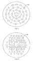
- the two-dimensional junction points 150" on the external surface of the electronic core 15 are arranged in a hexagonal grid form. As shown in FIG. 4 , the junction points are aligned along the dash lines. This alignment makes the junction points be arranged closely and thus the pitches between the junction points can be reduced as much as possible. Accordingly, the collimation accuracy is improved still further.
- FIG. 5 is a structural diagram showing a wristwatch 10' implemented according to another embodiment of the present invention.
- the wristwatch 10' further comprises an interposer 17, which is disposed between the electric driving component 14 and the two-dimensional junction points 150 on the external surface of the electronic core 15.
- the interposer 17 has conductive junction points distributed on the upper and lower surfaces thereof.
- the conductive junction points on the upper surface communicate with corresponding conductive junction points on the lower surface.
- the distribution of the conductive junction points of the interposer 17 is substantially in consistent with that of the junction points 150 on the external surface of the electronic core 15.
- the conductive junction points of the interposer 17 deviate from the junction points of the electronic core 15 along the horizontal direction for a short distance when the interposer 17 has been arranged in the wristwatch 10'.
- the arrangement of the interposer 17 can further avoid a collimation error occurred between the electric driving component 14 and the junction points 150 on the external surface of the electronic core 15.
- the pin of the electric driving component 14 When assembling the wristwatch, the pin of the electric driving component 14 is connected to any one point of a set of junction points (e.g., 8 junction points for a set). After that, the programmable logic unit and the multiplexers define the use of those junction points. In such a manner, the pin of the electric driving component 14 is able to be electrically connected to a time circuit inside the electronic core 15. In support of the position design with respect to the indicator 13, it is assumed that the pin of the electric driving component 14 is connected to a connecting point numbered as 3 on the right side of the multiplexer 21 during assembling the wristwatch.
- the present invention allows a wristwatch user to redefine or reassign the use of each junction point 150 after the wristwatch leaves the manufacturing factory.
- the wristwatch user can make the electric driving component 14 electrically connect to another physical junction point 150 corresponding to another circuit or a junction point 150 connected to the electric driving component 14 is redefined or reassigned to said another circuit.
- handheld devices such as smart phones and tablets
- the wristwatch user may communicate with the wristwatch (for example, through wireless communication).
- the electric driving component 14 of the present invention may be mechanically connected to the indicator 13 directly or indirectly.
- the electric driving component 14 has a driving shift (not labeled with a reference number), which is directly connected with the indicator 13. In such a manner, the electric driving component 14 can drive the indicator 13 directly.
- the electric driving component 14 has the driving shift and a transfer mechanism (not shown) mechanically connected to the driving shift. The driving shift is connected to the indicator 13 via the transfer mechanism. In such a manner, the electric driving component 14 drives the indicator 13 through the transfer mechanism.
- the logic component 31 can be implemented as a processor or a programmable IC.
- the memory component 32 may comprise a non-volatile memory (such as a NADA flash memory) and a synchronous dynamic random-access memory (SDRAM).
- the passive component 34 (such as a capacitor) may be coupled between the logic component 31 and the power management component 33.
- the power management component 33 handles the electrical power supply based on actual needs.
- the electronic core 15 of the present invention can become a universal electronic core for the wristwatch. It is convenient for the wristwatch manufacturers to achieve various wristwatch designs by adopting the universal electronic core, thereby shortening the product development cycle. Also, the present invention solves the traditional problem of the need to develop electronic cores in response to different wristwatch designs. Also, by utilizing the universal electronic core, the wristwatch assembling is simple and quick.
- each junction point 150 is defined or assigned (Step S18). Specifically speaking, the connection paths between the inner circuits of the electronic core 15 and the two-dimensional junction points 150 on the external surface of the electronic core 15 are assigned or defined such that the electric driving component 14 is electrically connected to a specific circuit in the electronic core 15. That is to say, the junction point connected to the electric driving component 14 is assigned to the specific circuit such that the specific circuit can drive or control the electric driving component 14. Finally, all the aforesaid components (such as the dial 12, the indicator 13, the electric driving component 14, and the electronic core 15) are packaged in the watchcase 11 to finish the manufacture of the wristwatch (Step S20).
- the electronic signals having opposite waveforms may be generated when the user rotates the electronic crown clockwise and counterclockwise. In such a manner, it is easily to control the hands on the clock to move in a clockwise direction and in a counterclockwise direction.
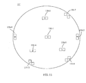
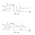
- an electronic signal detected by the detecting portion 442 is similar to the waveform shown on the right side of the dash line L in FIG. 14A (or in FIG. 14B ). That is, when the first sub portion 401 and the second sub portion 402 are parked at the second specific position, the detecting portion 442 detects a relatively weak signal and the voltage level of the detected signal is relatively small.
- the electronic core 15 can control different hands or indicators with different signal waveforms. For example, the position of the hour hand can be adjusted when the user pushes the rotating part 42 so as to make the rotating portion 441 park at the first specific position. The position of the minute hand can be adjusted when the user pushes the rotating part 42 so as to make the rotating portion 441 park at the second specific position.
- the first sub portion 401 and the second sub portion 402 are objects having different dielectric constants.
- the detecting portion 442 includes a capacitance detecting component for detecting a capacitance between two electrodes, for example. The capacitance may change due to different positions where the first sub portion 401 and the second sub portion 402 are located at.
- the detecting portion 401 detects different voltage levels of electronic signals as the capacitance is changed.
- the first sub portion 401 and the second sub portion 402 of the rotating portion 441 can be magnetic materials having distinct magnetic strength.
- the detecting portion 442 includes a conductive coil.
- the electronic crown described in above embodiments is also applicable to a wristwatch having a display (such as a liquid crystal display device) 51.
- the time relevant information is displayed on a screen of the display 51.
- the display 51 may display hands and time scales on the screen, or display the current time by digital numbers.
- the smart wristwatch may have other functions and may list these functions (e.g., items 53) or other settings on the screen of the display 51 by using a menu 52.
- the electronic crown 40 of the wristwatch can be used to switch the selection of the items 53 and confirm the selected item 53.
- the electronic crown 40 exports the electronic signals and the electronic signals are used to control the display 51 so as to switch or select the item 53 listed in the menu 52.
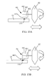
- the item 53 of the menu 52 moves to next position from top to bottom and the positions of the other items 53 are changed in the same manner, and the selected item 53 is enlarged as well.
- the electronic crown 40 is rotated in an opposite direction, the items 53 move from bottom to top, as shown in FIG. 15A .
- the items 53 of the menu 52 may move along a direction indicated by an arrow in FIG. 15B .
- the selected item 53 is confirmed and the function or setting represented by the selected item 53 is then executed.
Landscapes
- Physics & Mathematics (AREA)
- General Physics & Mathematics (AREA)
- Electric Clocks (AREA)
- Electromechanical Clocks (AREA)
Applications Claiming Priority (2)
| Application Number | Priority Date | Filing Date | Title |
|---|---|---|---|
| TW102116080A TWI454865B (zh) | 2013-05-06 | 2013-05-06 | 腕錶結構、腕錶用的電子機芯及腕錶的製造方法 |
| TW102148554A TWI494718B (zh) | 2013-12-26 | 2013-12-26 | 腕錶結構及腕錶用的電子機芯 |
Publications (2)
| Publication Number | Publication Date |
|---|---|
| EP2801870A2 true EP2801870A2 (fr) | 2014-11-12 |
| EP2801870A3 EP2801870A3 (fr) | 2016-01-27 |
Family
ID=50382302
Family Applications (1)
| Application Number | Title | Priority Date | Filing Date |
|---|---|---|---|
| EP14161613.6A Withdrawn EP2801870A3 (fr) | 2013-05-06 | 2014-03-25 | Structure de montre-bracelet, noyau électronique et procédé de fabrication de montre-bracelet |
Country Status (5)
| Country | Link |
|---|---|
| US (1) | US9256209B2 (fr) |
| EP (1) | EP2801870A3 (fr) |
| JP (1) | JP5782155B2 (fr) |
| KR (1) | KR101509435B1 (fr) |
| CN (1) | CN104142623A (fr) |
Families Citing this family (35)
| Publication number | Priority date | Publication date | Assignee | Title |
|---|---|---|---|---|
| US9753436B2 (en) | 2013-06-11 | 2017-09-05 | Apple Inc. | Rotary input mechanism for an electronic device |
| JP6345782B2 (ja) | 2013-08-09 | 2018-06-20 | アップル インコーポレイテッド | 電子デバイス用のタクタイルスイッチ |
| US10048802B2 (en) | 2014-02-12 | 2018-08-14 | Apple Inc. | Rejection of false turns of rotary inputs for electronic devices |
| US10190891B1 (en) | 2014-07-16 | 2019-01-29 | Apple Inc. | Optical encoder for detecting rotational and axial movement |
| KR102239316B1 (ko) | 2014-09-02 | 2021-04-13 | 애플 인크. | 웨어러블 전자 디바이스 |
| CN105676625B (zh) * | 2014-11-19 | 2018-05-04 | 昆达电脑科技(昆山)有限公司 | 手表装置 |
| WO2016141228A1 (fr) | 2015-03-05 | 2016-09-09 | Apple Inc. | Encodeur optique doté de propriétés optiques dépendant de la direction |
| JP6479997B2 (ja) | 2015-03-08 | 2019-03-06 | アップル インコーポレイテッドApple Inc. | 回転可能かつ並進可能な入力機構のための圧縮可能な封止 |
| US10018966B2 (en) | 2015-04-24 | 2018-07-10 | Apple Inc. | Cover member for an input mechanism of an electronic device |
| EP3156854A1 (fr) * | 2015-10-13 | 2017-04-19 | The Swatch Group Research and Development Ltd. | Montre-bracelet mecanique a laquelle est associee une fonction electronique |
| US9939785B2 (en) * | 2016-01-05 | 2018-04-10 | Seiko Instruments Inc. | Pointer driving motor unit, electronic device, and control method of pointer driving motor unit |
| JP6774298B2 (ja) * | 2016-01-05 | 2020-10-21 | セイコーインスツル株式会社 | 指針駆動用モータユニット、電子機器および指針駆動用モータユニットの制御方法 |
| US9891651B2 (en) | 2016-02-27 | 2018-02-13 | Apple Inc. | Rotatable input mechanism having adjustable output |
| US10551798B1 (en) | 2016-05-17 | 2020-02-04 | Apple Inc. | Rotatable crown for an electronic device |
| US10061399B2 (en) | 2016-07-15 | 2018-08-28 | Apple Inc. | Capacitive gap sensor ring for an input device |
| US10019097B2 (en) | 2016-07-25 | 2018-07-10 | Apple Inc. | Force-detecting input structure |
| US10664074B2 (en) | 2017-06-19 | 2020-05-26 | Apple Inc. | Contact-sensitive crown for an electronic watch |
| US10962935B1 (en) | 2017-07-18 | 2021-03-30 | Apple Inc. | Tri-axis force sensor |
| US10474108B2 (en) | 2017-09-27 | 2019-11-12 | Apple Inc. | Magnetic sensor array for crown rotation |
| CN108021072B (zh) * | 2018-01-04 | 2023-09-19 | 福州大学 | 一种基于3d微功耗磁力计的智能旋钮系统 |
| US11107281B2 (en) | 2018-05-18 | 2021-08-31 | Valeo Comfort And Driving Assistance | Shared environment for vehicle occupant and remote user |
| US11360440B2 (en) | 2018-06-25 | 2022-06-14 | Apple Inc. | Crown for an electronic watch |
| US11561515B2 (en) | 2018-08-02 | 2023-01-24 | Apple Inc. | Crown for an electronic watch |
| US11181863B2 (en) | 2018-08-24 | 2021-11-23 | Apple Inc. | Conductive cap for watch crown |
| US12259690B2 (en) | 2018-08-24 | 2025-03-25 | Apple Inc. | Watch crown having a conductive surface |
| CN209560398U (zh) | 2018-08-24 | 2019-10-29 | 苹果公司 | 电子表 |
| US11194298B2 (en) | 2018-08-30 | 2021-12-07 | Apple Inc. | Crown assembly for an electronic watch |
| CN209625187U (zh) | 2018-08-30 | 2019-11-12 | 苹果公司 | 电子手表和电子设备 |
| US11194299B1 (en) | 2019-02-12 | 2021-12-07 | Apple Inc. | Variable frictional feedback device for a digital crown of an electronic watch |
| US11550268B2 (en) | 2020-06-02 | 2023-01-10 | Apple Inc. | Switch module for electronic crown assembly |
| US11924393B2 (en) | 2021-01-22 | 2024-03-05 | Valeo Comfort And Driving Assistance | Shared viewing of video among multiple users |
| US12092996B2 (en) | 2021-07-16 | 2024-09-17 | Apple Inc. | Laser-based rotation sensor for a crown of an electronic watch |
| US12189347B2 (en) | 2022-06-14 | 2025-01-07 | Apple Inc. | Rotation sensor for a crown of an electronic watch |
| US11983822B2 (en) | 2022-09-02 | 2024-05-14 | Valeo Comfort And Driving Assistance | Shared viewing of video with prevention of cyclical following among users |
| US12596334B2 (en) | 2023-02-07 | 2026-04-07 | Apple Inc. | Crown for an electronic watch |
Family Cites Families (21)
| Publication number | Priority date | Publication date | Assignee | Title |
|---|---|---|---|---|
| JPS5667779A (en) * | 1979-11-06 | 1981-06-08 | Seiko Epson Corp | Crystal watch |
| DE8136793U1 (de) * | 1981-12-17 | 1983-02-24 | Gebrüder Junghans GmbH, 7230 Schramberg | Uhrwerk mit Leiterplatte für eine elektronische Antriebssteuerschaltung und Trägerplatte für das Räder- und Zeigerwerk zwischen zwei Gehäuseschalen |
| JPS59104586A (ja) * | 1982-12-07 | 1984-06-16 | Seiko Epson Corp | コンビネ−シヨン時計のモジユ−ル構造 |
| CH653846GA3 (fr) * | 1983-12-06 | 1986-01-31 | ||
| DE3531235A1 (de) | 1984-09-25 | 1986-04-03 | VEB Kombinat Robotron, DDR 8010 Dresden | Kompaktschaltungsanordnung und verfahren zur behuegelung |
| GB2203270B (en) * | 1987-03-05 | 1991-09-11 | Seiko Epson Corp | Timepiece assembly. |
| US5113381A (en) * | 1989-04-19 | 1992-05-12 | Seiko Epson Corporation | Multifunction electronic analog timepiece |
| JP2500513B2 (ja) | 1992-11-10 | 1996-05-29 | 株式会社精工舎 | 時計機械体 |
| JP2000124259A (ja) | 1998-10-12 | 2000-04-28 | Sony Corp | Icチップ、半導体装置、及び、半導体装置の製造方法 |
| JP2003110060A (ja) | 2001-09-28 | 2003-04-11 | Sony Corp | インターポーザ基板、その製造方法、および半導体装置 |
| JP2004020422A (ja) * | 2002-06-18 | 2004-01-22 | Seiko Instruments Inc | 規正レバーを有するアナログ電子時計 |
| CH697272B1 (fr) * | 2002-07-19 | 2008-07-31 | Asulab Sa | Pièce d'horlogerie électronique comportant un mode de jeu. |
| US7336268B1 (en) * | 2002-10-30 | 2008-02-26 | National Semiconductor Corporation | Point-to-point display system having configurable connections |
| CN1698019A (zh) * | 2003-02-21 | 2005-11-16 | 精工爱普生株式会社 | 驱动装置、计时装置和计时装置的控制方法 |
| US20040233794A1 (en) * | 2003-02-21 | 2004-11-25 | Seiko Epson Corporation | Timepiece driving apparatus and time calculating apparatus |
| JP4737637B2 (ja) * | 2004-12-15 | 2011-08-03 | セイコーインスツル株式会社 | 複数のムーブメントレイアウトを実現できる多機能時計 |
| US7859951B2 (en) * | 2005-06-17 | 2010-12-28 | Timex Group B.V. | Universal electronic device module configuration |
| ATE475119T1 (de) * | 2006-11-13 | 2010-08-15 | Eta Sa Mft Horlogere Suisse | Anordnung zur mechanischen verbindung eines mems- mikromotors mit einem uhrrädchen und diese anordnung umfassende uhr |
| US20100220559A1 (en) * | 2009-02-27 | 2010-09-02 | Galie Louis M | Electromechanical Module Configuration |
| US8389337B2 (en) | 2009-12-31 | 2013-03-05 | Intel Corporation | Patch on interposer assembly and structures formed thereby |
| TWI548042B (zh) | 2013-04-23 | 2016-09-01 | 巨擘科技股份有限公司 | 電子系統及其核心模組 |
-
2014
- 2014-02-14 CN CN201410050653.0A patent/CN104142623A/zh active Pending
- 2014-02-24 US US14/188,004 patent/US9256209B2/en not_active Expired - Fee Related
- 2014-03-25 EP EP14161613.6A patent/EP2801870A3/fr not_active Withdrawn
- 2014-04-16 KR KR20140045238A patent/KR101509435B1/ko not_active Expired - Fee Related
- 2014-04-16 JP JP2014084490A patent/JP5782155B2/ja not_active Expired - Fee Related
Non-Patent Citations (1)
| Title |
|---|
| None |
Also Published As
| Publication number | Publication date |
|---|---|
| CN104142623A (zh) | 2014-11-12 |
| KR20140131864A (ko) | 2014-11-14 |
| US9256209B2 (en) | 2016-02-09 |
| JP5782155B2 (ja) | 2015-09-24 |
| EP2801870A3 (fr) | 2016-01-27 |
| KR101509435B1 (ko) | 2015-04-14 |
| JP2014219391A (ja) | 2014-11-20 |
| US20140328148A1 (en) | 2014-11-06 |
Similar Documents
| Publication | Publication Date | Title |
|---|---|---|
| US9256209B2 (en) | Wristwatch structure, electronic core for wristwatch, and method for manufacturing wristwatch | |
| US9223296B2 (en) | Wristwatch structure, electronic crown for wristwatch, and wristwatch having display | |
| US7406003B2 (en) | Multifunctional timepiece module with application specific printed circuit boards | |
| KR20160070723A (ko) | 외부정보에 의해 제어되는 다기능 휴대용 장치 | |
| US20240103449A1 (en) | Dual Display Timer and Its Control Method | |
| JP2008544241A (ja) | 汎用電子装置のモジュール構成 | |
| CN102298312A (zh) | 多指针电子钟表 | |
| US20180196397A1 (en) | Multifunctional system for a wristwatch | |
| CN102298313B (zh) | 多指针电子设备 | |
| CN1028568C (zh) | 多功能的指针式时计 | |
| TWI556074B (zh) | 腕錶結構 | |
| CN203535384U (zh) | 具有双向运动的指针的手表 | |
| TWI494718B (zh) | 腕錶結構及腕錶用的電子機芯 | |
| TWI454865B (zh) | 腕錶結構、腕錶用的電子機芯及腕錶的製造方法 | |
| CN205787632U (zh) | 一种智能手表 | |
| JP2014182047A (ja) | アナログ電子時計 | |
| JP6354371B2 (ja) | 回路モジュール、時計用ムーブメント、電子時計、および回路モジュールの配線方法 | |
| CN204203643U (zh) | 多功能机动石英时计 | |
| JP4228708B2 (ja) | 多機能時計 | |
| JP3631381B2 (ja) | 複合表示式電子時計 | |
| JP6586887B2 (ja) | 電子時計 | |
| JP2000147156A (ja) | 計時装置 |
Legal Events
| Date | Code | Title | Description |
|---|---|---|---|
| PUAI | Public reference made under article 153(3) epc to a published international application that has entered the european phase |
Free format text: ORIGINAL CODE: 0009012 |
|
| 17P | Request for examination filed |
Effective date: 20140325 |
|
| AK | Designated contracting states |
Kind code of ref document: A2 Designated state(s): AL AT BE BG CH CY CZ DE DK EE ES FI FR GB GR HR HU IE IS IT LI LT LU LV MC MK MT NL NO PL PT RO RS SE SI SK SM TR |
|
| AX | Request for extension of the european patent |
Extension state: BA ME |
|
| PUAL | Search report despatched |
Free format text: ORIGINAL CODE: 0009013 |
|
| AK | Designated contracting states |
Kind code of ref document: A3 Designated state(s): AL AT BE BG CH CY CZ DE DK EE ES FI FR GB GR HR HU IE IS IT LI LT LU LV MC MK MT NL NO PL PT RO RS SE SI SK SM TR |
|
| AX | Request for extension of the european patent |
Extension state: BA ME |
|
| RIC1 | Information provided on ipc code assigned before grant |
Ipc: G04C 3/12 20060101AFI20151223BHEP Ipc: G04G 17/04 20060101ALI20151223BHEP Ipc: G04C 3/00 20060101ALI20151223BHEP |
|
| R17P | Request for examination filed (corrected) |
Effective date: 20160726 |
|
| RBV | Designated contracting states (corrected) |
Designated state(s): AL AT BE BG CH CY CZ DE DK EE ES FI FR GB GR HR HU IE IS IT LI LT LU LV MC MK MT NL NO PL PT RO RS SE SI SK SM TR |
|
| STAA | Information on the status of an ep patent application or granted ep patent |
Free format text: STATUS: THE APPLICATION IS DEEMED TO BE WITHDRAWN |
|
| 18D | Application deemed to be withdrawn |
Effective date: 20171003 |