EP2801873B1 - Dispositif de test d'un appareil de commande virtuel - Google Patents
Dispositif de test d'un appareil de commande virtuel Download PDFInfo
- Publication number
- EP2801873B1 EP2801873B1 EP14153755.5A EP14153755A EP2801873B1 EP 2801873 B1 EP2801873 B1 EP 2801873B1 EP 14153755 A EP14153755 A EP 14153755A EP 2801873 B1 EP2801873 B1 EP 2801873B1
- Authority
- EP
- European Patent Office
- Prior art keywords
- virtual
- control device
- interface
- unit
- pin
- Prior art date
- Legal status (The legal status is an assumption and is not a legal conclusion. Google has not performed a legal analysis and makes no representation as to the accuracy of the status listed.)
- Active
Links
Images


Classifications
-
- G—PHYSICS
- G05—CONTROLLING; REGULATING
- G05B—CONTROL OR REGULATING SYSTEMS IN GENERAL; FUNCTIONAL ELEMENTS OF SUCH SYSTEMS; MONITORING OR TESTING ARRANGEMENTS FOR SUCH SYSTEMS OR ELEMENTS
- G05B17/00—Systems involving the use of models or simulators of said systems
- G05B17/02—Systems involving the use of models or simulators of said systems electric
-
- G—PHYSICS
- G05—CONTROLLING; REGULATING
- G05B—CONTROL OR REGULATING SYSTEMS IN GENERAL; FUNCTIONAL ELEMENTS OF SUCH SYSTEMS; MONITORING OR TESTING ARRANGEMENTS FOR SUCH SYSTEMS OR ELEMENTS
- G05B15/00—Systems controlled by a computer
- G05B15/02—Systems controlled by a computer electric
-
- G—PHYSICS
- G05—CONTROLLING; REGULATING
- G05B—CONTROL OR REGULATING SYSTEMS IN GENERAL; FUNCTIONAL ELEMENTS OF SUCH SYSTEMS; MONITORING OR TESTING ARRANGEMENTS FOR SUCH SYSTEMS OR ELEMENTS
- G05B23/00—Testing or monitoring of control systems or parts thereof
- G05B23/02—Electric testing or monitoring
-
- G—PHYSICS
- G06—COMPUTING OR CALCULATING; COUNTING
- G06F—ELECTRIC DIGITAL DATA PROCESSING
- G06F30/00—Computer-aided design [CAD]
- G06F30/20—Design optimisation, verification or simulation
Definitions
- the invention relates to a test device for testing at least part of a virtual control device with a simulation environment in a simulator, comprising the virtual control device and the simulation environment, wherein the virtual control device comprises at least one software component with at least one external data interface, wherein the simulation environment at least one data interface for at least indirect data exchange with the virtual control device comprises.
- the test of the serial controller used in the final product is the endpoint of a plurality of upstream development steps of a controller to be implemented on the controller, which development steps are usually described by the so-called V-model or V-cycle.
- V-model or V-cycle development steps are usually described by the so-called V-model or V-cycle.
- the control is implemented on the later in the series control unit probably actually used in the target processor.
- the target hardware thus approaches the serial controller in this step, but is not identical to the serial controller.
- the serial control unit which is usually only available at a late stage of development, is checked by means of a hardware-in-the-loop test (HIL).
- HIL hardware-in-the-loop test
- the serial control device physically present in this step is connected here by means of its physical control device interface to a powerful simulator.
- the simulator simulates the required sizes of the series control unit to be tested and exchanges input and output variables with the series control unit.
- the pins of the physical control unit interface of the serial controller are connected to the simulator via a cable harness.
- the tested in the context of HIL simulation series control device is ultimately installed in the "real" target system, so for example in a motor vehicle and tested in the real physical environment that has been simulated before in the simulation environment only.
- the aforementioned software components are - at least partially - under consideration simulated in a simulator (dSPACE Catalog 2013: "SystemDesk V-ECU Generation Modules” and "VEOS”).
- the simulator can be one or more specialized computers, for example in the form of an HIL test stand, but a commercially available PC can also be used as the simulator.
- the virtual controller interacts with the simulation environment also present in the simulator. The interaction takes place by exchanging data via the at least one external data interface of a software component of the virtual control device and a data interface of the simulation environment.
- the simulation environment must in each case adapt to the external data interface of the software components of the virtual control device as a function of the software components reproduced in the virtual control device. Any change in the virtual controller that involves a software component having an external data interface will inevitably entail a change in the simulation environment and data interface of the simulation environment, which is labor intensive and causes errors in the development process. It is also disadvantageous that the simulation environment adapted to a specific virtual control unit in the context of the HIL simulation-that is to say when the control unit is physically present and no longer only virtually present-can frequently not be used directly, since the provision of such a deployment requires Pin-related sizes of the physical ECU interface to the data interface of the simulation environment is not given. This fact virtually prevents a practicable realization of the previously mentioned electrical fault simulation in connection with virtual control devices.
- the previously derived object is initially and essentially achieved by supplementing the test device with a virtual ECU pin unit which has at least one virtual ECU interface and by means of the virtual ECU interface at least with the outer data interface of the software device. Component of the virtual controller is connected.
- the virtual controller pin unit has at least one simulation environment interface, wherein the virtual controller pin unit means the simulation environment interface is at least indirectly connected to the data interface of the simulation environment.
- the virtual control unit pin unit has at least one virtual control unit pin which corresponds to a pin of the physical interface of a real ECU to be simulated, wherein a virtual physical control unit signal can be transmitted via the virtual control unit pin in data form describes the physical controller signals at the corresponding pin of the physical interface.
- a virtual influencing unit has at least a first interface and a second interface, wherein the virtual influencing unit by means of the first interface at least with the virtual ECU pin of the ECU Pin unit is connected and connected to the second interface with the data interface of the simulation environment, the virtual influencing unit via the first interface and / or the second interface outputs an affected virtual physical controller signal.
- the two essential points of the test device according to the invention thus lie in the virtual control unit pin unit, which provides at least one virtual control device pin, which corresponds to a pin of the physical interface of a real ECU to be simulated and in the provision of the virtual influencing device.
- the inventively provided virtual ECU pin unit mediates between the virtual controller and the simulation environment, which basically opens up the possibility to leave the simulation environment and its data interface unchanged even with a change of the virtual controller.
- the additional provision of a virtual ECU pins also brings with it the possibility, the virtual Defining the image of the interface that the real ECU must also have, namely the physical interface of the real ECU. This opens up a pin-related definition and handling of the interface between the virtual control device and the simulation environment on the simulator.
- a virtual physical control unit signal in that this is not the true physical control unit signal of the real control unit, ie voltages, currents, terminal resistances, but these physical quantities are calculated and exchanged as appropriate data in terms of value.
- a virtual physical controller signal in data form describes the physical controller signals at the corresponding pin of the physical interface. If only more abstract software layers are mapped in the virtual control device, for example the application software or the runtime environment, then the external data interface of the virtual control device can only be abstractly functional, but can not provide a signal-like simulation of the real control device.
- a component of the application software delivers a pressure value or a temperature value (for example 950 bar, 275 ° C.) but no corresponding electrically coded variable which is exchanged in the real control unit via pins of the physical interface, for example in the form of a voltage ( eg 0 to 10 V), in the form of a current (eg 2 to 20 mA interface) or in the form of a modulated signal
- the virtual controller pin unit can now close this gap by connecting it to at least a virtual control device pin exactly such a virtual physical control device signal, ie the value of the corresponding physical physical control device signal transmits.
- the signal flow direction reverse to the previous example is also possible, for example, by retrieving a virtual physical control device signal from the virtual control device pin and transmitting it in the direction of the virtual control device.
- the virtual influencing unit has an affected virtual physical control device signal via one of its interfaces why the virtual influencing unit also basically has the ability to influence a virtual physical control device signal, usually in the sense of simulating an electrical fault.
- the influencing unit independently provides an affected virtual physical control device signal, for example because the user has stored corresponding configuration data in the influencing unit.
- Such a configuration could be, for example, that a specific terminal of the first interface and / or the second interface of the virtual influencing unit is fixed to the electrical ground potential. In this case, no further information is required to determine the affected virtual physical controller signal, in particular no information from the simulation environment.
- An electrical fault simulation can then consist in that the predetermined and therefore also influenced virtual physical control device signal is transmitted via the first interface of the influencing unit to the virtual control unit pin unit.
- the influencing unit may also be connected via its interfaces to more than one virtual ECU pin of the virtual controller pin unit.
- any affected virtual physical controller signal it is not necessary for any affected virtual physical controller signal to be output or transmitted over each of these ports, in other words, not every channel of the virtual interference unit needs to be actually affected; virtual physical controller signals, for example, may also be required be transferred unaffected.
- the great advantage of the test device according to the invention is that complete consistency with regard to the configuration, simulation and the test is achieved between the fault simulation in the case of real control devices and the fault simulation in the case of virtual control devices. Due to the pin-oriented design of the interfaces, the simulation environment - at least insofar as it communicates via virtual ECU pins of the virtual control unit pin unit - can be used without further adaptation with the hardware-implemented series control unit. With regard to the conceivable embodiments and embodiments of the virtual control unit pin unit are numerous variants in the priority application EP 13/166604 described. For example, it is provided that the simulation environment interface of the virtual control unit pin unit has at least one virtual control device pin, so that virtual physical control device signals can also be transmitted via the data interface of the simulation environment.
- the simulation environment interface of the virtual control unit pin unit is formed entirely from virtual control device pins, so that exclusively virtual physical control device signals are transmitted via the data interface of the simulation environment.
- the simulation environment interface of the virtual control unit pin unit does not have a virtual control unit pin, so that the virtual control unit pin unit establishes a direct connection between the virtual control unit and the simulation environment and the virtual control unit pin Unit having at least one virtual controller pin outside the simulation environment interface.
- the influencing unit calculates an influenced virtual physical control device signal based on information from the simulation environment and transmits it via the first interface to the virtual control device pin unit.
- an affected virtual physical control device signal can be defined in the influencing unit - thus no information from the simulation environment is required for calculating this influenced virtual physical control device signal - and other affected virtual physical controller signal can be calculated using information from the simulation environment or even from the virtual controller in the influencing unit.
- the influencing unit receives a virtual physical control device signal from the virtual control unit pin unit and calculates an influenced virtual physical control device signal from the received virtual physical control device signal, in particular the influenced virtual physical control device signal via the second interface to the simulation environment.
- the influencing unit receives a virtual physical control device signal from the virtual control unit pin unit and calculates an influenced virtual physical control device signal from the received virtual physical control device signal, in particular the influenced virtual physical control device signal via the second interface to the simulation environment.
- an input variable is influenced and influenced in accordance with a specific functionality. It is conceivable, for example, the falsified transmission of a voltage value due to a - possibly non-linear elements having - simulated voltage divider.
- the virtual influencing unit of the virtual control unit pin unit and the simulation environment is interposed, so that an indirect connection with the outer data interface of the software component of the virtual controller is and / or so that a Connected to the parts of the data interface of the simulation environment that correspond to the outer data interface of the software component of the virtual controller.
- all signals pass through the virtual influencing unit, not just the signals that are conveyed via virtual control device pins of the virtual control unit pin unit.
- the virtual influencing unit not only has the pin-oriented signals, but also functional signals that are exchanged between the external data interface of the software components of the virtual ECU and the simulation environment. This variant makes possible in certain cases a more efficient simulation, in particular a more efficient fault simulation within the virtual influencing unit.
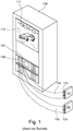
- Fig. 1 first a known from the prior art test setup according to the principle of the hardware-in-the-loop tests shown.
- the real control units 101, 102 are connected to their physical interfaces 103, 104 and via harnesses 105, 106 with corresponding I / O interfaces 107, 108 of a simulator 109 connected.
- the simulator 109 itself also has a simulation environment 110 which relates to a mathematical environment model which simulates the surroundings of the control device, for example a vehicle model.
- the environment model is indicated by the block diagram 111.
- Test setup shown results only when the production ECUs 101, 102 are present at the end of the development process. Only in this situation, it is possible to test the software components of the real ECUs 101, 102 in interaction with the simulator.
- the I / O interfaces 107, 108 also allow the simulation of electrical faults, ie, they have an electronics for fault connection, which is referred to in practice as a "failure insertion unit".
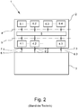
- FIGS. 2 to 7 In order to enable the components of the software to be operated later on the real control devices 101, 102 even in preceding steps of the controller development, the in Fig. 2 have been introduced schematically and known from the prior art test devices 1, which allow the test of a virtual controller 2 with a simulation environment 3. Such test devices 1 are operated on a simulator, which in the FIGS. 2 to 7 is not explicitly shown.
- the virtual controller 2 comprises a plurality of software components 4, 5, 6 belonging to different abstract software layers.
- the different software layers are in Fig. 2 indicated by horizontal lines a, b.
- the software components 6.1, 6.2, 6.3 and 6.4 are components of the application layer in which software is implemented completely independently of the machine, that is to say independently of the target platform. All underlying software layers are closer to hardware.
- the software component 5 comprises in the illustrated embodiment, the runtime environment, and the software components 4.1, 4.2 and 4.3 include platform-independent as well as platform-dependent basic software, for example in the form of the operating system and in the form of various communication services.
- the software components 4, 5, 6 are software components that are to be used later on the real control unit also, the software components are operated in the context of a virtual control unit 2 but on a simulator, the device is perfect is different from the later real controller.
- the software components 4 are in connection with the simulation environment 3.
- the software components 4 have external data interfaces 7.1, 7.2 and 7.3.
- This in FIG. 2 represented virtual control unit 2 is modeled very close to hardware. This is not always the case in practice; in another modeling of the virtual control device 2, for example, only the software components 6.1 to 6.4 could occur at the application level, so that such a virtual control device did not have the software components 4 and 5.
- the interfaces of the software components 6 would be the external data interfaces because they would have to be in connection with the simulation environment 3 in order to be able to ensure a data exchange.
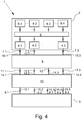
- a test device 1 is shown with a virtual control unit 2 and with a simulation environment 3, but now also between a virtual control unit 2 and the simulation environment 3 mediating virtual ECU pin unit 9 is provided.
- the virtual control unit pin unit 9 has virtual control unit interfaces 10.1, 10.2, by means of which the virtual control unit pin unit 9 is connected to the outer data interfaces 7.1, 7.2 of the software components 4.1, 4.2 of the virtual control unit 2.
- the virtual control unit pin unit 9 further has simulation environment interfaces 11.1, 11.2 and is connected to the data interfaces 8.1, 8.2 of the simulation environment 3 by means of the simulation environment interfaces 11.1, 11.2. Since these are all components that are realized on a computer, the interfaces are not physically understandable, they are to be understood functionally in the sense that they are beyond the created ones Interfaces - however, data can be exchanged and made available.
- the virtual control unit pin unit 9 also has a virtual control unit pin 12, which corresponds to a pin of the physical interface of a real ECU to be simulated. Via the virtual control device pin 12, a virtual physical control device signal is transferable. With the virtual control device pin 12 so a pin of a physical interface of a real controller is simulated. Accordingly, in the form of data, such quantities are transmitted which correspond to physical control device signals of this pin.
- the virtual control unit pin 12 thus enables a view of the virtual control unit 2, which is predetermined by the physical signal forms of the physical physical interfaces of the real ECU to be simulated.
- the virtual control unit pin unit 9 allows the signal view to the virtual control unit 2, wherein this signal can not be used in different ways.
- the test device 1 also has a virtual influencing unit 13 with a first interface 14 and a second interface 15, wherein the virtual influencing unit 13 is connected by means of the first interface 14 to the virtual control unit pin 12 of the control unit pin unit 9 is.
- the virtual influencing unit 13 With the second interface 15, the virtual influencing unit 13 is connected to the data interface 8.3 of the simulation environment 3.
- the virtual influencing unit 13 is designed such that it can exchange, in particular output, an influenced virtual physical control device signal via the first interface 14 and / or the second interface 15; Accordingly, the data interface 8.3 of the simulation environment 3 is pin-oriented and not (only) functionally designed. In other words, the virtual influencing unit 13 serves to introduce an error injection into the signal path.
- An advantage of the illustrated approach is that the configuration of the electrical fault simulation in the virtual influencing unit 13 in the various stations of the ECU test can be used regardless of whether the virtual controller 2 or a real controller is being tested.
- the virtual influencing unit can also be connected to the external data interface 7 of the virtual control device 2, for example to use functional information for fault simulation.
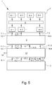
- a test device 1 is shown, in which the virtual control unit 2, the virtual control unit pin unit 9, the virtual influencing unit 13 and the simulation environment 3 are connected to each other in a modified manner.
- the virtual influencing unit 13 of the virtual control unit pin unit 9 and the simulation environment 3 is interposed, so that an indirect connection with the outer data interface 7.1, 7.2, 7.3 of the software components 4.1, 4.2, 4.3 of the virtual control unit 2 is ,
- the virtual control unit pin unit 9 is furthermore connected indirectly to the data interface 8 of the simulation environment 3 via the virtual influencing unit 13.
- the advantage of this variant is the fact that the virtual influencing unit 13 not only receives virtual physical control unit signals from the virtual influencing unit 13, but also receives pin-related - ie purely functional - signals from the software components, for example for an electrical fault simulation in the virtual influencing unit 13 can be used.
- the virtual influencing unit 13 is in the embodiment according to Fig. 4 capable of calculating an affected virtual physical controller signal based on information from the outer data interface 7 of the software components 4.1, 4.2, 4.3 of the virtual controller 2, just as the virtual controller 13 is capable of computing an affected virtual one to calculate physical control device signal based on information from the parts of the data interface 8 of the simulation environment 3, which correspond to the outer data interface 7 of the software components 4.1, 4.2, 4.3 of the virtual control device 2.
- the illustrated virtual influencing units 13 are configured to influence an affected virtual physical controller signal to emulate an electrical fault at one calculate virtual ECU pin 12.
- the virtual influencing units 13 output at an affected virtual control unit pin 12 a voltage value which corresponds to a short circuit to ground, supply voltage or another external electrical potential.
- the virtual influencing units 13 output the same voltage value as an affected virtual control device signal on both virtual ECU pins concerned.
- the virtual influencing units 13 exchange values intended for different virtual control device pins ("crossed wire") and output them as influenced virtual physical control unit signals.
- the virtual influencing units 13 simulate an open virtual control device pin by specifying an electrical resistance value at this virtual control device pin.
- the embodiment according to Fig. 5 differs from the embodiment according to Fig. 4 in that the virtual influencing unit 13 has a further interface 16 by means of which the virtual influencing unit 13 can be preset externally by electrical error signals. These error signals may be fixed in the specification of virtual electrical potentials, but it is also possible to transmit variable virtual electrical error signals to the virtual influencing unit 13.
- the virtual controller pin unit 9 and the virtual influencing unit 13 are realized in a common component, the virtual controller pin and the first interface of the virtual influencing unit 13 are functionally realized in the common component.
- the example makes it clear that the different units of the test device 1 and their interfaces are to be understood functionally and are not bound to the realization in separate or common software modules.
- the simulation environment 3 can be used in any case in the transition from the virtual test to the real test in an HIL simulator, which would otherwise not be possible .
- further data channels (not shown here) between the simulation environment 3 and the virtual control unit 2 can be realized, so that the simulation environment 3 can influence the virtual control unit 2; these data channels and the ports through which these data channels are routed then have no correspondence to data channels and pins of the real controller.
- tasks on the virtual controller 2 could be triggered out of the simulation environment via such additional data channels; this depends on the scope of the simulation environment 3.
- Fig. 7 symbolically represented in the virtual influencing unit 13 is a possible realization of a functionality which serves to activate a virtual electrical fault.
- the connections 12.2, 12.3 of the virtual control unit pin unit 9 are virtual control device pins 12 of a CAN bus. These connections are symbolically ground through the virtual influencing unit 13 and forwarded via the connections 15.1, 15.2 of the second interface of the virtual influencing unit 13 to the simulation environment 3.
- the simulation environment 3 also has symbolically the lines of the virtual CAN bus.
- the virtual influencing unit 13 has virtual electrical fault lines 17, 18, wherein the virtual electrical fault lines 17, 18 are connectable to terminals of the first interface 14 and / or to terminals of the second interface 15.
- the connectivity is realized by the switches s1 to s6. This in FIG.
- switching network is functionally and vividly the possibility of fault connection in the virtual influencing unit 13 again.
- This functionality is actually implemented in software so that switches and ports are mapped by variables, with values associated with these variables leading to a corresponding mapping of fault signals to nodes of the network.
- the virtual electrical fault lines 17, 18 are subjected to virtual physical quantities, in this case with the electrical potentials GND and FAIL.
- the virtual physical quantities are electrical currents or electrical resistances.
- the idea always consists in the fact that the applied virtual physical quantity also acts as a default for the connected connections of the first interface 14 and / or for the connected connections of the second interface 15. As already mentioned, these must not only be static virtual physical quantities, but may also be time-variable virtual physical quantities.
- the virtual control unit pin unit 13 is designed such that it generates program code for influencing the virtual control unit signals and / or for determining the virtual control unit signals.
- the program code does not have to be specified by the user of the test device, but rather that a possible functionality for error simulation can be modeled, for example, by a graphical editor - for example in the form of a FIG. 7 shown switching network - so that the potentially error-prone step of transferring the functionality into program code by the user of the test facility deleted.
Landscapes
- Engineering & Computer Science (AREA)
- Physics & Mathematics (AREA)
- General Physics & Mathematics (AREA)
- Automation & Control Theory (AREA)
- General Engineering & Computer Science (AREA)
- Theoretical Computer Science (AREA)
- Computer Hardware Design (AREA)
- Evolutionary Computation (AREA)
- Geometry (AREA)
- Debugging And Monitoring (AREA)
- Chemical & Material Sciences (AREA)
- Chemical Kinetics & Catalysis (AREA)
- Electrochemistry (AREA)
- Health & Medical Sciences (AREA)
- Life Sciences & Earth Sciences (AREA)
- Analytical Chemistry (AREA)
- Biochemistry (AREA)
- General Health & Medical Sciences (AREA)
- Immunology (AREA)
- Pathology (AREA)
Claims (12)
- Dispositif de test (1) pour tester au moins une partie d'un appareil de commande fictif (2) avec un simulateur, comportant un environnement de simulation (3), le dispositif de test (1) comportant l'appareil de commande fictif (2) et l'environnement de simulation (3), dans lequel l'appareil de commande fictif (2) comporte au moins une composante de logiciel (4, 5, 6) avec au moine une interface de données externe (7), dans lequel l'environnement de simulation (3) comporte au moins une interface de données (8) pour au moins l'échange de données indirecte avec l'appareil de commande fictif (2),
caractérisé en ce que
une unité de broche d'appareil de commande fictive (9) comporte au moins une interface d'appareil de commande fictive (10) et elle est reliée avec au moins l'interface de données externe (7) de la composante de logiciel (4) de l'appareil de commande fictif (2) via l'interface d'appareil de commande fictive (10),
l'unité de broche d'appareil de commande fictive (9) comporte au moine une interface d'environnement de simulation (11) et elle est reliée au moins indirectement avec l'interface de données (8) de l'environnement de simulation (3) via l'interface d'environnement de simulation,
l'unité de broche d'appareil de commande fictive (9) comporte au moins une broche d'appareil de commande fictive (12), qui correspond à une broche de l'interface physique d'un appareil de commande réel devant être simulé, sachant qu'il est transmissible, via la broche d'appareil de commande fictive (12), un signal d'appareil de commande physique fictif qui, sous forme de données, décrit les signaux d'appareil de commande physique à la broche correspondante de l'interface physique, et
une unité d'influence fictive (13) comporte au moins une première interface (14) et une seconde interface (15) et est reliée via la première interface (14) avec au moins la broche d'appareil de commande fictive (12) de l'unité de broche d'appareil de commande fictive (9) et est reliée via la seconde interface (15) avec l'interface de données (8) de l'environnement de simulation (3), sachant que l'unité d'influence fictive (13) émet via la première interface (14) et/ou la seconde interface (15) un signal d'appareil de commande fictif physique influencé. - Dispositif de test (1) selon la revendication 1, caractérisé en ce que l'unité d'influence (13) met à disposition automatiquement un signal d'appareil de commande fictif physique influencé, en particulier sans informations provenant de l'environnement de simulation (3), et le transmet via la première interface (14) à l'unité de broche d'appareil de commande fictive (9) .
- Dispositif de test (1) selon la revendication 1 ou 2, caractérisé en ce que l'unité d'influence (13) calcule sur la base d'informations provenant de l'environnement de simulation (3) un signal d'appareil de commande fictif physique influencé, et le transmet via la première interface (14) à l'unité de broche d'appareil de commande fictive (9).
- Dispositif de test (1) selon l'une des revendications 1 à 3, caractérisé en ce que l'unité d'influence fictive (13) reçoit de l'unité de broche d'appareil de commande fictive (9) un signal d'appareil de commande fictif physique et, à partir du signal d'appareil de commande fictif physique reçu, calcule un signal d'appareil de commande fictif physique influencé, en particulier, délivre le signal d'appareil de commande fictif physique influencé à l'environnement de simulation (3) via la seconde interface (15) .
- Dispositif de test (1) selon l'une des revendications 1 à 4, caractérisé en ce que l'unité d'influence fictive (13) est intercalée entre l'unité de broche d'appareil de commande fictive (9) et l'environnement de simulation (3), de sorte qu'il existe une liaison indirecte avec l'interface de données externe (7) de la composante de logiciel (4, 5, 6) de l'appareil de commande fictif (2) et/ou de sorte qu'il soit établi une liaison avec les parties de l'interface de donnée (8) de l'environnement de simulation (3) qui correspondent avec l'interface de données externe (7) de la composante de logiciel (4, 5, 6) de l'appareil de commande fictif (2) .
- Dispositif de test selon la revendication 5, caractérisé en ce que l'unité d'influence fictive (13) calcul un signal d'appareil de commande fictif physique influencé sur la base d'informations provenant de l'interface de données externe (7) de la composante de logiciel (4, 5, 6) de l'appareil de commande fictif (2) et/ou sur la base d'informations provenant des parties de l'interface de données (8) de l'environnement de simulation (3), qui correspondent avec l'interface de données externe (7) de la composante de logiciel (4, 5, 6) de l'appareil de commande fictif (2) .
- Dispositif de test (1) selon l'une des revendications 1 à 6, caractérisé en ce que l'unité d'influence fictive (13) calcule un signal d'appareil de commande fictif physique influencé en vue de l'émulation d'une erreur électrique sur une broche d'appareil de commande fictive influencée (12),
en particulier, délivre sur une broche d'appareil de commande fictive influencée une valeur de tension qui correspond à un court-circuit à la masse, à la tension d'alimentation ou un autre potentiel électrique externe, et/ou
en particulier, en vue de la simulation d'un court-circuit entre deux broches d'appareil de commande fictives, délivre sur les deux broches d'appareil de commande fictives concernées la même valeur de tension en tant que signal d'appareil de commande fictif influencé, et/ou
en particulier, échange les unes avec les autres des valeurs prévues pour des broches d'appareil de commande fictives différentes et les délivre en tant que signaux d'appareil de commande fictifs physiques influencés,
en particulier, simule une broche d'appareil de commande fictive ouverte en allouant une valeur de résistance électrique sur cette broche d'appareil de commande fictive. - Dispositif de test selon l'une des revendications 1 à 7, caractérisé en ce que l'unité d'influence fictive (13) comporte au moins une ligne de défaut électrique fictive (17, 18), sachant que la ligne de défaut électrique fictive (17, 18) peut être reliée avec des raccords de la première interface (14) et/ou avec des raccords de la seconde interface (15).
- Dispositif de test selon la revendication 8, caractérisé en ce que la ligne de défaut électrique fictive (17, 18) peut être soumise à une grandeur physique fictive, en particulier à une tension électrique, un courant électrique ou une résistance électrique, de sorte que la grandeur physique fictive appliquée agissent également en tant que valeur allouée pour les raccords reliés de la première interface (14) et/ou les raccords reliés de la seconde interface (15), sachant en particulier que la grandeur physique fictive peut également être une évolution de signal de la grandeur dans le temps.
- Dispositif de test (1) selon la revendication 9, caractérisé en ce que la grandeur physique fictive à laquelle est soumise la ligne de défaut électrique fictive (17, 18), peut être allouée de manière externe à l'unité d'influence fictive (13) et/ou être calculée par l'unité d'influence fictive (13).
- Dispositif de test selon l'une des revendications 1 à 10, caractérisé en ce qu'un code de programme est généré dans l'unité de broche d'appareil de commande fictive (9) en vue d'influencer les signaux d'appareil de commande fictifs et/ou de déterminer les signaux d'appareil de commande fictifs.
- Dispositif de test (1) selon l'une des revendications 1 à 11, caractérisé en ce qu'au moins le code de programme de l'appareil de commande fictif (2), le code de programme de l'environnement de simulation (3) et le code de programme généré par l'appareil de commande fictif (2) sont exécutés dans une simulation commune, sachant que la simulation est en particulier une simulation en temps réel.
Priority Applications (4)
| Application Number | Priority Date | Filing Date | Title |
|---|---|---|---|
| EP14153755.5A EP2801873B1 (fr) | 2013-05-06 | 2014-02-04 | Dispositif de test d'un appareil de commande virtuel |
| CN201410180526.2A CN104142678B (zh) | 2013-05-06 | 2014-04-28 | 用于测试虚拟控制仪的测试装置 |
| US14/270,849 US9864355B2 (en) | 2013-05-06 | 2014-05-06 | Test device for testing a virtual electronic control unit |
| JP2014095806A JP5886361B2 (ja) | 2013-05-06 | 2014-05-07 | 仮想制御装置をテストするためのテスト装置 |
Applications Claiming Priority (2)
| Application Number | Priority Date | Filing Date | Title |
|---|---|---|---|
| EP13166604.2A EP2801872B1 (fr) | 2013-05-06 | 2013-05-06 | Dispositif de test pour le test d'un appareil de commande virtuel |
| EP14153755.5A EP2801873B1 (fr) | 2013-05-06 | 2014-02-04 | Dispositif de test d'un appareil de commande virtuel |
Publications (2)
| Publication Number | Publication Date |
|---|---|
| EP2801873A1 EP2801873A1 (fr) | 2014-11-12 |
| EP2801873B1 true EP2801873B1 (fr) | 2018-06-13 |
Family
ID=48428343
Family Applications (2)
| Application Number | Title | Priority Date | Filing Date |
|---|---|---|---|
| EP13166604.2A Active EP2801872B1 (fr) | 2013-05-06 | 2013-05-06 | Dispositif de test pour le test d'un appareil de commande virtuel |
| EP14153755.5A Active EP2801873B1 (fr) | 2013-05-06 | 2014-02-04 | Dispositif de test d'un appareil de commande virtuel |
Family Applications Before (1)
| Application Number | Title | Priority Date | Filing Date |
|---|---|---|---|
| EP13166604.2A Active EP2801872B1 (fr) | 2013-05-06 | 2013-05-06 | Dispositif de test pour le test d'un appareil de commande virtuel |
Country Status (4)
| Country | Link |
|---|---|
| US (2) | US9864355B2 (fr) |
| EP (2) | EP2801872B1 (fr) |
| JP (2) | JP5886361B2 (fr) |
| CN (2) | CN104142676B (fr) |
Families Citing this family (27)
| Publication number | Priority date | Publication date | Assignee | Title |
|---|---|---|---|---|
| DE102014101321A1 (de) | 2014-02-04 | 2015-08-06 | Dspace Digital Signal Processing And Control Engineering Gmbh | Testeinrichtung zum Test eines virtuellen Steuergeräts |
| CN104361818B (zh) * | 2014-11-13 | 2017-01-25 | 南京富士通南大软件技术有限公司 | 柴油发动机电控教学实验系统及其模拟方法 |
| DE102015207054B4 (de) * | 2015-04-17 | 2021-06-17 | Dspace Digital Signal Processing And Control Engineering Gmbh | Vorrichtung und Verfahren zum Testen eines Regelungsgerätes |
| EP3130970A1 (fr) * | 2015-08-12 | 2017-02-15 | dSPACE digital signal processing and control engineering GmbH | Procede de liaison d'une interface d'entree/de sortie d'un appareil d'essai destine a la mise au point d'appareil de commande |
| US10169928B2 (en) * | 2015-12-09 | 2019-01-01 | Hitachi, Ltd. | Apparatus for providing data to a hardware-in-the-loop simulator |
| EP3193221A1 (fr) * | 2016-01-15 | 2017-07-19 | dSPACE digital signal processing and control engineering GmbH | Dispositif pour contrôler une ligne de transmission |
| CN107037803A (zh) * | 2016-02-03 | 2017-08-11 | 帝斯贝思数字信号处理和控制工程有限公司 | 用于仿真残余总线控制仪组合的计算机实现的方法和设备 |
| DE102016124623A1 (de) * | 2016-12-16 | 2018-06-21 | Dspace Digital Signal Processing And Control Engineering Gmbh | Verfahren zum Erstellen eines mit einem Simulationsgerät kompatiblen Modells |
| EP3352028A1 (fr) * | 2017-01-23 | 2018-07-25 | dSPACE digital signal processing and control engineering GmbH | Procédé de test d'une fonction de contrôle d'un dispositif de commande d'un véhicule |
| CN106940533B (zh) * | 2017-04-11 | 2020-01-03 | 上海交通大学 | 一种基于云超实时仿真平台与硬件在环的实时决策方法 |
| CN109240694B (zh) * | 2017-06-07 | 2023-03-07 | 上海蔚来汽车有限公司 | 用于智能驾驶辅助系统控制算法的快速原型开发验证系统及方法 |
| CN107729233B (zh) * | 2017-09-29 | 2020-05-19 | 北京新能源汽车股份有限公司 | 一种控制器软件的仿真方法及装置 |
| DE102018201380A1 (de) * | 2018-01-30 | 2019-08-01 | Robert Bosch Gmbh | Testgerät |
| CN109002397B (zh) * | 2018-07-25 | 2022-07-22 | 北京新能源汽车股份有限公司 | 一种控制器冒烟测试系统及测试方法 |
| CN109669833B (zh) * | 2018-11-29 | 2022-02-25 | 贵州航天电子科技有限公司 | 一种指令模拟装置及使用方法 |
| RU2725783C1 (ru) * | 2019-02-19 | 2020-07-06 | Акционерное общество "Информационные спутниковые системы" имени академика М.Ф. Решетнёва" | Способ испытаний электронной аппаратуры на основе аппаратно-программного внесения неисправностей с маршрутизацией |
| CN110658739B (zh) * | 2019-10-09 | 2022-12-13 | 上海宽射科技有限公司 | 一种半实物仿真电机控制及电力电子实验装置及实验控制方法 |
| CN110928275B (zh) * | 2019-12-12 | 2022-07-01 | 重庆长安新能源汽车科技有限公司 | 多控制器联合hil台架报文丢帧故障注入测试系统及方法 |
| CN111007836B (zh) * | 2019-12-18 | 2021-06-04 | 东风汽车集团有限公司 | 新能源bms硬件在环测试用例库建立方法 |
| DE102020214922A1 (de) * | 2020-11-27 | 2022-06-02 | Robert Bosch Gesellschaft mit beschränkter Haftung | Verfahren zum Testen einer Anwendung für Fahrzeuge |
| RU2764837C1 (ru) * | 2021-01-25 | 2022-01-21 | Акционерное общество «Информационные спутниковые системы» имени академика М.Ф.Решетнёва» | Способ испытаний вычислительных устройств систем управления космических аппаратов |
| EP4293518A4 (fr) * | 2021-03-25 | 2024-04-24 | Huawei Technologies Co., Ltd. | Système de test, appareil de simulation de véhicule, appareil de test et procédé de test |
| CN115437337B (zh) * | 2021-12-27 | 2026-03-17 | 北京罗克维尔斯科技有限公司 | 多ecu的仿真测试方法、装置、计算机设备及存储介质 |
| CN114815772A (zh) * | 2022-03-29 | 2022-07-29 | 江铃汽车股份有限公司 | 基于hil平台的故障注入自动化测试系统 |
| SE2251199A1 (en) * | 2022-10-13 | 2024-04-14 | Remotive Labs Ab | Simulation of functionalities of a physical vehicle or parts thereof |
| US12314210B2 (en) | 2023-05-18 | 2025-05-27 | Toyota Motor North America, Inc. | Virtual can bus |
| CN117110766B (zh) * | 2023-10-18 | 2024-01-09 | 沈阳圣飞航空科技有限公司 | 一种用于检测航空电子操纵装置的检测系统及方法 |
Family Cites Families (13)
| Publication number | Priority date | Publication date | Assignee | Title |
|---|---|---|---|---|
| DE3839211A1 (de) * | 1988-11-19 | 1990-05-23 | Ascom Radiocom Ag | Io-interface fuer digitale funktionstests |
| JP2000040014A (ja) | 1998-07-24 | 2000-02-08 | Toyota Motor Corp | Ecu機能検査装置の評価システム |
| DE10143056A1 (de) * | 2001-09-03 | 2003-03-20 | Delphi Tech Inc | Verfahren zur Vorbereitung einer Computersimulation einer Kraftfahrzeugelektrik |
| US8155941B2 (en) * | 2006-09-29 | 2012-04-10 | Fujitsu Ten Limited | Simulation apparatus, simulation system, and simulation method |
| DE102006059430A1 (de) * | 2006-12-15 | 2008-06-19 | Robert Bosch Gmbh | Automatisierte Erstellung und Adaption eines Maschinen- oder Anlagenmodells |
| JP2008269022A (ja) | 2007-04-16 | 2008-11-06 | Fujitsu Ten Ltd | シミュレーション装置、シミュレーション方法、及び開発支援方法 |
| JP5395397B2 (ja) * | 2008-10-16 | 2014-01-22 | 富士通テン株式会社 | シミュレーションシステム |
| JP5448768B2 (ja) | 2009-12-10 | 2014-03-19 | キヤノン株式会社 | 情報処理装置及びその制御方法 |
| KR101230902B1 (ko) * | 2010-12-02 | 2013-02-07 | 현대자동차주식회사 | 차량 시뮬레이터를 이용한 차량 장치의 자동 평가 시스템 |
| CN102023922B (zh) * | 2010-12-28 | 2012-09-26 | 重庆恩菲斯软件有限公司 | 汽车电子诊断软件的测试系统及方法 |
| US8756041B2 (en) * | 2011-03-07 | 2014-06-17 | Rockwell Automation Technologies, Inc. | Industrial simulation using redirected I/O module configurations |
| EP2672660B1 (fr) | 2012-06-05 | 2014-08-13 | dSPACE digital signal processing and control engineering GmbH | Méthode pur influencer le communication de bus d'un bloc de contrôle électronique |
| JP6300833B2 (ja) | 2014-01-14 | 2018-03-28 | 日立オートモティブシステムズ株式会社 | シミュレーション方法およびその装置 |
-
2013
- 2013-05-06 EP EP13166604.2A patent/EP2801872B1/fr active Active
-
2014
- 2014-02-04 EP EP14153755.5A patent/EP2801873B1/fr active Active
- 2014-03-11 CN CN201410087645.3A patent/CN104142676B/zh active Active
- 2014-04-28 CN CN201410180526.2A patent/CN104142678B/zh active Active
- 2014-05-06 US US14/270,849 patent/US9864355B2/en active Active
- 2014-05-06 US US14/270,782 patent/US9766607B2/en active Active
- 2014-05-07 JP JP2014095806A patent/JP5886361B2/ja active Active
- 2014-05-07 JP JP2014095805A patent/JP5886360B2/ja active Active
Non-Patent Citations (1)
| Title |
|---|
| None * |
Also Published As
| Publication number | Publication date |
|---|---|
| JP2014219982A (ja) | 2014-11-20 |
| US9766607B2 (en) | 2017-09-19 |
| US20140330405A1 (en) | 2014-11-06 |
| CN104142678A (zh) | 2014-11-12 |
| CN104142676B (zh) | 2018-03-23 |
| CN104142676A (zh) | 2014-11-12 |
| CN104142678B (zh) | 2018-02-16 |
| EP2801872A1 (fr) | 2014-11-12 |
| JP5886360B2 (ja) | 2016-03-16 |
| US9864355B2 (en) | 2018-01-09 |
| JP5886361B2 (ja) | 2016-03-16 |
| EP2801872B1 (fr) | 2018-06-06 |
| US20140330401A1 (en) | 2014-11-06 |
| EP2801873A1 (fr) | 2014-11-12 |
| JP2014219981A (ja) | 2014-11-20 |
Similar Documents
| Publication | Publication Date | Title |
|---|---|---|
| EP2801873B1 (fr) | Dispositif de test d'un appareil de commande virtuel | |
| DE102014101321A1 (de) | Testeinrichtung zum Test eines virtuellen Steuergeräts | |
| EP2770389B1 (fr) | Procédé de réalisation d'une configuration d'un système de test d'appareils de commande | |
| EP2685382B1 (fr) | Procédé et dispositif de création et de test d'un programme d'appareil de commande | |
| EP2990892B1 (fr) | Procédé de liaison d'une interface d'entrée/de sortie d'un appareil d'essai destiné à l'essai d'un appareil de commande | |
| DE102010043661A1 (de) | Vorrichtung zum Testen und HIL-Simulator | |
| DE102015108064B4 (de) | Testsystem und Verfahren zum automatisierten Testen von wenigstens zwei gleichzeitig an das Testsystem angeschlossenen Steuergeräten sowie Steuergeräte-Anschluss- und Steuergeräte-Umschalteinheit zur Verwendung in einem solchen Testsystem | |
| WO2012168215A1 (fr) | Système de simulation, procédé permettant d'effectuer une simulation, système de guidage et produit de programme informatique | |
| DE102017120016A1 (de) | Verfahren zur Konfiguration eines zum Testen eines elektronischen Steuergeräts eingerichteten Testgeräts sowie Konfigurationssystem | |
| EP3130970A1 (fr) | Procede de liaison d'une interface d'entree/de sortie d'un appareil d'essai destine a la mise au point d'appareil de commande | |
| DE102011077318B4 (de) | Simulationssystem, Verfahren zur Durchführung einer Simulation, Leitsystem und Computerprogrammprodukt | |
| WO2020025399A1 (fr) | Dispositif et procédé servant à vérifier un contenu d'armoire de distribution selon un montage basé sur une planification | |
| EP3832517A1 (fr) | Procédé mis en uvre par ordinateur permettant d'intégrer au moins une valeur de signal dans un appareil de commande virtuel | |
| DE102011077317B4 (de) | Simulationssystem, Verfahren zur Durchführung einer Simulation, Leitsystem und Computerprogrammprodukt | |
| EP2247989B1 (fr) | Dispositif et procédé pour planifier l'intégration d'appareils de terrain d'une installation technique | |
| EP2672660B1 (fr) | Méthode pur influencer le communication de bus d'un bloc de contrôle électronique | |
| DE10119151A1 (de) | Diagnose-Einrichtung für einen Feldbus mit steuerungsunabhängiger Informationsübermittlung | |
| DE102020204866B4 (de) | Verfahren und Anordnung zum Bereitstellen eines Prüfstands zum Prüfen eines Verbundes aus Komponenten eines Kraftfahrzeugs | |
| DE102013104596A1 (de) | Testeinrichtung zum Test eines virtuellen Steuergeräts | |
| DE10394242T5 (de) | Verfahren und Instrument zur Zuweisung von Rechenressourcen in einem verteilten Steuersystem | |
| WO2006035038A2 (fr) | Procede pour tester un logiciel d'appareil de commande pour un appareil de commande | |
| DE102015116381A1 (de) | Verfahren zur Verwaltung und Konfiguration von Feldgeräten einer Automatisierungsanlage | |
| EP3193221A1 (fr) | Dispositif pour contrôler une ligne de transmission | |
| DE102016101853A1 (de) | Computerimplementiertes Verfahren zur Simulation eines Restbus-Steuergeräteverbundes | |
| DE102017120013A1 (de) | Verfahren zur Konfiguration eines zum Testen eines elektronischen Steuergeräts eingerichteten Testgeräts sowie Konfigurationssystem |
Legal Events
| Date | Code | Title | Description |
|---|---|---|---|
| PUAI | Public reference made under article 153(3) epc to a published international application that has entered the european phase |
Free format text: ORIGINAL CODE: 0009012 |
|
| 17P | Request for examination filed |
Effective date: 20140204 |
|
| AK | Designated contracting states |
Kind code of ref document: A1 Designated state(s): AL AT BE BG CH CY CZ DE DK EE ES FI FR GB GR HR HU IE IS IT LI LT LU LV MC MK MT NL NO PL PT RO RS SE SI SK SM TR |
|
| AX | Request for extension of the european patent |
Extension state: BA ME |
|
| R17P | Request for examination filed (corrected) |
Effective date: 20150512 |
|
| RBV | Designated contracting states (corrected) |
Designated state(s): AL AT BE BG CH CY CZ DE DK EE ES FI FR GB GR HR HU IE IS IT LI LT LU LV MC MK MT NL NO PL PT RO RS SE SI SK SM TR |
|
| 17Q | First examination report despatched |
Effective date: 20160323 |
|
| STAA | Information on the status of an ep patent application or granted ep patent |
Free format text: STATUS: EXAMINATION IS IN PROGRESS |
|
| RIC1 | Information provided on ipc code assigned before grant |
Ipc: G05B 17/02 20060101AFI20180205BHEP |
|
| GRAP | Despatch of communication of intention to grant a patent |
Free format text: ORIGINAL CODE: EPIDOSNIGR1 |
|
| STAA | Information on the status of an ep patent application or granted ep patent |
Free format text: STATUS: GRANT OF PATENT IS INTENDED |
|
| GRAS | Grant fee paid |
Free format text: ORIGINAL CODE: EPIDOSNIGR3 |
|
| GRAA | (expected) grant |
Free format text: ORIGINAL CODE: 0009210 |
|
| STAA | Information on the status of an ep patent application or granted ep patent |
Free format text: STATUS: THE PATENT HAS BEEN GRANTED |
|
| INTG | Intention to grant announced |
Effective date: 20180418 |
|
| AK | Designated contracting states |
Kind code of ref document: B1 Designated state(s): AL AT BE BG CH CY CZ DE DK EE ES FI FR GB GR HR HU IE IS IT LI LT LU LV MC MK MT NL NO PL PT RO RS SE SI SK SM TR |
|
| REG | Reference to a national code |
Ref country code: GB Ref legal event code: FG4D Free format text: NOT ENGLISH |
|
| REG | Reference to a national code |
Ref country code: CH Ref legal event code: EP Ref country code: AT Ref legal event code: REF Ref document number: 1009099 Country of ref document: AT Kind code of ref document: T Effective date: 20180615 |
|
| REG | Reference to a national code |
Ref country code: IE Ref legal event code: FG4D Free format text: LANGUAGE OF EP DOCUMENT: GERMAN |
|
| REG | Reference to a national code |
Ref country code: DE Ref legal event code: R096 Ref document number: 502014008508 Country of ref document: DE |
|
| REG | Reference to a national code |
Ref country code: NL Ref legal event code: MP Effective date: 20180613 |
|
| REG | Reference to a national code |
Ref country code: LT Ref legal event code: MG4D |
|
| PG25 | Lapsed in a contracting state [announced via postgrant information from national office to epo] |
Ref country code: ES Free format text: LAPSE BECAUSE OF FAILURE TO SUBMIT A TRANSLATION OF THE DESCRIPTION OR TO PAY THE FEE WITHIN THE PRESCRIBED TIME-LIMIT Effective date: 20180613 Ref country code: SE Free format text: LAPSE BECAUSE OF FAILURE TO SUBMIT A TRANSLATION OF THE DESCRIPTION OR TO PAY THE FEE WITHIN THE PRESCRIBED TIME-LIMIT Effective date: 20180613 Ref country code: FI Free format text: LAPSE BECAUSE OF FAILURE TO SUBMIT A TRANSLATION OF THE DESCRIPTION OR TO PAY THE FEE WITHIN THE PRESCRIBED TIME-LIMIT Effective date: 20180613 Ref country code: BG Free format text: LAPSE BECAUSE OF FAILURE TO SUBMIT A TRANSLATION OF THE DESCRIPTION OR TO PAY THE FEE WITHIN THE PRESCRIBED TIME-LIMIT Effective date: 20180913 Ref country code: NO Free format text: LAPSE BECAUSE OF FAILURE TO SUBMIT A TRANSLATION OF THE DESCRIPTION OR TO PAY THE FEE WITHIN THE PRESCRIBED TIME-LIMIT Effective date: 20180913 Ref country code: LT Free format text: LAPSE BECAUSE OF FAILURE TO SUBMIT A TRANSLATION OF THE DESCRIPTION OR TO PAY THE FEE WITHIN THE PRESCRIBED TIME-LIMIT Effective date: 20180613 Ref country code: CY Free format text: LAPSE BECAUSE OF FAILURE TO SUBMIT A TRANSLATION OF THE DESCRIPTION OR TO PAY THE FEE WITHIN THE PRESCRIBED TIME-LIMIT Effective date: 20180613 |
|
| PG25 | Lapsed in a contracting state [announced via postgrant information from national office to epo] |
Ref country code: RS Free format text: LAPSE BECAUSE OF FAILURE TO SUBMIT A TRANSLATION OF THE DESCRIPTION OR TO PAY THE FEE WITHIN THE PRESCRIBED TIME-LIMIT Effective date: 20180613 Ref country code: HR Free format text: LAPSE BECAUSE OF FAILURE TO SUBMIT A TRANSLATION OF THE DESCRIPTION OR TO PAY THE FEE WITHIN THE PRESCRIBED TIME-LIMIT Effective date: 20180613 Ref country code: GR Free format text: LAPSE BECAUSE OF FAILURE TO SUBMIT A TRANSLATION OF THE DESCRIPTION OR TO PAY THE FEE WITHIN THE PRESCRIBED TIME-LIMIT Effective date: 20180914 Ref country code: LV Free format text: LAPSE BECAUSE OF FAILURE TO SUBMIT A TRANSLATION OF THE DESCRIPTION OR TO PAY THE FEE WITHIN THE PRESCRIBED TIME-LIMIT Effective date: 20180613 |
|
| PG25 | Lapsed in a contracting state [announced via postgrant information from national office to epo] |
Ref country code: NL Free format text: LAPSE BECAUSE OF FAILURE TO SUBMIT A TRANSLATION OF THE DESCRIPTION OR TO PAY THE FEE WITHIN THE PRESCRIBED TIME-LIMIT Effective date: 20180613 |
|
| PG25 | Lapsed in a contracting state [announced via postgrant information from national office to epo] |
Ref country code: CZ Free format text: LAPSE BECAUSE OF FAILURE TO SUBMIT A TRANSLATION OF THE DESCRIPTION OR TO PAY THE FEE WITHIN THE PRESCRIBED TIME-LIMIT Effective date: 20180613 Ref country code: RO Free format text: LAPSE BECAUSE OF FAILURE TO SUBMIT A TRANSLATION OF THE DESCRIPTION OR TO PAY THE FEE WITHIN THE PRESCRIBED TIME-LIMIT Effective date: 20180613 Ref country code: SK Free format text: LAPSE BECAUSE OF FAILURE TO SUBMIT A TRANSLATION OF THE DESCRIPTION OR TO PAY THE FEE WITHIN THE PRESCRIBED TIME-LIMIT Effective date: 20180613 Ref country code: IS Free format text: LAPSE BECAUSE OF FAILURE TO SUBMIT A TRANSLATION OF THE DESCRIPTION OR TO PAY THE FEE WITHIN THE PRESCRIBED TIME-LIMIT Effective date: 20181013 Ref country code: PL Free format text: LAPSE BECAUSE OF FAILURE TO SUBMIT A TRANSLATION OF THE DESCRIPTION OR TO PAY THE FEE WITHIN THE PRESCRIBED TIME-LIMIT Effective date: 20180613 Ref country code: EE Free format text: LAPSE BECAUSE OF FAILURE TO SUBMIT A TRANSLATION OF THE DESCRIPTION OR TO PAY THE FEE WITHIN THE PRESCRIBED TIME-LIMIT Effective date: 20180613 |
|
| PG25 | Lapsed in a contracting state [announced via postgrant information from national office to epo] |
Ref country code: IT Free format text: LAPSE BECAUSE OF FAILURE TO SUBMIT A TRANSLATION OF THE DESCRIPTION OR TO PAY THE FEE WITHIN THE PRESCRIBED TIME-LIMIT Effective date: 20180613 Ref country code: SM Free format text: LAPSE BECAUSE OF FAILURE TO SUBMIT A TRANSLATION OF THE DESCRIPTION OR TO PAY THE FEE WITHIN THE PRESCRIBED TIME-LIMIT Effective date: 20180613 |
|
| REG | Reference to a national code |
Ref country code: DE Ref legal event code: R097 Ref document number: 502014008508 Country of ref document: DE |
|
| PLBE | No opposition filed within time limit |
Free format text: ORIGINAL CODE: 0009261 |
|
| STAA | Information on the status of an ep patent application or granted ep patent |
Free format text: STATUS: NO OPPOSITION FILED WITHIN TIME LIMIT |
|
| 26N | No opposition filed |
Effective date: 20190314 |
|
| PG25 | Lapsed in a contracting state [announced via postgrant information from national office to epo] |
Ref country code: DK Free format text: LAPSE BECAUSE OF FAILURE TO SUBMIT A TRANSLATION OF THE DESCRIPTION OR TO PAY THE FEE WITHIN THE PRESCRIBED TIME-LIMIT Effective date: 20180613 Ref country code: SI Free format text: LAPSE BECAUSE OF FAILURE TO SUBMIT A TRANSLATION OF THE DESCRIPTION OR TO PAY THE FEE WITHIN THE PRESCRIBED TIME-LIMIT Effective date: 20180613 |
|
| REG | Reference to a national code |
Ref country code: CH Ref legal event code: PL |
|
| GBPC | Gb: european patent ceased through non-payment of renewal fee |
Effective date: 20190204 |
|
| PG25 | Lapsed in a contracting state [announced via postgrant information from national office to epo] |
Ref country code: LU Free format text: LAPSE BECAUSE OF NON-PAYMENT OF DUE FEES Effective date: 20190204 Ref country code: MC Free format text: LAPSE BECAUSE OF FAILURE TO SUBMIT A TRANSLATION OF THE DESCRIPTION OR TO PAY THE FEE WITHIN THE PRESCRIBED TIME-LIMIT Effective date: 20180613 |
|
| REG | Reference to a national code |
Ref country code: BE Ref legal event code: MM Effective date: 20190228 |
|
| REG | Reference to a national code |
Ref country code: IE Ref legal event code: MM4A |
|
| PG25 | Lapsed in a contracting state [announced via postgrant information from national office to epo] |
Ref country code: AL Free format text: LAPSE BECAUSE OF FAILURE TO SUBMIT A TRANSLATION OF THE DESCRIPTION OR TO PAY THE FEE WITHIN THE PRESCRIBED TIME-LIMIT Effective date: 20180613 |
|
| PG25 | Lapsed in a contracting state [announced via postgrant information from national office to epo] |
Ref country code: LI Free format text: LAPSE BECAUSE OF NON-PAYMENT OF DUE FEES Effective date: 20190228 Ref country code: CH Free format text: LAPSE BECAUSE OF NON-PAYMENT OF DUE FEES Effective date: 20190228 |
|
| PG25 | Lapsed in a contracting state [announced via postgrant information from national office to epo] |
Ref country code: IE Free format text: LAPSE BECAUSE OF NON-PAYMENT OF DUE FEES Effective date: 20190204 Ref country code: GB Free format text: LAPSE BECAUSE OF NON-PAYMENT OF DUE FEES Effective date: 20190204 |
|
| PG25 | Lapsed in a contracting state [announced via postgrant information from national office to epo] |
Ref country code: BE Free format text: LAPSE BECAUSE OF NON-PAYMENT OF DUE FEES Effective date: 20190228 |
|
| PG25 | Lapsed in a contracting state [announced via postgrant information from national office to epo] |
Ref country code: TR Free format text: LAPSE BECAUSE OF FAILURE TO SUBMIT A TRANSLATION OF THE DESCRIPTION OR TO PAY THE FEE WITHIN THE PRESCRIBED TIME-LIMIT Effective date: 20180613 |
|
| REG | Reference to a national code |
Ref country code: AT Ref legal event code: MM01 Ref document number: 1009099 Country of ref document: AT Kind code of ref document: T Effective date: 20190204 |
|
| PG25 | Lapsed in a contracting state [announced via postgrant information from national office to epo] |
Ref country code: AT Free format text: LAPSE BECAUSE OF NON-PAYMENT OF DUE FEES Effective date: 20190204 |
|
| PG25 | Lapsed in a contracting state [announced via postgrant information from national office to epo] |
Ref country code: MT Free format text: LAPSE BECAUSE OF FAILURE TO SUBMIT A TRANSLATION OF THE DESCRIPTION OR TO PAY THE FEE WITHIN THE PRESCRIBED TIME-LIMIT Effective date: 20180613 Ref country code: PT Free format text: LAPSE BECAUSE OF FAILURE TO SUBMIT A TRANSLATION OF THE DESCRIPTION OR TO PAY THE FEE WITHIN THE PRESCRIBED TIME-LIMIT Effective date: 20181015 |
|
| PG25 | Lapsed in a contracting state [announced via postgrant information from national office to epo] |
Ref country code: HU Free format text: LAPSE BECAUSE OF FAILURE TO SUBMIT A TRANSLATION OF THE DESCRIPTION OR TO PAY THE FEE WITHIN THE PRESCRIBED TIME-LIMIT; INVALID AB INITIO Effective date: 20140204 |
|
| REG | Reference to a national code |
Ref country code: DE Ref legal event code: R081 Ref document number: 502014008508 Country of ref document: DE Owner name: DSPACE GMBH, DE Free format text: FORMER OWNER: DSPACE DIGITAL SIGNAL PROCESSING AND CONTROL ENGINEERING GMBH, 33102 PADERBORN, DE Ref country code: DE Ref legal event code: R081 Ref document number: 502014008508 Country of ref document: DE Owner name: DSPACE SE & CO KG, DE Free format text: FORMER OWNER: DSPACE DIGITAL SIGNAL PROCESSING AND CONTROL ENGINEERING GMBH, 33102 PADERBORN, DE |
|
| PG25 | Lapsed in a contracting state [announced via postgrant information from national office to epo] |
Ref country code: MK Free format text: LAPSE BECAUSE OF FAILURE TO SUBMIT A TRANSLATION OF THE DESCRIPTION OR TO PAY THE FEE WITHIN THE PRESCRIBED TIME-LIMIT Effective date: 20180613 |
|
| P01 | Opt-out of the competence of the unified patent court (upc) registered |
Effective date: 20230515 |
|
| PGFP | Annual fee paid to national office [announced via postgrant information from national office to epo] |
Ref country code: FR Payment date: 20250221 Year of fee payment: 12 |
|
| REG | Reference to a national code |
Ref country code: DE Ref legal event code: R081 Ref document number: 502014008508 Country of ref document: DE Owner name: DSPACE SE & CO KG, DE Free format text: FORMER OWNER: DSPACE GMBH, 33102 PADERBORN, DE |
|
| PGFP | Annual fee paid to national office [announced via postgrant information from national office to epo] |
Ref country code: DE Payment date: 20260218 Year of fee payment: 13 |