EP2801902B1 - Partitionsanzeigeverfahren und vorrichtung für eine speichervorrichtung - Google Patents
Partitionsanzeigeverfahren und vorrichtung für eine speichervorrichtung Download PDFInfo
- Publication number
- EP2801902B1 EP2801902B1 EP13831368.9A EP13831368A EP2801902B1 EP 2801902 B1 EP2801902 B1 EP 2801902B1 EP 13831368 A EP13831368 A EP 13831368A EP 2801902 B1 EP2801902 B1 EP 2801902B1
- Authority
- EP
- European Patent Office
- Prior art keywords
- storage
- partition
- display
- sub
- storage capacity
- Prior art date
- Legal status (The legal status is an assumption and is not a legal conclusion. Google has not performed a legal analysis and makes no representation as to the accuracy of the status listed.)
- Active
Links
Images


Classifications
-
- G—PHYSICS
- G06—COMPUTING OR CALCULATING; COUNTING
- G06F—ELECTRIC DIGITAL DATA PROCESSING
- G06F3/00—Input arrangements for transferring data to be processed into a form capable of being handled by the computer; Output arrangements for transferring data from processing unit to output unit, e.g. interface arrangements
- G06F3/01—Input arrangements or combined input and output arrangements for interaction between user and computer
- G06F3/048—Interaction techniques based on graphical user interfaces [GUI]
- G06F3/0481—Interaction techniques based on graphical user interfaces [GUI] based on specific properties of the displayed interaction object or a metaphor-based environment, e.g. interaction with desktop elements like windows or icons, or assisted by a cursor's changing behaviour or appearance
-
- G—PHYSICS
- G06—COMPUTING OR CALCULATING; COUNTING
- G06F—ELECTRIC DIGITAL DATA PROCESSING
- G06F3/00—Input arrangements for transferring data to be processed into a form capable of being handled by the computer; Output arrangements for transferring data from processing unit to output unit, e.g. interface arrangements
- G06F3/06—Digital input from, or digital output to, record carriers, e.g. RAID, emulated record carriers or networked record carriers
- G06F3/0601—Interfaces specially adapted for storage systems
- G06F3/0602—Interfaces specially adapted for storage systems specifically adapted to achieve a particular effect
- G06F3/0604—Improving or facilitating administration, e.g. storage management
- G06F3/0605—Improving or facilitating administration, e.g. storage management by facilitating the interaction with a user or administrator
-
- G—PHYSICS
- G06—COMPUTING OR CALCULATING; COUNTING
- G06F—ELECTRIC DIGITAL DATA PROCESSING
- G06F16/00—Information retrieval; Database structures therefor; File system structures therefor
- G06F16/10—File systems; File servers
-
- G—PHYSICS
- G06—COMPUTING OR CALCULATING; COUNTING
- G06F—ELECTRIC DIGITAL DATA PROCESSING
- G06F16/00—Information retrieval; Database structures therefor; File system structures therefor
- G06F16/10—File systems; File servers
- G06F16/16—File or folder operations, e.g. details of user interfaces specifically adapted to file systems
- G06F16/168—Details of user interfaces specifically adapted to file systems, e.g. browsing and visualisation, 2d or 3d GUIs
-
- G—PHYSICS
- G06—COMPUTING OR CALCULATING; COUNTING
- G06F—ELECTRIC DIGITAL DATA PROCESSING
- G06F3/00—Input arrangements for transferring data to be processed into a form capable of being handled by the computer; Output arrangements for transferring data from processing unit to output unit, e.g. interface arrangements
- G06F3/01—Input arrangements or combined input and output arrangements for interaction between user and computer
- G06F3/048—Interaction techniques based on graphical user interfaces [GUI]
- G06F3/0484—Interaction techniques based on graphical user interfaces [GUI] for the control of specific functions or operations, e.g. selecting or manipulating an object, an image or a displayed text element, setting a parameter value or selecting a range
- G06F3/0485—Scrolling or panning
-
- G—PHYSICS
- G06—COMPUTING OR CALCULATING; COUNTING
- G06F—ELECTRIC DIGITAL DATA PROCESSING
- G06F3/00—Input arrangements for transferring data to be processed into a form capable of being handled by the computer; Output arrangements for transferring data from processing unit to output unit, e.g. interface arrangements
- G06F3/06—Digital input from, or digital output to, record carriers, e.g. RAID, emulated record carriers or networked record carriers
- G06F3/0601—Interfaces specially adapted for storage systems
- G06F3/0628—Interfaces specially adapted for storage systems making use of a particular technique
- G06F3/0653—Monitoring storage devices or systems
-
- G—PHYSICS
- G06—COMPUTING OR CALCULATING; COUNTING
- G06F—ELECTRIC DIGITAL DATA PROCESSING
- G06F3/00—Input arrangements for transferring data to be processed into a form capable of being handled by the computer; Output arrangements for transferring data from processing unit to output unit, e.g. interface arrangements
- G06F3/06—Digital input from, or digital output to, record carriers, e.g. RAID, emulated record carriers or networked record carriers
- G06F3/0601—Interfaces specially adapted for storage systems
- G06F3/0668—Interfaces specially adapted for storage systems adopting a particular infrastructure
- G06F3/0671—In-line storage system
- G06F3/0673—Single storage device
-
- G—PHYSICS
- G11—INFORMATION STORAGE
- G11B—INFORMATION STORAGE BASED ON RELATIVE MOVEMENT BETWEEN RECORD CARRIER AND TRANSDUCER
- G11B27/00—Editing; Indexing; Addressing; Timing or synchronising; Monitoring; Measuring tape travel
- G11B27/10—Indexing; Addressing; Timing or synchronising; Measuring tape travel
- G11B27/19—Indexing; Addressing; Timing or synchronising; Measuring tape travel by using information detectable on the record carrier
- G11B27/28—Indexing; Addressing; Timing or synchronising; Measuring tape travel by using information detectable on the record carrier by using information signals recorded by the same method as the main recording
- G11B27/32—Indexing; Addressing; Timing or synchronising; Measuring tape travel by using information detectable on the record carrier by using information signals recorded by the same method as the main recording on separate auxiliary tracks of the same or an auxiliary record carrier
- G11B27/327—Table of contents
-
- G—PHYSICS
- G06—COMPUTING OR CALCULATING; COUNTING
- G06F—ELECTRIC DIGITAL DATA PROCESSING
- G06F2206/00—Indexing scheme related to dedicated interfaces for computers
- G06F2206/10—Indexing scheme related to storage interfaces for computers, indexing schema related to group G06F3/06
- G06F2206/1008—Graphical user interface [GUI]
Definitions
- the present invention relates to the field of information technologies, and in particular, to a method and an apparatus for displaying a storage device partition.
- More and more electronic devices are disposed with storage devices. Once there is a storage device, storage information of each storage device needs to be displayed, such as a capacity, available space, used space, and a stored file of the storage device. As a capacity of a storage device and stored files increase, a storage directory hierarchy increases, and a traditional storage device display technology can no longer meet a requirement. A common storage device display is shown in FIG. 1 , and only a little content of storage information of each storage device is displayed. If a user wants to acquire more storage information, the user needs to perform another operation, which increases an operation amount of the user. In addition, if the user needs to simultaneously operate files stored in multiple storage devices, the user needs to perform more tedious operations. For example, if the user wants to view a file stored in a root directory of a hard disk partition C in a computer, the user needs to click an icon of the partition C to enter another page to view content stored in the partition C.
- Curtis Gedak "GParted-Screenshots", (URL: https://web.archive.org/web/ 20120804154021/http://gparted.sourceforge.net/screenshots.php, 4 August 2012 ), discloses an Editor Tool for creating, reorganizing, and deleting disk partitions. GParted enables to change the partition organization while preserving the partition contents.
- EP2284759 A2 discloses a cascaded combination structure of flash disks to create security function, comprising of a plurality of data disks and a key disk.
- Each of the data disks includes a public zone and a private zone matched with the key disk.
- the key disk is series-connected with the data disks, the private zone can be displayed and load/save by a public program in the key disk. Accordingly, there can be secured and hid the data in the private zone so that the data in the private zone is unable to be embezzled by other illegal users.
- US5652863A discloses a method of graphical representation of media partitioning and fixed disk data management utilizes manipulable graphical computer images to represent hard disk data storage space in a computer.
- the graphical images are manipulated by the user to define and position target installation partitions and to reposition existing partitions upon a hard disk.
- a partitioning subroutine program partitions and/or repartitions the disk according to the relative position of graphically selected partitions upon the image of the disk.
- the graphic images of the hard disk and the data partitions thereon are labeled with identifying legends to assist the user in selecting and manipulating the images.
- Coriolis Systems: :Products: :iPartition discloses a GUI application to analyse one or more disks or directories, classify, categorize and/or filter disk space analysis result, according to screen shot of the main window of the tool, displays the storage capacity allocated to each partition defined on the disk drive, and There are at least five sub-displays areas in the main display interface and every sub-display area displays different information.
- the sub-display area of Input Direction displays name information of the storage partition and the sub-display area of States/Value display storage capacity of the storage partition.
- a technical problem to be solved by the present invention is to provide a method and an apparatus for displaying a storage device partition, so as to facilitate user operations among storage devices, simplify user operations, and improve user experience.
- An apparatus for displaying a storage device partition includes:
- a display page is divided into several display areas, and each display area corresponds to one storage device partition and is used to independently display storage information of a corresponding partition, such as a name, a capacity, available space, and used space of the corresponding partition, and a file and a folder that are in a root directory of the partition.
- space of the display page is fully used, user operations are simplified, user operations among storage partitions are facilitated, and user experience is improved.
- Embodiments of the present invention provide a method and an apparatus for displaying a storage device partition in an electronic device, which facilitate user operations among storage partitions, simplify user operations, and improve user experience.
- An embodiment of the present invention provides a method for displaying a storage device partition. This method may be applied to a digital product such as a computer, a notebook, a mobile phone, a player, and a camera, and may also be applied to an instrument with storage and display functions, which is not limited in this embodiment of the present invention.
- the method includes:
- the storage device generally refers to a device used to store information, and may be a hard disk, a floppy disk, a USB flash drive, a CD, a DVD, or the like
- the display interface is used to display the storage partition of the storage device and the name information of the storage partition, and may be a display area of a computer monitor, a display area of a display screen of a digital product, or the like, which is not limited in this embodiment of the present invention.
- Step 102 Determine a storage capacity percentage of the partition storage capacity in a total storage capacity of the storage device, divide the display interface into different sub-display areas according to the determined storage capacity percentage and the total area of the display interface, where the different sub-display areas correspond to different storage partitions and are used to display name information of corresponding storage partitions, and divide the display interface into multiple sub-display areas according to the number of storage device partitions, where the number of sub-display areas is equal to the number of partitions, name information of a partition corresponding to a sub-display area is displayed in each sub-display area, and storage information (such as a file, a folder, a path of the folder in the corresponding partition) or attribute information (such as a capacity, available space, and used space of the corresponding partition) of the corresponding partition may also be displayed.
- storage information such as a file, a folder, a path of the folder in the corresponding partition
- attribute information such as a capacity, available space, and used space of the corresponding partition
- a percentage of an area of the sub-display area in the total area of the display interface is the same as a storage capacity percentage of a partition storage capacity of the storage partition corresponding to the sub-display area in the total storage capacity of the storage device.
- the area of the sub-display area corresponding to the partition is divided according to a percentage of the storage capacity of the partition in the storage capacity of the storage device.
- the larger a capacity of a partition is, relatively speaking, the larger a corresponding sub-display area is.
- a storage device has four partitions, A, B, C, and D. Storage capacities of the partitions A, B, C, and D are 5%, 10%, 40%, and 45% of a capacity of the storage device respectively.
- a display interface is divided into four sub-display areas according to the percentages, where areas of sub-display areas of the partitions A, B, C, and D are 5%, 10%, 40%, and 45% of a total area of the display interface respectively. Therefore, a storage capacity of each partition is clear at a glance and user operations are facilitated.
- Step 103 Generate and display, on the display interface, a spacing line located between adjacent sub-display areas, where all sub-display areas share a same vertex.
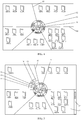
- a hard disk includes five sub-display areas, that is, C, D, E, F, and I, a spacing line 10 is displayed between adjacent sub-display areas 12, and spacing lines 10 of the five sub-display areas converge at a vertex 9, that is, the five sub-display areas share a same vertex 10.
- a display page is divided into several sub-display areas, and each sub-display area corresponds to one storage device partition and is used to independently display information of a corresponding partition, such as a name and a capacity, and a file, a folder, and the like in a partition root directory.
- a corresponding partition such as a name and a capacity, and a file, a folder, and the like in a partition root directory.
- space of the display page is fully used, user operations are simplified, and user operations among storage partitions are facilitated.
- an area of a sub-display area corresponding to the partition is divided according to a percentage of the storage capacity of the partition in the storage capacity of the storage device. Therefore, the storage capacity of each partition is clear at a glance, user operations are facilitated, and user experience is improved.
- the method further includes:
- a file, a subfolder, and a path of the folder that are included in the folder are displayed in the corresponding sub-display area.
- the user may input command information to enter the folder (for example, in a mobile phone, the user selects an icon of the folder and performs a corresponding opening operation on the display interface).
- a background program After receiving the command information, a background program queries a file directory in the corresponding partition according to the command information, acquires a file, a subfolder, and a path of the folder that are included in the folder, and performs a display in the corresponding sub-display area.
- the file such as an executable file, an image file, and an audio file
- the subfolder that are in the folder are displayed. In this case, sub-display area division on the display interface is unchanged.
- a file and a subfolder that are included in the layer directory and a path of the layer directory are displayed in the corresponding sub-display area.
- a path of the folder is displayed in a corresponding sub-display area.
- the user may choose to enter any layer directory in the displayed path of the folder.
- a file and a subfolder that are included in a layer directory that the user chooses to enter are displayed in the sub-display area, thereby improving convenience of user operations.
- the sub-display area corresponding to the partition may be displayed in a full screen manner on the display interface.
- the user may input corresponding command information, so that content in a sub-display area corresponding to the partition is displayed in a full screen manner on the display interface, that is, the display interface is no longer divided into sub-display areas but an entire sub-display area is used to display a file, a folder, and a path that are in the partition, thereby facilitating user viewing.
- the method further includes:
- the displaying the acquired attribute information of the storage partition in the sub-display area corresponding to the storage partition specifically includes: displaying the attribute information of the partition in a character manner, a visual graphical element manner, or a combination of a character manner and a visual graphical element manner.
- a visual graphical element may be a pattern with a specific style, where the specific style includes a color, a shape, a size, a fill, and the like of the pattern.
- a name of the storage partition and the partition storage capacity may be displayed in a character manner, and the used storage capacity and the available storage capacity may be displayed in a graphical manner.
- a first sector ring 11 is generated in the sub-display area by using the vertex 9 as the center of a circle, the spacing lines 10 between the adjacent sub-display areas 12 as start and end points, and a preset first radius length and a second radius length that is greater than the first radius length, where a total area of the first sector ring 11 represents a sum of the used storage capacity and the available storage capacity, and a visual element is filled in the first sector ring 11 that represents the used storage capacity or the available storage capacity, so as to distinguish the used storage capacity from the available storage capacity.
- a filled portion in the first sector ring 11 in the figure indicates the used storage capacity of the storage partition corresponding to the sub-display area
- an unfilled portion indicates the available storage capacity of the storage partition corresponding to the sub-display area.
- names (C, D, E, F, and I as shown in the figure) and total storage capacities (80 G, 120 G, 80 G, 80 G, and 40 G as shown in the figure) of the storage device partitions are displayed in a sector area enclosed by the first sector ring 11 and spacing lines 10 on its both sides respectively.
- the method further includes:
- a path index of a file fileW1 in a storage partition C is storage partition C - folder fileA - folder fileW - file fileW1
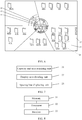
- its display method is: because the path index of the file fileW1 in the storage partition C is a two-level path index, another two sector rings need to be formed outside the first sector ring 11 and N is equal to four, generating a third arc boundary 13 in the sub-display area by using the vertex 9 as the center of a circle, the spacing lines 10 between the adjacent sub-display areas as start and end points, and a preset third radius length, and generating a fourth arc boundary 14 in the sub-display area by using a preset fourth radius length, where the fourth radius length is greater than the third radius length, the third radius length is greater than the second radius length, a second sector ring 15 is formed between the third arc boundary and the first sector ring, and a third sector ring 16 is formed between the fourth arc boundary and the second sector ring 15.
- the second sector ring 15 is used to present the first-level path folder fileA in the path index of the file fileW1
- the third sector ring 16 is used to present the second-level path folder fileW in the path index of the file fileW1.
- the method further includes:
- partition information of multiple storage devices may be displayed:
- backgrounds are displayed in the sub-display areas, and the backgrounds in the sub-display areas corresponding to the partitions of different storage devices are different.
- the electronic device is disposed with a storage device C and a storage device D.
- backgrounds in sub-display areas corresponding to all partitions of the storage device C are white, while backgrounds in sub-display areas of all partitions of the storage device D are black.
- the user can intuitively distinguish different storage devices and conveniently perform operations among different storage devices, and user experience is improved.
- the method for displaying storage information further includes: displaying, according to command information input by the user to enter the partition and in a full screen manner, the sub-display area corresponding to the partition on the display interface.
- the user may input corresponding command information, so that content in a sub-display area corresponding to the partition is displayed on the display interface in a full screen manner, that is, the display interface is no longer divided into sub-display areas but an entire sub-display area is used to display a file, a folder, and a path that are in the partition, thereby facilitating user viewing.
- a display page is divided into several sub-display areas, each sub-display area displays attribute information and storage information of a corresponding partition, and attribute information and path index information of a storage partition are displayed intuitively by using a character and a visual graphical element.
- a user may perform an operation in a sub-display area of a certain partition, and view storage information of a corresponding partition and a file and a folder that are stored in each level of storage directory.
- a sub-display area of each partition is displayed independently and does not affect each other. As a result, space of the display page is fully used, user operations are simplified, user operations among partitions are facilitated, and user experience is improved.
- An embodiment of the present invention provides a method for displaying a storage device partition.
- the method is applied to a computer, and the computer has a built-in hard disk and is connected to an external USB flash drive.
- the method includes:
- Attribute information of a partition corresponding to each sub-display area 12 and a file and folder 13 in the partition are displayed in each sub-display area 12, that is, a name, a capacity, available space, and used space of the partition C, D, E, F, or I are displayed in a sub-display area 12 corresponding to each partition.
- a display page is divided into five sector sub-display areas 12, and each sub-display area 12 corresponds to one partition.
- a capacity, available space, and used space of a partition are displayed by using a character and a visual graphical element, that is, a first sector ring 11 located at the sector center of the sub-display area 12 represents a total capacity of the partition, where a colored portion represents used space of a corresponding partition, and a uncolored portion represents available space of the corresponding partition.
- the name and the total capacity of the corresponding partition are marked in space enclosed by the first sector ring 11.
- a file and folder 20 in a root directory of the corresponding partition is displayed in the sub-display area 12.
- the partitions C, D, E, and F are the partitions of the hard disk, and the partition I is the partition of the USB flash drive. Therefore, the color of the colored portion in the first sector ring 11 of the partition C, D, E, or F is different from the color of the colored portion in the first sector ring 11 of the partition I for distinguishing, storage information of each partition is clear at a glance, and operations are facilitated.
- a scroll bar 17 is provided in the partition E and is used to adjust a display workspace in the sub-display area of the partition E, so that a user can conveniently view all files and folders in the partition E.
- command information input by the user to enter a folder in any partition that is, the user uses a mouse of the computer to click an icon of the folder, a file and a subfolder that are included in the folder and a path of the folder are displayed in a corresponding sub-display area.
- a folder filmW in a folder filmA in a root directory of the partition C a file and a subfolder (a folder filmW1 in the figure) that are in the folder W are displayed in the sub-display area of the partition C.
- a path of the folder W is displayed by using a sector ring outwards level by level outside the first sector ring 11 in the sector area, that is, the path folder filmA is displayed by using a second sector ring 15 and the path folder filmW is displayed by using a third sector ring 16.
- the user can click the second sector ring 15 in the sub-display area of the partition C by using the mouse if the user wants to enter the folder filmA in the path of the folder W. In this case, a file and a subfolder that are in the folder filmA are displayed in the sub-display area.
- a display page is divided into several sub-display areas, each sub-display area displays attribute information and storage information of a corresponding partition, and attribute information and path index information of a storage partition are displayed intuitively by using a character and a visual graphical element.
- a user may perform an operation in a sub-display area of a certain partition, and view storage information of a corresponding partition and a file and a folder that are stored in each level of storage directory.
- a sub-display area of each partition is displayed independently and does not affect each other. As a result, space of the display page is fully used, user operations are simplified, user operations among partitions are facilitated, and user experience is improved.
- An embodiment of the present invention further provides an apparatus for displaying a storage device partition. As shown in FIG. 7 , the apparatus includes:
- the apparatus further includes:
- the apparatus further includes:
- the attribute information displaying unit includes:
- the attribute information displaying unit includes:
- the second attribute information displaying module includes:
- the apparatus further includes:
- the apparatus further includes:
- a display page is divided into several sub-display areas, each sub-display area displays attribute information and storage information of a corresponding partition, and attribute information and path index information of a storage partition are displayed intuitively by using a character and a visual graphical element.
- a user may perform an operation in a sub-display area of a partition of a certain storage device, and view storage information of a corresponding partition and a file and a folder that are stored in each level of storage directory.
- a sub-display area of each partition is displayed independently and does not affect each other.
- An embodiment of the present invention further provides a terminal.
- the terminal includes a memory 31, a processor 32, and a monitor 33.
- the processor 32 is configured to: acquire a partition storage capacity of a storage partition and a total area of a display interface of a storage device, where the display interface is used to display the storage partition of the storage device and name information of the storage partition; determine a storage capacity percentage of the partition storage capacity in a total storage capacity of the storage device, and divide the display interface into different sub-display areas according to the determined storage capacity percentage and a total area of the display interface, where the different sub-display areas correspond to different storage partitions and are used to display name information of corresponding storage partitions, and a percentage of an area of a sub-display area in the total area of the display interface is the same as a storage capacity percentage of a partition storage capacity of a storage partition corresponding to the sub-display area in the total storage capacity of the storage device; and generate and display, on the display interface, a spacing line located between adjacent sub-display areas, where all sub-display areas share a same vertex.
- the processor 32 is further configured to acquire storage information stored in the storage partition; and display the acquired storage information in a sub-display area corresponding to the storage partition.
- the processor 32 is further configured to acquire attribute information of the storage partition, where the attribute information of the storage partition includes a storage capacity, a used storage capacity, and an available storage capacity of the partition; and display the acquired attribute information of the storage partition in the sub-display area corresponding to the storage partition.
- the displaying the acquired attribute information of the storage partition in the sub-display area corresponding to the storage partition specifically includes: displaying the attribute information of the partition in a character manner, a visual graphical element manner, or a combination of a character manner and a visual graphical element manner.
- the displaying the acquired attribute information of the storage partition in the sub-display area corresponding to the storage partition specifically includes: displaying a name of the storage partition and the partition storage capacity in a character manner, and displaying the used storage capacity and the available storage capacity in a graphical manner.
- the displaying the used storage capacity and the available storage capacity in a graphical manner specifically includes:
- the processor 32 is further configured to: generate an N th arc boundary in the sub-display area by using the vertex as the center of a circle, the spacing lines between the adjacent sub-display areas as start and end points, and a preset N th radius length, where N is greater than or equal to three, the N th radius length is greater than the second radius length or an (N-1) th radius length, so that an (N-1) th sector ring is formed between the N th arc boundary and the first sector ring or an (N-2) th sector ring, and the (N-1) th sector ring is used to present a path index of the storage information stored in the storage partition.
- the processor 32 is further configured to generate a scroll bar in at least one sub-display area, where the scroll bar is used to choose storage information displayed in the at least one sub-display area, the storage information is stored in a storage partition corresponding to the at least one sub-display area, and the storage information specifically is multiple folders.
- the memory 31 is configured to store the partition storage capacity of the storage partition and the total area of the display interface of the storage device, the storage capacity percentage of the partition storage capacity in the total storage capacity of the storage device, and the percentage of the area of the sub-display area in the total area of the display interface.
- the memory 31 is further configured to store the storage information in the storage partition and the attribute information of the storage partition.
- the monitor 33 is configured to display, on the display interface, sub-display areas corresponding to different storage partitions, where the percentage of the area of the sub-display area in the total area of the display interface is the same as a storage capacity percentage of a partition storage capacity of a storage partition corresponding to the sub-display area in the total storage capacity of the storage device, and display the spacing line located between the adjacent sub-display areas, where all sub-display areas share a same vertex.
- the monitor 33 is further configured to display the acquired storage information in the sub-display area corresponding to the storage partition, and display the acquired attribute information of the storage partition in the sub-display area corresponding to the storage partition.
- the monitor 33 is further configured to display the attribute information of the partition in a character manner, a visual graphical element manner, or a combination of a character manner and a visual graphical element manner.
- the monitor 33 is further configured to display a name of the storage partition and the partition storage capacity in a character manner, and display the used storage capacity and the available storage capacity in a graphical manner.
- the monitor 33 is further configured to display the first sector ring and the (N-1) th sector ring.
- the monitor 33 is further configured to display the scroll bar.
- a display page is divided into several sub-display areas, each sub-display area displays attribute information and storage information of a corresponding partition, and attribute information and path index information of a storage partition are displayed intuitively by using a character and a visual graphical element.
- a user may perform an operation in a sub-display area of a partition of a certain storage device, and view storage information of a corresponding partition and a file and a folder that are stored in each level of storage directory.
- a sub-display area of each partition is displayed independently and does not affect each other.
- the present invention may be implemented by software plus necessary universal hardware, and definitely, may also be implemented by hardware, but in many cases, the former one is a better implementation manner.
- the technical solutions of the present invention essentially, or the part contributing to the prior art may be embodied in a form of a software product.
- the computer software product is stored in a readable storage medium, for example, a floppy disk, a hard disk, or an optical disk of a computer, and includes several instructions for instructing a computer device (which may be a personal computer, a server, a network device, or the like) to perform the methods described in the embodiments of the present invention.
Landscapes
- Engineering & Computer Science (AREA)
- Theoretical Computer Science (AREA)
- General Engineering & Computer Science (AREA)
- Physics & Mathematics (AREA)
- General Physics & Mathematics (AREA)
- Human Computer Interaction (AREA)
- Data Mining & Analysis (AREA)
- Databases & Information Systems (AREA)
- Information Retrieval, Db Structures And Fs Structures Therefor (AREA)
- User Interface Of Digital Computer (AREA)
Claims (9)
- Verfahren zum Anzeigen von Speichervorrichtungspartitionen, das Folgendes umfasst:Erhalten einer Partitionsspeicherkapazität einer Speicherpartition und eines Gesamtbereichs einer Anzeigeschnittstelle einer Speichervorrichtung, wobei die Anzeigeschnittstelle verwendet wird, um die Speicherpartitionen der Speichervorrichtung anzuzeigen und um Nameninformationen der Speicherpartitionen anzuzeigen (S101);Bestimmen eines Speicherkapazitätsprozentsatzes der Partitionsspeicherkapazität in einer Gesamtspeicherkapazität der Speichervorrichtung und Unterteilen des Gesamtbereichs der Anzeigeschnittstelle in verschiedene Unteranzeigebereiche gemäß dem bestimmten Speicherkapazitätsprozentsatz und gemäß dem Gesamtbereich der Anzeigeschnittstelle, wobei die verschiedenen Unteranzeigebereiche verschiedenen Speicherpartitionen entsprechen und zum Anzeigen von Nameninformationen von entsprechenden Speicherpartitionen verwendet werden und wobei ein Prozentsatz eines Bereichs eines Unteranzeigebereichs in dem Gesamtbereich der Anzeigeschnittstelle gleich einem Speicherkapazitätsprozentsatz einer Partitionsspeicherkapazität einer Speicherpartition ist, die dem Unteranzeigebereich in der Gesamtspeicherkapazität der Speichervorrichtung entspricht (S102); undErzeugen und Anzeigen einer Zwischenraumlinie, die sich zwischen angrenzenden Unteranzeigebereichen befindet, auf der Anzeigeschnittstelle, wobei alle Unteranzeigebereiche einen selben Vertex teilen (S103);Erhalten von Attributinformationen der Speicherpartition, wobei die Attributinformationen der Speicherpartition eine Speicherkapazität, eine verwendete Speicherkapazität und eine verfügbare Speicherkapazität der Partition umfassen; undAnzeigen der erhaltenen Attributinformationen der Speicherpartition in dem Unteranzeigebereich, der der Speicherpartition entspricht;Erhalten von Speicherinformationen, die in der Speicherpartition gespeichert sind; undAnzeigen der erhaltenen Speicherinformationen in einem Unteranzeigebereich, der der Speicherpartition entspricht;Erzeugen einer Bildlaufleiste in wenigstens einem Unteranzeigebereich, wobei die Bildlaufleiste verwendet wird, um in dem wenigstens einen Unteranzeigebereich angezeigte Speicherinformationen auszuwählen, wobei die Speicherinformationen in einer Speicherpartition gespeichert sind, die dem wenigstens einen Unteranzeigebereich entspricht, und wobei die Speicherinformationen speziell mehrere Ordner sind.
- Verfahren nach Anspruch 1, wobei das Anzeigen der erhaltenen Attributinformationen der Speicherpartition in dem Unteranzeigebereich, der der Speicherpartition entspricht, speziell Folgendes umfasst: Anzeigen der Attributinformationen der Partition auf eine Schriftzeichenart, eine visuelle Grafikelementart oder eine Kombination einer Schriftzeichenart und einer visuellen Grafikelementart.
- Verfahren nach Anspruch 1, wobei das Anzeigen der erhaltenen Attributinformationen der Speicherpartition in dem Unteranzeigebereich, der der Speicherpartition entspricht, speziell Folgendes umfasst:Anzeigen eines Namens der Speicherpartition und der Partitionsspeicherkapazität auf eine Schriftzeichenart und Anzeigen der verwendeten Speicherkapazität und der verfügbaren Speicherkapazität auf eine grafische Art.
- Verfahren nach Anspruch 3, wobei das Anzeigen der verwendeten Speicherkapazität und der verfügbaren Speicherkapazität auf eine grafische Art speziell Folgendes umfasst:Erzeugen eines ersten Ringsektors in dem Unteranzeigebereich durch Verwenden des Vertex als den Mittelpunkt eines Kreises, der Zwischenraumlinien zwischen angrenzenden Unteranzeigebereichen als Start- und Endpunkte und einer vorgegebenen ersten Radiuslänge und einer zweiten Radiuslänge, die größer als die erste Radiuslänge ist, wobei ein Gesamtbereich des ersten Ringsektors eine Summe der verwendeten Speicherkapazität und der verfügbaren Speicherkapazität repräsentiert und wobei ein visuelles Element in dem ersten Ringsektor, welches die verwendete Speicherkapazität oder die verfügbare Speicherkapazität repräsentiert, gefüllt ist, so dass die verwendete Speicherkapazität von der verfügbaren Speicherkapazität unterschieden wird.
- Verfahren nach Anspruch 4, das ferner Folgendes umfasst:Erzeugen einer N-ten Bogengrenze in dem Unteranzeigebereich durch Verwenden des Vertex als den Mittelpunkt eines Kreises, der Zwischenraumlinien zwischen angrenzenden Unteranzeigebereichen als Start- und Endpunkte und einer vorgegebenen N-ten Radiuslänge, wobei N größer als oder gleich drei ist, wobei die N-te Radiuslänge größer als die zweite Radiuslänge oder eine (N-1)-te Radiuslänge ist, so dass ein (N-1)-ter Ringsektor zwischen der N-ten Bogengrenze und dem ersten Ringsektor oder einem (N-2)-ten Ringsektor gebildet wird, und wobei der (N-1)-te Ringsektor verwendet wird, um einen Pfadindex der Speicherinformationen, die in der Speicherpartition gespeichert sind, zu präsentieren.
- Einrichtung zum Anzeigen von Speichervorrichtungspartitionen, die Folgendes umfasst:eine Kapazität-und-Bereich-Erhalteeinheit (21), zum Erhalten einer Partitionsspeicherkapazität einer Speicherpartition und eines Gesamtbereichs einer Anzeigeschnittstelle einer Speichervorrichtung, wobei die Anzeigeschnittstelle verwendet wird, um die Speicherpartitionen der Speichervorrichtung anzuzeigen und um Nameninformationen der Speicherpartitionen anzuzeigen;eine Anzeigeunterteilungseinheit (22), die zum Bestimmen eines Speicherkapazitätsprozentsatzes der Partitionsspeicherkapazität in einer Gesamtspeicherkapazität der Speichervorrichtung und zum Unterteilen des Gesamtbereichs der Anzeigeschnittstelle in verschiedene Unteranzeigebereiche gemäß dem bestimmten Speicherkapazitätsprozentsatz und gemäß dem Gesamtbereich der Anzeigeschnittstelle konfiguriert ist, wobei die verschiedenen Unteranzeigebereiche verschiedenen Speicherpartitionen entsprechen undzum Anzeigen von Nameninformationen von entsprechenden Speicherpartitionen verwendet werden und wobei ein Prozentsatz eines Bereichs eines Unteranzeigebereichs in dem Gesamtbereich der Anzeigeschnittstelle gleich einem Speicherkapazitätsprozentsatz einer Partitionsspeicherkapazität einer Speicherpartition ist, die dem Unteranzeigebereich in der Gesamtspeicherkapazität der Speichervorrichtung entspricht; undeine Zwischenraumlinienanzeigeeinheit (23), die zum Erzeugen und Anzeigen einer Zwischenraumlinie, die sich zwischen angrenzenden Unteranzeigebereichen befindet, auf der Anzeigeschnittstelle konfiguriert ist, wobei alle Unteranzeigebereiche einen selben Vertex teilen;eine Attributinformationenerhalteeinheit, die zum Erhalten von Attributinformationen der Speicherpartition konfiguriert ist, wobei die Attributinformationen der Speicherpartition eine Speicherkapazität, eine verwendete Speicherkapazität und eine verfügbare Speicherkapazität der Partition umfassen; undeine Attributinformationenanzeigeeinheit, die zum Anzeigen der erhaltenen Attributinformationen der Speicherpartition in dem Unteranzeigebereich, der der Speicherpartition entspricht, konfiguriert ist;wobei die Attributinformationenanzeigeeinheit Folgendes umfasst:ein zweites Attributinformationenanzeigemodul, das zum Anzeigen eines Namens der Speicherpartition und der Partitionsspeicherkapazität auf eine Schriftzeichenart und zum Anzeigen der verwendeten Speicherkapazität und der verfügbaren Speicherkapazität auf eine grafische Art konfiguriert ist; undwobei das zweite Attributinformationenanzeigemodul Folgendes umfasst:ein Ringsektoranzeigemodul, das zum Erzeugen eines ersten Ringsektors in dem Unteranzeigebereich durch Verwenden des Vertex als den Mittelpunkt eines Kreises, der Zwischenraumlinien zwischen angrenzenden Speicherpartitionen als Start- und Endpunkte und einer vorgegebenen ersten Radiuslänge und einer zweiten Radiuslänge, die größer als die erste Radiuslänge ist, konfiguriert ist, wobei ein Gesamtbereich des ersten Ringsektors eine Summe der verwendeten Speicherkapazität und der verfügbaren Speicherkapazität repräsentiert und wobei ein visuelles Element in dem ersten Ringsektor, welches die verwendete Speicherkapazität oder die verfügbare Speicherkapazität repräsentiert, gefüllt ist, so dass die verwendete Speicherkapazität von der verfügbaren Speicherkapazität unterschieden wird.
- Einrichtung nach Anspruch 6, die ferner Folgendes umfasst:eine Speicherinformationenerhalteeinheit, die zum Erhalten von Speicherinformationen, die in der Speicherpartition gespeichert sind, konfiguriert ist; undeine Speicherinformationenanzeigeeinheit, die zum Anzeigen der erhaltenen Speicherinformationen in einem Unteranzeigebereich, der der Speicherpartition entspricht, konfiguriert ist.
- Einrichtung nach Anspruch 6, wobei die Attributinformationenanzeigeeinheit Folgendes umfasst:ein erstes Attributinformationenanzeigemodul, das zum Anzeigen der Attributinformationen der Partition auf eine Schriftzeichenart, eine visuelle Grafikelementart oder eine Kombination einer Schriftzeichenart und einer visuellen Grafikelementart konfiguriert ist.
- Einrichtung nach Anspruch 6, die ferner Folgendes umfasst:eine Pfadindexanzeigeeinheit, die zum Erzeugen einer N-ten Bogengrenze in dem Unteranzeigebereich durch Verwenden des Vertex als den Mittelpunkt eines Kreises, der Zwischenraumlinien zwischen angrenzenden Speicherpartitionen als Start- und Endpunkte und einer vorgegebenen N-ten Radiuslänge konfiguriert ist, wobei N größer als oder gleich drei ist, wobei die N-te Radiuslänge größer als die zweite Radiuslänge oder eine (N-1)-te Radiuslänge ist, so dass ein (N-1)-ter Ringsektor zwischen der N-ten Bogengrenze und dem ersten Ringsektor oder einem (N-2)-ten Ringsektor gebildet wird, und wobei der (N-1)-te Ringsektor verwendet wird, um einen Pfadindex der Speicherinformationen, die in der Speicherpartition gespeichert sind, zu präsentieren.
Applications Claiming Priority (2)
| Application Number | Priority Date | Filing Date | Title |
|---|---|---|---|
| CN201210301106.6A CN102902499B (zh) | 2012-08-22 | 2012-08-22 | 存储设备的分区显示方法和装置 |
| PCT/CN2013/074683 WO2014029218A1 (zh) | 2012-08-22 | 2013-04-25 | 存储设备的分区显示方法和装置 |
Publications (3)
| Publication Number | Publication Date |
|---|---|
| EP2801902A1 EP2801902A1 (de) | 2014-11-12 |
| EP2801902A4 EP2801902A4 (de) | 2015-02-25 |
| EP2801902B1 true EP2801902B1 (de) | 2017-12-06 |
Family
ID=47574749
Family Applications (1)
| Application Number | Title | Priority Date | Filing Date |
|---|---|---|---|
| EP13831368.9A Active EP2801902B1 (de) | 2012-08-22 | 2013-04-25 | Partitionsanzeigeverfahren und vorrichtung für eine speichervorrichtung |
Country Status (4)
| Country | Link |
|---|---|
| US (1) | US8769425B2 (de) |
| EP (1) | EP2801902B1 (de) |
| CN (1) | CN102902499B (de) |
| WO (1) | WO2014029218A1 (de) |
Families Citing this family (15)
| Publication number | Priority date | Publication date | Assignee | Title |
|---|---|---|---|---|
| CN102902499B (zh) * | 2012-08-22 | 2015-06-03 | 华为技术有限公司 | 存储设备的分区显示方法和装置 |
| CN104239023B (zh) * | 2013-06-24 | 2018-10-09 | 腾讯科技(深圳)有限公司 | 移动存储装置管理方法及装置 |
| CN105094557B (zh) * | 2015-07-27 | 2019-06-25 | 联想(北京)有限公司 | 一种显示控制方法及装置、电子设备 |
| CN105550252B (zh) * | 2015-12-09 | 2018-11-16 | 北京金山安全软件有限公司 | 一种文件定位方法、装置及电子设备 |
| CN105930252A (zh) * | 2016-04-29 | 2016-09-07 | 杨夫春 | 移动终端文件内存显示方法 |
| CN109426684B (zh) * | 2017-08-28 | 2020-04-03 | 维谛技术有限公司 | 一种封闭冷通道数据中心的3d模型绘制方法及装置 |
| KR20210024751A (ko) * | 2019-08-26 | 2021-03-08 | 에스케이하이닉스 주식회사 | 이종 메모리 장치를 포함하는 그래프 처리 시스템 및 그래프 처리 시스템의 동작방법 |
| JP7380027B2 (ja) | 2019-09-30 | 2023-11-15 | ブラザー工業株式会社 | 監視装置及び画像記録監視方法 |
| US20220398202A1 (en) * | 2019-11-05 | 2022-12-15 | Hui Lin | Structure and method for digital data memory card encryption |
| CN110888787A (zh) * | 2019-11-11 | 2020-03-17 | 第四范式(北京)技术有限公司 | 一种数据监测方法、装置及系统 |
| CN114741020B (zh) * | 2022-03-22 | 2025-05-30 | 深圳市鸿合创新信息技术有限责任公司 | 圆盘生成方法、装置、设备及介质 |
| US20240193099A1 (en) * | 2022-04-28 | 2024-06-13 | Hui Lin | Structure and method for digital data memory card encryption |
| US12388813B2 (en) | 2023-04-21 | 2025-08-12 | Bank Of America Corporation | Enhanced security with multiple factor authentication at devices using partitions |
| CN116974859A (zh) * | 2023-07-11 | 2023-10-31 | 武汉大学中南医院 | 存储信息的显示方法、计算机设备及存储介质 |
| CN120086099B (zh) * | 2025-05-07 | 2025-08-08 | 深圳市源微创新实业有限公司 | 一种移动固态硬盘 |
Family Cites Families (17)
| Publication number | Priority date | Publication date | Assignee | Title |
|---|---|---|---|---|
| US5581797A (en) * | 1993-10-22 | 1996-12-03 | Lucent Technologies Inc. | Method and apparatus for displaying hierarchical information of a large software system |
| US5652863A (en) * | 1995-06-07 | 1997-07-29 | International Business Machines Corporation | Graphical method of media partitioning on a hard disk |
| JP3398599B2 (ja) * | 1998-06-24 | 2003-04-21 | シャープ株式会社 | アプリケーションデータ処理装置 |
| US20030208322A1 (en) * | 2002-01-02 | 2003-11-06 | Aoki Kiyoko F. | Apparatus, method, and computer program product for plotting proteomic and genomic data |
| US7519910B2 (en) * | 2002-10-10 | 2009-04-14 | International Business Machines Corporation | Method for transferring files from one machine to another using adjacent desktop displays in a virtual network |
| JP4364706B2 (ja) * | 2004-04-05 | 2009-11-18 | 富士通株式会社 | 陰線処理方法 |
| US7594063B1 (en) * | 2004-08-27 | 2009-09-22 | Lexar Media, Inc. | Storage capacity status |
| KR100606078B1 (ko) * | 2005-05-17 | 2006-07-28 | 삼성전자주식회사 | 파일 위치정보 표시장치와 그에 따른 방법 |
| JP4781160B2 (ja) * | 2006-05-08 | 2011-09-28 | キヤノン株式会社 | 印刷システム |
| CN101291482A (zh) * | 2007-04-20 | 2008-10-22 | 乐金电子(中国)研究开发中心有限公司 | 一种移动通信终端及其存储器容量查看方法 |
| US7788297B2 (en) * | 2007-05-15 | 2010-08-31 | Microsoft Corporation | Interactive storage meter for a storage container |
| US8140787B2 (en) * | 2007-10-05 | 2012-03-20 | Imation Corp. | Methods for implementation of an active archive in an archiving system and managing the data in the active archive |
| US8245086B2 (en) * | 2009-06-26 | 2012-08-14 | International Business Machines Corporation | Visual feedback system for multiple partitions on a server |
| TWI382316B (zh) * | 2009-07-30 | 2013-01-11 | 張茂庭 | 具保全功能之隨身碟串接組合結構 |
| US8364021B2 (en) * | 2009-08-26 | 2013-01-29 | Echostar Technologies L.L.C. | Systems and methods for managing stored programs |
| JP5604894B2 (ja) * | 2010-02-16 | 2014-10-15 | セイコーエプソン株式会社 | 画像処理装置、画像処理方法、コンピュータープログラム |
| CN102902499B (zh) * | 2012-08-22 | 2015-06-03 | 华为技术有限公司 | 存储设备的分区显示方法和装置 |
-
2012
- 2012-08-22 CN CN201210301106.6A patent/CN102902499B/zh active Active
-
2013
- 2013-04-25 WO PCT/CN2013/074683 patent/WO2014029218A1/zh not_active Ceased
- 2013-04-25 EP EP13831368.9A patent/EP2801902B1/de active Active
- 2013-11-15 US US14/081,251 patent/US8769425B2/en active Active
Non-Patent Citations (2)
| Title |
|---|
| ANONYMOUS: "Coriolis Systems :: Products :: iPartition", 18 June 2012 (2012-06-18), XP055278890, Retrieved from the Internet <URL:https://web.archive.org/web/20120618121402/http://www.coriolis-systems.com/iPartition> [retrieved on 20160608] * |
| ANONYMOUS: "DiskSavvy - Disk Space Analyzer - DiskSavvy GUI Screenshots", 20 February 2012 (2012-02-20), XP055278877, Retrieved from the Internet <URL:https://web.archive.org/web/20120220094830/http://www.disksavvy.com/disksavvy_screenshots.html> [retrieved on 20160608] * |
Also Published As
| Publication number | Publication date |
|---|---|
| CN102902499B (zh) | 2015-06-03 |
| US20140075360A1 (en) | 2014-03-13 |
| CN102902499A (zh) | 2013-01-30 |
| EP2801902A4 (de) | 2015-02-25 |
| EP2801902A1 (de) | 2014-11-12 |
| WO2014029218A1 (zh) | 2014-02-27 |
| US8769425B2 (en) | 2014-07-01 |
Similar Documents
| Publication | Publication Date | Title |
|---|---|---|
| EP2801902B1 (de) | Partitionsanzeigeverfahren und vorrichtung für eine speichervorrichtung | |
| US11281843B2 (en) | Method of displaying axis of user-selectable elements over years, months, and days | |
| US20130067412A1 (en) | Grouping selectable tiles | |
| KR101320919B1 (ko) | 분할 화면을 통한 gui 제공방법 및 이를 적용한멀티미디어 기기 | |
| US8418257B2 (en) | Collection user interface | |
| JP7740814B2 (ja) | 展示方法、装置、及び、可読記憶媒体 | |
| US9910584B2 (en) | Method for manipulating folders and apparatus thereof | |
| JP2017021807A (ja) | ユーザ定義可能なプロパティを有するプレゼンテーションのセクション | |
| US20110271217A1 (en) | Configurable presets for tab groups | |
| US20130275919A1 (en) | Object visualization | |
| KR20130064458A (ko) | 복수 개의 영역으로 구분된 화면을 디스플레이하는 디스플레이 장치 및 그 방법 | |
| JP4701124B2 (ja) | 情報処理装置、情報処理方法 | |
| US20150046883A1 (en) | Method of displaying classified information and device of displaying classified information using the same | |
| US20170083212A1 (en) | Application program preview interface and operation method thereof | |
| US10768773B2 (en) | Dynamic text scroll control in a user interface | |
| EP3791250B1 (de) | Verfahren und elektronische vorrichtung zum auswählen von dateien in einem dateisystem | |
| KR101589969B1 (ko) | 네트워크형 파일 관리 방법 및 시스템 | |
| JP2008242880A (ja) | コンテンツ表示システム、コンテンツ表示方法および車載用の情報端末装置 | |
| EP4254151A1 (de) | Informationsverarbeitungssystem, -verfahren und -programm | |
| JP4674726B2 (ja) | ファイルの管理方法および情報処理装置 | |
| KR20170027031A (ko) | 데이터 파일명 관리장치 | |
| JP2009163653A (ja) | フォルダ格納装置 |
Legal Events
| Date | Code | Title | Description |
|---|---|---|---|
| PUAI | Public reference made under article 153(3) epc to a published international application that has entered the european phase |
Free format text: ORIGINAL CODE: 0009012 |
|
| 17P | Request for examination filed |
Effective date: 20140805 |
|
| AK | Designated contracting states |
Kind code of ref document: A1 Designated state(s): AL AT BE BG CH CY CZ DE DK EE ES FI FR GB GR HR HU IE IS IT LI LT LU LV MC MK MT NL NO PL PT RO RS SE SI SK SM TR |
|
| A4 | Supplementary search report drawn up and despatched |
Effective date: 20150122 |
|
| RIC1 | Information provided on ipc code assigned before grant |
Ipc: G06F 17/30 20060101ALI20150116BHEP Ipc: G06F 3/14 20060101AFI20150116BHEP |
|
| 17Q | First examination report despatched |
Effective date: 20150421 |
|
| DAX | Request for extension of the european patent (deleted) | ||
| STAA | Information on the status of an ep patent application or granted ep patent |
Free format text: STATUS: EXAMINATION IS IN PROGRESS |
|
| REG | Reference to a national code |
Ref country code: DE Ref legal event code: R079 Ref document number: 602013030563 Country of ref document: DE Free format text: PREVIOUS MAIN CLASS: G06F0003140000 Ipc: G06F0003060000 |
|
| RIC1 | Information provided on ipc code assigned before grant |
Ipc: G06F 17/30 20060101ALN20170228BHEP Ipc: G06F 3/06 20060101AFI20170228BHEP Ipc: G11B 27/32 20060101ALN20170228BHEP |
|
| RIC1 | Information provided on ipc code assigned before grant |
Ipc: G11B 27/32 20060101ALN20170322BHEP Ipc: G06F 3/06 20060101AFI20170322BHEP Ipc: G06F 17/30 20060101ALN20170322BHEP |
|
| RIC1 | Information provided on ipc code assigned before grant |
Ipc: G06F 17/30 20060101ALN20170329BHEP Ipc: G11B 27/32 20060101ALN20170329BHEP Ipc: G06F 3/06 20060101AFI20170329BHEP |
|
| GRAP | Despatch of communication of intention to grant a patent |
Free format text: ORIGINAL CODE: EPIDOSNIGR1 |
|
| STAA | Information on the status of an ep patent application or granted ep patent |
Free format text: STATUS: GRANT OF PATENT IS INTENDED |
|
| INTG | Intention to grant announced |
Effective date: 20170620 |
|
| GRAS | Grant fee paid |
Free format text: ORIGINAL CODE: EPIDOSNIGR3 |
|
| GRAA | (expected) grant |
Free format text: ORIGINAL CODE: 0009210 |
|
| STAA | Information on the status of an ep patent application or granted ep patent |
Free format text: STATUS: THE PATENT HAS BEEN GRANTED |
|
| AK | Designated contracting states |
Kind code of ref document: B1 Designated state(s): AL AT BE BG CH CY CZ DE DK EE ES FI FR GB GR HR HU IE IS IT LI LT LU LV MC MK MT NL NO PL PT RO RS SE SI SK SM TR |
|
| REG | Reference to a national code |
Ref country code: GB Ref legal event code: FG4D |
|
| REG | Reference to a national code |
Ref country code: AT Ref legal event code: REF Ref document number: 952962 Country of ref document: AT Kind code of ref document: T Effective date: 20171215 Ref country code: CH Ref legal event code: EP |
|
| REG | Reference to a national code |
Ref country code: IE Ref legal event code: FG4D |
|
| REG | Reference to a national code |
Ref country code: DE Ref legal event code: R096 Ref document number: 602013030563 Country of ref document: DE |
|
| REG | Reference to a national code |
Ref country code: FR Ref legal event code: PLFP Year of fee payment: 6 |
|
| REG | Reference to a national code |
Ref country code: NL Ref legal event code: MP Effective date: 20171206 |
|
| REG | Reference to a national code |
Ref country code: LT Ref legal event code: MG4D |
|
| PG25 | Lapsed in a contracting state [announced via postgrant information from national office to epo] |
Ref country code: LT Free format text: LAPSE BECAUSE OF FAILURE TO SUBMIT A TRANSLATION OF THE DESCRIPTION OR TO PAY THE FEE WITHIN THE PRESCRIBED TIME-LIMIT Effective date: 20171206 Ref country code: NO Free format text: LAPSE BECAUSE OF FAILURE TO SUBMIT A TRANSLATION OF THE DESCRIPTION OR TO PAY THE FEE WITHIN THE PRESCRIBED TIME-LIMIT Effective date: 20180306 Ref country code: SE Free format text: LAPSE BECAUSE OF FAILURE TO SUBMIT A TRANSLATION OF THE DESCRIPTION OR TO PAY THE FEE WITHIN THE PRESCRIBED TIME-LIMIT Effective date: 20171206 Ref country code: FI Free format text: LAPSE BECAUSE OF FAILURE TO SUBMIT A TRANSLATION OF THE DESCRIPTION OR TO PAY THE FEE WITHIN THE PRESCRIBED TIME-LIMIT Effective date: 20171206 Ref country code: ES Free format text: LAPSE BECAUSE OF FAILURE TO SUBMIT A TRANSLATION OF THE DESCRIPTION OR TO PAY THE FEE WITHIN THE PRESCRIBED TIME-LIMIT Effective date: 20171206 |
|
| REG | Reference to a national code |
Ref country code: AT Ref legal event code: MK05 Ref document number: 952962 Country of ref document: AT Kind code of ref document: T Effective date: 20171206 |
|
| PG25 | Lapsed in a contracting state [announced via postgrant information from national office to epo] |
Ref country code: RS Free format text: LAPSE BECAUSE OF FAILURE TO SUBMIT A TRANSLATION OF THE DESCRIPTION OR TO PAY THE FEE WITHIN THE PRESCRIBED TIME-LIMIT Effective date: 20171206 Ref country code: BG Free format text: LAPSE BECAUSE OF FAILURE TO SUBMIT A TRANSLATION OF THE DESCRIPTION OR TO PAY THE FEE WITHIN THE PRESCRIBED TIME-LIMIT Effective date: 20180306 Ref country code: HR Free format text: LAPSE BECAUSE OF FAILURE TO SUBMIT A TRANSLATION OF THE DESCRIPTION OR TO PAY THE FEE WITHIN THE PRESCRIBED TIME-LIMIT Effective date: 20171206 Ref country code: LV Free format text: LAPSE BECAUSE OF FAILURE TO SUBMIT A TRANSLATION OF THE DESCRIPTION OR TO PAY THE FEE WITHIN THE PRESCRIBED TIME-LIMIT Effective date: 20171206 Ref country code: GR Free format text: LAPSE BECAUSE OF FAILURE TO SUBMIT A TRANSLATION OF THE DESCRIPTION OR TO PAY THE FEE WITHIN THE PRESCRIBED TIME-LIMIT Effective date: 20180307 |
|
| PG25 | Lapsed in a contracting state [announced via postgrant information from national office to epo] |
Ref country code: NL Free format text: LAPSE BECAUSE OF FAILURE TO SUBMIT A TRANSLATION OF THE DESCRIPTION OR TO PAY THE FEE WITHIN THE PRESCRIBED TIME-LIMIT Effective date: 20171206 |
|
| PG25 | Lapsed in a contracting state [announced via postgrant information from national office to epo] |
Ref country code: EE Free format text: LAPSE BECAUSE OF FAILURE TO SUBMIT A TRANSLATION OF THE DESCRIPTION OR TO PAY THE FEE WITHIN THE PRESCRIBED TIME-LIMIT Effective date: 20171206 Ref country code: CZ Free format text: LAPSE BECAUSE OF FAILURE TO SUBMIT A TRANSLATION OF THE DESCRIPTION OR TO PAY THE FEE WITHIN THE PRESCRIBED TIME-LIMIT Effective date: 20171206 Ref country code: SK Free format text: LAPSE BECAUSE OF FAILURE TO SUBMIT A TRANSLATION OF THE DESCRIPTION OR TO PAY THE FEE WITHIN THE PRESCRIBED TIME-LIMIT Effective date: 20171206 |
|
| PG25 | Lapsed in a contracting state [announced via postgrant information from national office to epo] |
Ref country code: AT Free format text: LAPSE BECAUSE OF FAILURE TO SUBMIT A TRANSLATION OF THE DESCRIPTION OR TO PAY THE FEE WITHIN THE PRESCRIBED TIME-LIMIT Effective date: 20171206 Ref country code: SM Free format text: LAPSE BECAUSE OF FAILURE TO SUBMIT A TRANSLATION OF THE DESCRIPTION OR TO PAY THE FEE WITHIN THE PRESCRIBED TIME-LIMIT Effective date: 20171206 Ref country code: IT Free format text: LAPSE BECAUSE OF FAILURE TO SUBMIT A TRANSLATION OF THE DESCRIPTION OR TO PAY THE FEE WITHIN THE PRESCRIBED TIME-LIMIT Effective date: 20171206 Ref country code: RO Free format text: LAPSE BECAUSE OF FAILURE TO SUBMIT A TRANSLATION OF THE DESCRIPTION OR TO PAY THE FEE WITHIN THE PRESCRIBED TIME-LIMIT Effective date: 20171206 Ref country code: PL Free format text: LAPSE BECAUSE OF FAILURE TO SUBMIT A TRANSLATION OF THE DESCRIPTION OR TO PAY THE FEE WITHIN THE PRESCRIBED TIME-LIMIT Effective date: 20171206 |
|
| REG | Reference to a national code |
Ref country code: DE Ref legal event code: R097 Ref document number: 602013030563 Country of ref document: DE |
|
| PLBE | No opposition filed within time limit |
Free format text: ORIGINAL CODE: 0009261 |
|
| STAA | Information on the status of an ep patent application or granted ep patent |
Free format text: STATUS: NO OPPOSITION FILED WITHIN TIME LIMIT |
|
| 26N | No opposition filed |
Effective date: 20180907 |
|
| PG25 | Lapsed in a contracting state [announced via postgrant information from national office to epo] |
Ref country code: DK Free format text: LAPSE BECAUSE OF FAILURE TO SUBMIT A TRANSLATION OF THE DESCRIPTION OR TO PAY THE FEE WITHIN THE PRESCRIBED TIME-LIMIT Effective date: 20171206 Ref country code: MC Free format text: LAPSE BECAUSE OF FAILURE TO SUBMIT A TRANSLATION OF THE DESCRIPTION OR TO PAY THE FEE WITHIN THE PRESCRIBED TIME-LIMIT Effective date: 20171206 Ref country code: SI Free format text: LAPSE BECAUSE OF FAILURE TO SUBMIT A TRANSLATION OF THE DESCRIPTION OR TO PAY THE FEE WITHIN THE PRESCRIBED TIME-LIMIT Effective date: 20171206 |
|
| REG | Reference to a national code |
Ref country code: CH Ref legal event code: PL |
|
| REG | Reference to a national code |
Ref country code: BE Ref legal event code: MM Effective date: 20180430 |
|
| REG | Reference to a national code |
Ref country code: IE Ref legal event code: MM4A |
|
| PG25 | Lapsed in a contracting state [announced via postgrant information from national office to epo] |
Ref country code: LU Free format text: LAPSE BECAUSE OF NON-PAYMENT OF DUE FEES Effective date: 20180425 |
|
| PG25 | Lapsed in a contracting state [announced via postgrant information from national office to epo] |
Ref country code: BE Free format text: LAPSE BECAUSE OF NON-PAYMENT OF DUE FEES Effective date: 20180430 Ref country code: LI Free format text: LAPSE BECAUSE OF NON-PAYMENT OF DUE FEES Effective date: 20180430 Ref country code: CH Free format text: LAPSE BECAUSE OF NON-PAYMENT OF DUE FEES Effective date: 20180430 |
|
| PG25 | Lapsed in a contracting state [announced via postgrant information from national office to epo] |
Ref country code: IE Free format text: LAPSE BECAUSE OF NON-PAYMENT OF DUE FEES Effective date: 20180425 |
|
| PG25 | Lapsed in a contracting state [announced via postgrant information from national office to epo] |
Ref country code: MT Free format text: LAPSE BECAUSE OF NON-PAYMENT OF DUE FEES Effective date: 20180425 |
|
| PG25 | Lapsed in a contracting state [announced via postgrant information from national office to epo] |
Ref country code: TR Free format text: LAPSE BECAUSE OF FAILURE TO SUBMIT A TRANSLATION OF THE DESCRIPTION OR TO PAY THE FEE WITHIN THE PRESCRIBED TIME-LIMIT Effective date: 20171206 |
|
| PG25 | Lapsed in a contracting state [announced via postgrant information from national office to epo] |
Ref country code: HU Free format text: LAPSE BECAUSE OF FAILURE TO SUBMIT A TRANSLATION OF THE DESCRIPTION OR TO PAY THE FEE WITHIN THE PRESCRIBED TIME-LIMIT; INVALID AB INITIO Effective date: 20130425 Ref country code: PT Free format text: LAPSE BECAUSE OF FAILURE TO SUBMIT A TRANSLATION OF THE DESCRIPTION OR TO PAY THE FEE WITHIN THE PRESCRIBED TIME-LIMIT Effective date: 20171206 |
|
| PG25 | Lapsed in a contracting state [announced via postgrant information from national office to epo] |
Ref country code: MK Free format text: LAPSE BECAUSE OF NON-PAYMENT OF DUE FEES Effective date: 20171206 Ref country code: CY Free format text: LAPSE BECAUSE OF FAILURE TO SUBMIT A TRANSLATION OF THE DESCRIPTION OR TO PAY THE FEE WITHIN THE PRESCRIBED TIME-LIMIT Effective date: 20171206 |
|
| PG25 | Lapsed in a contracting state [announced via postgrant information from national office to epo] |
Ref country code: AL Free format text: LAPSE BECAUSE OF FAILURE TO SUBMIT A TRANSLATION OF THE DESCRIPTION OR TO PAY THE FEE WITHIN THE PRESCRIBED TIME-LIMIT Effective date: 20171206 Ref country code: IS Free format text: LAPSE BECAUSE OF FAILURE TO SUBMIT A TRANSLATION OF THE DESCRIPTION OR TO PAY THE FEE WITHIN THE PRESCRIBED TIME-LIMIT Effective date: 20180406 |
|
| PGFP | Annual fee paid to national office [announced via postgrant information from national office to epo] |
Ref country code: DE Payment date: 20250305 Year of fee payment: 13 |
|
| PGFP | Annual fee paid to national office [announced via postgrant information from national office to epo] |
Ref country code: GB Payment date: 20260312 Year of fee payment: 14 |
|
| PGFP | Annual fee paid to national office [announced via postgrant information from national office to epo] |
Ref country code: FR Payment date: 20260309 Year of fee payment: 14 |