EP2802131B1 - Tragbares Gerät mit Modul zum Erweitern der Funktionsweise - Google Patents
Tragbares Gerät mit Modul zum Erweitern der Funktionsweise Download PDFInfo
- Publication number
- EP2802131B1 EP2802131B1 EP14179815.7A EP14179815A EP2802131B1 EP 2802131 B1 EP2802131 B1 EP 2802131B1 EP 14179815 A EP14179815 A EP 14179815A EP 2802131 B1 EP2802131 B1 EP 2802131B1
- Authority
- EP
- European Patent Office
- Prior art keywords
- magnet
- main body
- expansion module
- mobile device
- expansion
- Prior art date
- Legal status (The legal status is an assumption and is not a legal conclusion. Google has not performed a legal analysis and makes no representation as to the accuracy of the status listed.)
- Not-in-force
Links
Images


Classifications
-
- G—PHYSICS
- G06—COMPUTING OR CALCULATING; COUNTING
- G06F—ELECTRIC DIGITAL DATA PROCESSING
- G06F1/00—Details not covered by groups G06F3/00 - G06F13/00 and G06F21/00
- G06F1/16—Constructional details or arrangements
- G06F1/1613—Constructional details or arrangements for portable computers
-
- G—PHYSICS
- G06—COMPUTING OR CALCULATING; COUNTING
- G06F—ELECTRIC DIGITAL DATA PROCESSING
- G06F1/00—Details not covered by groups G06F3/00 - G06F13/00 and G06F21/00
- G06F1/16—Constructional details or arrangements
- G06F1/1613—Constructional details or arrangements for portable computers
- G06F1/1632—External expansion units, e.g. docking stations
-
- G—PHYSICS
- G06—COMPUTING OR CALCULATING; COUNTING
- G06F—ELECTRIC DIGITAL DATA PROCESSING
- G06F1/00—Details not covered by groups G06F3/00 - G06F13/00 and G06F21/00
- G06F1/16—Constructional details or arrangements
- G06F1/1613—Constructional details or arrangements for portable computers
- G06F1/1633—Constructional details or arrangements of portable computers not specific to the type of enclosures covered by groups G06F1/1615 - G06F1/1626
- G06F1/1637—Details related to the display arrangement, including those related to the mounting of the display in the housing
- G06F1/1654—Details related to the display arrangement, including those related to the mounting of the display in the housing the display being detachable, e.g. for remote use
-
- G—PHYSICS
- G06—COMPUTING OR CALCULATING; COUNTING
- G06F—ELECTRIC DIGITAL DATA PROCESSING
- G06F1/00—Details not covered by groups G06F3/00 - G06F13/00 and G06F21/00
- G06F1/16—Constructional details or arrangements
- G06F1/1613—Constructional details or arrangements for portable computers
- G06F1/1633—Constructional details or arrangements of portable computers not specific to the type of enclosures covered by groups G06F1/1615 - G06F1/1626
- G06F1/1675—Miscellaneous details related to the relative movement between the different enclosures or enclosure parts
- G06F1/1679—Miscellaneous details related to the relative movement between the different enclosures or enclosure parts for locking or maintaining the movable parts of the enclosure in a fixed position, e.g. latching mechanism at the edge of the display in a laptop or for the screen protective cover of a PDA
-
- H—ELECTRICITY
- H04—ELECTRIC COMMUNICATION TECHNIQUE
- H04M—TELEPHONIC COMMUNICATION
- H04M1/00—Substation equipment, e.g. for use by subscribers
- H04M1/02—Constructional features of telephone sets
- H04M1/0202—Portable telephone sets, e.g. cordless phones, mobile phones or bar type handsets
- H04M1/0254—Portable telephone sets, e.g. cordless phones, mobile phones or bar type handsets comprising one or a plurality of mechanically detachable modules
-
- H—ELECTRICITY
- H04—ELECTRIC COMMUNICATION TECHNIQUE
- H04M—TELEPHONIC COMMUNICATION
- H04M1/00—Substation equipment, e.g. for use by subscribers
- H04M1/72—Mobile telephones; Cordless telephones, i.e. devices for establishing wireless links to base stations without route selection
- H04M1/724—User interfaces specially adapted for cordless or mobile telephones
- H04M1/72448—User interfaces specially adapted for cordless or mobile telephones with means for adapting the functionality of the device according to specific conditions
- H04M1/7246—User interfaces specially adapted for cordless or mobile telephones with means for adapting the functionality of the device according to specific conditions by connection of exchangeable housing parts
Definitions
- the present invention relates to an expansion module, and more particularly to a module for expanding a function of a mobile device and a mobile device having the same.
- Mobile devices include electronic devices which are portable and have at least one of voice and telephone call functions, information input and/or output functions, a data storage function and the like.
- the mobile device can further capture still images or moving images, play music or video files, play games, receive broadcast and the like, so as to be implemented as an integrated multimedia player.
- US 2009/257203 A1 relates to a mobile communication device with replaceable function modules includes a main body and an externally connected device.
- the main body serves as a central member, and has a main hybrid joint including an electrical contact and a magnetic joint.
- the main hybrid joint of the main body is joined to a device hybrid joint of the externally connected device, so as to realize the function thereof.
- the main body activates a functional module of the externally connected device functional module.
- the main body and the externally connected device are further joined through the magnetic joints. Therefore, when separated by accidentally falling onto the ground, the mobile communication device can be rejoined through the magnetic joints, and thus it is unnecessary to worry about the unavailability due to the break-down of the joint portion.
- EP 1 791 050 A2 relates to an auto-aligning and connecting structure used to connect and align an electronic device and an accessory, wherein a plurality of first magnetic bodies are disposed on a first surface of the electrical device and a plurality of second magnetic bodies are disposed on a second surface of the accessory.
- the magnetic pole of the first magnetic bodies and the second magnetic bodies are appropriately arranged so the first magnetic bodies and the second magnetic bodies can attract each other when the first surface and the second surface approach each other. Then, the electronic device and the accessories are connected to each other when the first surface and the second surface connect.
- US 2004/190239 A1 relates to a detachable keyboard structure including a first magnetic component, a second magnetic component, and a movable component.
- the first magnetic component is disposed in the wireless keyboard while the second magnetic component is disposed in the computer main body.
- the first and the second magnetic components produce magnetization due to the opposite magnetisms thereof for attracting the keyboard to the computer main body.
- the moveable component is capable of transferring the magnetic relation between the first magnetic component and the second magnetic component. When the moveable component is forced to move and therefore transfer the magnetic relation, the first and the second magnetic components produce repellence with each other due to the same magnetism thereof for detaching the keyboard from the computer main body.
- US 2008/232061 A1 relates to a portable electronic system including a body and a dock.
- the body has a waterproof first connector and a first attracting portion, wherein the first connector has a plurality of electrical terminals.
- the dock has a second connector and a second attracting portion, wherein the second connector has a plurality of retractable pogo pins.
- the present invention is directed to a module for expanding a function of a mobile device and a mobile device having the same that substantially obviates one or more problems due to limitations and disadvantages of the related art.
- An object of the present invention is to provide an expansion module, capable of expanding the function of a mobile device, and a mobile device having the same.
- Another object of the present invention is to provide a mechanism for facilitating coupling and separation between an expansion module and a mobile device main body.
- the module for expanding a function of a mobile device and a mobile device having the same includes a main body having a coupling element mounted thereon, and an expansion module electrically connected to the main body, wherein the expansion module comprises a magnet disposed to apply a magnetic force to the coupling element to couple the expansion module with the main body, and a movement converter configured to move the magnet away from the coupling element so as to decrease the magnetic force between the coupling element and the magnet thereby decoupling the main body from the expansion module.
- the expansion module for a mobile device includes an expansion body detachably coupled to one surface of the mobile device, a magnet disposed at the expansion body to apply a magnetic force to a coupling element in the mobile device thereby coupling the expansion body with the mobile device, and a movement converter configured to move the magnet away from the coupling element so as to decrease the magnetic force between the coupling element and the magnet thereby decoupling the mobile device from the expansion body.
- the expansion module for a mobile device includes a first coupling element configured to be coupled to a second coupling element disposed at the mobile device, and a manipulation member configured to decouple the first coupling element and the second coupling element by converting a linear motion of the manipulation member to a rotary motion of the second coupling element.
- module and “unit or portion” for components used herein in description are merely provided for facilitation of preparing this specification, and thus they are not granted a specific meaning or function. Hence, it should be noticed that “module” and “unit or portion” can be used together.
- Mobile devices described in the present invention may include laptop computers, tablet PCs, smart phones, digital broadcasting terminals, personal digital assistants (PDAs), portable multimedia players (PMPs), navigators, and the like.
- PDAs personal digital assistants
- PMPs portable multimedia players
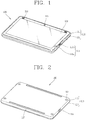
- FIG. 1 is a perspective view of a mobile device 100 in accordance with an exemplary embodiment according to the present invention, which shows a tablet PC as one example of a mobile device.
- the disclosed mobile device 100 includes one body (or main body) 110.
- the mobile device 100 may be applicable to various structures, such as mobile devices having at least two bodies coupled to each other to be relatively movable.
- a body may include a case (housing, casing, cover, etc.) forming the outside of the mobile device 100.
- the case is formed by a front case 111 and a rear case 112.
- various electronic components may be disposed in a space between the front case 111 and the rear case 112.
- At least one intermediate case may additionally be disposed between the front case 111 and the rear case 112.
- the cases can be formed of resin by injection molding, or formed using metallic materials, such as stainless steel (STS) or titanium (Ti).
- a display unit 113, an audio output module 114, a camera 115, a user input unit 116 and the like may be disposed on the body, in particular, on the front case 111.
- the display unit 113 may occupy most of a principal surface of the front case 111.
- the display unit 113 may be configured to display visible information or image information.
- the display unit 113 may include at least one of a Liquid Crystal Display (LCD), a Thin Film Transistor-LCD (TFT-LCD), an Organic Light Emitting Diode (OLED) display, a flexible display, or a three-dimensional (3D) display.
- the display unit 113 may include a touchpad for allowing a user's touch input. In this case, the display unit 113 may operate as a touch screen.
- the display unit 113 may output various types of visual information. Such information may be output in various forms of letter, number, symbol, graphic, icon or the like. For input of such information, at least one of the letters, the numbers, the symbols, the graphics or the icons may be displayed in a present arrangement, thereby implementing a type of keypad, which may be called as "soft key.”
- the display unit may operate as an overall region, or by being divided into plural regions. For the latter, the plurality of regions may be configured to cooperatively operate together.
- the user input unit 116 may be manipulated to receive commands for controlling operations of the mobile device 100, and include a plurality of manipulation units 116a and 116b.
- the manipulation units 116a and 116b may also be referred to as a manipulating portion, which can be manipulated in any tactile manner that user can make a touch input.
- the manipulation units 116a and 116b can be implemented as a keypad, a dome switch, a touchpad (e.g., static pressure/capacitance), a jog wheel, a jog switch and the like.
- the information input via the plurality of manipulation units 116a and 116b may be set in various manners.
- the first manipulation unit 116a may be used for input of commands, such as START, END, etc.
- the second manipulation unit 116b may be used for reception of commands, such as SCROLL or the like, or commands, such as volume adjustment of sounds output from the audio output module 114.
- the audio output module 114 and the camera 115 may be located at a region adjacent to one of both ends of the display unit 113.
- the audio output module 114 may include a speaker, a receiver, and the like.
- the camera 115 may be installed in an electronic device body to be rotatable or popped up.
- a controller for controlling the display unit 113 and the user input unit 116 may be disposed in the body.
- the controller may be implemented as a printed circuit board.
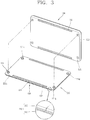
- FIG. 2 is a rear perspective view of the mobile device 100 of FIG. 1 .
- An audio output module may further be disposed at a rear surface of the mobile device body.
- the audio output module may cooperate with the audio output module 114 (see FIG. 1 ) to provide stereo output.
- the audio output module may be configured to operate as a speakerphone.
- a wireless communication or broadcast signal reception antenna may be disposed at a side surface of the mobile device body.
- the antenna may be retractable into the mobile device body.
- the mobile device body may include a microphone 117, an interface 118, and the like.
- the microphone 117 may be disposed at a region adjacent to a different end portion from one end portion having the audio output module 114.
- the interface 118 and the like may be located at side surfaces of the front case 111 and the rear case 112.
- the interface 118 may be at least one of a connection terminal for wired or wireless connection to an earphone, a port for a short-range communication (e.g., infrared (IrDA) port, Bluetooth port, wireless LAN port, etc.), or power supply terminals for power supply to the mobile device.
- the interface 118 may also be a card socket for accommodating an external card such as Subscriber Identification Module (SIM), User Identity Module (UIM), memory card for storing information or the like.
- SIM Subscriber Identification Module
- UIM User Identity Module
- a power supply unit (not shown) for supplying power to the mobile device 100 may be mounted to the mobile device body.
- the power supply unit may be a built-in battery, so as to be mounted inside the body.
- a coupling element 121 may be externally exposed from one surface of the rear case 112.
- the coupling element 121 may allow one member disposed in the body or the front case 111 to be coupled to the rear case 112.
- the coupling element 121 may be configured as a bolt, pin or the like.
- the one member may be a printed circuit board, an injected structure or the like.
- the coupling element 121 may be made of a magnetic material so as to be attracted to a magnetic force of a magnet.
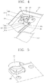
- FIG. 3 is an assembled view showing that an expansion module 200 is mounted to the mobile device 100 of FIG. 1 .
- the expansion module 200 may detachably be coupled to the mobile device 100.
- the expansion module 200 may be an external battery for power supply to the mobile device 100, which is exemplarily shown in FIG. 3 .
- the expansion module 200 may be electrically connected to the mobile device 100 to supply power to electronic components of the mobile device 100.
- the expansion module 200 may be configured to charge an internal battery of the mobile device 100.
- Guide recesses 122 may be formed at the rear case 112 of the mobile device 100, and guide protrusions 202 matching the shape of the guide recesses 122 may be formed at a principal surface of the expansion module 200. Accordingly, the position where the expansion module 200 is attached to the mobile terminal 100 can be decided.
- the expansion module 200 may include an expansion body 210, a magnet 221 and a movement converter 230.
- the expansion body 210 may be detachably coupled to one surface of the main body 110 of the mobile device 100.
- the expansion body 210 may be realized to be chargeable from the exterior and supply power to the mobile device 100.
- the rear case 112 overlaps with one surface of the expansion module 200, i.e., with the principal surface of the expansion body 210.
- the expansion body 210 may form an installation space for electronic components by its front and rear cases 211 and 212.
- the front case 211 is coupled to the rear case 122 of the mobile device 100 by the coupling element 121.
- a plurality of coupling elements 121 may be provided near the corners of the rear case 122.
- the magnets 221 may be present at the expansion body 210, and disposed in correspondence with the coupling elements 121 to apply a magnetic force to the coupling elements 121 when the expansion body 210 is coupled to the main body 110 of the mobile device 100. Consequently, the expansion module 200 is fixed due to the magnetic force upon being coupled to the mobile device 100. Also, metallic substances, separate from the coupling elements 121, may be disposed at the positions corresponding to the magnets 221.
- the expansion module 200 may include a mesh structure (not shown) thereby forming a Faraday cage in regions where shielding of magnetic field is desirable.
- the rear case 212 may have a mesh structure thereon to prevent magnetic field from leaking out through the rear case 212, thereby preventing interference between the expansion module and other electronic devices near the expansion module.
- the movement converter 230 may be configured to move the magnet 221 in a direction opposite to the coupling element 121 (i.e., in a direction moving away from the coupling element 121) by manipulation for reduction of the magnetic force. Accordingly, a user would not be able to easily detach the expansion module 200, which is fixed by a strong magnetic force from the magnets 221, from the mobile device 100.
- the movement converter 230 can enable the user to easily detach the expansion module 200 by spacing the magnets 221 apart from the coupling element 121, thereby reducing the magnetic force.
- a plurality of magnets 221 may be provided to correspond to the plurality of coupling elements 121, and part of the plurality of magnets 221 may be associated with the movement converter 230. For example, only some of magnets 221a and 221b adjacent to one side of the front case 211 may be moved by the movement converter 230, while the other magnets 221c and 221d adjacent to another side are fixed to the front case 211.
- FIG. 4 is a partially exploded view of the expansion module 200 of FIG. 3
- FIG. 5 is an enlarged view of a profile member of FIG. 4
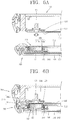
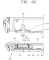
- FIGS. 6A to 6C are partial sectional views showing coupling and separation between the mobile device 100 and the expansion module 200 of FIG. 3
- FIG. 7 is a planar view showing the movement converter 230 of FIG. 3 .
- sliding guiding units 240 which allow sliding of the magnets 221, may be provided at the expansion module 200.
- Each sliding guiding unit 240 may include a magnet case 241 and a hollow body 242.
- the magnet case 241 may include first and second cases 241a and 241b, which form installation space for the magnet 221.
- the hollow body 242 may be mounted to the expansion body 210, and configured such that the magnet case 241 is slid toward or away from the coupling element 121 along an inner circumference.
- the magnet case 241 is inserted into the hollow body 242 to be guided along an inner circumferential surface of the hollow body 242, thereby being slid in an axial direction of the hollow body 242.
- the hollow body 242 is mounted to the front case 211 of the expansion module 200 as a separate component.
- the hollow body 242 may be integrally formed with the front case 211 of the expansion module 200.
- the sliding guiding unit 240 may include an elastic member 243.
- the elastic member 243 may support at least part of the magnet case 241 so as to apply an elastic force to the magnet case 241 in a direction opposite to the coupling element 121.
- the elastic member 243 may include a coil spring.
- the coil spring is disposed to cover an outer circumference of the magnet case 241.
- One end of the coil spring supports part of the hollow body 242 and another end supports an end portion of the magnet case 241.
- FIG. 6A shows a detached state between the mobile device 100 and the expansion module 200.
- the elastic member 243 applies the elastic force to the magnet case 241 toward the inside of the expansion body 210. Accordingly, the magnet case 241 can be disposed without protruding from the hollow body 242 or the front case 211.
- FIG. 6B shows a coupled state between the mobile device 100 and the expansion module 200.
- the magnet 221 is slid toward the coupling element 121 by the magnetic force between the magnet 221 and the coupling element 121 so that the magnet case 241 and the coupling element 121 come in contact with each other. Accordingly, the expansion module 200 can be fixed to the rear case 112 of the mobile device 100.
- An insertion hole 123 for inserting the coupling element 121 therein may be formed at the rear case 112.
- the insertion hole 123 may have a stepped portion in an insertion direction. Accordingly, a reception portion 124 for receiving a head of the coupling element 121 therein is formed in the insertion hole 123.
- FIG. 6B at least one of the magnet 221 and the magnet case 241 is partially inserted into the insertion hole 123 when the expansion module 200 is coupled to the mobile device 100.
- FIG. 6B exemplarily shows that the magnet case 241 is partially inserted into the insertion hole 123.
- at least part of the magnet 221 may be inserted into the insertion hole 123.
- the movement converter 230 may include a manipulation member 231, a rotation generator 250, and a sliding generator 260.
- the manipulation member 231 may be disposed at one surface of the expansion body 210, and configured to be slidable along a side surface of the expansion body 210 in response to a user's manipulation.
- the rotation generator 250 may rotate the magnet 221 upon manipulation of the manipulation member 231.
- the rotation generator 250 may include a rotation plate 251 and a connection bar 252.
- the rotation plate 251 may be configured such that at least part of its outer circumference is connected to the manipulation member 231, thereby being rotated responsive to sliding of the manipulation member 231.
- a protrusion 251a is protruded from the outer circumference of the rotation plate 251 and inserted into a manipulation groove 231a of the manipulation member 231.
- an inner surface of the manipulation groove 231a presses the protrusion 251a.
- a rotational force is applied to the rotation plate 251.
- connection bar 252 may be configured such that one end thereof is connected to the rotation plate 251 and another end is connected to the magnet case 241 having the magnet 221 therein, thereby transferring the rotational force to the magnet 221.
- the connection bar 252 is connected to a portion adjacent to the outer circumference of the rotation plate 251.
- the magnet case 241 is pulled or pushed due to the connection bar 252.
- a connection protrusion 241c is protruded from an outer surface of the magnet case 241 in a radial direction of the magnet 221. The connection protrusion 241c is then connected to the connection bar 252.
- connection protrusion 241c is formed at the first case 241a and a groove in which the connection protrusion 241c is inserted is formed at the second case 241b.
- connection bar 252 pulls or pushes the protrusion 241c
- the magnet case 241 is responsively rotated about an axis of the magnet 221 along an inner circumference of a hollow portion of the hollow body 242.
- the sliding generator 260 rotates the magnet 221 and also move the magnet 221 in an axial direction of the rotation as the magnet 221 rotates.
- the sliding generator 260 may include a protrusion 261 and a profile member 262.
- the protrusion 261 may be protruded from an outer circumference of the magnet case 241, and provided in plurality.
- the plurality of protrusions 261a, 261b and 261c may be aligned on an outer circumference of the first case 241a, together with the connection protrusion 241c, with preset intervals.
- the second case 241b may have grooves in which the protrusions 261a, 261b and 261c are inserted.
- the protrusion 261 may be placed at the profile member 262.
- the profile member 262 may be formed to be slanted along the outer circumference of the magnet case 241 such that the magnet case 241 can be slid along in an axial direction of the rotation of the magnet 221, in response to the rotation of the protrusion 261.
- the profile member 262 may be formed at a surface adjacent to an opening of the hollow body 242.
- the profile member 262 may be formed integrally with the hollow body 242, in a stepped form in a direction that the hollow body 242 is penetrated.
- the profile member 262 may be formed to be gradually shorter or longer in height in the direction that the hollow body 242 is penetrated. Accordingly, the rotary motion of the protrusion 261 changes into a sliding motion of the magnet case 241.
- the movement of the connection bar 252 makes the magnet case 241 rotate. Accordingly, the magnet case 241 moves away from the coupling element 121.
- the elastic member 243 applies an elastic force to the magnet case 241 to help move the magnet 221.
- the movement of the magnet case 241 results in attenuation of the magnetic force between the coupling element 121 and the magnet 221, which helps the user to easily separate the expansion module 200 from the mobile device 100.
- FIGS. 8A to 8C are a sectional view and enlarged views of a mobile device in accordance with another exemplary embodiment according to the present invention.
- the similar components as those in the previous embodiment will be understood by the foregoing description.
- a connection region 370 may be formed at one surface of a mobile device main body 310, and an expansion connection region 470 may be formed at an expansion body 410 of an expansion module so as to be electrically connected to the connection region 370 when the expansion body 410 is coupled to the mobile device main body 310.
- the connection region 370 is formed in an annular shape and a coupling element 321 is disposed inside the connection region 370.
- the connection region 370 may be less exposed by being configured to cover an outer circumference of the coupling element 321.
- the coupling element 321 may be provided in plurality.
- the connection region 370 may be configured to cover one of the plurality of coupling elements 321.
- an insertion hole 323 for inserting the coupling element 321 may be formed at a rear case, and the connection region 370 may define an opening of the insertion hole 323.
- the expansion connection region 470 may be configured to cover a magnet 421.
- the magnet 421 may be provided in plurality.
- the expansion connection region 470 may be configured to cover one of the plurality of magnets 421 so as to match the connection region 370.
- Interfaces for exchange of data and/or power between the main body 310 and the expansion body 410 may be disposed at the connection region 370 and the expansion connection region 470, respectively.
- the interfaces may include connection terminals 371 and 471.
- end portions of the connection terminals 371 and 471 are protruded from the connection region 370 and the expansion connection region 470, respectively, so as to elastically press each other.
- the connection terminals 371 of the connection region 370 may act as pogo pins
- the connection terminals 471 of the expansion connection region 470 may act as C-clips.
- a protrusion 444 may be formed at one surface of the magnet case 441.
- a groove 321a corresponding to the protrusion 444 may be disposed at the coupling element 321.
- the protrusion 444 is protruded from an externally exposed surface of the magnet case 441.
- the protrusion 444 is inserted into the groove 321a when the magnet case 441 is slid by the magnetic force between the coupling element 321 and the magnet 421.
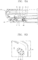
- FIGS. 9A and 9B are enlarged views of a mobile device in accordance with another exemplary embodiment of the present invention.
- a connection unit 580 may be formed at a rear case 512 of a mobile device, and include connection terminals 581 and a shielding portion 582.
- connection terminals 581 may be protruded from one surface of the main body 510 to be electrically connected to an expansion body (not shown).
- the shielding portion 582 may be formed to cover the connection terminals 581.
- the shielding portion 582 may be configured to be pushable between a position exposing side portions of the connection terminals 581 and a position shielding the side portions of the connection terminals 581.
- the shielding portion 582 may be elastically pushable.
- connection unit 580 is spaced apart from the coupling element.
- the connection unit 580 may also be formed at the connection region 370 (see FIG. 8A ).
- the connection terminals may be exposed when the shielding portion is moved by the expansion connection region 470 (see FIG. 8B ) in a pressing manner, thereby achieving an electric connection to the connection terminals of the expansion connection region 470.
- FIG. 10 is an assembled view of a mobile device in accordance with another exemplary embodiment according to the present invention.
- An expansion module 800 may include a holder 810 and an input device 820.
- the holder 810 may be coupled to a mobile device 700.
- the holder 810 may include magnets, sliding guiding units, and a movement converter which have been described in the previous embodiment.
- the input device 820 may be aligned to intersect the holder 810 and allow input of a control command to the mobile device 700.
- a manipulation member 831 may be present at one side surface, e.g., a horizontal side surface of the holder 810.
- the electric connection between the mobile device 700 and the expansion module 800 may be formed by interfaces for data exchange. This configuration may allow power supply to the mobile device 700 via the interfaces.
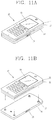
- FIGS. 11A and 11B are a perspective view and an assembled view of a mobile terminal in accordance with another embodiment according to the present invention.
- a mobile device may include mobile terminals having a wireless communication function.
- a mobile terminal 10 according to the present invention may not be limited to a bar type as shown herein, but it may be applicable to various types, such as a slide type, a folder type, a swing type and the like.
- the mobile terminal 10 may include a display unit 13 on a front case 11 thereof and a detachable battery 14 on a rear case 12 thereof.
- the detachable battery 14 may be the expansion module described in the previous embodiments.
- Coupling elements may be mounted at the rear case 12. Magnets 15 may be slidably attached onto the battery 14. Upon attaching the magnets 15 onto the coupling elements, the battery 14 is coupled to the rear case 12. A manipulation member 16 may be present at one side of the battery 14. The magnets may be moved away from the coupling elements by the sliding guiding units and the movement converter, which have been described in the previous embodiment, in response to the manipulation of the manipulation member 16. The battery 14 may accordingly be detached from the rear case 12.
- the sliding of the magnets can realize a detachable mechanism which facilitates the coupling and separation between the main body of the mobile device and the expansion module.
- the present invention can realize an electric connection between the expansion module and the mobile device by use of adjacent regions of the coupling elements, thereby implementing a connection mechanism which is less externally exposed.
- the expansion module and the mobile device may both have coupling elements.
- the first coupling element disposed at the expansion module can be configured to be coupled to a second coupling element disposed at the mobile device.
- the first coupling element may be a magnet while the second coupling element is a metallic substance as shown in FIGs. 6A-6B and FIG. 8A .
- the first coupling element and the second coupling elements can both be a first magnet and a second magnet, respectively.
- the first and second magnets can be configured such that the first magnet attracts the second magnet in a first state while the first magnet repels the second magnet in a second state.
- the second state can be a state wherein the second magnet is rotated by 180 degrees from the first state.
- the first magnet can have N/S polarity while the second magnet has S/N polarity in the first state so that the first magnet attracts the second magnet when the second magnet is placed on the first magnet.
- the manipulation member disposed at the expansion module can be configured to decouple the first coupling element and the second coupling element by converting a linear motion of the manipulation member to a rotary motion of the second coupling element, thereby rendering the first state into the second state.
- the first coupling element can be configured to mechanically (rather than by magnetic force) latch the second coupling element in a coupled state.
- the manipulation member disposed at the expansion module can be configured to decouple the first coupling element and the second coupling element by converting a linear motion of the manipulation member to a rotary motion of the second coupling element.
Landscapes
- Engineering & Computer Science (AREA)
- Theoretical Computer Science (AREA)
- Computer Hardware Design (AREA)
- Human Computer Interaction (AREA)
- Physics & Mathematics (AREA)
- General Physics & Mathematics (AREA)
- General Engineering & Computer Science (AREA)
- Signal Processing (AREA)
- Computer Networks & Wireless Communication (AREA)
- Telephone Set Structure (AREA)
- Casings For Electric Apparatus (AREA)
- Details Of Connecting Devices For Male And Female Coupling (AREA)
- Dynamo-Electric Clutches, Dynamo-Electric Brakes (AREA)
Claims (5)
- Mobile Vorrichtung, die Folgendes umfasst:einen Hauptkörper (100, 310, 700, 10) mit mindestens einem auf ihm angebrachten magnetischen Element; undein Erweiterungsmodul (200, 800), das mit dem Hauptkörper (100, 310, 700, 10) elektrisch verbunden ist,wobei das Erweiterungsmodul (200, 800) umfasst:einen Halter (810), der konfiguriert ist, an den Hauptkörper (100, 310, 700, 10) gekoppelt zu sein;einen Magneten (421), der an dem Halter (810) angebracht ist und ausgelegt ist, eine magnetische Kraft auf das mindestens eine magnetische Element auszuüben, um das Erweiterungsmodul (200, 800) mit dem Hauptkörper (100, 310, 700, 10) zu koppeln; undeine Eingabevorrichtung (820), die konfiguriert ist, die Eingabe eines Steuerbefehls in den Hauptkörper (100, 310, 700, 10) zu erlauben, wenn der Hauptkörper (100, 310, 700, 10) an den Halter (810) des Erweiterungsmoduls (200, 800) gekoppelt ist,wobei ein Verbindungsbereich (370) an dem Hauptkörper (100, 310, 700, 10) gebildet ist,wobei ein Erweiterungsverbindungsbereich (470) an dem Erweiterungsmodul (810) gebildet ist und mit dem Verbindungsbereich (470) elektrisch verbunden ist, wenn der Hauptkörper (100, 310, 700, 10) an das Erweiterungsmodul (200, 800) gekoppelt ist,mindestens einen Vorsprung (444), der an einer außen freiliegenden Fläche des Erweiterungsmoduls (200, 800) angeordnet ist;wobei der Hauptkörper (100, 310, 700, 10) mindestens eine Nut (321a) enthält, die in den mindestens einen Vorsprung eingefügt ist, wenn der Hauptkörper (100, 310, 700, 10) an den Halter (810) des Erweiterungsmoduls (200, 800) gekoppelt ist,dadurch gekennzeichnet, dassVerbindungsanschlüsse (371) des Hauptkörpers und Verbindungsanschlüsse (471) des Erweiterungsmoduls (200, 800) jeweils an dem Verbindungsbereich (370) und dem Erweiterungsverbindungsbereich (470) vorgesehen sind undwobei die Verbindungsanschlüsse (371, 471) des Hauptkörpers (100, 310, 700, 10) und des Erweiterungsmoduls (200, 800) von dem Verbindungsbereich (370) und dem Erweiterungsverbindungsbereich (470) jeweils vorstehen und elastisch gegeneinander drücken, wenn das Erweiterungsmodul (200, 800) an den Hauptkörper (100, 310, 700, 10) gekoppelt ist,wobei ein Bewegungsumsetzer (230, 830) in dem Halter (810) enthalten ist und konfiguriert ist, den Magneten von dem mindestens einen magnetischen Element wegzubewegen,wobei der Bewegungsumsetzer (230, 830) enthält:ein Bedienungselement (231), das an einer Seite des Erweiterungsmoduls angeordnet ist;einen Rotationsgenerator (250), der konfiguriert ist, den Magneten zu drehen, wenn das Bedienungselement betätigt wird; undeinen Gleitgenerator (260), der konfiguriert ist, den Magneten entlang einer axialen Richtung des Magneten zu schieben, wenn sich der Magnet dreht,wobei der Gleitgenerator enthält:einen Vorsprung (261), der von einem äußeren Umfang eines Magnetgehäuses, das den Magneten enthält, vorsteht; undein Profilelement (262), an dem der Vorsprung positioniert ist, wobei das Profilelement entlang des äußeren Umfangs des Magnetgehäuses derart abgeschrägt ist, dass das Magnetgehäuse in die axiale Richtung geschoben wird, wenn sich der Vorsprung dreht.
- Vorrichtung nach Anspruch 1, wobei die Eingabevorrichtung (820) mit einer Seite des Halters (810) verbunden ist.
- Vorrichtung nach Anspruch 1 oder 2, wobei die Eingabevorrichtung (820) konfiguriert ist, so ausgerichtet zu sein, dass sie den Halter (810) überkreuzt.
- Vorrichtung nach einem der Ansprüche 1 bis 3, wobei der Hauptkörper (100, 310, 700, 10) enthält:einen einzigen Körper eines Stangentyps; undeine Anzeigeeinheit (113), die an dem einzigen Körper angebracht ist und konfiguriert ist, als ein Berührungsbildschirm zu arbeiten.
- Vorrichtung nach Anspruch 1, wobei der Rotationsgenerator (250) enthält:eine Rotationsplatte (251), deren äußerer Umfang mit dem Bedienungselement verbunden ist, um gedreht zu werden; undeine Verbindungsstange (252), deren eines Ende mit der Rotationsplatte verbunden ist und deren anderes Ende mit einem Magnetgehäuse, das den Magneten enthält, verbunden ist.
Applications Claiming Priority (2)
| Application Number | Priority Date | Filing Date | Title |
|---|---|---|---|
| KR1020100020122A KR101084651B1 (ko) | 2010-03-05 | 2010-03-05 | 확장 모듈 및 이를 구비한 휴대 전자기기 |
| EP10008538.0A EP2364005B1 (de) | 2010-03-05 | 2010-08-16 | Tragbares Gerät mit Modul zum Erweitern der Funktionsweise |
Related Parent Applications (2)
| Application Number | Title | Priority Date | Filing Date |
|---|---|---|---|
| EP10008538.0A Division-Into EP2364005B1 (de) | 2010-03-05 | 2010-08-16 | Tragbares Gerät mit Modul zum Erweitern der Funktionsweise |
| EP10008538.0A Division EP2364005B1 (de) | 2010-03-05 | 2010-08-16 | Tragbares Gerät mit Modul zum Erweitern der Funktionsweise |
Publications (3)
| Publication Number | Publication Date |
|---|---|
| EP2802131A2 EP2802131A2 (de) | 2014-11-12 |
| EP2802131A3 EP2802131A3 (de) | 2015-01-07 |
| EP2802131B1 true EP2802131B1 (de) | 2018-11-28 |
Family
ID=44168850
Family Applications (2)
| Application Number | Title | Priority Date | Filing Date |
|---|---|---|---|
| EP14179815.7A Not-in-force EP2802131B1 (de) | 2010-03-05 | 2010-08-16 | Tragbares Gerät mit Modul zum Erweitern der Funktionsweise |
| EP10008538.0A Not-in-force EP2364005B1 (de) | 2010-03-05 | 2010-08-16 | Tragbares Gerät mit Modul zum Erweitern der Funktionsweise |
Family Applications After (1)
| Application Number | Title | Priority Date | Filing Date |
|---|---|---|---|
| EP10008538.0A Not-in-force EP2364005B1 (de) | 2010-03-05 | 2010-08-16 | Tragbares Gerät mit Modul zum Erweitern der Funktionsweise |
Country Status (7)
| Country | Link |
|---|---|
| US (1) | US8300389B2 (de) |
| EP (2) | EP2802131B1 (de) |
| JP (1) | JP5694734B2 (de) |
| KR (1) | KR101084651B1 (de) |
| CN (1) | CN102196690B (de) |
| DE (1) | DE202010018203U1 (de) |
| TW (1) | TWI454124B (de) |
Families Citing this family (76)
| Publication number | Priority date | Publication date | Assignee | Title |
|---|---|---|---|---|
| US8606340B2 (en) | 2010-11-22 | 2013-12-10 | Blackberry Limited | Multi-display mobile device |
| US8503174B2 (en) * | 2011-02-04 | 2013-08-06 | Research In Motion Limited | Magnetic slider mechanism for electronic devices and methods of use |
| USD701862S1 (en) * | 2011-02-18 | 2014-04-01 | Lg Electronics Inc. | Cart barcode scanner |
| KR101945948B1 (ko) | 2011-12-30 | 2019-02-12 | 삼성전자주식회사 | 디스플레이 장치 |
| US10019034B2 (en) | 2012-03-14 | 2018-07-10 | Popsockets Llc | Docking connector platform for mobile electronic devices |
| US11892875B2 (en) | 2012-03-14 | 2024-02-06 | Popsockets Llc | Magnetic docking platform and detachable docking accessories |
| US20130335925A1 (en) * | 2012-06-13 | 2013-12-19 | Acer Incorporated | Portable electronic device |
| EP2893595B1 (de) * | 2012-09-03 | 2019-10-23 | I-Blades, Inc. | Verfahren und system für intelligente kontaktarrays und stapelvorrichtungen |
| TWI557987B (zh) * | 2012-09-17 | 2016-11-11 | 宏碁股份有限公司 | 行動裝置 |
| CN103682583B (zh) * | 2012-09-21 | 2016-12-21 | 宏碁股份有限公司 | 移动装置 |
| US9332329B2 (en) | 2012-09-28 | 2016-05-03 | Htc Corporation | Electronic apparatus |
| WO2014051616A1 (en) * | 2012-09-28 | 2014-04-03 | Hewlett-Packard Development Company, L.P. | Electronic device including retractable bolt member |
| US9137918B2 (en) * | 2012-09-28 | 2015-09-15 | Htc Corporation | Electronic apparatus and method for assembling the same |
| US9282668B2 (en) | 2012-09-28 | 2016-03-08 | Htc Corporation | Electronic apparatus and method for assembling the same |
| TW201429360A (zh) * | 2013-01-09 | 2014-07-16 | Giga Byte Tech Co Ltd | 筆記型電腦之上蓋體 |
| CN104035484B (zh) * | 2013-03-04 | 2018-03-27 | 联想(北京)有限公司 | 一种电子设备 |
| US20140252779A1 (en) * | 2013-03-11 | 2014-09-11 | Nokia Corporation | Locking Arrangement |
| TWI565394B (zh) * | 2013-03-20 | 2017-01-01 | 緯創資通股份有限公司 | 具鎖扣腳墊的電子裝置、其鎖扣腳墊結構、及堆疊式電子裝置系統 |
| TWI535362B (zh) * | 2013-05-02 | 2016-05-21 | 仁寶電腦工業股份有限公司 | 連接組件及具有此連接組件的電子裝置 |
| TWI510891B (zh) * | 2013-05-03 | 2015-12-01 | Wistron Corp | 可攜式電子設備 |
| TWI491340B (zh) * | 2013-05-20 | 2015-07-01 | Supermax Co Ltd | Positioning device for electronic devices |
| CN203481851U (zh) * | 2013-07-03 | 2014-03-12 | 力新创展电子(香港)有限公司 | 一种备用电池产品及其堆叠充电系统 |
| TWI482575B (zh) * | 2013-07-11 | 2015-04-21 | Wistron Corp | 電子系統及其連接機構 |
| US9372507B2 (en) * | 2013-09-28 | 2016-06-21 | Intel Corporation | Adjustable support and a mobile computing device having an adjustable support |
| US9690332B2 (en) | 2013-10-09 | 2017-06-27 | Kabushiki Kaisha Toshiba | Electronic device, combining device, and detaching method |
| TWI498714B (zh) * | 2013-11-28 | 2015-09-01 | Wistron Corp | 可攜式電子模組 |
| KR102272337B1 (ko) * | 2014-02-21 | 2021-07-05 | 삼성전자주식회사 | 전자 장치 및 커버가 결합된 전자 장치 |
| CN114637375B (zh) | 2014-03-28 | 2025-01-28 | 英特尔公司 | 计算设备中磁力的调节 |
| US9500208B2 (en) | 2014-04-25 | 2016-11-22 | Apple Inc. | Magnetic preloading of joints |
| KR102166378B1 (ko) * | 2014-05-16 | 2020-10-15 | 삼성전자주식회사 | 분리 가능한 전자 장치 |
| KR20150133053A (ko) * | 2014-05-19 | 2015-11-27 | 엘지전자 주식회사 | 와치 타입의 이동 단말기 및 이를 구비하는 이동 단말 시스템 |
| US10133314B2 (en) | 2014-05-26 | 2018-11-20 | Apple Inc. | Portable computing system |
| US10228721B2 (en) | 2014-05-26 | 2019-03-12 | Apple Inc. | Portable computing system |
| CN207586791U (zh) | 2014-09-30 | 2018-07-06 | 苹果公司 | 便携式计算系统 |
| US9575514B2 (en) * | 2015-01-09 | 2017-02-21 | Apple Inc. | Enclosure features of a portable computing device |
| CN204087716U (zh) * | 2014-10-28 | 2015-01-07 | 北京京东方多媒体科技有限公司 | 一种显示装置 |
| US10003218B2 (en) * | 2014-12-20 | 2018-06-19 | Intel Corporation | Chassis design for wireless-charging coil integration for computing systems |
| US20160179140A1 (en) * | 2014-12-20 | 2016-06-23 | Intel Corporation | Chassis Design for Wireless-Charging Coil Integration for Computing Systems |
| US9955570B2 (en) | 2015-01-09 | 2018-04-24 | Apple Inc. | Features of a flexible connector in a portable computing device |
| US10162390B2 (en) | 2015-01-16 | 2018-12-25 | Apple Inc. | Hybrid acoustic EMI foam for use in a personal computer |
| TWI577253B (zh) * | 2015-05-08 | 2017-04-01 | 宏碁股份有限公司 | 電子裝置 |
| KR102270484B1 (ko) | 2015-06-24 | 2021-06-29 | 삼성전자주식회사 | 디스플레이 모듈, 디스플레이 장치 및 디스플레이 모듈의 조립 또는 해체 방법 |
| TWI548973B (zh) * | 2015-07-13 | 2016-09-11 | 宏碁股份有限公司 | 擴充裝置 |
| US20170064054A1 (en) * | 2015-08-24 | 2017-03-02 | Motorola Mobility Llc | Modular Device Docking with Camera Protrusion Alignment |
| US10728752B2 (en) | 2015-10-13 | 2020-07-28 | Confivox Inc. | Case for a portable device |
| JP2019507996A (ja) * | 2015-12-14 | 2019-03-22 | レッド.コム,エルエルシー | モジュール式デジタルカメラおよび携帯電話 |
| FR3053139B1 (fr) * | 2016-06-23 | 2018-06-29 | Groupe Adeo | Facade de protection interchangeable pour terminal d'affichage |
| KR102009663B1 (ko) * | 2016-07-26 | 2019-10-21 | 삼성전자주식회사 | 디스플레이 장치의 결합 구조 및 디스플레이 장치 |
| TWI608330B (zh) * | 2016-12-23 | 2017-12-11 | 華碩電腦股份有限公司 | 可攜式電子裝置 |
| EP3565647A1 (de) * | 2017-01-05 | 2019-11-13 | Bensussen Deutsch & Associates, LLC | Steuergeräte mit beweglichen aktuatoren |
| WO2019066507A1 (ko) * | 2017-09-28 | 2019-04-04 | 주식회사 초위스컴퍼니 | 피부 진단 장치 및 이를 위한 커플링 시스템 |
| DE102018106257A1 (de) * | 2017-11-29 | 2019-05-29 | Riedel Communications International GmbH | Sprechstelle für ein Intercom-Netzwerk |
| KR102486270B1 (ko) * | 2018-03-14 | 2023-01-10 | 삼성전자주식회사 | 디스플레이 장치 |
| US10852773B2 (en) * | 2018-07-31 | 2020-12-01 | Dell Products, L.P. | Multi-form factor information handling system (IHS) with an accessory backpack |
| CN112514357B (zh) * | 2018-09-06 | 2023-06-20 | Oppo广东移动通信有限公司 | 移动终端及其主机端 |
| CN109802457A (zh) * | 2019-01-18 | 2019-05-24 | 青岛海信移动通信技术股份有限公司 | 一种电子设备及其充电方法 |
| CN110336901B (zh) * | 2019-06-28 | 2021-04-27 | 维沃移动通信有限公司 | 移动终端及外接设备 |
| US11654873B1 (en) * | 2019-11-07 | 2023-05-23 | AGA Tools & Products, Inc. | Park release apparatus and method of use |
| CN111314523B (zh) | 2020-03-23 | 2021-05-14 | 维沃移动通信有限公司 | 电子设备及其功能模块 |
| CN114338966B (zh) * | 2020-09-30 | 2026-04-07 | 华为技术有限公司 | 一种电子设备和扩展组件 |
| US11320876B1 (en) | 2020-12-07 | 2022-05-03 | Dell Products L.P. | Information handling system handle with integrated thermal rejection system |
| US11733742B2 (en) | 2020-12-07 | 2023-08-22 | Dell Products L.P. | Information handling system integrated speaker with variable volume sound chamber |
| US11262820B1 (en) | 2020-12-07 | 2022-03-01 | Dell Products L.P. | Information handling system dynamic thermal behavior |
| US11262821B1 (en) | 2020-12-07 | 2022-03-01 | Dell Products L.P. | Information handling system with articulated cooling fins between interleaved and separated positions |
| US11262822B1 (en) | 2020-12-07 | 2022-03-01 | Dell Products L.P. | Information handling system dynamic cooling fan articulation to manage thermal parameters |
| US11262807B1 (en) | 2020-12-11 | 2022-03-01 | Dell Products L.P. | Information handling system speaker mount under a transparent housing cover |
| US11893163B2 (en) | 2020-12-11 | 2024-02-06 | Dell Products L.P. | Information handling system virtual and physical keyboard position coordination |
| US12038795B2 (en) | 2020-12-11 | 2024-07-16 | Dell Products L.P. | Information handling system visual presentation with audio vector based information |
| US11662712B2 (en) | 2020-12-11 | 2023-05-30 | Dell Products L.P. | Information handling system housing cover inflatable seal |
| CN116917834A (zh) | 2021-02-26 | 2023-10-20 | 松下知识产权经营株式会社 | 电子设备 |
| KR102764421B1 (ko) * | 2021-11-23 | 2025-02-07 | 주식회사 케이티앤지 | 에어로졸 발생 장치 |
| CN114183447A (zh) * | 2021-11-29 | 2022-03-15 | 骑记(深圳)科技有限公司 | 吸合牢固的磁吸扣 |
| DE102021134403A1 (de) * | 2021-12-22 | 2023-06-22 | Systec & Solutions Gmbh | Magnetisch gehaltertes nutzerschnittstellengerät und set hierfür |
| EP4468278A4 (de) * | 2022-07-20 | 2025-06-11 | Samsung Electronics Co., Ltd | Anzeigevorrichtung |
| TWI856649B (zh) * | 2023-05-10 | 2024-09-21 | 神基科技股份有限公司 | 電子裝置 |
| US20250316822A1 (en) * | 2024-04-03 | 2025-10-09 | Core SWX, LLC | Device, system, and method for parallel charging stacked cinematography battery packs |
Family Cites Families (24)
| Publication number | Priority date | Publication date | Assignee | Title |
|---|---|---|---|---|
| US6109528A (en) * | 1995-12-22 | 2000-08-29 | Intermec Ip Corp. | Ergonomic hand-held data terminal and data collection system |
| US6137686A (en) * | 1998-04-10 | 2000-10-24 | Casio Computer Co., Ltd. | Interchangeable modular arrangement of computer and accessory devices |
| US6510048B2 (en) * | 2001-01-04 | 2003-01-21 | Apple Computer, Inc. | Keyboard arrangement |
| US6785127B1 (en) * | 2001-10-19 | 2004-08-31 | Logitech Europe S.A. | Handheld computer attachment apparatus |
| JP3092874U (ja) * | 2002-09-19 | 2003-04-04 | 藍天電腦股▼ふん▲有限公司 | タブレット型コンピュータの機能拡張ボード |
| TWI241513B (en) * | 2003-03-26 | 2005-10-11 | Benq Corp | Detachable keyboard structure |
| TWM245523U (en) * | 2003-11-20 | 2004-10-01 | Tatung Co | Portable computer keyboard expanding base |
| US7103698B2 (en) * | 2004-09-29 | 2006-09-05 | Hewlett-Packard Development Company, L.P. | Docking alignment sensor |
| US7200702B2 (en) * | 2005-02-18 | 2007-04-03 | Microsoft Corporation | Mobile device expansion system |
| US7545634B2 (en) * | 2005-06-16 | 2009-06-09 | Acco Brands Usa Llc | Notebook computer folding ergonomic pad |
| US7352567B2 (en) * | 2005-08-09 | 2008-04-01 | Apple Inc. | Methods and apparatuses for docking a portable electronic device that has a planar like configuration and that operates in multiple orientations |
| CN100505994C (zh) * | 2005-11-24 | 2009-06-24 | 宏达国际电子股份有限公司 | 电子装置与辅助设备的自动对位连接机构 |
| US7775567B2 (en) * | 2005-12-13 | 2010-08-17 | Apple Inc. | Magnetic latching mechanism |
| TW200840160A (en) * | 2007-03-21 | 2008-10-01 | Asustek Comp Inc | Electrical connection mechanism between a body and a base of an electronic device |
| US7764488B2 (en) * | 2007-04-23 | 2010-07-27 | Symbol Technologies, Inc. | Wearable component with a memory arrangement |
| KR101080423B1 (ko) * | 2007-08-03 | 2011-11-04 | 삼성전자주식회사 | 멀티모듈결합형 휴대전자장치 |
| US20090103249A1 (en) * | 2007-09-26 | 2009-04-23 | Daniella Strat | Integrated Frame for Monocoque Housing |
| US7825626B2 (en) * | 2007-10-29 | 2010-11-02 | Embarq Holdings Company Llc | Integrated charger and holder for one or more wireless devices |
| KR100946025B1 (ko) | 2007-12-24 | 2010-03-09 | 삼성전기주식회사 | 이동통신 단말기 |
| TWI414172B (zh) * | 2008-04-14 | 2013-11-01 | Inventec Appliances Corp | 可置換功能模組之行動通訊裝置 |
| TW200944999A (en) * | 2008-04-23 | 2009-11-01 | Wistron Corp | Computer device capable of containing an external module |
| US8527688B2 (en) * | 2008-09-26 | 2013-09-03 | Palm, Inc. | Extending device functionality amongst inductively linked devices |
| US20100194503A1 (en) * | 2009-02-05 | 2010-08-05 | Nokia Corporation | Magnetic actuation mechanism |
| US8725223B2 (en) * | 2010-02-08 | 2014-05-13 | Nokia Corporation | Apparatus for a portable electronic device |
-
2010
- 2010-03-05 KR KR1020100020122A patent/KR101084651B1/ko not_active Expired - Fee Related
- 2010-08-16 TW TW099127319A patent/TWI454124B/zh not_active IP Right Cessation
- 2010-08-16 EP EP14179815.7A patent/EP2802131B1/de not_active Not-in-force
- 2010-08-16 EP EP10008538.0A patent/EP2364005B1/de not_active Not-in-force
- 2010-08-16 DE DE202010018203.4U patent/DE202010018203U1/de not_active Expired - Lifetime
- 2010-08-17 US US12/857,913 patent/US8300389B2/en active Active
- 2010-09-16 CN CN201010289966.3A patent/CN102196690B/zh not_active Expired - Fee Related
- 2010-10-21 JP JP2010236129A patent/JP5694734B2/ja not_active Expired - Fee Related
Non-Patent Citations (1)
| Title |
|---|
| None * |
Also Published As
| Publication number | Publication date |
|---|---|
| JP5694734B2 (ja) | 2015-04-01 |
| KR20110100999A (ko) | 2011-09-15 |
| EP2364005A3 (de) | 2013-07-24 |
| DE202010018203U1 (de) | 2015-01-29 |
| EP2364005B1 (de) | 2015-03-04 |
| TW201132103A (en) | 2011-09-16 |
| JP2011187043A (ja) | 2011-09-22 |
| KR101084651B1 (ko) | 2011-11-17 |
| US20110216485A1 (en) | 2011-09-08 |
| CN102196690B (zh) | 2014-11-05 |
| EP2802131A2 (de) | 2014-11-12 |
| EP2364005A2 (de) | 2011-09-07 |
| EP2802131A3 (de) | 2015-01-07 |
| TWI454124B (zh) | 2014-09-21 |
| US8300389B2 (en) | 2012-10-30 |
| CN102196690A (zh) | 2011-09-21 |
Similar Documents
| Publication | Publication Date | Title |
|---|---|---|
| EP2802131B1 (de) | Tragbares Gerät mit Modul zum Erweitern der Funktionsweise | |
| CN100539450C (zh) | 多轴铰接装置 | |
| US8456825B2 (en) | Connection structure and electronic device using the same | |
| US8593798B2 (en) | Portable electronic apparatus | |
| US8725210B2 (en) | Attachable assembly | |
| US8654084B2 (en) | Portable terminal | |
| US20100069117A1 (en) | USB enabled mobile phone handset | |
| EP3391175B1 (de) | Elektronische vorrichtung mit haltefunktion | |
| US20080231614A1 (en) | Trigger operated portable electronic device | |
| US8446712B2 (en) | Portable electronic apparatus | |
| EP2665240B1 (de) | Mobiles Endgerät mit verschiebbarer Abdeckung für eine Buchse | |
| US8634196B2 (en) | Locking mechanism and electronic device | |
| US9575513B2 (en) | Electronic device and apparatus | |
| JP2020504874A (ja) | フレキシブル電子装置 | |
| US8204549B2 (en) | Portable terminal | |
| KR20140113853A (ko) | 단말기 케이스 | |
| CN210183362U (zh) | 移动终端 | |
| CN115020137B (zh) | 一种按键组件和电子设备 | |
| CN110417954A (zh) | 电子设备 | |
| CN219020426U (zh) | 移动终端保护壳及电子设备 | |
| EP1978439A1 (de) | Auslöserbetätigte, tragbare elektronische Vorrichtung | |
| CN120872168A (zh) | 一种辅助装置、电子设备及控制方法 | |
| CN117914978A (zh) | 链条结构、柔性显示组件及电子设备 | |
| KR101954434B1 (ko) | 단말기 | |
| CN114449071A (zh) | 电子设备壳体组件、电子设备及其装配方法 |
Legal Events
| Date | Code | Title | Description |
|---|---|---|---|
| PUAI | Public reference made under article 153(3) epc to a published international application that has entered the european phase |
Free format text: ORIGINAL CODE: 0009012 |
|
| 17P | Request for examination filed |
Effective date: 20140805 |
|
| AC | Divisional application: reference to earlier application |
Ref document number: 2364005 Country of ref document: EP Kind code of ref document: P |
|
| AK | Designated contracting states |
Kind code of ref document: A2 Designated state(s): AL AT BE BG CH CY CZ DE DK EE ES FI FR GB GR HR HU IE IS IT LI LT LU LV MC MK MT NL NO PL PT RO SE SI SK SM TR |
|
| PUAL | Search report despatched |
Free format text: ORIGINAL CODE: 0009013 |
|
| AK | Designated contracting states |
Kind code of ref document: A3 Designated state(s): AL AT BE BG CH CY CZ DE DK EE ES FI FR GB GR HR HU IE IS IT LI LT LU LV MC MK MT NL NO PL PT RO SE SI SK SM TR |
|
| RIC1 | Information provided on ipc code assigned before grant |
Ipc: H04M 1/02 20060101ALI20141128BHEP Ipc: H04M 1/725 20060101AFI20141128BHEP Ipc: G06F 1/16 20060101ALI20141128BHEP |
|
| 17Q | First examination report despatched |
Effective date: 20160713 |
|
| STAA | Information on the status of an ep patent application or granted ep patent |
Free format text: STATUS: EXAMINATION IS IN PROGRESS |
|
| GRAP | Despatch of communication of intention to grant a patent |
Free format text: ORIGINAL CODE: EPIDOSNIGR1 |
|
| STAA | Information on the status of an ep patent application or granted ep patent |
Free format text: STATUS: GRANT OF PATENT IS INTENDED |
|
| INTG | Intention to grant announced |
Effective date: 20180627 |
|
| RAP1 | Party data changed (applicant data changed or rights of an application transferred) |
Owner name: LG ELECTRONICS INC. |
|
| GRAS | Grant fee paid |
Free format text: ORIGINAL CODE: EPIDOSNIGR3 |
|
| GRAA | (expected) grant |
Free format text: ORIGINAL CODE: 0009210 |
|
| STAA | Information on the status of an ep patent application or granted ep patent |
Free format text: STATUS: THE PATENT HAS BEEN GRANTED |
|
| AC | Divisional application: reference to earlier application |
Ref document number: 2364005 Country of ref document: EP Kind code of ref document: P |
|
| AK | Designated contracting states |
Kind code of ref document: B1 Designated state(s): AL AT BE BG CH CY CZ DE DK EE ES FI FR GB GR HR HU IE IS IT LI LT LU LV MC MK MT NL NO PL PT RO SE SI SK SM TR |
|
| REG | Reference to a national code |
Ref country code: CH Ref legal event code: EP |
|
| REG | Reference to a national code |
Ref country code: AT Ref legal event code: REF Ref document number: 1071636 Country of ref document: AT Kind code of ref document: T Effective date: 20181215 |
|
| REG | Reference to a national code |
Ref country code: DE Ref legal event code: R096 Ref document number: 602010055545 Country of ref document: DE |
|
| REG | Reference to a national code |
Ref country code: IE Ref legal event code: FG4D |
|
| REG | Reference to a national code |
Ref country code: NL Ref legal event code: MP Effective date: 20181128 |
|
| REG | Reference to a national code |
Ref country code: LT Ref legal event code: MG4D |
|
| REG | Reference to a national code |
Ref country code: AT Ref legal event code: MK05 Ref document number: 1071636 Country of ref document: AT Kind code of ref document: T Effective date: 20181128 |
|
| PG25 | Lapsed in a contracting state [announced via postgrant information from national office to epo] |
Ref country code: ES Free format text: LAPSE BECAUSE OF FAILURE TO SUBMIT A TRANSLATION OF THE DESCRIPTION OR TO PAY THE FEE WITHIN THE PRESCRIBED TIME-LIMIT Effective date: 20181128 Ref country code: LV Free format text: LAPSE BECAUSE OF FAILURE TO SUBMIT A TRANSLATION OF THE DESCRIPTION OR TO PAY THE FEE WITHIN THE PRESCRIBED TIME-LIMIT Effective date: 20181128 Ref country code: HR Free format text: LAPSE BECAUSE OF FAILURE TO SUBMIT A TRANSLATION OF THE DESCRIPTION OR TO PAY THE FEE WITHIN THE PRESCRIBED TIME-LIMIT Effective date: 20181128 Ref country code: BG Free format text: LAPSE BECAUSE OF FAILURE TO SUBMIT A TRANSLATION OF THE DESCRIPTION OR TO PAY THE FEE WITHIN THE PRESCRIBED TIME-LIMIT Effective date: 20190228 Ref country code: NO Free format text: LAPSE BECAUSE OF FAILURE TO SUBMIT A TRANSLATION OF THE DESCRIPTION OR TO PAY THE FEE WITHIN THE PRESCRIBED TIME-LIMIT Effective date: 20190228 Ref country code: LT Free format text: LAPSE BECAUSE OF FAILURE TO SUBMIT A TRANSLATION OF THE DESCRIPTION OR TO PAY THE FEE WITHIN THE PRESCRIBED TIME-LIMIT Effective date: 20181128 Ref country code: FI Free format text: LAPSE BECAUSE OF FAILURE TO SUBMIT A TRANSLATION OF THE DESCRIPTION OR TO PAY THE FEE WITHIN THE PRESCRIBED TIME-LIMIT Effective date: 20181128 Ref country code: IS Free format text: LAPSE BECAUSE OF FAILURE TO SUBMIT A TRANSLATION OF THE DESCRIPTION OR TO PAY THE FEE WITHIN THE PRESCRIBED TIME-LIMIT Effective date: 20190328 Ref country code: AT Free format text: LAPSE BECAUSE OF FAILURE TO SUBMIT A TRANSLATION OF THE DESCRIPTION OR TO PAY THE FEE WITHIN THE PRESCRIBED TIME-LIMIT Effective date: 20181128 |
|
| PG25 | Lapsed in a contracting state [announced via postgrant information from national office to epo] |
Ref country code: AL Free format text: LAPSE BECAUSE OF FAILURE TO SUBMIT A TRANSLATION OF THE DESCRIPTION OR TO PAY THE FEE WITHIN THE PRESCRIBED TIME-LIMIT Effective date: 20181128 Ref country code: SE Free format text: LAPSE BECAUSE OF FAILURE TO SUBMIT A TRANSLATION OF THE DESCRIPTION OR TO PAY THE FEE WITHIN THE PRESCRIBED TIME-LIMIT Effective date: 20181128 Ref country code: GR Free format text: LAPSE BECAUSE OF FAILURE TO SUBMIT A TRANSLATION OF THE DESCRIPTION OR TO PAY THE FEE WITHIN THE PRESCRIBED TIME-LIMIT Effective date: 20190301 Ref country code: PT Free format text: LAPSE BECAUSE OF FAILURE TO SUBMIT A TRANSLATION OF THE DESCRIPTION OR TO PAY THE FEE WITHIN THE PRESCRIBED TIME-LIMIT Effective date: 20190328 |
|
| PG25 | Lapsed in a contracting state [announced via postgrant information from national office to epo] |
Ref country code: NL Free format text: LAPSE BECAUSE OF FAILURE TO SUBMIT A TRANSLATION OF THE DESCRIPTION OR TO PAY THE FEE WITHIN THE PRESCRIBED TIME-LIMIT Effective date: 20181128 |
|
| PG25 | Lapsed in a contracting state [announced via postgrant information from national office to epo] |
Ref country code: CZ Free format text: LAPSE BECAUSE OF FAILURE TO SUBMIT A TRANSLATION OF THE DESCRIPTION OR TO PAY THE FEE WITHIN THE PRESCRIBED TIME-LIMIT Effective date: 20181128 Ref country code: DK Free format text: LAPSE BECAUSE OF FAILURE TO SUBMIT A TRANSLATION OF THE DESCRIPTION OR TO PAY THE FEE WITHIN THE PRESCRIBED TIME-LIMIT Effective date: 20181128 Ref country code: IT Free format text: LAPSE BECAUSE OF FAILURE TO SUBMIT A TRANSLATION OF THE DESCRIPTION OR TO PAY THE FEE WITHIN THE PRESCRIBED TIME-LIMIT Effective date: 20181128 Ref country code: PL Free format text: LAPSE BECAUSE OF FAILURE TO SUBMIT A TRANSLATION OF THE DESCRIPTION OR TO PAY THE FEE WITHIN THE PRESCRIBED TIME-LIMIT Effective date: 20181128 |
|
| REG | Reference to a national code |
Ref country code: DE Ref legal event code: R097 Ref document number: 602010055545 Country of ref document: DE |
|
| PG25 | Lapsed in a contracting state [announced via postgrant information from national office to epo] |
Ref country code: SK Free format text: LAPSE BECAUSE OF FAILURE TO SUBMIT A TRANSLATION OF THE DESCRIPTION OR TO PAY THE FEE WITHIN THE PRESCRIBED TIME-LIMIT Effective date: 20181128 Ref country code: RO Free format text: LAPSE BECAUSE OF FAILURE TO SUBMIT A TRANSLATION OF THE DESCRIPTION OR TO PAY THE FEE WITHIN THE PRESCRIBED TIME-LIMIT Effective date: 20181128 Ref country code: SM Free format text: LAPSE BECAUSE OF FAILURE TO SUBMIT A TRANSLATION OF THE DESCRIPTION OR TO PAY THE FEE WITHIN THE PRESCRIBED TIME-LIMIT Effective date: 20181128 Ref country code: EE Free format text: LAPSE BECAUSE OF FAILURE TO SUBMIT A TRANSLATION OF THE DESCRIPTION OR TO PAY THE FEE WITHIN THE PRESCRIBED TIME-LIMIT Effective date: 20181128 |
|
| PLBE | No opposition filed within time limit |
Free format text: ORIGINAL CODE: 0009261 |
|
| STAA | Information on the status of an ep patent application or granted ep patent |
Free format text: STATUS: NO OPPOSITION FILED WITHIN TIME LIMIT |
|
| PG25 | Lapsed in a contracting state [announced via postgrant information from national office to epo] |
Ref country code: SI Free format text: LAPSE BECAUSE OF FAILURE TO SUBMIT A TRANSLATION OF THE DESCRIPTION OR TO PAY THE FEE WITHIN THE PRESCRIBED TIME-LIMIT Effective date: 20181128 |
|
| 26N | No opposition filed |
Effective date: 20190829 |
|
| PG25 | Lapsed in a contracting state [announced via postgrant information from national office to epo] |
Ref country code: TR Free format text: LAPSE BECAUSE OF FAILURE TO SUBMIT A TRANSLATION OF THE DESCRIPTION OR TO PAY THE FEE WITHIN THE PRESCRIBED TIME-LIMIT Effective date: 20181128 |
|
| GBPC | Gb: european patent ceased through non-payment of renewal fee |
Effective date: 20190816 |
|
| PG25 | Lapsed in a contracting state [announced via postgrant information from national office to epo] |
Ref country code: LU Free format text: LAPSE BECAUSE OF NON-PAYMENT OF DUE FEES Effective date: 20190816 Ref country code: MC Free format text: LAPSE BECAUSE OF FAILURE TO SUBMIT A TRANSLATION OF THE DESCRIPTION OR TO PAY THE FEE WITHIN THE PRESCRIBED TIME-LIMIT Effective date: 20181128 Ref country code: CH Free format text: LAPSE BECAUSE OF NON-PAYMENT OF DUE FEES Effective date: 20190831 Ref country code: LI Free format text: LAPSE BECAUSE OF NON-PAYMENT OF DUE FEES Effective date: 20190831 |
|
| REG | Reference to a national code |
Ref country code: BE Ref legal event code: MM Effective date: 20190831 |
|
| PG25 | Lapsed in a contracting state [announced via postgrant information from national office to epo] |
Ref country code: IE Free format text: LAPSE BECAUSE OF NON-PAYMENT OF DUE FEES Effective date: 20190816 Ref country code: FR Free format text: LAPSE BECAUSE OF NON-PAYMENT OF DUE FEES Effective date: 20190831 |
|
| PG25 | Lapsed in a contracting state [announced via postgrant information from national office to epo] |
Ref country code: BE Free format text: LAPSE BECAUSE OF NON-PAYMENT OF DUE FEES Effective date: 20190831 Ref country code: GB Free format text: LAPSE BECAUSE OF NON-PAYMENT OF DUE FEES Effective date: 20190816 |
|
| PG25 | Lapsed in a contracting state [announced via postgrant information from national office to epo] |
Ref country code: CY Free format text: LAPSE BECAUSE OF FAILURE TO SUBMIT A TRANSLATION OF THE DESCRIPTION OR TO PAY THE FEE WITHIN THE PRESCRIBED TIME-LIMIT Effective date: 20181128 |
|
| PG25 | Lapsed in a contracting state [announced via postgrant information from national office to epo] |
Ref country code: MT Free format text: LAPSE BECAUSE OF FAILURE TO SUBMIT A TRANSLATION OF THE DESCRIPTION OR TO PAY THE FEE WITHIN THE PRESCRIBED TIME-LIMIT Effective date: 20181128 Ref country code: HU Free format text: LAPSE BECAUSE OF FAILURE TO SUBMIT A TRANSLATION OF THE DESCRIPTION OR TO PAY THE FEE WITHIN THE PRESCRIBED TIME-LIMIT; INVALID AB INITIO Effective date: 20100816 |
|
| PGFP | Annual fee paid to national office [announced via postgrant information from national office to epo] |
Ref country code: DE Payment date: 20210705 Year of fee payment: 12 |
|
| PG25 | Lapsed in a contracting state [announced via postgrant information from national office to epo] |
Ref country code: MK Free format text: LAPSE BECAUSE OF FAILURE TO SUBMIT A TRANSLATION OF THE DESCRIPTION OR TO PAY THE FEE WITHIN THE PRESCRIBED TIME-LIMIT Effective date: 20181128 |
|
| REG | Reference to a national code |
Ref country code: DE Ref legal event code: R119 Ref document number: 602010055545 Country of ref document: DE |
|
| PG25 | Lapsed in a contracting state [announced via postgrant information from national office to epo] |
Ref country code: DE Free format text: LAPSE BECAUSE OF NON-PAYMENT OF DUE FEES Effective date: 20230301 |