EP2802140A2 - Module à lentille pour caméra, avec support de lentille décalable parallèlement à l'axe optique - Google Patents
Module à lentille pour caméra, avec support de lentille décalable parallèlement à l'axe optique Download PDFInfo
- Publication number
- EP2802140A2 EP2802140A2 EP13195445.5A EP13195445A EP2802140A2 EP 2802140 A2 EP2802140 A2 EP 2802140A2 EP 13195445 A EP13195445 A EP 13195445A EP 2802140 A2 EP2802140 A2 EP 2802140A2
- Authority
- EP
- European Patent Office
- Prior art keywords
- movable part
- unit
- camera module
- link
- stationary
- Prior art date
- Legal status (The legal status is an assumption and is not a legal conclusion. Google has not performed a legal analysis and makes no representation as to the accuracy of the status listed.)
- Withdrawn
Links
- 230000003287 optical effect Effects 0.000 title claims description 54
- 239000000725 suspension Substances 0.000 claims abstract description 45
- 230000008878 coupling Effects 0.000 claims description 67
- 238000010168 coupling process Methods 0.000 claims description 67
- 238000005859 coupling reaction Methods 0.000 claims description 67
- 230000036316 preload Effects 0.000 claims description 45
- 230000001939 inductive effect Effects 0.000 claims 1
- 230000006870 function Effects 0.000 description 23
- 238000006073 displacement reaction Methods 0.000 description 10
- 238000000034 method Methods 0.000 description 8
- 238000010276 construction Methods 0.000 description 7
- 230000000052 comparative effect Effects 0.000 description 6
- 239000000853 adhesive Substances 0.000 description 5
- 230000001070 adhesive effect Effects 0.000 description 5
- 238000007796 conventional method Methods 0.000 description 5
- 230000035945 sensitivity Effects 0.000 description 5
- 230000005489 elastic deformation Effects 0.000 description 4
- 238000004519 manufacturing process Methods 0.000 description 4
- 230000002950 deficient Effects 0.000 description 3
- 230000008569 process Effects 0.000 description 3
- 230000035939 shock Effects 0.000 description 3
- 238000013459 approach Methods 0.000 description 2
- 238000005452 bending Methods 0.000 description 2
- 230000008901 benefit Effects 0.000 description 2
- 238000009434 installation Methods 0.000 description 2
- 239000002184 metal Substances 0.000 description 2
- 230000007935 neutral effect Effects 0.000 description 2
- 238000003908 quality control method Methods 0.000 description 2
- 229910001285 shape-memory alloy Inorganic materials 0.000 description 2
- 230000001133 acceleration Effects 0.000 description 1
- 238000007792 addition Methods 0.000 description 1
- 230000007547 defect Effects 0.000 description 1
- 230000004907 flux Effects 0.000 description 1
- -1 for example Substances 0.000 description 1
- 238000001746 injection moulding Methods 0.000 description 1
- 239000000463 material Substances 0.000 description 1
- 230000007246 mechanism Effects 0.000 description 1
- 239000007769 metal material Substances 0.000 description 1
- 238000012986 modification Methods 0.000 description 1
- 230000004048 modification Effects 0.000 description 1
- 238000012545 processing Methods 0.000 description 1
- 238000005476 soldering Methods 0.000 description 1
- 230000006641 stabilisation Effects 0.000 description 1
- 238000011105 stabilization Methods 0.000 description 1
- 239000000126 substance Substances 0.000 description 1
- 238000006467 substitution reaction Methods 0.000 description 1
- 229920003002 synthetic resin Polymers 0.000 description 1
- 239000000057 synthetic resin Substances 0.000 description 1
- 229920001187 thermosetting polymer Polymers 0.000 description 1
Images





Classifications
-
- G—PHYSICS
- G03—PHOTOGRAPHY; CINEMATOGRAPHY; ANALOGOUS TECHNIQUES USING WAVES OTHER THAN OPTICAL WAVES; ELECTROGRAPHY; HOLOGRAPHY
- G03B—APPARATUS OR ARRANGEMENTS FOR TAKING PHOTOGRAPHS OR FOR PROJECTING OR VIEWING THEM; APPARATUS OR ARRANGEMENTS EMPLOYING ANALOGOUS TECHNIQUES USING WAVES OTHER THAN OPTICAL WAVES; ACCESSORIES THEREFOR
- G03B3/00—Focusing arrangements of general interest for cameras, projectors or printers
- G03B3/10—Power-operated focusing
-
- G—PHYSICS
- G02—OPTICS
- G02B—OPTICAL ELEMENTS, SYSTEMS OR APPARATUS
- G02B7/00—Mountings, adjusting means, or light-tight connections, for optical elements
- G02B7/02—Mountings, adjusting means, or light-tight connections, for optical elements for lenses
- G02B7/026—Mountings, adjusting means, or light-tight connections, for optical elements for lenses using retaining rings or springs
-
- G—PHYSICS
- G02—OPTICS
- G02B—OPTICAL ELEMENTS, SYSTEMS OR APPARATUS
- G02B7/00—Mountings, adjusting means, or light-tight connections, for optical elements
- G02B7/02—Mountings, adjusting means, or light-tight connections, for optical elements for lenses
- G02B7/04—Mountings, adjusting means, or light-tight connections, for optical elements for lenses with mechanism for focusing or varying magnification
-
- G—PHYSICS
- G02—OPTICS
- G02B—OPTICAL ELEMENTS, SYSTEMS OR APPARATUS
- G02B7/00—Mountings, adjusting means, or light-tight connections, for optical elements
- G02B7/02—Mountings, adjusting means, or light-tight connections, for optical elements for lenses
- G02B7/04—Mountings, adjusting means, or light-tight connections, for optical elements for lenses with mechanism for focusing or varying magnification
- G02B7/08—Mountings, adjusting means, or light-tight connections, for optical elements for lenses with mechanism for focusing or varying magnification adapted to co-operate with a remote control mechanism
-
- G—PHYSICS
- G02—OPTICS
- G02B—OPTICAL ELEMENTS, SYSTEMS OR APPARATUS
- G02B7/00—Mountings, adjusting means, or light-tight connections, for optical elements
- G02B7/02—Mountings, adjusting means, or light-tight connections, for optical elements for lenses
- G02B7/04—Mountings, adjusting means, or light-tight connections, for optical elements for lenses with mechanism for focusing or varying magnification
- G02B7/09—Mountings, adjusting means, or light-tight connections, for optical elements for lenses with mechanism for focusing or varying magnification adapted for automatic focusing or varying magnification
-
- G—PHYSICS
- G03—PHOTOGRAPHY; CINEMATOGRAPHY; ANALOGOUS TECHNIQUES USING WAVES OTHER THAN OPTICAL WAVES; ELECTROGRAPHY; HOLOGRAPHY
- G03B—APPARATUS OR ARRANGEMENTS FOR TAKING PHOTOGRAPHS OR FOR PROJECTING OR VIEWING THEM; APPARATUS OR ARRANGEMENTS EMPLOYING ANALOGOUS TECHNIQUES USING WAVES OTHER THAN OPTICAL WAVES; ACCESSORIES THEREFOR
- G03B13/00—Viewfinders; Focusing aids for cameras; Means for focusing for cameras; Autofocus systems for cameras
- G03B13/32—Means for focusing
- G03B13/34—Power focusing
- G03B13/36—Autofocus systems
-
- G—PHYSICS
- G03—PHOTOGRAPHY; CINEMATOGRAPHY; ANALOGOUS TECHNIQUES USING WAVES OTHER THAN OPTICAL WAVES; ELECTROGRAPHY; HOLOGRAPHY
- G03B—APPARATUS OR ARRANGEMENTS FOR TAKING PHOTOGRAPHS OR FOR PROJECTING OR VIEWING THEM; APPARATUS OR ARRANGEMENTS EMPLOYING ANALOGOUS TECHNIQUES USING WAVES OTHER THAN OPTICAL WAVES; ACCESSORIES THEREFOR
- G03B17/00—Details of cameras or camera bodies; Accessories therefor
- G03B17/02—Bodies
- G03B17/12—Bodies with means for supporting objectives, supplementary lenses, filters, masks, or turrets
-
- H—ELECTRICITY
- H04—ELECTRIC COMMUNICATION TECHNIQUE
- H04N—PICTORIAL COMMUNICATION, e.g. TELEVISION
- H04N23/00—Cameras or camera modules comprising electronic image sensors; Control thereof
- H04N23/50—Constructional details
- H04N23/55—Optical parts specially adapted for electronic image sensors; Mounting thereof
-
- H—ELECTRICITY
- H04—ELECTRIC COMMUNICATION TECHNIQUE
- H04N—PICTORIAL COMMUNICATION, e.g. TELEVISION
- H04N23/00—Cameras or camera modules comprising electronic image sensors; Control thereof
- H04N23/57—Mechanical or electrical details of cameras or camera modules specially adapted for being embedded in other devices
-
- H—ELECTRICITY
- H04—ELECTRIC COMMUNICATION TECHNIQUE
- H04N—PICTORIAL COMMUNICATION, e.g. TELEVISION
- H04N23/00—Cameras or camera modules comprising electronic image sensors; Control thereof
- H04N23/60—Control of cameras or camera modules
- H04N23/65—Control of camera operation in relation to power supply
- H04N23/651—Control of camera operation in relation to power supply for reducing power consumption by affecting camera operations, e.g. sleep mode, hibernation mode or power off of selective parts of the camera
-
- G—PHYSICS
- G03—PHOTOGRAPHY; CINEMATOGRAPHY; ANALOGOUS TECHNIQUES USING WAVES OTHER THAN OPTICAL WAVES; ELECTROGRAPHY; HOLOGRAPHY
- G03B—APPARATUS OR ARRANGEMENTS FOR TAKING PHOTOGRAPHS OR FOR PROJECTING OR VIEWING THEM; APPARATUS OR ARRANGEMENTS EMPLOYING ANALOGOUS TECHNIQUES USING WAVES OTHER THAN OPTICAL WAVES; ACCESSORIES THEREFOR
- G03B2205/00—Adjustment of optical system relative to image or object surface other than for focusing
- G03B2205/0007—Movement of one or more optical elements for control of motion blur
- G03B2205/0015—Movement of one or more optical elements for control of motion blur by displacing one or more optical elements normal to the optical axis
-
- G—PHYSICS
- G03—PHOTOGRAPHY; CINEMATOGRAPHY; ANALOGOUS TECHNIQUES USING WAVES OTHER THAN OPTICAL WAVES; ELECTROGRAPHY; HOLOGRAPHY
- G03B—APPARATUS OR ARRANGEMENTS FOR TAKING PHOTOGRAPHS OR FOR PROJECTING OR VIEWING THEM; APPARATUS OR ARRANGEMENTS EMPLOYING ANALOGOUS TECHNIQUES USING WAVES OTHER THAN OPTICAL WAVES; ACCESSORIES THEREFOR
- G03B2205/00—Adjustment of optical system relative to image or object surface other than for focusing
- G03B2205/0046—Movement of one or more optical elements for zooming
-
- G—PHYSICS
- G03—PHOTOGRAPHY; CINEMATOGRAPHY; ANALOGOUS TECHNIQUES USING WAVES OTHER THAN OPTICAL WAVES; ELECTROGRAPHY; HOLOGRAPHY
- G03B—APPARATUS OR ARRANGEMENTS FOR TAKING PHOTOGRAPHS OR FOR PROJECTING OR VIEWING THEM; APPARATUS OR ARRANGEMENTS EMPLOYING ANALOGOUS TECHNIQUES USING WAVES OTHER THAN OPTICAL WAVES; ACCESSORIES THEREFOR
- G03B2205/00—Adjustment of optical system relative to image or object surface other than for focusing
- G03B2205/0053—Driving means for the movement of one or more optical element
- G03B2205/0069—Driving means for the movement of one or more optical element using electromagnetic actuators, e.g. voice coils
Definitions
- the present invention relates to a camera module which moves a lens.
- mobile phones are provided with high resolution compact camera modules having several megapixels.
- Differentiated high resolution compact digital camera modules require an auto-focusing function or optical zoom function to embody high image quality despite having a comparatively small size.
- a lens group is fixed with respect to the direction of an optical axis so as to reduce the production cost or the size of a product. Therefore, conventional camera modules cannot embody an optical zoom function but can only adjust the magnification of the lens group in such a way (called a digital zoom function) that an electric signal of an optical image is enlarged by an image sensor and an image processing chip.
- the auto-focusing function or the optical zoom function are already generalized in existing digital cameras, it is still difficult to embody them in compact digital camera modules that are reduced in size to several tens of millimeters in length and width.
- the lens group when taking a picture in an afocal mode, the lens group must be fixed without moving.
- the lens group In a macro or close-up mode in which the lens group is close to a target when taking a picture, the lens group must move in the direction of the optical axis to conduct an auto-focusing function.
- an object of the present invention is to provide a camera module which can move a lens in a direction of an optical axis.
- the present invention provides a camera module, including: a bobbin unit comprising a stationary part fixed in a base, and a movable part provided so as to be movable relative to the stationary part, with a lens installed in the movable part; a suspension unit respectively connected at opposite ends thereof to the stationary part and the movable part, the suspension unit comprising a link unit rotating when the movable part moves relative to the stationary part; and a drive unit moving the movable part relative to the stationary part.
- the present invention provides a camera module, including: a bobbin unit comprising a stationary part fixed in a base, and a movable part provided so as to be movable relative to the stationary part, with a lens installed in the movable part; a suspension unit respectively connected at opposite ends thereof to the stationary part and the movable part, the suspension unit comprising a link unit rotating when the movable part moves relative to the stationary part; and a pre-load unit applying a pre-load to the movable part in a direction toward the base.
- the present invention provides a camera module, including: a bobbin unit comprising a stationary part fixed in a base, and a movable part provided so as to be movable relative to the stationary part, with a lens installed in the movable part; and a suspension unit respectively connected at opposite ends thereof to the stationary part and the movable part, the suspension unit comprising a link unit rotating when the movable part moves relative to the stationary part.
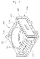
- FIG. 1 is a perspective view showing the appearance of a camera module according to the present invention.
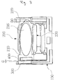
- FIG. 2 is a partial perspective view showing the internal construction of the cameral module from which a cover has been removed according to the present invention.
- FIG. 3 is a partial perspective view illustrating the cameral module of FIG. 2 , viewed from a different angle.
- FIG. 4 is an exploded perspective view of the camera module according to the present invention.
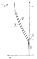
- FIG. 5 is a side view schematically illustrating the operation of a bobbin unit according to the present invention.
- FIG. 6 is a view illustrating alignment between a camera module and an image sensor according to the present invention. The construction and operation of the camera module of the present invention will be described in detail with reference to FIGS. 1 through 6 .
- the camera module of the present invention includes a drive unit 400 and 500, a base 100 and a bobbin unit 200.
- a structure capable of moving a lens in a direction of an optical axis (C0 of FIG. 4 ) is required.
- a rectangular coordination system is introduced, wherein the optical axis that corresponds to a center axis of the lens is defined as a Z-axis, and imaginary axes which form a plane perpendicular to the Z-axis are respectively defined as an X-axis and a Y-axis.
- the drive unit 400 and 500 can move a movable part 210 and a stationary part 220, which form the bobbin unit 200, with respect to each other.
- the drive unit 400 and 500 can be embodied by a variety of methods, for example, using an actuator.
- the drive unit 400 and 500 may comprise a coil 500 and a magnet 400.
- the coil 500 and the magnet 400 can provide moving force to the lens in such a way that when power is applied thereto, electromagnetic force is generated.
- the coil 500 and the magnet 400 are respectively installed on the base 100 and the bobbin unit 200.
- a lens drive means in which the coil 500 is attached to the bobbin unit 200 and is moved along with the lens is called a 'moving coil type lens drive means'
- a lens drive means in which the magnet 400 is attached to the bobbin unit 200 and is moved along with the lens is called a 'moving magnet type lens drive means'.
- Either the moving coil type or moving magnet type lens drive means can be used as the lens drive means of the present invention, and the moving magnet type lens drive means is used in the embodiment illustrated in the drawings.
- the coil 500 and the magnet 400 may be respectively installed on the stationary part 220 and the movable part 210 in the bobbin unit 200.
- opposite ends of the coil 500 are attached to respective coil seating surfaces 106 of base pillars 105 that protrude from the base 100.
- An adhesive is preferably used to provide reliable adhesive force.
- the magnet 400 which faces the coil 500 is attached to a magnet seating surface 206 formed in the movable part 210 of the bobbin unit 200. Referring to FIG. 3 , spaced apart from each other by a predetermined distance G, the coil 500 and the magnet 400 face each other.
- the predetermined distance G is appropriate if the magnet 400 attached to the movable part 210 does not interfere with the coil 500 when the movable part 210 moves upwards, downwards, leftwards or rightwards.
- the base 100 forms the appearance of the camera module.
- a cover 300 is coupled to the base 100. Either the coil 500 or the magnet 400 can be attached to the base 100.
- An opening formed in the base 100 faces an image sensor 600. Light reflected by a target enters the lens. Light that has entered the lens passes through the base 100 through the opening and reaches the image sensor 600 that is disposed below a lower surface of the base 100 with respect to the z-axial direction or in the lower surface of the base 100.
- the bobbin unit 200 is integrally provided.
- the bobbin unit 200 has the stationary part 220 which is fixed to the base 100, and the movable part 210 in which the lens is installed.
- the bobbin unit 200 is configured such that the movable part 210 is connected to the stationary part 220 so as to be movable relative to the stationary part 220.
- the relative movement of the movable part 210 may move the movable part 210 in the optical axis C0 upwards or downwards relative to the stationary part 220.
- the movable part 210 is connected to the stationary part 220 by suspension units 230.
- the suspension units 230 may be formed integrally with the movable part 210 and the stationary part 220 by a single mold at the same time.
- the suspension units 230 may be separately formed from the movable part 210 and the stationary part 220 before opposite ends of the suspension units 230 are respectively coupled to the movable part 210 and the stationary part 220. Therefore, unlike the conventional technique, despite providing no separate lens support means, the lens can be precisely supported by the connection structure of the suspension units 230 in the optical axial direction without tilting.
- the bobbin unit 200 is fixed at a first side thereof to the base 100.
- a second side of the bobbin unit 200 is used as the place where the lens is installed.
- the bobbin unit 200 is configured such that the first side of the bobbin unit 200 that is fixed to the base 100 and the second side of the bobbin unit 200 in which the lens is installed can move relative to each other.
- Either the coil 500 or the magnet 400 is attached to the second side of the bobbin unit 200 in which the lens is installed, whereby electromagnetic force can be applied to the second side of the bobbin unit 200.
- the stationary part 220 is a part that is fixed to the base 100, and the movable part 210 is a part to which either the coil 500 or the magnet 400 is attached and in which the lens is installed.
- the suspension units 230 function to elastically support the movable part 210 so that the movable part 210 can move with respect to the stationary part 220.
- the stationary part 220, the movable part 210 and the suspension units 230 can be integrally formed by a single mold at the same time.
- the stationary part 220, the movable part 210 and the suspension units 230 may be formed of the same material, for example, synthetic resin, rubber, etc., or, alternatively, they may be formed using an insert mold or outsert mold by injection molding such that a metal material can be partially contained therein.
- the stationary part 220, the movable part 210 and the suspension units 230 may be provided in such a way that they are formed as separate parts and then coupled to each other.
- the stationary part 220 fixed to the base 100 has a stationary part coupling hole 229 and stationary part pillars 225.
- a stationary part coupling rod 109 protrudes from the base 100.
- An additional UV adhesive or thermosetting adhesive is applied to coupling surfaces between the base 100 and the stationary part 220, thus providing vibration resistance and shock resistance.
- the stationary part pillars 225 function to guide the cover 300 when the cover 300 is assembled with the bobbin unit 200 and the base 100.
- four guide slots 305 formed in the respective corners of the cover 300 two guide slots 305 that correspond to the stationary part pillars 225 are fitted over the respective stationary part pillars 225.
- the cover 300 receives the bobbin unit 200, the coil 500 and the magnet 400 therein and is coupled to the base 100. If the cover 300 is made of a magnetic substance such as metal, it can also function as a yoke which prevents magnetic flux leakage.
- Hook slots 304 are formed in the cover 300.
- the hook slots 304 are locked to respective hooks 104 which are provided on the base 100, thus preventing the cover 300 from being undesirably removed from the base 100.
- Some of the guide slots 305 that are formed in the cover 300 are fitted over the base pillars 105 that protrude from the base 100, thus guiding the assembly position of the cover 300.
- the movable part 210 has a lens seating surface 216 onto which the lens is placed, and the magnet seating surface 206 onto which the magnet 400 is seated. To reduce installation space, a portion in which the lens seating surface 216 is disposed is cylindrical, and a portion in which the magnet seating surface 206 is disposed is planar.
- the optical axis C0 is the Z-axis.
- the coil 500 and the magnet 400 have surfaces which extend perpendicular to the X-axis and face each other with respect to the direction perpendicular to the X-axis.
- the suspension units 230 are respectively disposed at first and second sides of the X-axis and form an axial symmetric structure based on the X-axis. This restricts generation of rotational moment having the X-axis as a center axis, whereby even if the movable part 210 moves, a tilting angle ⁇ of the movable part 210 with respect to the optical axis C0 can be maintained constant.
- the suspension units 230 are respectively disposed at first and second sides of the Y-axis and form an axial symmetric structure based on the Y-axis.
- Each suspension unit 230 includes first and second links 231a and 231b, opposite ends of which are respectively connected to the stationary part 220 and the movable part 210.
- the first link 231a and the second link 231b are spaced apart from each other in the direction of the optical axis C0.
- the two links 231a and 231b have been illustrated as being provided at each of both sides of the bobbin unit 200, the structure in which the movable part 210 can maintain the tilting angle ⁇ constant while moving can be embodied so long as two or more links are provided at each side of the bobbin unit 200.
- FIG. 5 illustrates a structure in which, in each of the first and second sides of the bobbin unit 200, the suspension unit 230, the stationary part 220 and the movable part 210 form a parallelogram when the movable part 210 is moving. That is, an imaginary parallelogram, which has the first link 231a and the second link 231b as a pair of facing sides and has the stationary part 220 and the movable part 210 as another pair of facing sides, is formed. Thereby, the movable part 210 can maintain the tilting angle ⁇ with respect to the optical axis C0 constant while moving relative to the stationary part 220.
- each of the first and second sides of the bobbin unit 200 four hinge parts 210a, 210b, 220a and 220b are provided at positions which the opposite ends of the first links 231a and the opposite ends of the second link 231b are connected to the stationary part 220 and the movable part 210.
- each hinge part 210a, 210b, 220a, 220b is smaller than that of the first link 231a or the second link 231b.
- the hinge parts 210a, 210b, 220a and 220b are elastically changed in shape before the first link 231a and the second link 231b are. Therefore, a reduced-thickness part 234 is formed in each of the junctions between the opposite ends of the first and second links 231a and 231b and the hinge parts 210a, 210b, 220a and 220b.
- Each reduced-thickness part 234 has an inclined surface structure, which is gradually reduced in thickness from one end thereof to the other end, so as to prevent crack or fatigue failure.
- the coil 500 and the magnet 400 when viewed from the direction of the optical axis C0, the coil 500 and the magnet 400 are disposed at a position displaced from the optical axis C0 to one side. Unlike a conventional technique in which several coils and magnets are arranged at predetermined angles around the periphery of a bobbin, in the present invention, it is sufficient if the coil 500 and the magnet 400 are disposed on only one side of the bobbin unit 200. Therefore, this structure can contribute greatly to reducing the number of parts of the lens drive means and the production cost.
- the drive unit 400 and 500 can be embodied in various ways rather than being limited to the coil 500 and the magnet 400 illustrated in the drawings.
- the drive unit 400 and 500 may comprise a memory alloy, an ultrasonic vibrator or the like, although this is not shown in the drawings.
- Each suspension unit 230 has a shape of a both-end supported beam, the opposite ends of which are respectively connected to the stationary part 220 and the movable part 210.
- the suspension units 230 elastically support the movable part 210 in such a way that they are bent by electromagnet force applied between the coil 500 and the magnet 400.
- the suspension unit 230 includes the hinge parts 210a, 210b, 220a and 220b, the parts that are bent by electromagnet force are the hinge parts 210a, 210b, 220a and 220b.
- the first link 231a and the second link 231b have much higher strength than that of the hinge parts 210a, 210b, 220a and 220b so that the first and second links 231a and 231b along with the stationary part 220 and the movable part 210 can reliably form a parallelogram shape and thus the tilting angle ⁇ of the movable part 210 can be maintained constant.
- first link 231a and the second link 231b extend the same length and are rotated by the same angle by electromagnetic force generated between the coil 500 and the magnet 400.
- the movable part 210 can maintain the tilting angle ⁇ with respect to the optical axis C0 constant while moving relative to the stationary part 220.
- each of the first and second links 231a and 213b has a comparatively large cross-section so that it can substantially act as a rigid body, and a portion where elastic deformation including bending deformation occurs is limited to the hinge parts 210a, 210b, 220a and 220b that are partially provided.
- the manufacture and quality control of the bobbin unit 200 can be facilitated.
- a portion where quality control related to elasticity characteristics is required is limited to the hinge parts 210a, 210b, 220a and 220b, whereby elastic modulus deviation control can be facilitated.
- the tilting angle ⁇ of the movable part 210 can be reliably maintained constant.
- terminal units 102 are provided to supply power to the coil 500.
- Each terminal unit 102 includes an external extension 102a and an internal extension 102b.
- the external extension 102a extends outwards from the base 100 and is connected to an end of the coil 500 by soldering.
- the internal extension 102b extends towards the inside of the base 100 and pulls the magnet 400, which is attached to the movable part 210, towards the base 100, whereby the movable part 210 can begin to move from a state in which it has been maintained at the initial position.
- the terminal unit 102 having the above-mentioned shape becomes an embodiment a pre-load unit 102, 400 which is provided to maintain the lens at the initial position.
- the pre-load unit 102 and 400 can apply a pre-load to the movable part 210 in a direction towards the base 100.
- the direction towards the base 100 is a direction in which the lens approaches the image sensor 600.
- the pre-load unit includes the magnet and an attraction part which induces attraction force between it and the magnet using the pre-load.
- Either the magnet or the attraction part is installed on the movable part, and the other one of them is installed on the stationary part or the base.
- the pre-load unit includes the magnet 400 which is installed on the movable part 210, and the attraction part which is installed on the stationary part 220 or the base 100 and induces attraction force between it and the magnet 400 using a pre-load.
- the attraction part may be a magnetic body such as another magnet which can interact with the magnet and generate attraction force.
- the terminal unit 102 functions as the attraction part, and the magnet of the drive unit and the magnet of the pre-load unit are integrated with each other.
- the pre-load unit may comprise an elastic member such as an elastic plate 700.
- the pre-load unit when no power is applied to the coil 500 or when the camera module is not in operation, or when shock or vibration is applied to the camera module, the shock resistance of the movable part 210 with respect to the base 100 or the cover 300 can be enhanced. Further, when the camera module is operated, the pre-load unit makes it possible for the movable part 210 to begin to move at the initial position, whereby the position control can be facilitated.
- the movable part 210 is at a neutral position.
- Reference numeral P2 and the thin solid line designate the movable part 210 that has been pulled towards the base 100 and is in an initial position.
- Reference numeral P1 and the alternated long and short dash line designate the movable part 210 which has been moved upward and is focusing or is in a magnification control operation.
- a distance between the stationary part 220 and an end of the movable part 210 that faces the stationary part 220 is D0 when the movable part 210 is at the position P0.
- the distance is reduced to D1 at the position P1.
- the maximum value D0 of the distance is obtained when the movable part 210 is at the neutral position P0.
- the distance between the stationary part 220 and the end of the movable part 210 is set in consideration of a height at which the movable part 210 moves upwards or downwards.
- the tilting angle ⁇ of the movable part 210 with respect to the optical axis C0 can be maintained constant.
- FIG. 6 although a phenomenon in which the optical axis is shifted from C0 to C1 along the direction of the X-axis occurs, such a phenomenon in which the optical axis is shifted does not affect the quality of an image taken by the camera module, because the phenomenon does not distort the tilting angle ⁇ of the lens and the image sensor 600.
- the present invention can easily control the quality of the suspension unit 230, which pertains to upward or downward movement of the lens.
- the compensation for the tilting angle does not depend on a plate spring, not only can an assembly error be reduced but defective tilting can also be fundamentally prevented.
- the problem of a defective tilting angle is caused by a unit tolerance of each element.
- a defect that is called dynamic tilt is caused by an assembly tolerance which occurs when several elements are assembled with each other although the unit tolerance of each element is normal.
- the present invention is configured such that each link unit maintains a parallelogram shape while changing in shape. Therefore, the problem of a defective tilting angle attributable to a unit tolerance can be prevented, and dynamic tilt due to assembly tolerance can be fundamentally blocked.
- FIG. 7 is a view illustrating a camera module according to the present invention.
- FIG. 8 is a view illustrating another camera module according to the present invention.
- the camera module of FIG. 7 or 8 includes a bobbin unit 200 and suspension units 230.
- an elastic plate 700 is provided in the camera module.
- the bobbin unit 200 includes a stationary part 220 which is fixed on the base 100, and a movable part 210 which is moved relative to the stationary part 220 and in which a lens is installed.
- Each suspension unit 230 includes a link unit 231a and 231b.
- Opposite ends of the link unit 231a and 231b are respectively connected to the stationary part 220 and the movable part 210.
- the link unit 231a and 231b can be rotated when the movable part 210 moves relative to the stationary part 220.
- the link unit 231a and 231b can have a variety of shapes and comprise various numbers of links.
- the link unit 231a and 231b includes a first link 231a and a second link 231b. Opposite ends of each of the first and second links 231a and 231b are respectively connected to the stationary part 220 and the movable part 210.
- the first link 231a and the second link 231b are spaced apart from each other in the direction of the optical axis of the lens.
- the angle is an angle which is defined based on a direction perpendicular to the optical axis of the lens.
- the distance between the opposite ends of the first link 231a is the same as the distance between the opposite ends of the second link 231b.
- the stationary part 220, the movable part 210 and the suspension unit may be formed by a single mold at the same time or, alternatively, they may be separately formed before being assembled with each other.
- the suspension units 230 are respectively disposed at first and second sides of the bobbin unit 200 when viewed in a plan view.
- FIG. 7 or 8 illustrates the suspension units that are respectively disposed at two positions which have different values with respect to the Y-axial direction.
- the camera module includes a drive unit which moves the movable part 210 relative to the stationary part 220 in the direction of the optical axis of the lens and is disposed, based on the optical axis of the lens, on one side at which the link units 213a and 213b are connected to the movable part 210.
- the drive unit may include the coil and magnet that have been illustrated above.
- the drive unit may include a memory alloy, a solenoid, a piezo actuator, an ultrasonic vibrator or the like.
- Hinge parts each of which has a smaller cross-sectional area than that of that of the first link 231a or the second link 231b, are formed at respective positions at which the opposite ends of the first and second links 231a and 231b are connected to the stationary part 220 and the movable part 210.
- the hinge parts are elastically changed in shape when the movable part 210 moves.
- an imaginary parallelogram which has the first link 231a and the second link 231b as a pair of facing sides and has the stationary part 220 and the movable part 210 as another pair of facing sides, is formed.
- the movable part 210 can maintain the tilting angle with respect to the optical axis constant while moving relative to the stationary part 220.
- Each of the first and second links 231a and 231b may be formed in a both-end supported beam shape in such a way that the opposite ends thereof are respectively connected to the stationary part 220 and the movable part 210.
- the problem pertaining to tilting can be reliably solved by the simple construction, as explained in the description of the embodiment of FIGS. 1 through 6 .
- the elastic plate 700 is installed between the stationary part 220 and the movable part 210.
- the elastic plate 700 provides elastic force to the movable part 210 in the direction of the optical axis of the lens.
- the elastic force functions as a pre-load means which moves the movable part 210 in one direction of the optical axis of the lens.
- the direction of a pre-load generated by the elastic plate 700 may be a direction in which the movable part 210 approaches the base 100.
- the elastic plate 700 of the present invention does not only conduct the simple function of supporting the lens, unlike the plate spring (lens support means) of the conventional technique.
- the construction or shape of the elastic plate 700 also differs from those of the conventional plate spring.
- the elastic plate 700 of the present invention functions as a pre-load means for applying a pre-load to the movable part 210.
- the movable part 210 can be disposed at the initial position or reference position when the drive unit is not in operation.
- the elastic plate 700 may conduct only a function of supporting the movable part 210. This will be explained later herein.
- the elastic plate 700 may be formed in a both-ends supported beam shape in which the opposite ends thereof are respectively connected to the stationary part 220 and the movable part 210.
- the elastic plate 700 includes a first coupling part 710, a second coupling part 720 and an elastic part 730.
- the first coupling part 710 is coupled to the stationary part 220 fixed to the base 100.
- the second coupling part 720 is coupled to the movable part 210 which can move relative to the stationary part 220 and in which the lens is installed.
- the elastic part 730 connects the first coupling part 710 to the second coupling part 720 and is able to provide elastic force in the direction of the optical axis of the lens.
- the width of the first coupling part 710 is greater than that of the elastic part 730 so that the first coupling part 710 can be reliably coupled to the stationary part 220. If a depression/hole or protrusion which is coupled to the first coupling part 710 is provided in the stationary part 220, a protrusion or depression/hole corresponding to the depression/hole or protrusion of the stationary part 220 is formed in the first coupling part 710.
- the second coupling part 720 has a greater width than that of the elastic part 730 when viewed in the plan view so that the second coupling part 720 can be reliably coupled to the movable part 210.
- a depression/hole or protrusion which is coupled to the second coupling part 720 is provided in the movable part 210, a protrusion or depression/hole which corresponds to the depression/hole or protrusion of the movable part 210 is formed in the second coupling part 720.
- a first protrusion is provided on the stationary part 220, and a first hole into which the first protrusion is inserted is formed in the first coupling part 710.
- a second protrusion is provided on the movable part 210, and a second hole into which the second protrusion is inserted is formed in the second coupling part 720.
- the first coupling part 710, the second coupling part 720 and the elastic part 730 are disposed facing to a second surface of the stationary part 220 that is opposite to the first surface. From the viewpoint of a stacked structure, the base 100 - the stationary part 220 - the first coupling part 710, the second coupling part 720 and the elastic part 730 are successively disposed.
- the size of the camera module may be increased depending on installation space of the elastic plate 700.
- the elastic plate 700 is installed on a side surface of the camera module, the entire size of the camera module is naturally increased.
- the first coupling part 710, the second coupling part 720 and the elastic part 730 may be installed facing the first surface of the stationary part 220.
- the first coupling part 710, the second coupling part 720 and the elastic part 730 may be disposed between the base 100 and the stationary part 220.
- the coupling of the first coupling part 710 to the movable part 210 and the coupling of the second coupling part 720 to the stationary part 220 are complicated, whereby a problem may be caused during a manufacturing process.
- first coupling part 710, the second coupling part 720 and the elastic part 730 are disposed facing the second surface of the stationary part 220, an increase in the size of the camera module can be minimized.
- the second coupling part 720 is disposed at the side, at which the drive unit is disposed, based on the optical axis of the lens.
- the second coupling part 720 can also be disposed at the left side.
- the second coupling part 720 that is coupled to the movable part 210 is disposed at the right side that is opposite to the left side.
- a longitudinal direction of a line that passes through the first coupling part 710 and the second coupling part 720 almost correspond to the longitudinal direction of the first link 231a or the second link 231b.
- the first link 231a or the second link 231b can be prevented from being warped because of the elastic plate 700 while the first or second link 231a and 231b is operated.
- the first coupling part 710 is disposed at a position displaced from the optical axis of the lens to one side
- the second coupling part 720 is disposed at a position displaced from the optical axis of the lens to the other side.
- the first coupling part 710 preferably comprises a plurality of first coupling parts 710
- the second coupling part 720 also preferably comprises a plurality of second coupling parts 720.
- a first connection part 750 is provided to connect the first coupling parts 710 to each other
- a second connection part 760 is provided to connect the second coupling parts 720 to each other.
- the camera module two first coupling parts 710 and two second coupling parts 720 are provided, regarding the single movable part 210 and the single stationary part 220. Further, the camera module includes the first connection part 750 which connects the two first coupling parts 710 to each other.
- the first connection part 750 has a shape corresponding to an outer circumferential surface of the movable part 210 and is disposed adjacent to the outer circumferential surface of the movable part 210 at a position spaced apart from the movable part 210.
- the movable part 210 has a circular shape when viewed in the plan view, so that the first connection part 750 also has a circular shape.
- the diameter of the first connection part 750 is larger than that of the movable part 210, thus preventing the movement of the movable part 210 from being impeded by the first connection part 750. Furthermore, because the shape of the first connection part 750 corresponds to the outer circumferential surface of the movable part 210, an increase in the width of the camera module that results from the first connection part 750 can be minimized.
- the camera module may include the second connection part 760 which connects the two second coupling parts 720 to each other.
- the second connection part 760 can be coupled to at least a portion of the movable part 210.
- the movable part 210 has a circular shape when viewed in the plan view.
- the second connection part 760 is formed along a circle which has the same diameter as that of the outer circumferential surface of the movable part 210.
- the second connection part 760 is disposed on the movable part 210 with respect to the Z-axial direction and is attached to the movable part 210 by a means such as adhesive. To more reliably couple the second connection part 760 to the movable part 210, a separate coupling means may be provided.
- two protrusions 762 extend from the movable part 210 in the Z-axial direction. Holes 761 which are fitted over the corresponding protrusions 762 are formed in the second connection part 760 in radial directions of the circle defined by the second connection part 760.
- the assembly process can be facilitated, and the coupling force between the second connection part 760 and the movable part 210 can be enhanced.
- the first coupling part 710, the elastic part 730 and the second coupling part 720 form a cantilever structure to which the first coupling part 710 is coupled.
- the elastic part 730 can provide elastic force that biases the first coupling part 710 in one direction of the optical direction of the lens.
- the pre-load unit can have a simple and reliable structure and be embodied by a simple assembly process.
- the drive unit 400 and 500 moves the movable part 210 to the reference position when starting-up. After the movement of the movable part 210 to the reference position has been completed, the drive unit 400 and 500 moves the movable part 210 to a target position.
- FIG. 9 is a graph showing drive characteristics of the drive unit of an imaginary comparative embodiment for comparison with the present invention.
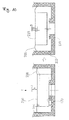
- FIG. 10 illustrates the camera module provided with a pre-load means according to the present invention.
- the elastic plate 700 described above, or the like can be used as the pre-load means.
- the drive unit may comprise an actuator.
- the horizontal axis of FIG. 9 designates current applied to the coil 500 which forms the actuator.
- the vertical axis of FIG. 9 designates an optical-axis-directional displacement of the bobbin unit 200 in which the magnet 400 that forms the actuator is installed.
- Reference numeral 770 denotes a section in which the movable part 210 is pre-loaded by the pre-load means.
- a TH threshold value
- the bobbin unit 200 is restricted from moving and is maintained in a state in which it has been placed on a seating portion 170 provided on the base 100.
- the seating portion 170 may be provided on the stationary part 220.
- Reference numeral 780 denotes a loading curve of the actuator.
- the loading curve of the actuator illustrates current-displacement characteristics of the actuator when the bobbin unit 200 moves forwards in the positive direction of the Z-axis as current applied to the coil 500 is increased.
- Reference numeral 790 denotes an unloading curve of the actuator.
- the unloading curve illustrates current-displacement characteristics of the actuator when the bobbin unit 200 moves backwards in the negative direction of the Z-axis as current applied to the coil 500 is reduced.
- a combination of the loading curve and the unloading curve forms a hysteresis curve that pertains to the drive characteristics of the actuator.
- the movable part 210 moves from the reference position to a target position for auto-focusing or auto-zoom.
- the pre-load means for holding the movable part 210 in the reference position may have a structure using a magnet or, alternatively, it may have a structure using an elastic plate 700.
- FIG. 10 illustrates the function of the pre-load means of the camera module.
- the elastic force of the elastic plate 700 may be used to dispose the movable part 210 at the reference position.
- the negative direction of the optical axis refers to a direction in which the movable part 210 moves from a free position, that is, from any position, to the reference position.
- the movable part 210 when no external force is applied to the elastic plate 700, if the junction between the elastic plate 700 and the movable part 210 is disposed at a position spaced apart from the position of the seating portion 170 by a distance a in the negative direction of the optical axis, the movable part 210 can be reliably pre-loaded on the seating portion 170. In this case, the elastic force that the movable part 210 must overcome while being moved to a target position D spaced apart from the reference position by a distance b is increased.
- k denotes the modulus of elasticity
- x denotes a displacement
- the camera module of the present invention may be configured such that when the camera module is operated, the movable part 210 is moved from a free position to the reference position and then moved from the reference position to the target position.
- the elastic plate 700 functions as a means for supporting the movable part 210 connected to the suspension unit 230, rather than functioning as the pre-load means.
- the movable part 210 when an auto-focusing or auto-zoom function is required while the movable part 210 is disposed at a free position (that may be the reference position or any position other than the reference position), the movable part 210 is first moved to the reference position. After the movable part 210 has been completely moved to the reference position, it is moved to the target position.
- the camera module includes the movable part 210 which is provided with the lens that catches a target and focuses on it to form an optical image, the suspension unit 230 or the elastic plate 700 which movably supports the movable part 210, and the seating portion 170 which functions as the reference position at which the movable part 210 is disposed at the initial operation stage.
- the movable part 210 has been illustrated being supported by the elastic plate 700, the movable part 210 may be supported by the suspension units 230 without using the elastic plate 700.
- the movable part 210 may be disposed at a position spaced apart from the seating portion 170 or placed on the seating portion 170 by the elastic plate 700. Further, the seating portion 170 is formed on the base 100.
- the elastic plate 700 If the elastic plate 700 is set such that the movable part 210 is disposed at a free position spaced apart form the seating portion 170 by a distance c, the elastic plate 700 functions to support the movable part 210 at the free position in lieu of functioning as the pre-load means.
- the movable part 210 is moved by the actuator to the seating portion 170 that corresponds to the reference position.
- the direction of the elastic force is the positive direction of the optical axis that is a direction towards a free position or target position. Therefore, to move the bobbin unit 200 in the negative direction of the optical axis that is a direction from the free position towards the reference position, a first power is supplied to the actuator.
- the first power has a first polarity, and the power of the first polarity is negative (-) power.
- the movable part 210 that has been moved to the reference position is moved to the target position D.
- a second power is supplied to the actuator.
- the second power has a second polarity that is opposite to the first polarity, and the power of the second polarity is positive (+) power.
- the present invention is not limited to the above-mentioned explanation.
- the first power may be positive (+) power as the first polarity
- the second power may be negative (-) power as the second polarity. That is, in the present invention that has no pre-load means, if the polarity of the first power by which the movable part 210 is moved from the free position to the reference position is different from that of the second power by which the movable part 210 is moved from the reference position to the target position, this can be an embodiment which falls within the bounds of the present invention. Because the bobbin unit 200 is moved upwards to the target position after being moved downwards to the reference position without using a separate pre-load means, power consumption can be reduced while auto-focusing, compared to the comparative embodiment using the pre-load means.
- the movable part 210 is moved for auto-focusing to the target position based on the reference position.
- the actuator when power is applied thereto, moves the movable part 210 in the direction of the optical axis.
- the camera module preferably includes a power unit 410 which applies power to the actuator.
- FIG. 11 illustrates the camera module provided with the power unit according to the present invention.
- the power unit 410 supplies power to the coil 500.
- the power unit 410 can apply first power and second power to the actuator.
- the first power and the second power are different from each other in polarity or absolute value.
- the power unit 410 may apply first power (e.g. negative (-) power) to the actuator and then apply second power (e.g. positive (+) power) thereto.
- first power e.g. negative (-) power
- second power e.g. positive (+) power
- the first power can be applied by voltage or current of negative polarity which moves the movable part 210 towards the seating portion that is the reference position.
- the second power can be applied by voltage or current of positive polarity which moves the movable part 210 towards the target position, that is, in a direction away from the seating portion.
- the power unit 310 includes a power generator 411 which generates power required to operate the bobbin unit 200 under the control of the control unit 430, and a polarity converter 413 which converts the polarity of the power generated from the power generator 411.
- the actuator when negative (-) power that is the first power is applied thereto, moves the movable part 210 from a free position to the reference position.
- positive (+) power that is the second power is applied to the actuator, it moves the movable part 210 from the reference position to the target position.
- the above-stated embodiment is the case where the free position of the movable part 210 corresponds to the reference position or approximately corresponds to the reference position and the target position is disposed at a position farther from the seating portion than is the free position. That is, based on the seating portion, the reference position, the free position and the target position are successively arranged.
- the polarity of the first power which moves the movable part 210 downwards from the free position to the reference position is preferably different from the polarity of the second power which moves the bobbin unit upwards from the reference position to the target position.
- the first power and the second power may have different absolute values while having the same polarity.
- the target position for auto-focusing is disposed between the free position and the reference position. Based on the seating portion, the reference position, the target position and the free position are successively arranged. If negative (-) power that moves the movable part 210 from the free position to the reference position is applied as the first power to the actuator, the second power which moves the movable part 210 from the reference position to the target position is negative (-) power that is the same polarity as the first power, and the absolute value of the second power is smaller than that of the first power.
- the second power which moves the movable part 210 from the reference position to the target position is positive (+) power that is the same polarity as the first power, and the absolute value of the second power is smaller than that of the first power.
- the actuator moves the movable part 210 to the reference position when first current having voltage of a first polarity is applied thereto.
- first current having voltage of a first polarity When second current having voltage of the first polarity or third current having voltage of second polarity is applied to the actuator, it moves the movable part 210 to the target position.
- the absolute value of the second current is smaller than that of the first current.
- the actuator may move the movable part 210 to the reference position when the first current having negative voltage is applied as the first power of negative (-) polarity to the actuator. Further, the actuator may move the movable part 210 to the target position when the second current having negative voltage is applied as the second power of negative (- ) polarity to the actuator or the third current having the positive voltage is applied as the second power of positive (+) polarity is applied thereto.
- the absolute value of the second current be less than the absolute value of the first current.
- the actuator may move the movable part 210 to the reference position when the first current having negative voltage is applied as the first power of positive (+) polarity to the actuator.
- the actuator may move the movable part 210 to the target position when the second current having positive voltage is applied as the second power of negative (+) polarity to the actuator or the third current having the negative voltage is applied as the second power of positive (-) polarity is applied thereto.
- the absolute value of the second current is less than the absolute value of the first current.
- the first power and the second power have different polarities, or if they have the same polarity, the absolute value of the second power is less than that of the first power.
- the camera module includes the seating portion 170 on which the movable part 210 is placed when it is moved to the reference position.
- the seating portion 170 may be formed on the base 100 or the stationary part 220.
- FIG. 12 is a graph showing the operation characteristics of the actuator which moves the movable part to the reference position and then moves it to the target position, according to an embodiment of the present invention.
- the horizontal axis of FIG. 12 denotes current applied to the coil 500
- the vertical axis denotes an optical-axis-directional displacement of the movable part 210.
- FIG. 12 shows a hysteresis curve while the movable part 210 that has been moved to the reference position is moved by the actuator between the reference position and the target position.
- FIG. 13 is a flowchart showing a method of controlling the camera module according to the present invention.
- the camera module control method can be described with reference to the operation of the camera module that has been described above.
- step S930 negative (-) power is supplied to the actuator which moves the movable part 210 in the direction of the optical axis so that the movable part 210 is moved to the reference position. This is an operation which is conducted in the power unit 410 and is controlled by the control unit 430.
- step S940 positive (+) power is supplied to the actuator so that the movable part 210 that has been moved to the reference position can be moved to the target position.
- the camera module control method may further include, when it is needed to determine the amount of negative (-) power required at the step of supplying the negative (-) power, step S920 of calculating the negative (-) power of the actuator required to move the movable part 210 from the free position to the reference position.
- the present invention provides a camera module which can reliably move a lens in a direction of an optical axis.
Landscapes
- Physics & Mathematics (AREA)
- General Physics & Mathematics (AREA)
- Optics & Photonics (AREA)
- Engineering & Computer Science (AREA)
- Multimedia (AREA)
- Signal Processing (AREA)
- Lens Barrels (AREA)
- Studio Devices (AREA)
- Adjustment Of Camera Lenses (AREA)
Applications Claiming Priority (1)
| Application Number | Priority Date | Filing Date | Title |
|---|---|---|---|
| KR20130051633A KR101494823B1 (ko) | 2013-05-08 | 2013-05-08 | 카메라 모듈 |
Publications (2)
| Publication Number | Publication Date |
|---|---|
| EP2802140A2 true EP2802140A2 (fr) | 2014-11-12 |
| EP2802140A3 EP2802140A3 (fr) | 2014-11-26 |
Family
ID=49726539
Family Applications (1)
| Application Number | Title | Priority Date | Filing Date |
|---|---|---|---|
| EP13195445.5A Withdrawn EP2802140A3 (fr) | 2013-05-08 | 2013-12-03 | Module à lentille pour caméra, avec support de lentille décalable parallèlement à l'axe optique |
Country Status (5)
| Country | Link |
|---|---|
| US (1) | US9179048B2 (fr) |
| EP (1) | EP2802140A3 (fr) |
| JP (1) | JP5825534B2 (fr) |
| KR (1) | KR101494823B1 (fr) |
| CN (1) | CN104142600A (fr) |
Cited By (2)
| Publication number | Priority date | Publication date | Assignee | Title |
|---|---|---|---|---|
| JP2016126186A (ja) * | 2015-01-05 | 2016-07-11 | キヤノン株式会社 | レンズ装置 |
| CN107615127A (zh) * | 2015-05-29 | 2018-01-19 | 三美电机株式会社 | 透镜驱动装置、摄像机模块、以及摄像机搭载装置 |
Families Citing this family (22)
| Publication number | Priority date | Publication date | Assignee | Title |
|---|---|---|---|---|
| CN117908213A (zh) * | 2013-12-04 | 2024-04-19 | Lg伊诺特有限公司 | 透镜驱动马达、摄像头模块和移动电话 |
| EP3002619B1 (fr) * | 2014-10-01 | 2018-01-17 | Axis AB | Procédé d'assemblage d'une caméra |
| USD753869S1 (en) * | 2015-02-02 | 2016-04-12 | C&D Zodiac, Inc. | Light cover |
| JP6500540B2 (ja) * | 2015-03-24 | 2019-04-17 | ミツミ電機株式会社 | レンズ駆動装置、カメラモジュール、及びカメラ搭載装置 |
| US9641731B2 (en) * | 2015-05-14 | 2017-05-02 | Corephotonics Ltd. | Unstable magnetic reluctance actuator |
| US10725313B2 (en) * | 2015-11-20 | 2020-07-28 | Mitsumi Electric Co., Ltd. | Lens driving device, camera module and camera mounting device having shake-correcting function and auto-focusing function |
| KR20170109193A (ko) | 2016-03-18 | 2017-09-28 | 삼성전기주식회사 | 카메라 모듈 |
| CN107277305B (zh) * | 2016-04-01 | 2020-10-09 | 台湾东电化股份有限公司 | 摄像模块及其控制方法 |
| KR101892853B1 (ko) * | 2016-10-04 | 2018-08-29 | 삼성전기주식회사 | 카메라 모듈의 액츄에이터 |
| US11163211B2 (en) | 2016-10-04 | 2021-11-02 | Samsung Electro-Mechanics Co., Ltd. | Camera module actuator |
| CN108319093B (zh) * | 2017-01-18 | 2021-08-06 | 三美电机株式会社 | 透镜驱动装置、摄像机模块以及摄像机搭载装置 |
| CN107483798B (zh) * | 2017-09-26 | 2020-07-31 | Oppo广东移动通信有限公司 | 用于终端设备的摄像头镜片组件以及终端 |
| CN109660703B (zh) * | 2017-10-12 | 2021-10-26 | 台湾东电化股份有限公司 | 光学机构的补正方法 |
| US10686993B2 (en) * | 2017-10-12 | 2020-06-16 | Tdk Taiwan Corp. | Correcting method for optical mechanism |
| USD902980S1 (en) * | 2018-01-12 | 2020-11-24 | Tdk Taiwan Corp. | Driving unit for a camera lens |
| KR102491569B1 (ko) * | 2018-01-17 | 2023-01-26 | 엘지이노텍 주식회사 | 렌즈 어셈블리 및 그를 포함하는 카메라 모듈 |
| KR102532317B1 (ko) * | 2018-05-23 | 2023-05-12 | 엘지이노텍 주식회사 | 렌즈 구동 장치, 이를 포함하는 카메라 모듈 및 광학 기기 |
| CN209928110U (zh) * | 2018-07-13 | 2020-01-10 | 台湾东电化股份有限公司 | 光学组件驱动机构及光学组件驱动系统 |
| CN111722348B (zh) * | 2019-03-20 | 2025-04-11 | 新思考电机有限公司 | 驱动装置、照相装置及电子设备 |
| KR102951670B1 (ko) * | 2020-03-19 | 2026-04-13 | 엘지이노텍 주식회사 | 렌즈 구동 장치 |
| CN116710840A (zh) * | 2021-01-26 | 2023-09-05 | 阿尔卑斯阿尔派株式会社 | 透镜驱动装置以及相机模块 |
| WO2023239034A1 (fr) * | 2022-06-10 | 2023-12-14 | 삼성전자주식회사 | Module de caméra et dispositif électronique le comprenant |
Family Cites Families (17)
| Publication number | Priority date | Publication date | Assignee | Title |
|---|---|---|---|---|
| US6389231B1 (en) * | 1999-06-23 | 2002-05-14 | Fuji Photo Optical Co., Ltd. | Lens driving apparatus, lens guiding mechanism, and optical instrument |
| JP2004118916A (ja) * | 2002-09-25 | 2004-04-15 | Sony Corp | アクチュエータ |
| GB0315273D0 (en) * | 2003-07-01 | 2003-08-06 | 1 Ltd | Lens suspension and actuation apparatus |
| JP2005165058A (ja) * | 2003-12-03 | 2005-06-23 | Sharp Corp | オートフォーカス装置 |
| KR100690361B1 (ko) * | 2005-06-02 | 2007-03-09 | 삼성전기주식회사 | 모바일용 액츄에이터 |
| JP4989063B2 (ja) * | 2005-11-24 | 2012-08-01 | キヤノン株式会社 | 位置制御装置およびそれを用いた光学機器 |
| KR100850544B1 (ko) * | 2006-12-13 | 2008-08-05 | 삼성전기주식회사 | 모바일 기기용 엑츄에이터 |
| GB0702897D0 (en) * | 2007-02-15 | 2007-03-28 | Johnson Electric Sa | Voice coil motor |
| KR101504350B1 (ko) * | 2007-09-07 | 2015-03-20 | 삼성전자주식회사 | 카메라 렌즈 모듈 |
| CN101526661B (zh) * | 2008-03-05 | 2011-11-09 | 鸿富锦精密工业(深圳)有限公司 | 镜头模组 |
| CN101576646B (zh) * | 2008-05-06 | 2012-09-19 | 鸿富锦精密工业(深圳)有限公司 | 微致动器组件、微致动器及镜头模组 |
| TWI426683B (zh) * | 2009-03-17 | 2014-02-11 | Vasstek Int Corp | A voice coil motor with a flat coil |
| KR101089926B1 (ko) * | 2009-11-04 | 2011-12-05 | 삼성전기주식회사 | 렌즈 이송 장치 |
| KR101070337B1 (ko) * | 2010-01-25 | 2011-10-06 | 자화전자 주식회사 | 카메라의 자동 초점 조정 장치 |
| KR101233572B1 (ko) * | 2011-04-19 | 2013-03-14 | 주식회사 뮤타스 | 카메라 모듈용 보이스 코일 모터 |
| WO2011132920A2 (fr) * | 2010-04-20 | 2011-10-27 | 주식회사 뮤타스 | Moteur à bobine mobile pour un module d'appareil photo |
| KR101170714B1 (ko) * | 2010-07-26 | 2012-08-03 | 자화전자 주식회사 | 자동 초점 엑츄에이터 및 이를 포함하는 카메라 모듈 |
-
2013
- 2013-05-08 KR KR20130051633A patent/KR101494823B1/ko not_active Expired - Fee Related
- 2013-12-03 CN CN201310641707.6A patent/CN104142600A/zh active Pending
- 2013-12-03 EP EP13195445.5A patent/EP2802140A3/fr not_active Withdrawn
- 2013-12-04 JP JP2013251361A patent/JP5825534B2/ja not_active Expired - Fee Related
- 2013-12-11 US US14/102,822 patent/US9179048B2/en not_active Expired - Fee Related
Non-Patent Citations (1)
| Title |
|---|
| None |
Cited By (2)
| Publication number | Priority date | Publication date | Assignee | Title |
|---|---|---|---|---|
| JP2016126186A (ja) * | 2015-01-05 | 2016-07-11 | キヤノン株式会社 | レンズ装置 |
| CN107615127A (zh) * | 2015-05-29 | 2018-01-19 | 三美电机株式会社 | 透镜驱动装置、摄像机模块、以及摄像机搭载装置 |
Also Published As
| Publication number | Publication date |
|---|---|
| EP2802140A3 (fr) | 2014-11-26 |
| US9179048B2 (en) | 2015-11-03 |
| KR20140132468A (ko) | 2014-11-18 |
| JP2014219654A (ja) | 2014-11-20 |
| CN104142600A (zh) | 2014-11-12 |
| JP5825534B2 (ja) | 2015-12-02 |
| US20140333829A1 (en) | 2014-11-13 |
| KR101494823B1 (ko) | 2015-02-23 |
Similar Documents
| Publication | Publication Date | Title |
|---|---|---|
| US9179048B2 (en) | Camera module | |
| KR102410030B1 (ko) | 광학 장치, 특히, 자동초점, 이미지 흔들림 방지 및 초-고해상도 기능을 포함하는 카메라 | |
| US11910090B2 (en) | Camera module actuator for optical image stabilization with movable image sensor | |
| US11513308B2 (en) | Camera module | |
| CN114514457B (zh) | 相机致动器和包括该相机致动器的相机模块 | |
| JP2008287034A (ja) | アクチュエータ、およびその製造方法、撮像機器、ならびに携帯電子機器 | |
| EP2863624B1 (fr) | Module de caméra et procédé d'alignement de l'axe optique du module de caméra. | |
| US20230185164A1 (en) | Camera module | |
| KR102840557B1 (ko) | 흔들림 보정용 액추에이터 및 이를 포함하는 카메라 모듈 | |
| KR102886407B1 (ko) | 카메라 액추에이터 및 이를 포함하는 카메라 장치 | |
| KR101801288B1 (ko) | 카메라 모듈 | |
| KR102888793B1 (ko) | 카메라 액추에이터 및 이를 포함하는 카메라 장치 | |
| KR101068124B1 (ko) | 카메라 모듈용 보이스 코일 모터 | |
| KR101233572B1 (ko) | 카메라 모듈용 보이스 코일 모터 | |
| CN111142214B (zh) | 具有光学防抖功能的自动对焦用透镜驱动装置 | |
| JP4262769B1 (ja) | アクチュエータ、撮像機器、及び電子機器 | |
| WO2011132920A2 (fr) | Moteur à bobine mobile pour un module d'appareil photo | |
| KR100620790B1 (ko) | 카메라 자동 초점 조절장치 | |
| KR102889651B1 (ko) | 카메라 액추에이터 및 이를 포함하는 카메라 모듈 | |
| KR100553534B1 (ko) | 카메라 자동 초점 조절장치용 리테이너 | |
| JP2021175992A (ja) | レンズ駆動装置、カメラモジュール及びカメラ搭載装置 | |
| KR100560051B1 (ko) | 카메라 자동 초점 조절장치용 하부커버 | |
| JP2023155194A (ja) | レンズ駆動装置、カメラ装置及び電子機器 | |
| JPWO2011027761A1 (ja) | レンズ駆動装置およびレンズ駆動装置を搭載したカメラモジュール、携帯電話 |
Legal Events
| Date | Code | Title | Description |
|---|---|---|---|
| PUAL | Search report despatched |
Free format text: ORIGINAL CODE: 0009013 |
|
| PUAI | Public reference made under article 153(3) epc to a published international application that has entered the european phase |
Free format text: ORIGINAL CODE: 0009012 |
|
| 17P | Request for examination filed |
Effective date: 20131203 |
|
| AK | Designated contracting states |
Kind code of ref document: A2 Designated state(s): AL AT BE BG CH CY CZ DE DK EE ES FI FR GB GR HR HU IE IS IT LI LT LU LV MC MK MT NL NO PL PT RO RS SE SI SK SM TR |
|
| AX | Request for extension of the european patent |
Extension state: BA ME |
|
| AK | Designated contracting states |
Kind code of ref document: A3 Designated state(s): AL AT BE BG CH CY CZ DE DK EE ES FI FR GB GR HR HU IE IS IT LI LT LU LV MC MK MT NL NO PL PT RO RS SE SI SK SM TR |
|
| AX | Request for extension of the european patent |
Extension state: BA ME |
|
| RIC1 | Information provided on ipc code assigned before grant |
Ipc: G03B 13/32 20060101ALI20141023BHEP Ipc: H04N 5/225 20060101ALI20141023BHEP Ipc: G03B 17/12 20060101ALI20141023BHEP Ipc: G02B 7/04 20060101ALI20141023BHEP Ipc: G02B 7/02 20060101ALI20141023BHEP Ipc: G03B 5/04 20060101ALI20141023BHEP Ipc: G02B 7/08 20060101ALI20141023BHEP Ipc: H04N 5/232 20060101AFI20141023BHEP Ipc: G02B 7/09 20060101ALI20141023BHEP Ipc: G03B 13/36 20060101ALI20141023BHEP Ipc: G03B 3/10 20060101ALI20141023BHEP |
|
| R17P | Request for examination filed (corrected) |
Effective date: 20150526 |
|
| RBV | Designated contracting states (corrected) |
Designated state(s): AL AT BE BG CH CY CZ DE DK EE ES FI FR GB GR HR HU IE IS IT LI LT LU LV MC MK MT NL NO PL PT RO RS SE SI SK SM TR |
|
| 17Q | First examination report despatched |
Effective date: 20150713 |
|
| GRAP | Despatch of communication of intention to grant a patent |
Free format text: ORIGINAL CODE: EPIDOSNIGR1 |
|
| INTG | Intention to grant announced |
Effective date: 20170127 |
|
| GRAS | Grant fee paid |
Free format text: ORIGINAL CODE: EPIDOSNIGR3 |
|
| STAA | Information on the status of an ep patent application or granted ep patent |
Free format text: STATUS: THE APPLICATION IS DEEMED TO BE WITHDRAWN |
|
| 18D | Application deemed to be withdrawn |
Effective date: 20170607 |