EP2802157A1 - Doppelformstrahl-Audio-Echo-Verminderung - Google Patents
Doppelformstrahl-Audio-Echo-Verminderung Download PDFInfo
- Publication number
- EP2802157A1 EP2802157A1 EP13167071.3A EP13167071A EP2802157A1 EP 2802157 A1 EP2802157 A1 EP 2802157A1 EP 13167071 A EP13167071 A EP 13167071A EP 2802157 A1 EP2802157 A1 EP 2802157A1
- Authority
- EP
- European Patent Office
- Prior art keywords
- audio
- echo
- audio beam
- signal
- microphones
- Prior art date
- Legal status (The legal status is an assumption and is not a legal conclusion. Google has not performed a legal analysis and makes no representation as to the accuracy of the status listed.)
- Granted
Links
Images


Classifications
-
- H—ELECTRICITY
- H04—ELECTRIC COMMUNICATION TECHNIQUE
- H04R—LOUDSPEAKERS, MICROPHONES, GRAMOPHONE PICK-UPS OR LIKE ACOUSTIC ELECTROMECHANICAL TRANSDUCERS; ELECTRIC HEARING AIDS; PUBLIC ADDRESS SYSTEMS
- H04R1/00—Details of transducers, loudspeakers or microphones
- H04R1/20—Arrangements for obtaining desired frequency or directional characteristics
- H04R1/32—Arrangements for obtaining desired frequency or directional characteristics for obtaining desired directional characteristic only
- H04R1/40—Arrangements for obtaining desired frequency or directional characteristics for obtaining desired directional characteristic only by combining a number of identical transducers
- H04R1/406—Arrangements for obtaining desired frequency or directional characteristics for obtaining desired directional characteristic only by combining a number of identical transducers microphones
-
- H—ELECTRICITY
- H04—ELECTRIC COMMUNICATION TECHNIQUE
- H04M—TELEPHONIC COMMUNICATION
- H04M9/00—Arrangements for interconnection not involving centralised switching
- H04M9/08—Two-way loud-speaking telephone systems with means for conditioning the signal, e.g. for suppressing echoes for one or both directions of traffic
-
- H—ELECTRICITY
- H04—ELECTRIC COMMUNICATION TECHNIQUE
- H04R—LOUDSPEAKERS, MICROPHONES, GRAMOPHONE PICK-UPS OR LIKE ACOUSTIC ELECTROMECHANICAL TRANSDUCERS; ELECTRIC HEARING AIDS; PUBLIC ADDRESS SYSTEMS
- H04R2410/00—Microphones
- H04R2410/01—Noise reduction using microphones having different directional characteristics
-
- H—ELECTRICITY
- H04—ELECTRIC COMMUNICATION TECHNIQUE
- H04R—LOUDSPEAKERS, MICROPHONES, GRAMOPHONE PICK-UPS OR LIKE ACOUSTIC ELECTROMECHANICAL TRANSDUCERS; ELECTRIC HEARING AIDS; PUBLIC ADDRESS SYSTEMS
- H04R3/00—Circuits for transducers
- H04R3/005—Circuits for transducers for combining the signals of two or more microphones
Definitions
- FIG. 1 illustrates a representative system, including a telephone device, for implementing a telephone conversation
- FIG. 3 illustrates a representative flow diagram for an apparatus using a plurality of beamformers for controlling modification of an audio signal
- adapted to describes hardware, software or a combination of hardware and software that is capable of, able to accommodate, to make, or that is suitable to carry out a given function.
- handheld is used to describe items, such as “handheld devices,” that are sized, shaped, designed or otherwise configured to be carried and operated while being held in a human hand.
- a device such as a portable cellular phone has a speakerphone operating mode for facilitating a telephone call between a near-end audio source and a far-end telephonic device.
- a network such as the public switched telephone network
- the portable cellular phone comprises a loudspeaker affixed to the cellular phone for annunciating the far-end audio signals from the far-end telephonic device and a plurality of microphones affixed to the cellular phone for receiving near-end audio signals from the near-end audio source and for receiving an echo signal generated by the loudspeaker.
- the audio processor also includes an echo reducer, coupled to at least one of the plurality of microphones (or beamforms) which receives a combination of the echo signal and the near end audio signals and operates to reduce the echo signal in response to the echo reduction control signal.
- the portable cellular phone also includes a wireless telephonic interface for coupling to the far-end telephonic device.
- a computer program product processes audio signals.
- the computer program product comprises a computer readable storage medium having computer readable program code embodied therewith.
- the computer readable program code comprises instructions for receiving a plurality of audio inputs from a corresponding plurality of microphones affixed to a telephone device.
- the telephone device also has a loudspeaker.
- the instructions further are for analyzing the first audio beam and the second audio beam and controlling a modification of an audio signal received by at least one of the plurality of microphones in response to the analyzing.
- Modification of the audio signal includes reducing an echo signal produced by the loudspeaker.
- a method comprises receiving a plurality of audio inputs from a corresponding plurality of microphones affixed to a telephone device having a loudspeaker and forming a first audio beam from the plurality of audio inputs, the first audio beam having a spatial null in the loudspeaker direction.
- the method also comprises forming a second audio beam from the plurality of audio inputs, the second audio beam having a spatial null in at least one near-end signal direction and analyzing the first audio beam and the second audio beam.
- the method also includes controlling a modification of an audio signal received by at least one of the plurality of microphones in response to the analyzing is also performed in the method.
- the modification to the audio signal includes reducing an echo signal generated by the loudspeaker.
- FIG. 1 illustrates a representative system, including a telephone device, for implementing a telephone conversation.
- the telephone device is embodied as a speakerphone 100, for purposes of illustration.
- Speakerphone 100 includes a loudspeaker(s) 102 affixed to the speakerphone and at least a first microphone 104 and a second microphone 106 included with a plurality of microphones which may number up to eight or more microphones.
- Loudspeaker(s) 102 may be comprised of one or more loudspeakers to enhance audio quality. While only a single loudspeaker is shown, multiple loudspeakers may provide for frequency or spatial diversity or both or stereophonic production of audio. Frequency diversity is used where the speakers have differing frequency ranges. Spatial diversity is where speakers are located in differing areas to provide for better production of sound.
- the microphones are shown to be affixed to the speakerphone, in other examples, the one or more of the microphones may be remote, and not affixed to the speakerphone.
- the telephone device may include any device that can function as a terminal for telephony (or that is adapted to facilitate telephonic communications), which may include telephony by wired or wireless channels or combinations thereof.
- a telephone device may include any of several kinds of customer-premises equipment or customer-provided equipment (CPE), and may include, for example, a portable telephone, a walkie-talkie, cell phone, smartphone, super phone, a desktop or conference room telephone, or a telephone application or process running within a personal digital assistant, tablet, laptop, personal computer.
- CPE customer-premises equipment
- speakerphone 100 need not be limited to a single functioning speakerphone and may also have a selectable handset mode where the user's head is in close proximity to the microphones and / or speaker.
- the microphones receive near-end audio signals 110 from desired sources such as one or more persons or talkers 111 (who may also be called near-end talkers) participating in a telephone conversation. Near-end signals may also include noise signals from sources such as fan 112. Near-end audio signals 110 are exchanged with far-end audio signals from far-end device 114 as part of a telephone conversation. Far-end audio signals are reproduced by loudspeaker 102 in order to be heard by persons 111. It is generally desirable that far-end audio signals, once they reach the near-end, stay at the near-end; it is generally undesirable that far-end audio signals reproduced by loudspeaker 102 be sent back to the far-end.
- the telephone conversation in this example is conducted through the Public Switched Telephone Network (PSTN) 116 via coupling 115.
- PSTN Public Switched Telephone Network
- the telephone conversation may be conducted through any other means for facilitating telephonic communications and need not be limited to the PSTN.
- Other means besides the PSTN include point to point or networked wired or wireless couplings such as USB, Ethernet, Bluetooth, WiFi, or Zigbee, local phone networks, local area networks, wide area networks, private networks, virtual private networks, intranets and the Internet.
- Beamform one, 134 is created by processing signals from the plurality of microphones and has a spatial null directed toward loudspeaker 102 (that is, the spatial null of beamform one, 134, is pointed or oriented in the loudspeaker direction). If loudspeaker 102 comprises more than one loudspeaker affixed to the housing, then beamform one can be created with multiple nulls in the direction of each of the speakers. If the speakers have frequency diversity, the spatial null locations can be frequency dependent corresponding to the frequency speaker.
- beamform one can be created with a high frequency null in the direction of the first speaker and a low frequency null in the direction of the second speaker.
- Beamform two, 136 is also created by processing signals from the microphones and has a spatial null directed toward near-end signals 110. The spatial null of beamform one results in an area of weak reception around the loudspeaker and the spatial null of beamform two results in an area of weak reception around the near-end signals.
- the microphones not only receive near-end signals 110 but also receive echo signals from loudspeaker 102.
- the echo signals are also included in beamform one and beamform two.
- the Echo Return Loss (ERL) between the loudspeaker and beamform one corresponds to an estimated transfer function "H1" 124
- the ERL between the loudspeaker and beamform two corresponds to an estimated transfer function "H2", 126.
- ERL is a function known to those familiar with the art and results from the acoustic coupling between the loudspeaker and the microphones and reflections from the surroundings acoustic environment 130.
- ERL estimation is a process known to those familiar with the art and can be at least partially predetermined and adaptively estimated on the fly as a smoothed power ratio of the loudspeaker and microphone signals during far-end single talk state, where far-end signals are generated by the loudspeaker.
- ERL can be estimated in full-band for an echo reduction system operating in time-domain or in each individual sub-band (or a frequency bin) for an echo reducer operating in sub-band or frequency domain.
- the ratio of the two echo frequency responses H1/H2 at each frequency band (or bin) driving the decision logic can also be more accurately estimated as a smoothed power ratio of the beamform one and beamform two during far-end single talk state.
- Estimating echo transfer function between the beams is particularly advantageous when echo contains non-linear components due to loudspeaker non-linearity, because those may not be accounted when H1 and H2 are estimated using the loudspeaker reference signal (i.e. the signal driving loudspeaker).
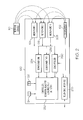
- FIG. 2 illustrates a representative block diagram including an apparatus using a plurality of beamformers for controlling modification of an audio signal.
- a plurality of beamformers 234 and 236 are coupled to a plurality of microphones 104, 106 and 208 affixed to a telephone device 100 having a loudspeaker 102.
- the second of the plurality of beamformers, beamform two, 236, is coupled to the plurality of microphones 104, 106, and 208 and forms a second audio beam having a spatial null in the direction of the near-end signals 110.
- An example of the second audio beam formed by beamformer two, 236 is shown as beamform two, 136 of FIG. 1 .
- Beamformer two may create a steerable beam having a spatial null that may be directed towards the near-end signals. If the near end signals are spread apart, for example if the fan 112 was some perpendicular distance from a talker 111, then a multiple spatial null beamform can be created with one spatial null directed towards noise source 112 and another spatial null directed towards talker 111.
- beamformer one and beamformer two are known to those familiar with the art (see for example, W. Kellermann, "Integrated Acoustic Echo Cancellation with Adaptive Beamforming Microphone Arrays” Forum Acusticum, Berlin, Germany, March 14, 1999 , H. Cox, R. M. Zeskind, and M. M. Owen, "Robust adaptive beamforming,” IEEE Trans. Acoust., Speech, Signal Processing, vol. 35, pp. 1365-1376, October 1987 , and O. L. Frost, III, "An algorithm for linearly constrained adaptive array processing," Proc. IEEE, vol. 60, pp. 926-935, August 1972 ) and involve processing and combining signals from the plurality of microphones to form a desired audio beam.
- the formation generally involves adjusting the magnitude and phase of microphone signals to form the desired beam either prior to on in combination with the combining of the microphone signals.
- the adjusting of the magnitude and phase may also be varied in response to the frequency of the microphone signals using either one broadband amplitude and phase adjustment, or multiple amplitude and phase adjustments based on frequency.
- beamform one and beamform two may be formed with a multitude of microphones, they may also be formed with as few as two microphones.
- the two beamformers allows for the concurrent formation of beamform one and beamform two. Beamforms one and two may be adaptive and may be independently steerable such that the spatial nulls may be directed in an appropriate direction based on the speakerphone surroundings, or may be preset in predetermined directions, which may be independent of each other.
- Controller 250 analyzes the output of the beamformers using ERL estimates H1, 124 and H2, 126 (or ERL between both beams, which is an echo transfer function H12) in order to control the modification of an audio signal received by at least one of the plurality of microphones.
- the modification will be described in more detail below.
- Controller 250 includes functions of a double-talk detector and a beamform analyzer and controls the operation of echo reducer 260, which may include an echo canceller, an echo suppressor and / or a residual echo suppressor.
- the construction and operation of echo reduction circuitry and processes are known to those familiar with the art (see for example Benesty et al., "Advances in Network and Acoustic Echo Cancellation” Berlin, Germany: Springer-Verlag, 2001 ).
- Echo reduction is performed on an audio signal received from at least one of the plurality of microphones or beams in response to audio signals provided to loudspeaker 102 by telephonic interface 270 and in response to signals received from the controller 250, the signals including an echo reduction control signal.
- the telephonic interface is known to those familiar with the art and may include any of the aforementioned wired and wireless interfaces for facilitation a telephone conversation.
- the controller 250 and the echo reducer 260 may be comprised within an integrated circuit which may include a processor such as Digital Signal Processor (DSP) executing program code instructions, which may be stored on a computer readable storage medium having computer readable program code embodied therewith, the computer readable program code comprising instructions for implementing at least portions of the controller or echo suppressor.
- the controller 250 and the echo reducer 260 may be at least partially comprised within an Application Specific Integrated Circuit (ASIC), a Field Programmable Array (FPGA), or semi-custom or custom designed circuit for implementing at least a portion of the controller or echo
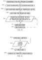
- FIG. 3 illustrates a representative flow diagram for an apparatus using a plurality of beamformers for controlling modification of an audio signal.
- Step 302 receives a plurality of audio inputs from a corresponding plurality of microphones, the microphones being affixed to device 100 and having a loudspeaker 102.
- Step 304 forms a first audio beam having a spatial null in the direction of the loudspeaker.
- Step 306 forms a second audio beam having a spatial null in the near-end signal direction.
- Step 308 then analyzes the first and second audio beams. Analysis of the first and second audio beams, which correspond to audio signals resulting from beamformers one and two respectively.
- the analysis may include determining the power in the first audio beam (Pb1) and the power in the second audio beam (Pb2), which may be limited to a narrow frequency range, a broad frequency, or a series of narrow frequency ranges.
- Step 310 determines if the power in the first audio beam is greater than the product of the power in the second audio beam and a preset criterion, the preset criterion being a function of the ratio of H1 and H2.
- beamform one has a beam pattern that is optimized for signal-to-echo ratio (SER). That is the pattern of beamform one is constrained to steer a null in the direction of the loudspeaker while providing for more uniform sound pickup of signals arriving in the direction of the near-end talker.
- SER signal-to-echo ratio
- Beamform two has a beam pattern that is optimized for echo-to-interference ratio (EIR) where echo is the desired signal and interference, in this case, is considered to be the near-end signals, because the near-end signals interfere with the detection of the echo signal.
- EIR echo-to-interference ratio
- Optimizing for EIR improves the estimation of the expected echo level to better facilitate the echo reduction processes.
- this also detects the loudspeaker signal components related to non-linear distortion during loud speakerphone playback. Detecting non-linear loudspeaker distortion provides a more accurate echo estimate at the frequencies of components produced by high volume loudspeaker distortion.
- the double-talk detection analysis can be determined by comparing the ratio of the two beamformer outputs to a threshold.
- the threshold in this example is a calculation of an approximately constant ratio of the two beamformer responses with respect to the source of the echo, the loudspeaker.
- the decision for the determination of a double-talk environment becomes the state when the power of beamform one is greater than the power of beamform two multiplied by the threshold, where the threshold is a function of the echo transfer functions of the two beamformers, or H1 and H2.
- the threshold is a function of the ratio of H1 and H2, or H1 / H2 in full-band or in each frequency band.
- this threshold is a function of the echo transfer function between the two beamformers.
- This threshold can be measured offline or estimated dynamically during periods of far-end signal talk.
- the ratio is treated as if it is relatively constant because variation in the acoustic echo path between the loudspeaker and each microphone due to changes in the acoustic environment may at least partially compensate for each other at the output of the two beamformers.
- echo reduction processes are either enabled or disabled in response to the determination. In other examples, the echo reduction process can be modified in response to the determination.
- FIG. 4 illustrates a representative flow diagram for an apparatus modifying an echo reduction process using a beamformed signal.
- Step 402 analyzes the beamform two to determine if the near-end signal interference level is low at step 404. Since beamform two directs a null towards the near-end signals, the EIR is improved and the echo signal is more detectible than it would be with a non-directional microphone because interference from near-end signals is reduced.
- Step 406 determines an unknown flat delay corresponding to a delay between the echo reducer reference signal from telephonic interface (270) and the input signals from plurality of microphones (104, 106, 208).
- the construction and operation of the delay estimator is known to those familiar with the art (see for example, D.
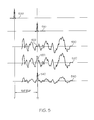
- FIG. 5 illustrates representative waveform examples related to the flow diagram of FIG. 4 .
- Waveform 500 shows a representative impulse waveform generated at the echo reducer's reference signal point before being processed for playback through the loudspeaker at a time T1.
- the signal processing such as: buffering in the DSP) and electrical components between the echo reference point and the loudspeaker (such as amplifiers and digital-to-analog converter) as well as analog-to-digital converter, amplifiers and buffering between the microphone signals and the input to the echo reducer can introduce additional echo path delay.
- Waveform 520 shows an example of a waveform resulting from the near-end audio signal present the vicinity of at least one of the plurality of microphones.
- Impulse waveform 510 is not included in waveform 520.
- waveform portion 522 shows a substantial flat and low energy component at T2.
- Waveform 530 shows the combination of waveform 510 and waveform 520 in the vicinity of the speaker phone. Such a waveform may be received by one of the plurality of microphones.
- waveform portion 532 shows the impulse component 510 added to waveform portion 522.
- Inspection of waveform 530 shows that the echo component is difficult to distinguish from the near-end component of the signals received by a microphone of the speaker phone because echo component is at approximately the same level as the near-end component and the near-end component interferes with the detection of the echo component. This is also an example of double-talk where the echo signal is at approximately the same level as the near-end signal.
- Waveform 540 shows a representative waveform received on beamform two. The spatial null in the direction of the near-end signals attenuates the near end signals allowing the echo to have a substantially greater magnitude.
- This greater magnitude echo signal facilitates the determination of the flat delay, or the delay between T1 and T2, even though the echo signal and the near-end signals are of similar magnitude in the vicinity of the speakerphone.
- the flat delay can be used by the echo reduction process to either enhance echo reduction or simplify echo processing.
- some echo canceling processes use an adaptive filter with multiple impulse response taps for modeling a presence of a delayed echo signal at various times.
- the output of each tap is processed for an echo signal.
- the output of several taps are known to be zero as a result of the flat delay information provided by the process shown in FIG. 4 .
- Information related to the flat delay may provide more processing power and additional magnitude and delay information for better echo modeling and echo reduction or suppression determinations in the region of the flat delay, or may provide more processing power for other audio processing or beamforming tasks, or may conserve power and improve the battery life of a battery powered speakerphone.
- controller 250 and echo reducer 260 may be comprised within an audio processor which also is capable of noise cancellation and determination of non-linearity in the echo signal.
- the audio processor may use these determinations to further modify the audio signal received by at least one microphone and sent to the far-end of the telephone call.
- FIG. 6 illustrates a representative block diagram of an electronic device and associated components 700 that is able to include the above described systems and perform the above described methods.
- an electronic device 752 is a wireless two-way communication device, such as a smartphone, with voice and data communication capabilities. Such electronic devices communicate with a wireless network 750, which is able to include a wireless voice network, a wireless data network, or both, that use one or more wireless communications protocols. Wireless voice communications are performed using either an analog or digital wireless communication channel. Data communications allow the electronic device 752 to communicate with other computer systems via the Internet.
- the illustrated electronic device 752 is an example electronic device that includes two-way wireless communications functions.
- Such electronic devices incorporate a wireless communication component that includes a wireless communications subsystem including elements such as a wireless transmitter 710, a wireless receiver 712, and associated components such as one or more antenna elements 714 and 716.
- a digital signal processor (DSP) 708 performs processing to extract data from received wireless signals and to generate signals to be transmitted.
- DSP digital signal processor
- the electronic device 752 in one example further includes an orientation sensor 754.
- Various electronic devices are able to incorporate one or more orientation sensors that include, for example, accelerometer or gyroscope based orientation sensors, light sensors that are located at locations on a case of the electronic device.
- the orientation sensor produces an indication of the current orientation of the electronic device relative to the ground.
- the electronic device 752 in one example includes an audio subsystem 746 that includes an audio processor 744, and a plurality of microphones 742.
- the plurality of microphones may include microphones 104, 106 and optional microphones 208 of FIG. 2 .
- an audio processor 744 in one example receives a voice signal representing echo signals and near-end signals, and performs processing to reduce the echo signal.
- the audio processor 744 may be an ASIC, FPGA or DSP or other type integrated circuit and be adapted to implement beamformer one, 234, beamformer two 236, controller 250 and echo reducer 260 of FIG. 2 .
- the USB port 728 provides data communication between the electronic device 752 and one or more external devices. Data communication through USB port 728 enables a user to set preferences through the external device or through a software application and extends the capabilities of the device by enabling information or software exchange through direct connections between the electronic device 752 and external data sources rather than through a wireless data communication network.
- the software exchange can be with microprocessor 702 or audio processor 744 or both as circumstances require.
- Operating system software used by the microprocessor 702 is stored in flash memory 706. Further examples are able to use a power pack backed-up RAM or other non-volatile storage data elements to store operating systems, other executable programs, or both.
- the operating system software, device application software, or parts thereof, are able to be temporarily loaded into volatile data storage such as RAM 704. Data received via wireless communication signals or through wired communications are also able to be stored to RAM 704.
- the microprocessor 702 in addition to its operating system functions, is able to execute software applications on the electronic device 752.
- PIM personal information manager
- Further applications may also be loaded onto the electronic device 752 through, for example, the wireless network 750, an auxiliary I/O device 738, USB port 728, short-range communications subsystem 720, or any combination of these interfaces. Such applications are then able to be installed by a user in the RAM 704 or a non-volatile store for execution by the microprocessor 702.
- a received signal such as a text message or web page download is processed by the communication subsystem, including wireless receiver 712 and wireless transmitter 710, and communicated data is provided the microprocessor 702, which is able to further process the received data for output to the display 734, or alternatively, to an auxiliary I/O device 738 or the USB port 728.
- a user of the electronic device 752 may also compose data items, such as e-mail messages, using the keyboard 736, which is able to include a complete alphanumeric keyboard or a telephone-type keypad, in conjunction with the display 734 and possibly an auxiliary I/O device 738. Such composed items are then able to be transmitted over a communication network through the communication subsystem.
- voice communications For voice communications, overall operation of the electronic device 752 is substantially similar, except that received signals are generally provided to a loudspeaker 732 and signals for transmission are generally produced by at least one of the plurality of microphones 742.
- Alternative voice or audio I/O subsystems such as a voice message recording subsystem, may also be implemented on the electronic device 752.
- voice or audio signal output is generally accomplished primarily through the loudspeaker 732, the display 734 may also be used to provide an indication of the identity of a calling party, the duration of a voice call, or other voice call related information, for example.
- one or more particular functions associated with a subsystem circuit may be disabled, or an entire subsystem circuit may be disabled. For example, if the power pack temperature is high, then voice functions may be disabled, but data communications, such as e-mail, may still be enabled over the communication subsystem.
- a short-range communications subsystem 720 is a further optional component which may provide for communication between the electronic device 752 and different systems or devices, which need not necessarily be similar devices.
- the short-range communications subsystem 720 may include an infrared device and associated circuits and components or a Radio Frequency based communication module such as one supporting Bluetooth ® communications, to provide for communication with similarly-enabled systems and devices.
- a media reader 760 is able to be connected to an auxiliary I/O device 738 to allow, for example, loading computer readable program code of a computer program product into the electronic device 752 for storage into flash memory 706 or in memory of audio processor 744.
- a media reader 760 is an optical drive such as a CD/DVD drive, which may be used to store data to and read data from a computer readable medium or storage product such as computer readable storage media 762.
- suitable computer readable storage media include optical storage media such as a CD or DVD, magnetic media, or any other suitable data storage device.
- Media reader 760 is alternatively able to be connected to the electronic device through the USB port 728 or computer readable program code is alternatively able to be provided to the electronic device 752 through the wireless network 750.
- the present subject matter can be realized in hardware, software, or a combination of hardware and software.
- a system can be realized in a centralized fashion in one computer system, or in a distributed fashion where different elements are spread across several interconnected computer systems. Any kind of computer system - or other apparatus adapted for carrying out the methods described herein - is suitable.
- a typical combination of hardware and software could be a general purpose computer system with a computer program that, when being loaded and executed, controls the computer system such that it carries out the methods described herein.
- the present subject matter can also be embedded in a computer program product, which comprises all the features enabling the implementation of the methods described herein, and which - when loaded in a computer system - is able to carry out these methods.
- Computer program in the present context means any expression, in any language, code or notation, of a set of computer instructions intended to cause a system having an information processing capability to perform a particular function either directly or after either or both of the following a) conversion to another language, code or, notation; and b) reproduction in a different material form.
- Each computer system may include, inter alia, one or more computers and at least a computer readable medium allowing a computer to read data, instructions, messages or message packets, and other computer readable information from the computer readable medium.
- the computer readable medium may include computer readable storage medium embodying non-volatile memory, such as read-only memory (ROM), flash memory, disk drive memory, CD-ROM, and other permanent storage. Additionally, a computer medium may include volatile storage such as RAM, buffers, cache memory, and network circuits.
- the computer readable medium may comprise computer readable information in a transitory state medium such as a network link and/or a network interface, including a wired network or a wireless network, that allow a computer to read such computer readable information.
Landscapes
- Health & Medical Sciences (AREA)
- Otolaryngology (AREA)
- Engineering & Computer Science (AREA)
- Signal Processing (AREA)
- Physics & Mathematics (AREA)
- Acoustics & Sound (AREA)
- Telephone Function (AREA)
- Circuit For Audible Band Transducer (AREA)
Priority Applications (1)
| Application Number | Priority Date | Filing Date | Title |
|---|---|---|---|
| EP13167071.3A EP2802157B1 (de) | 2013-05-08 | 2013-05-08 | Doppelformstrahl-Audioechoverminderung |
Applications Claiming Priority (1)
| Application Number | Priority Date | Filing Date | Title |
|---|---|---|---|
| EP13167071.3A EP2802157B1 (de) | 2013-05-08 | 2013-05-08 | Doppelformstrahl-Audioechoverminderung |
Publications (2)
| Publication Number | Publication Date |
|---|---|
| EP2802157A1 true EP2802157A1 (de) | 2014-11-12 |
| EP2802157B1 EP2802157B1 (de) | 2019-08-21 |
Family
ID=48325470
Family Applications (1)
| Application Number | Title | Priority Date | Filing Date |
|---|---|---|---|
| EP13167071.3A Active EP2802157B1 (de) | 2013-05-08 | 2013-05-08 | Doppelformstrahl-Audioechoverminderung |
Country Status (1)
| Country | Link |
|---|---|
| EP (1) | EP2802157B1 (de) |
Cited By (3)
| Publication number | Priority date | Publication date | Assignee | Title |
|---|---|---|---|---|
| WO2023133513A1 (en) * | 2022-01-07 | 2023-07-13 | Shure Acquisition Holdings, Inc. | Audio beamforming with nulling control system and methods |
| US12501207B2 (en) | 2019-11-01 | 2025-12-16 | Shure Acquisition Holdings, Inc. | Proximity microphone |
| US12598261B2 (en) | 2022-09-28 | 2026-04-07 | Shure Acquisition Holdings, Inc. | Wideband doubletalk detection for optimization of acoustic echo cancellation |
Citations (2)
| Publication number | Priority date | Publication date | Assignee | Title |
|---|---|---|---|---|
| US20050047611A1 (en) * | 2003-08-27 | 2005-03-03 | Xiadong Mao | Audio input system |
| US20120243698A1 (en) * | 2011-03-22 | 2012-09-27 | Mh Acoustics,Llc | Dynamic Beamformer Processing for Acoustic Echo Cancellation in Systems with High Acoustic Coupling |
-
2013
- 2013-05-08 EP EP13167071.3A patent/EP2802157B1/de active Active
Patent Citations (2)
| Publication number | Priority date | Publication date | Assignee | Title |
|---|---|---|---|---|
| US20050047611A1 (en) * | 2003-08-27 | 2005-03-03 | Xiadong Mao | Audio input system |
| US20120243698A1 (en) * | 2011-03-22 | 2012-09-27 | Mh Acoustics,Llc | Dynamic Beamformer Processing for Acoustic Echo Cancellation in Systems with High Acoustic Coupling |
Non-Patent Citations (6)
| Title |
|---|
| BENESTY ET AL.: "Advances in Network and Acoustic Echo Cancellation", 2001, SPRINGER-VERLAG |
| D. DUTTWEILER: "Subsampling to Estimate Delay with Application to Echo Cancelling", IEEE TRANSACTIONS ON ACOUSTICS AND SIGNAL PROCESSING, vol. ASSP-31, no. 5, October 1983 (1983-10-01) |
| H. COX; R. M. ZESKIND; M. M. OWEN: "Robust adaptive beamforming", IEEE TRANS. ACOUST., SPEECH, SIGNAL PROCESSING, vol. 35, October 1987 (1987-10-01), pages 1365 - 1376 |
| O. L. FROST, III: "An algorithm for linearly constrained adaptive array processing", PROC. IEEE, vol. 60, August 1972 (1972-08-01), pages 926 - 935 |
| W. KELLERMANN: "Integrated Acoustic Echo Cancellation with Adaptive Beamforming Microphone Arrays", FORUM ACUSTICUM, 14 March 1999 (1999-03-14) |
| Y. LE: "Enhancing Echo Cancellation via Estimation of Delay", IEEE TRANSACTIONS ON SIGNAL PROCESSING, vol. 53, no. 11, November 2005 (2005-11-01) |
Cited By (4)
| Publication number | Priority date | Publication date | Assignee | Title |
|---|---|---|---|---|
| US12501207B2 (en) | 2019-11-01 | 2025-12-16 | Shure Acquisition Holdings, Inc. | Proximity microphone |
| WO2023133513A1 (en) * | 2022-01-07 | 2023-07-13 | Shure Acquisition Holdings, Inc. | Audio beamforming with nulling control system and methods |
| US12250526B2 (en) | 2022-01-07 | 2025-03-11 | Shure Acquisition Holdings, Inc. | Audio beamforming with nulling control system and methods |
| US12598261B2 (en) | 2022-09-28 | 2026-04-07 | Shure Acquisition Holdings, Inc. | Wideband doubletalk detection for optimization of acoustic echo cancellation |
Also Published As
| Publication number | Publication date |
|---|---|
| EP2802157B1 (de) | 2019-08-21 |
Similar Documents
| Publication | Publication Date | Title |
|---|---|---|
| US9083782B2 (en) | Dual beamform audio echo reduction | |
| US11297178B2 (en) | Method, apparatus, and computer-readable media utilizing residual echo estimate information to derive secondary echo reduction parameters | |
| US10269369B2 (en) | System and method of noise reduction for a mobile device | |
| US9589556B2 (en) | Energy adjustment of acoustic echo replica signal for speech enhancement | |
| US9520139B2 (en) | Post tone suppression for speech enhancement | |
| US20110181452A1 (en) | Usage of Speaker Microphone for Sound Enhancement | |
| EP1051835B1 (de) | Erzeugung von kalibrierungssignalen zur adaptiven strahlbildung | |
| JP4046197B2 (ja) | 非線形回路のためのエコーキャンセラ | |
| EP2277323B1 (de) | Sprachverstärkung unter benutzung einer mehrzahl von mikrofonen an einer mehrzahl von geräten | |
| JP5394373B2 (ja) | オーディオ信号を処理する装置及び方法 | |
| US20190115040A1 (en) | Echo cancellation and suppression in electronic device | |
| US20130136274A1 (en) | Processing Signals | |
| US9508359B2 (en) | Acoustic echo preprocessing for speech enhancement | |
| US8811602B2 (en) | Full duplex speakerphone design using acoustically compensated speaker distortion | |
| US20080112568A1 (en) | Echo Canceller and Communication Audio Processing Apparatus | |
| US9813808B1 (en) | Adaptive directional audio enhancement and selection | |
| CN101278337A (zh) | 噪声环境中语音信号的健壮分离 | |
| WO2006012578A2 (en) | Separation of target acoustic signals in a multi-transducer arrangement | |
| WO2008041878A2 (en) | System and procedure of hands free speech communication using a microphone array | |
| US11205437B1 (en) | Acoustic echo cancellation control | |
| US20150086006A1 (en) | Echo suppressor using past echo path characteristics for updating | |
| EP2802157B1 (de) | Doppelformstrahl-Audioechoverminderung | |
| Papp et al. | Hands-free voice communication with TV | |
| CN102970638B (zh) | 处理信号 | |
| Kobayashi et al. | A hands-free unit with noise reduction by using adaptive beamformer |
Legal Events
| Date | Code | Title | Description |
|---|---|---|---|
| PUAI | Public reference made under article 153(3) epc to a published international application that has entered the european phase |
Free format text: ORIGINAL CODE: 0009012 |
|
| 17P | Request for examination filed |
Effective date: 20130508 |
|
| AK | Designated contracting states |
Kind code of ref document: A1 Designated state(s): AL AT BE BG CH CY CZ DE DK EE ES FI FR GB GR HR HU IE IS IT LI LT LU LV MC MK MT NL NO PL PT RO RS SE SI SK SM TR |
|
| AX | Request for extension of the european patent |
Extension state: BA ME |
|
| STAA | Information on the status of an ep patent application or granted ep patent |
Free format text: STATUS: EXAMINATION IS IN PROGRESS |
|
| 17Q | First examination report despatched |
Effective date: 20180827 |
|
| GRAP | Despatch of communication of intention to grant a patent |
Free format text: ORIGINAL CODE: EPIDOSNIGR1 |
|
| STAA | Information on the status of an ep patent application or granted ep patent |
Free format text: STATUS: GRANT OF PATENT IS INTENDED |
|
| RIC1 | Information provided on ipc code assigned before grant |
Ipc: H04R 1/40 20060101AFI20190213BHEP Ipc: H04M 9/08 20060101ALI20190213BHEP Ipc: H04R 3/00 20060101ALN20190213BHEP |
|
| RIC1 | Information provided on ipc code assigned before grant |
Ipc: H04M 9/08 20060101ALI20190215BHEP Ipc: H04R 1/40 20060101AFI20190215BHEP Ipc: H04R 3/00 20060101ALN20190215BHEP |
|
| INTG | Intention to grant announced |
Effective date: 20190312 |
|
| GRAS | Grant fee paid |
Free format text: ORIGINAL CODE: EPIDOSNIGR3 |
|
| GRAA | (expected) grant |
Free format text: ORIGINAL CODE: 0009210 |
|
| STAA | Information on the status of an ep patent application or granted ep patent |
Free format text: STATUS: THE PATENT HAS BEEN GRANTED |
|
| AK | Designated contracting states |
Kind code of ref document: B1 Designated state(s): AL AT BE BG CH CY CZ DE DK EE ES FI FR GB GR HR HU IE IS IT LI LT LU LV MC MK MT NL NO PL PT RO RS SE SI SK SM TR |
|
| REG | Reference to a national code |
Ref country code: GB Ref legal event code: FG4D |
|
| REG | Reference to a national code |
Ref country code: CH Ref legal event code: EP |
|
| REG | Reference to a national code |
Ref country code: DE Ref legal event code: R096 Ref document number: 602013059373 Country of ref document: DE |
|
| REG | Reference to a national code |
Ref country code: AT Ref legal event code: REF Ref document number: 1171103 Country of ref document: AT Kind code of ref document: T Effective date: 20190915 |
|
| REG | Reference to a national code |
Ref country code: IE Ref legal event code: FG4D |
|
| REG | Reference to a national code |
Ref country code: LT Ref legal event code: MG4D |
|
| REG | Reference to a national code |
Ref country code: NL Ref legal event code: MP Effective date: 20190821 |
|
| PG25 | Lapsed in a contracting state [announced via postgrant information from national office to epo] |
Ref country code: NO Free format text: LAPSE BECAUSE OF FAILURE TO SUBMIT A TRANSLATION OF THE DESCRIPTION OR TO PAY THE FEE WITHIN THE PRESCRIBED TIME-LIMIT Effective date: 20191121 Ref country code: HR Free format text: LAPSE BECAUSE OF FAILURE TO SUBMIT A TRANSLATION OF THE DESCRIPTION OR TO PAY THE FEE WITHIN THE PRESCRIBED TIME-LIMIT Effective date: 20190821 Ref country code: NL Free format text: LAPSE BECAUSE OF FAILURE TO SUBMIT A TRANSLATION OF THE DESCRIPTION OR TO PAY THE FEE WITHIN THE PRESCRIBED TIME-LIMIT Effective date: 20190821 Ref country code: BG Free format text: LAPSE BECAUSE OF FAILURE TO SUBMIT A TRANSLATION OF THE DESCRIPTION OR TO PAY THE FEE WITHIN THE PRESCRIBED TIME-LIMIT Effective date: 20191121 Ref country code: LT Free format text: LAPSE BECAUSE OF FAILURE TO SUBMIT A TRANSLATION OF THE DESCRIPTION OR TO PAY THE FEE WITHIN THE PRESCRIBED TIME-LIMIT Effective date: 20190821 Ref country code: FI Free format text: LAPSE BECAUSE OF FAILURE TO SUBMIT A TRANSLATION OF THE DESCRIPTION OR TO PAY THE FEE WITHIN THE PRESCRIBED TIME-LIMIT Effective date: 20190821 Ref country code: PT Free format text: LAPSE BECAUSE OF FAILURE TO SUBMIT A TRANSLATION OF THE DESCRIPTION OR TO PAY THE FEE WITHIN THE PRESCRIBED TIME-LIMIT Effective date: 20191223 Ref country code: SE Free format text: LAPSE BECAUSE OF FAILURE TO SUBMIT A TRANSLATION OF THE DESCRIPTION OR TO PAY THE FEE WITHIN THE PRESCRIBED TIME-LIMIT Effective date: 20190821 |
|
| PG25 | Lapsed in a contracting state [announced via postgrant information from national office to epo] |
Ref country code: AL Free format text: LAPSE BECAUSE OF FAILURE TO SUBMIT A TRANSLATION OF THE DESCRIPTION OR TO PAY THE FEE WITHIN THE PRESCRIBED TIME-LIMIT Effective date: 20190821 Ref country code: RS Free format text: LAPSE BECAUSE OF FAILURE TO SUBMIT A TRANSLATION OF THE DESCRIPTION OR TO PAY THE FEE WITHIN THE PRESCRIBED TIME-LIMIT Effective date: 20190821 Ref country code: GR Free format text: LAPSE BECAUSE OF FAILURE TO SUBMIT A TRANSLATION OF THE DESCRIPTION OR TO PAY THE FEE WITHIN THE PRESCRIBED TIME-LIMIT Effective date: 20191122 Ref country code: IS Free format text: LAPSE BECAUSE OF FAILURE TO SUBMIT A TRANSLATION OF THE DESCRIPTION OR TO PAY THE FEE WITHIN THE PRESCRIBED TIME-LIMIT Effective date: 20191221 Ref country code: LV Free format text: LAPSE BECAUSE OF FAILURE TO SUBMIT A TRANSLATION OF THE DESCRIPTION OR TO PAY THE FEE WITHIN THE PRESCRIBED TIME-LIMIT Effective date: 20190821 Ref country code: ES Free format text: LAPSE BECAUSE OF FAILURE TO SUBMIT A TRANSLATION OF THE DESCRIPTION OR TO PAY THE FEE WITHIN THE PRESCRIBED TIME-LIMIT Effective date: 20190821 |
|
| REG | Reference to a national code |
Ref country code: AT Ref legal event code: MK05 Ref document number: 1171103 Country of ref document: AT Kind code of ref document: T Effective date: 20190821 |
|
| PG25 | Lapsed in a contracting state [announced via postgrant information from national office to epo] |
Ref country code: TR Free format text: LAPSE BECAUSE OF FAILURE TO SUBMIT A TRANSLATION OF THE DESCRIPTION OR TO PAY THE FEE WITHIN THE PRESCRIBED TIME-LIMIT Effective date: 20190821 |
|
| PG25 | Lapsed in a contracting state [announced via postgrant information from national office to epo] |
Ref country code: IT Free format text: LAPSE BECAUSE OF FAILURE TO SUBMIT A TRANSLATION OF THE DESCRIPTION OR TO PAY THE FEE WITHIN THE PRESCRIBED TIME-LIMIT Effective date: 20190821 Ref country code: RO Free format text: LAPSE BECAUSE OF FAILURE TO SUBMIT A TRANSLATION OF THE DESCRIPTION OR TO PAY THE FEE WITHIN THE PRESCRIBED TIME-LIMIT Effective date: 20190821 Ref country code: DK Free format text: LAPSE BECAUSE OF FAILURE TO SUBMIT A TRANSLATION OF THE DESCRIPTION OR TO PAY THE FEE WITHIN THE PRESCRIBED TIME-LIMIT Effective date: 20190821 Ref country code: AT Free format text: LAPSE BECAUSE OF FAILURE TO SUBMIT A TRANSLATION OF THE DESCRIPTION OR TO PAY THE FEE WITHIN THE PRESCRIBED TIME-LIMIT Effective date: 20190821 Ref country code: PL Free format text: LAPSE BECAUSE OF FAILURE TO SUBMIT A TRANSLATION OF THE DESCRIPTION OR TO PAY THE FEE WITHIN THE PRESCRIBED TIME-LIMIT Effective date: 20190821 Ref country code: EE Free format text: LAPSE BECAUSE OF FAILURE TO SUBMIT A TRANSLATION OF THE DESCRIPTION OR TO PAY THE FEE WITHIN THE PRESCRIBED TIME-LIMIT Effective date: 20190821 |
|
| PG25 | Lapsed in a contracting state [announced via postgrant information from national office to epo] |
Ref country code: CZ Free format text: LAPSE BECAUSE OF FAILURE TO SUBMIT A TRANSLATION OF THE DESCRIPTION OR TO PAY THE FEE WITHIN THE PRESCRIBED TIME-LIMIT Effective date: 20190821 Ref country code: IS Free format text: LAPSE BECAUSE OF FAILURE TO SUBMIT A TRANSLATION OF THE DESCRIPTION OR TO PAY THE FEE WITHIN THE PRESCRIBED TIME-LIMIT Effective date: 20200224 Ref country code: SK Free format text: LAPSE BECAUSE OF FAILURE TO SUBMIT A TRANSLATION OF THE DESCRIPTION OR TO PAY THE FEE WITHIN THE PRESCRIBED TIME-LIMIT Effective date: 20190821 Ref country code: SM Free format text: LAPSE BECAUSE OF FAILURE TO SUBMIT A TRANSLATION OF THE DESCRIPTION OR TO PAY THE FEE WITHIN THE PRESCRIBED TIME-LIMIT Effective date: 20190821 |
|
| REG | Reference to a national code |
Ref country code: DE Ref legal event code: R097 Ref document number: 602013059373 Country of ref document: DE |
|
| PLBE | No opposition filed within time limit |
Free format text: ORIGINAL CODE: 0009261 |
|
| STAA | Information on the status of an ep patent application or granted ep patent |
Free format text: STATUS: NO OPPOSITION FILED WITHIN TIME LIMIT |
|
| PG2D | Information on lapse in contracting state deleted |
Ref country code: IS |
|
| 26N | No opposition filed |
Effective date: 20200603 |
|
| PG25 | Lapsed in a contracting state [announced via postgrant information from national office to epo] |
Ref country code: SI Free format text: LAPSE BECAUSE OF FAILURE TO SUBMIT A TRANSLATION OF THE DESCRIPTION OR TO PAY THE FEE WITHIN THE PRESCRIBED TIME-LIMIT Effective date: 20190821 |
|
| PG25 | Lapsed in a contracting state [announced via postgrant information from national office to epo] |
Ref country code: MC Free format text: LAPSE BECAUSE OF FAILURE TO SUBMIT A TRANSLATION OF THE DESCRIPTION OR TO PAY THE FEE WITHIN THE PRESCRIBED TIME-LIMIT Effective date: 20190821 Ref country code: CH Free format text: LAPSE BECAUSE OF NON-PAYMENT OF DUE FEES Effective date: 20200531 Ref country code: LI Free format text: LAPSE BECAUSE OF NON-PAYMENT OF DUE FEES Effective date: 20200531 |
|
| REG | Reference to a national code |
Ref country code: BE Ref legal event code: MM Effective date: 20200531 |
|
| PG25 | Lapsed in a contracting state [announced via postgrant information from national office to epo] |
Ref country code: LU Free format text: LAPSE BECAUSE OF NON-PAYMENT OF DUE FEES Effective date: 20200508 |
|
| PG25 | Lapsed in a contracting state [announced via postgrant information from national office to epo] |
Ref country code: IE Free format text: LAPSE BECAUSE OF NON-PAYMENT OF DUE FEES Effective date: 20200508 |
|
| PG25 | Lapsed in a contracting state [announced via postgrant information from national office to epo] |
Ref country code: BE Free format text: LAPSE BECAUSE OF NON-PAYMENT OF DUE FEES Effective date: 20200531 |
|
| PG25 | Lapsed in a contracting state [announced via postgrant information from national office to epo] |
Ref country code: MT Free format text: LAPSE BECAUSE OF FAILURE TO SUBMIT A TRANSLATION OF THE DESCRIPTION OR TO PAY THE FEE WITHIN THE PRESCRIBED TIME-LIMIT Effective date: 20190821 Ref country code: CY Free format text: LAPSE BECAUSE OF FAILURE TO SUBMIT A TRANSLATION OF THE DESCRIPTION OR TO PAY THE FEE WITHIN THE PRESCRIBED TIME-LIMIT Effective date: 20190821 |
|
| PG25 | Lapsed in a contracting state [announced via postgrant information from national office to epo] |
Ref country code: MK Free format text: LAPSE BECAUSE OF FAILURE TO SUBMIT A TRANSLATION OF THE DESCRIPTION OR TO PAY THE FEE WITHIN THE PRESCRIBED TIME-LIMIT Effective date: 20190821 |
|
| REG | Reference to a national code |
Ref country code: DE Ref legal event code: R082 Ref document number: 602013059373 Country of ref document: DE Ref country code: DE Ref legal event code: R081 Ref document number: 602013059373 Country of ref document: DE Owner name: MALIKIE INNOVATIONS LTD., IE Free format text: FORMER OWNER: BLACKBERRY LIMITED, WATERLOO, ONTARIO, CA |
|
| REG | Reference to a national code |
Ref country code: GB Ref legal event code: 732E Free format text: REGISTERED BETWEEN 20240620 AND 20240627 |
|
| PGFP | Annual fee paid to national office [announced via postgrant information from national office to epo] |
Ref country code: DE Payment date: 20250528 Year of fee payment: 13 |
|
| PGFP | Annual fee paid to national office [announced via postgrant information from national office to epo] |
Ref country code: FR Payment date: 20250526 Year of fee payment: 13 |
|
| PGFP | Annual fee paid to national office [announced via postgrant information from national office to epo] |
Ref country code: GB Payment date: 20260319 Year of fee payment: 14 |