EP2802177A1 - Basisstation, drahtloses endgerät, drahtloses kommunikationssystem und drahtloses kommunikationsverfahren - Google Patents
Basisstation, drahtloses endgerät, drahtloses kommunikationssystem und drahtloses kommunikationsverfahren Download PDFInfo
- Publication number
- EP2802177A1 EP2802177A1 EP12864614.8A EP12864614A EP2802177A1 EP 2802177 A1 EP2802177 A1 EP 2802177A1 EP 12864614 A EP12864614 A EP 12864614A EP 2802177 A1 EP2802177 A1 EP 2802177A1
- Authority
- EP
- European Patent Office
- Prior art keywords
- communication
- radio
- base station
- radio terminal
- validity period
- Prior art date
- Legal status (The legal status is an assumption and is not a legal conclusion. Google has not performed a legal analysis and makes no representation as to the accuracy of the status listed.)
- Granted
Links
Images


Classifications
-
- H—ELECTRICITY
- H04—ELECTRIC COMMUNICATION TECHNIQUE
- H04W—WIRELESS COMMUNICATION NETWORKS
- H04W52/00—Power management, e.g. Transmission Power Control [TPC] or power classes
- H04W52/02—Power saving arrangements
- H04W52/0209—Power saving arrangements in terminal devices
- H04W52/0212—Power saving arrangements in terminal devices managed by the network, e.g. network or access point is leader and terminal is follower
- H04W52/0216—Power saving arrangements in terminal devices managed by the network, e.g. network or access point is leader and terminal is follower using a pre-established activity schedule, e.g. traffic indication frame
-
- H—ELECTRICITY
- H04—ELECTRIC COMMUNICATION TECHNIQUE
- H04W—WIRELESS COMMUNICATION NETWORKS
- H04W76/00—Connection management
- H04W76/20—Manipulation of established connections
- H04W76/25—Maintenance of established connections
-
- H—ELECTRICITY
- H04—ELECTRIC COMMUNICATION TECHNIQUE
- H04W—WIRELESS COMMUNICATION NETWORKS
- H04W48/00—Access restriction; Network selection; Access point selection
- H04W48/08—Access restriction or access information delivery, e.g. discovery data delivery
- H04W48/10—Access restriction or access information delivery, e.g. discovery data delivery using broadcasted information
-
- H—ELECTRICITY
- H04—ELECTRIC COMMUNICATION TECHNIQUE
- H04W—WIRELESS COMMUNICATION NETWORKS
- H04W52/00—Power management, e.g. Transmission Power Control [TPC] or power classes
- H04W52/02—Power saving arrangements
- H04W52/0209—Power saving arrangements in terminal devices
- H04W52/0212—Power saving arrangements in terminal devices managed by the network, e.g. network or access point is leader and terminal is follower
- H04W52/0222—Power saving arrangements in terminal devices managed by the network, e.g. network or access point is leader and terminal is follower in packet switched networks
-
- H—ELECTRICITY
- H04—ELECTRIC COMMUNICATION TECHNIQUE
- H04W—WIRELESS COMMUNICATION NETWORKS
- H04W76/00—Connection management
- H04W76/20—Manipulation of established connections
- H04W76/28—Discontinuous transmission [DTX]; Discontinuous reception [DRX]
-
- Y—GENERAL TAGGING OF NEW TECHNOLOGICAL DEVELOPMENTS; GENERAL TAGGING OF CROSS-SECTIONAL TECHNOLOGIES SPANNING OVER SEVERAL SECTIONS OF THE IPC; TECHNICAL SUBJECTS COVERED BY FORMER USPC CROSS-REFERENCE ART COLLECTIONS [XRACs] AND DIGESTS
- Y02—TECHNOLOGIES OR APPLICATIONS FOR MITIGATION OR ADAPTATION AGAINST CLIMATE CHANGE
- Y02D—CLIMATE CHANGE MITIGATION TECHNOLOGIES IN INFORMATION AND COMMUNICATION TECHNOLOGIES [ICT], I.E. INFORMATION AND COMMUNICATION TECHNOLOGIES AIMING AT THE REDUCTION OF THEIR OWN ENERGY USE
- Y02D30/00—Reducing energy consumption in communication networks
- Y02D30/70—Reducing energy consumption in communication networks in wireless communication networks
Definitions
- the present invention relates to a base station, a radio terminal, a radio communication system, and a radio communication method that perform radio communication.
- a cellular communication system has become the mainstream of mobile communication systems for mobile phones and the like.
- the cellular communication system covers a wide area that includes a plurality of areas (cells), each of which is a communication range of a base station.
- cells each of which is a communication range of a base station.
- LTE-A LTE-Advanced
- a radio terminal In the interval during which no data is exchanged, it is preferable that a radio terminal be switched to an RRC (Radio Resource Control) idle state (standby state).
- RRC Radio Resource Control
- the radio terminal frequently switches between an RRC connected state (communicating state) and an idle state, so that the amount of RRC signaling increases. Therefore, the power consumed by the radio terminal increases.
- the present invention has been made in view of the above problem, and aims to provide a base station, a radio terminal, a radio communication system, and a radio communication method capable of reducing power consumption by the radio terminal.
- a base station that performs radio communication with a radio terminal.
- This base station includes: a transmitting unit configured to, when completing radio communication with the radio terminal, transmit to the radio terminal a validity period of control information on radio communication which has been used to communicate with the radio terminal; and a communication unit configured to, when starting radio communication with the radio terminal within the validity period, start radio communication with the radio terminal without performing a process of exchanging the control information.
- a radio terminal that performs radio communication with a base station.
- This radio terminal includes: a receiving unit configured to, when completing radio communication with the base station, receive from the base station a validity period of control information on radio communication which has been used to communicate with the base station; and a communication unit configured to, when starting radio communication with the base station within the validity period, start radio communication with the base station without performing a process of exchanging the control information.
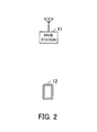
- FIG. 1 illustrates a radio communication system according to a first embodiment.
- a radio communication system includes a base station 1 and a radio terminal 2.
- the base station 1 includes a transmitting unit 1a and a communication unit 1b.
- the radio terminal 2 includes a receiving unit 2a and a communication unit 2b.
- the transmitting unit 1a of the base station 1 is configured to, when completing radio communication with the radio terminal 2, transmit to the radio terminal 2 a validity period of control information on radio communication which has been used to communicate with the radio terminal 2.
- the control information may be RRC parameters, for example.
- the transmitting unit 1a transmits to the radio terminal 2 a validity period, such as, for example, 5 minutes, of RRC parameters.
- the communication unit 1b is configured to, when starting radio communication with the radio terminal 2 within the validity period, start radio communication with the radio terminal 2 without performing a process of exchanging control information.
- the communication unit 1b starts radio communication with the radio terminal 2 without performing a process of exchanging RRC parameters (for example, a process of exchanging RRC parameters in a normal RRC connection).
- the communication unit 1b performs radio communication with the radio terminal 2, using the RRC parameters used for the previous radio communication.
- the communication unit 1b exchanges RRC parameters (for example, exchanges RRC parameters in a normal RRC connection) with the radio terminal 2, and then communicates with the radio terminal 2 using the RRC parameters.
- the receiving unit 2a of the radio terminal 2 is configured to, when completing radio communication with the base station 1, receive from the base station 1 a validity period of control information on radio communication which has been used to communicate with the base station 1. That is, the receiving unit 2a receives a validity period transmitted from the transmitting unit 1a of the base station 1.
- the communication unit 2b is configured to, when starting radio communication with the base station 1 within the validity period received by the receiving unit 2a, start radio communication with the base station 1 without performing a process of exchanging control information.
- control information is RRC parameters, as mentioned above.
- validity period received by the receiving unit 2a is 5 minutes. In this case, if 5 minutes have not elapsed from the completion of the previous radio communication, the communication unit 2b starts radio communication with the base station 1 without performing a process of exchanging RRC parameters.
- the communication unit 2b performs radio communication with the base station 1, using the RRC parameters used for the previous radio communication.
- the communication unit 2b exchanges RRC parameters (for example, exchanges RRC parameters in a normal RRC connection) with the base station 1, and then communicates with the base station 1 using the RRC parameters.
- the base station 1 is configured to, when completing radio communication with the radio terminal 2, transmit to the radio terminal a validity period of control information on radio communication which has been used to communicate with the radio terminal 2. Further, the base station 1 is configured to, when starting radio communication with the radio terminal 2 within the validity period, start radio communication with the radio terminal 2 without performing a process of exchanging control information with the radio terminal 2.
- the radio terminal 2 is configured to, when completing radio communication with the base station 1, receive from the base station 1 a validity period of control information on radio communication which has been used to communicate with the base station 1. Further, the radio terminal 2 is configured to, when starting radio communication with the base station 1 within the validity period, start radio communication with the base station 1 without performing a process of exchanging control information with the base station 1.
- the base station 1 and the radio terminal 2 do not perform a process of exchanging control information. This allows the radio terminal 2 to reduce the amount of signaling involved in the process of exchanging control informal, and thus to reduce power consumption.
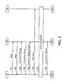
- FIG. 2 illustrates a radio communication system according to the second embodiment.
- a radio communication system includes a base station 11 and a radio terminal 12.
- the base station 11 and the radio terminal 12 perform radio communication in accordance with a radio communication standard, such as LTE-A, LTE, and so on, for example.
- a radio communication standard such as LTE-A, LTE, and so on, for example.
- the radio terminal 12 may be a smartphone or a mobile phone, for example. Prior to providing a detailed description of the base station 11 and the radio terminal 12, an RRC connection will be described.
- FIG. 3 is a sequence diagram illustrating an RRC connection.
- a conventional base station and a conventional radio terminal establish and release an RRC connection, and set and release RRC parameters each time the base station and radio terminal perform intermittent packet communication. Therefore, the radio terminal has an increased amount of RRC signaling and hence an increased power consumption.
- radio communication is performed using the RRC parameters used for the previous radio communication, without exchanging RRC parameters. This allows the radio terminal 12 to reduce the amount of RRC signaling, and thus to reduce power consumption, in intermittent data communication of small packets.
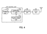
- FIG. 4 is a block diagram illustrating the base station.
- the base station 11 includes a control unit 21, a baseband unit 22, and a radio unit 23.
- the control unit 21 includes a validity period calculation unit 21a, a communication control unit 21b, and a storage unit 21c.
- the control unit 21 corresponds to, for example, the transmitting unit 1a and the communication unit 1b of FIG. 1 .
- the validity period calculation unit 21a calculates a validity period of RRC parameters. For example, the validity period calculation unit 21a calculates a validity period in accordance with the location of the radio terminal 12 in the cell of the base station 11.
- the validity period calculation unit 21a sets a longer validity period if the radio terminal 12 is located in the center of the cell, and sets a shorter validity period if the radio terminal 12 is located at the edge of the cell. This is because, if the radio terminal 12 is at the edge of the cell, the radio terminal 12 is highly likely to move to the cell of the adjacent base station, and therefore it is preferable to release RRC parameters. Further, the validity period calculation unit 21a may calculate the validity period taking into consideration the moving speed and direction of the radio terminal 12.
- the radio terminal 12 is able to determine its location using GPS (Global Positioning System), for example. Further, the radio terminal 12 is able to determine its moving speed and direction using an accelerometer, for example.
- the validity period calculation unit 21a receives location information from the radio terminal 12, and thus is able to determine the location of the radio terminal 12 in the cell. Further, the validity period calculation unit 21a receives the moving speed and direction from the radio terminal 12, and thus is able to determine the moving speed and direction of the radio terminal 12.
- the validity period calculation unit 21a may output a validity period of a constant length.
- the validity period calculation unit 21a may output a constant validity period, such as 5 minutes or the like, regardless of the location and the moving speed and direction of the radio terminal 12.
- the communication control unit 21b transmits to the radio terminal 12 the validity period calculated (output) by the validity period calculation unit 21a. That is, when completing radio communication with the radio terminal 12, the communication control unit 21b transmits to the radio terminal 12 the validity period of RRC parameters used for the radio communication with the radio terminal 12.
- the communication control unit 21b starts radio communication with the radio terminal 12 without performing a process of exchanging RRC parameters. Then, the communication control unit 21b performs radio communication with the radio terminal 12, using the RRC parameters used for the previous radio communication (RRC parameters stored in the storage unit 21c).
- the validity period is transmitted to the radio terminal 12 via the baseband unit 22 and the radio unit 23. Further, communication with the radio terminal 12 using RRC parameters is performed via the baseband unit 22 and the radio unit 23.
- the storage unit 21c stores RRC parameters that are generated when establishing an RRC connection.
- the storage unit 21c also stores RRC parameters used for the previous radio communication.
- the baseband unit 22 performs baseband processing on data to be transmitted to the radio terminal 12.
- the baseband unit 22 also performs baseband processing on data received from the radio terminal 12.
- the radio unit 23 performs radio processing on data to be transmitted to the radio terminal 12. For example, the radio unit 23 converts the frequency of data to be transmitted to the radio terminal 12 into a radio frequency. The radio unit 23 also performs radio processing on data received from the radio terminal 12. For example, the radio unit 23 converts the frequency of data received from the radio terminal 12 into a baseband frequency.
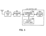
- FIG. 5 is a block diagram illustrating the radio terminal.
- the radio terminal 12 includes a control unit 31, a radio unit 32, and a baseband unit 33.
- the control unit 31 includes a communication control unit 31a, a validity period timer 31b, and a storage unit 31c.
- the control unit 31 corresponds to, for example, the receiving unit 2a and the communication unit 2b of FIG. 1 .
- the communication control unit 31a When completing radio communication with the base station 11, the communication control unit 31a receives from the base station 11 a validity period of RRC parameters used for the radio communication with the base station 11. The communication control unit 31a sets, for the validity period timer 31b, the received validity period. Note that the communication control unit 31a receives the validity period via the radio unit 32 and the baseband unit 33.
- the validity period timer 31b After completion of radio communication, when the validity period expires, the validity period timer 31b notifies the communication control unit 31a of the expiration of the validity period. For example, the validity period timer 31b reduces the validity period set by the communication control unit 31a in increments of one. When the validity period reaches 0, the validity period timer 31b notifies the communication control unit 31a of the expiration of the validity period.
- the storage unit 31c stores RRC parameters that are generated when establishing an RRC connection.
- the storage unit 31c also stores RRC parameters used for the previous radio communication.
- the communication control unit 31a When starting radio communication with the base station 11 within the validity period, the communication control unit 31a starts radio communication with the base station 11 without performing a process of exchanging RRC parameters. Then, the communication control unit 31a performs radio communication with the base station 11, using the RRC parameters stored in the storage unit 31c. For example, the communication control unit 31a sets a validity period in the validity period timer 31b. Then, if a notification indicating that the timer value has reached 0 is not received from the validity period timer 31b, the communication control unit 31a performs radio communication with the base station 11, using the RRC parameters stored in the storage unit 31c. Note that the communication control unit 31a performs radio communication with the base station 11 via the baseband unit 33 and the radio unit 32.
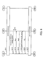
- FIG. 6 is a sequence diagram illustrating data communication.
- a UE corresponds to the radio terminal 12, and an eNB corresponds to the base station 11.
- the communication control unit 21b transmits a Connection Release to the radio terminal 12.
- the communication control unit 21b also transmits to the radio terminal 12 the validity period calculated by the validity period calculation unit 21a.
- the communication control unit 31a of the radio terminal 12 sets, for the validity period timer 31b, the validity period received from the base station 11.
- the communication control unit 31a transmits a Connection Request so as to establish an RRC connection to the base station 11 (for example, step S3 of FIG. 3 ).
- the communication control unit 31a performs re-setup of connection (re-setup of an RRC connection), instead of transmitting a Connection Request.
- the communication control unit 31a transmits a Connection Re-setup to the base station 11 so as to perform communication using the RRC parameters stored in the storage unit 31c.
- the communication control unit 21b of the base station 11 performs radio communication with the radio terminal 12, using the RRC parameters used for the previous radio communication (step S11) and stored in the storage unit 21c. Further, the communication control unit 31a of the radio terminal 12 performs radio communication with the radio terminal 12, using the RRC parameters used for the previous radio communication (step S11) and stored in the storage unit 31c.
- the base station 11 and the radio terminal 12 perform radio communication, using RRC parameters used for the previous radio communication, without performing a process of exchanging RRC parameters. This allows the base station 11 and the radio terminal 12 to reduce the amount of signaling between the base station 11 and the radio terminal 12, and thus allows the radio terminal 12 to reduce power consumption.
- FIG. 7 is a flowchart of a process performed by the base station when completing data communication.
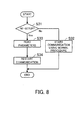
- FIG. 8 is a flowchart of a process performed by the base station when restarting data communication.
- the radio terminal 12 transmits a Connection Re-setup to the base station 11.
- the radio terminal 12 transmits a Connection Request to the base station 11.
- FIG. 9 is a flowchart of a process performed by the radio terminal when completing data communication.
- a validity period is not contained in a Connection Release in the case where the base station 11 does not have a function of calculating a validity period or a function of continuing to use RRC parameters used for the previous connection, for example.
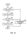
- FIG. 10 is a flowchart of a process performed by the radio terminal when restarting data communication.
- the base station 11 transmits a validity period to the radio terminal 12.
- the radio terminal 12 transmits a Connection Re-setup requesting to restart radio communication using RRC parameters used for the previous radio communication. Then, the base station 11 and the radio terminal 12 perform radio communication, using the RRC parameters used for the previous radio communication, without performing a process of exchanging RRC parameters.
- the base station 11 and the radio terminal 12 may handle NAS parameters in the same manner as RRC parameters described above.
- the base station 11 and the radio terminal 12 store NAS parameters together with RRC parameters in the storage units 21c and 31c, respectively, and use the previous NAS parameters for the current radio communication if the validity period has not expired. This allows the base station 11 and the radio terminal 12 to reduce the amount of signaling for setting up a NAS, and thus allows the radio terminal 12 to reduce power consumption, when restarting radio communication.
- the base station 11 and the radio terminal 12 retain RRC parameters in the storage units 21c and 31c, respectively, during the validity period. Accordingly, if the base station 11 needs to start radio communication with the radio terminal 12, the base station 11 may specify the radio terminal 12 using a C-RNTI contained in the RRC parameters and issue a request to start communication.
- the radio terminal 12 issues a communication request (performs a random access) to the base station 11 in step S13.
- the base station 11 may transmit a Msg0 to the radio terminal 12 before step S13 of FIG. 6 .
- the base station 11 may transmit a C-RNTI assigned to the radio terminal 12 in a Msg0 so as to specify the radio terminal 12 and start radio communication with the radio terminal 12.
- the radio terminal 12 Having received the Msg0 from the base station 11, the radio terminal 12 performs processing of step S13 and the subsequent steps of FIG. 6 . However, the processing of steps S15 and S16 are omitted. That is, if the communication control unit 31a of the radio terminal 12 receives a Msg0 from the base station 11 within the validity period, the communication control unit 31a does not transmit a Connection Re-setup to the base station 11. Further, if the communication control unit 21b of the base station 11 transmits a Msg0 to the radio terminal 12 within the validity period, the communication control unit 21b performs communication with the radio terminal 12 using RRC parameters, without receiving a Connection Re-Setup from the radio terminal 12.
- the base station 11 and the radio terminal 12 store RRC parameters in the storage units 21c and 31c, respectively, after completion of communication. Then, if the validity period has not expired, the base station 11 and the radio terminal 12 restart communication, using the RRC parameters stored in the storage units 21c and 31c, respectively.
- the content of the RRC parameters at the time of restarting communication may differ from the content of the RRC parameters at the time of the previous communication.
- the base station 11 transmits the difference, as difference information, to the radio terminal 12.
- the radio terminal 12 updates the RRC parameters stored in the storage unit 31c, based on the difference information received from the base station 11. Then, the base station 11 and the radio terminal 12 restart communication, based on the updated new RRC parameters.
- radio communication system of the third embodiment is the same as that of FIG. 2 , and hence a description thereof will be omitted.
- the base station 11 is the same as that illustrated in the block diagram of FIG. 4 , but the processing performed by the communication control unit 21b is different.
- the communication control unit 21b of the third embodiment compares RRC parameters for the current radio communication to be performed within the validity period and the RRC parameters used for the previous radio communication and stored in the storage unit 21c. Then, the communication control unit 21b extracts the difference in the RRC parameters, and transmits the difference, as difference information, to the radio terminal 12. That is, if a set of the RRC parameters used for the previous radio communication and a set of the RRC parameters to be used for the current radio communication differ from each other, the communication control unit 21b transmits to the radio terminal 12 information that differs between the two sets of RRC parameters.
- the communication control unit 21b transmits to the radio terminal 12 information indicating that there is no difference information. Further, if there is no difference information, the communication control unit 21b performs radio communication with the radio terminal 12, using the RRC parameters used for the previous radio communication and stored in the storage unit 21c.
- the radio terminal 12 is the same as that illustrated in the block diagram of FIG. 5 , but the processing performed by the communication control unit 31a is different.
- the communication control unit 31a of the third embodiment receives, as difference information, the difference of the RRC parameters for the current radio communication to be performed within the validity period from the RRC parameters used for the previous radio communication, from the base station 11.
- the communication control unit 31a updates the RRC parameters stored in the storage unit 31c with the received difference information so as to generate RRC parameters for the current radio communication. Note that if there is no difference information on the RRC parameters, the communication control unit 31a receives from the base station 11 information indicating that there is no difference information. In this case, the communication control unit 31a performs radio communication with the base station 11, using the RRC parameters stored in the storage unit 31c without making any change.
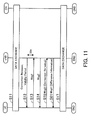
- FIG. 11 is a sequence diagram according to the third embodiment.
- the same steps as those of FIG. 6 are denoted by the same step numbers.
- the sequence of FIG. 11 differs from the sequence of FIG. 6 in the processing of step S16.
- the processing of steps S11 through S15 and S17 of FIG. 11 are the same as the processing of steps S11 through S15 and S17 of FIG. 6 , and a description thereof will be omitted.
- the communication control unit 31a of the radio terminal 12 updates the RRC parameters stored in the storage unit 31c with the received difference information so as to generate RRC parameters for the current radio communication (data exchange in step S17).
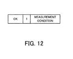
- FIG. 12 is a first diagram illustrating an example of difference information. More specifically, FIG. 12 illustrates an example of difference information transmitted from the base station 11 to the radio terminal 12. The difference information illustrated in FIG. 12 is transmitted from the base station 11 to the radio terminal 12 in a Msg4 (step S61 of FIG. 11 ).
- the RRC parameters include a C-RNTI and measurement information.
- the measurement information indicates the measurement conditions of the radio status of adjacent base stations, and is transmitted from the base station 11 to the radio terminal 12.
- the radio terminal 12 measures the radio status of the adjacent base stations in accordance with the received measurement information (measurement conditions), and transmits the measurement results to the base station 11.
- RRC parameters including a measurement condition 1, a measurement condition 2, and a measurement condition 3 are transmitted from the base station 11 to the radio terminal 12. Further, it is assumed that, for the current communication, the measurement condition 1 is changed.
- the communication control unit 21b of the base station 11 transmits to the radio terminal 12 a value "1" indicating the measurement condition 1 that is changed, and "measurement information” indicating the changed content.
- "OK” in FIG. 12 indicates the response to a Connection Re-setup (step S15 of FIG. 11 ) from the radio terminal 12.
- the communication control unit 31a of the radio terminal 12 changes the measurement condition 1 of the measurement information included in the RRC parameters stored in the storage unit 31c. That is, the communication control unit 31a changes the measurement condition 1 so as to reflect the content of the measurement condition indicated by the received difference information. Note that the communication control unit 31a does not change the other parameters of the RRC parameters.
- FIG. 13 is a second diagram illustrating an example of difference information. More specifically, FIG. 13 illustrates an example in the case where there is no difference information on the RRC parameters.
- the communication control unit 21b of the base station 11 transmits to the radio terminal 12 "OK" indicating the response to a Connection Re-setup and "0" indicating there is no change in the measurement conditions.
- the measurement conditions include the measurement condition 1, the measurement condition 2, and the measurement condition 3, for example. Accordingly, "0" of FIG. 13 indicates that there is no change in the measurement conditions.
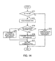
- FIG. 14 is a flowchart of a process performed by the base station when restarting data communication.
- the flowchart of a process performed by the base station when completing data communication is the same as the flowchart of FIG. 7 , and a description thereof will be omitted.
- Step S71 The communication control unit 21b determines whether a Connection Re-setup is received from the radio terminal 12. If the communication control unit 21b determines that a Connection Re-setup is not received, the process proceeds to step S72. If the communication control unit 21b determines that a Connection Re-setup is received, the process proceeds to step S73.
- the radio terminal 12 transmits a Connection Re-setup to the base station 11.
- the radio terminal 12 transmits a Connection Request to the base station 11.
- FIG. 15 is a flowchart of a process performed by the radio terminal when restarting data communication.
- the flowchart of a process performed by the radio terminal when completing data communication is the same as the flowchart of FIG. 9 , and a description thereof will be omitted.
- the communication control unit 31a determines whether there is difference information on the RRC parameters, based on the received Msg4. For example, if the information illustrated in FIG. 12 is received in a Msg4, the communication control unit 31a determines that there is difference information on the RRC parameters. If the information illustrated in FIG. 13 is received in a Msg4, the communication control unit 31a determines that there is no difference information on the RRC parameters.
- step S87 If the communication control unit 31a determines that there is difference information on the RRC parameters, the process proceeds to step S87. If there is no difference information on the RRC parameters, the communication control unit 31a performs data communication, using the RRC parameters stored in the storage unit 31c.
- the communication control unit 31a performs radio communication with the base station 11, using the updated RRC parameters.
- the base station 11 transmits the difference, as difference information, to the radio terminal 12.
- the radio terminal 12 updates the RRC parameters, based on the received difference information.
- the base station 11 and the radio terminal 12 are able to appropriately perform radio communication. Further, exchanging the difference information allows the base station 11 and the radio terminal 12 to reduce the amount of signaling, and thus allows the radio terminal 12 to reduce power consumption.
- FIG. 16 illustrates an example of the hardware configuration of the base station.
- the base station 11 includes a processor 41, a hard disk drive (HDD) 42, a random access memory (RAM) 43, a baseband unit 44, a radio-frequency unit 45, an interface unit 46, and a bus 47.
- a processor 41 a hard disk drive (HDD) 42, a random access memory (RAM) 43, a baseband unit 44, a radio-frequency unit 45, an interface unit 46, and a bus 47.
- HDD hard disk drive
- RAM random access memory
- the processor 41 is connected to the HDD 42, the RAM 43, the baseband unit 44, the radio-frequency unit 45, and the interface unit 46, via the bus 47.
- the entire operation of the base station 11 is controlled by the processor 41.
- Examples of the processor 41 include a central processing unit (CPU), a micro processing unit (MPU), and a digital signal processor (DSP).
- the HDD 42 stores an operating system (OS) program, a program for controlling the validity period of RRC parameters and for controlling communication, and a program defining the operation of the base station 11.
- the RAM 43 temporarily stores part of or all the data and programs used for various types of processing performed by the processor 41.
- the functions of the transmitting unit 1a and the communication unit 1b of FIG. 1 are realized by, for example, the processor 41. Further, the functions of the validity period calculation unit 21a and the communication control unit 21b of FIG. 4 are realized by, for example, the processor 41.
- the storage unit 21c is realized by, for example, the RAM 43.
- the baseband unit 44 performs baseband processing on data to be transmitted to the radio terminal 12 and data received from the radio terminal 12.
- the baseband unit 22 of FIG. 4 corresponds to the baseband unit 44.
- the radio-frequency unit 45 performs radio processing on data to be transmitted to the radio terminal 12 and data received from the radio terminal 12.
- the radio unit 23 of FIG. 4 corresponds to the radio-frequency unit 45.
- the interface unit 46 communicates with a core network apparatus as a host apparatus or a server in a core network through, for example, wires.
- the hardware configuration of the radio terminal 12 is the same as that of FIG. 16 , except that the radio terminal 12 does not have the interface unit 46.
- the HDD 42 may be a flash memory.
- the functions of the receiving unit 2a and the communication unit 2b of FIG. 1 are realized by, for example, the processor 41.
- the functions of the communication control unit 31a of FIG. 5 are realized by, for example, the processor 41.
- the functions of the validity period timer 31b are realized by, for example, a timer that is not illustrated in FIG. 16 .
- the storage unit 31c is realized by, for example, the RAM 43.
Landscapes
- Engineering & Computer Science (AREA)
- Computer Networks & Wireless Communication (AREA)
- Signal Processing (AREA)
- Mobile Radio Communication Systems (AREA)
Applications Claiming Priority (1)
| Application Number | Priority Date | Filing Date | Title |
|---|---|---|---|
| PCT/JP2012/050148 WO2013103010A1 (ja) | 2012-01-06 | 2012-01-06 | 基地局、無線端末、無線通信システム、および無線通信方法 |
Publications (3)
| Publication Number | Publication Date |
|---|---|
| EP2802177A1 true EP2802177A1 (de) | 2014-11-12 |
| EP2802177A4 EP2802177A4 (de) | 2016-01-27 |
| EP2802177B1 EP2802177B1 (de) | 2019-05-22 |
Family
ID=48745080
Family Applications (1)
| Application Number | Title | Priority Date | Filing Date |
|---|---|---|---|
| EP12864614.8A Active EP2802177B1 (de) | 2012-01-06 | 2012-01-06 | Basisstation, drahtloses endgerät, drahtloses kommunikationssystem und drahtloses kommunikationsverfahren |
Country Status (6)
| Country | Link |
|---|---|
| US (1) | US9451544B2 (de) |
| EP (1) | EP2802177B1 (de) |
| JP (1) | JP5768899B2 (de) |
| KR (1) | KR101604937B1 (de) |
| CN (1) | CN104025670B (de) |
| WO (1) | WO2013103010A1 (de) |
Cited By (2)
| Publication number | Priority date | Publication date | Assignee | Title |
|---|---|---|---|---|
| WO2023215146A1 (en) * | 2022-05-03 | 2023-11-09 | Arris Enterprises Llc | Association and re-association request device steering utilizing controller direction |
| US11877500B2 (en) | 2020-06-15 | 2024-01-16 | Samsung Display Co., Ltd. | Mask assembly |
Families Citing this family (8)
| Publication number | Priority date | Publication date | Assignee | Title |
|---|---|---|---|---|
| JP5943075B2 (ja) * | 2012-06-20 | 2016-06-29 | 富士通株式会社 | 無線通信システム、無線局、基地局および通信方法 |
| JP5844441B1 (ja) * | 2014-08-08 | 2016-01-20 | ソフトバンク株式会社 | 通信端末装置及び通信システム |
| KR102000508B1 (ko) | 2015-05-06 | 2019-10-04 | 텔레폰악티에볼라겟엘엠에릭슨(펍) | 무선 통신 네트워크에서 라디오 액세스 네트워크(ran)의 콘텍스트를 처리하기 위한 네트워크 노드, 무선 장치 및 방법 |
| EP3373653B1 (de) * | 2015-11-26 | 2021-12-22 | Huawei Technologies Co., Ltd. | Verfahren, endgerät und zugangsnetzknoten zur rrc-verbindungsverwaltung |
| WO2017200481A1 (en) | 2016-05-20 | 2017-11-23 | Telefonaktiebolaget Lm Ericsson (Publ) | Methods and apparatuses for storage of ue contexts in a radio access network for inactive user equipments |
| CN114466327B (zh) | 2016-09-30 | 2025-08-19 | Kddi株式会社 | 通信终端、通信方法、通信用程序、通信系统、管理装置、管理方法及通信控制方法 |
| JP6450719B2 (ja) * | 2016-09-30 | 2019-01-09 | Kddi株式会社 | 通信システム、通信端末及び通信制御方法 |
| CN116325818B (zh) * | 2020-11-12 | 2026-01-09 | 华为技术有限公司 | 一种通信方法及装置 |
Family Cites Families (20)
| Publication number | Priority date | Publication date | Assignee | Title |
|---|---|---|---|---|
| US7406065B2 (en) | 2002-03-14 | 2008-07-29 | Qualcomm, Incorporated | Method and apparatus for reducing inter-channel interference in a wireless communication system |
| US7292552B2 (en) | 2002-03-14 | 2007-11-06 | Qualcomm Incorporated | Method and apparatus for reducing interference in a wireless communication system |
| JP2006086718A (ja) * | 2004-09-15 | 2006-03-30 | Fujitsu Ltd | アクセスルータ及び端末装置 |
| CN101060712B (zh) * | 2006-04-20 | 2011-08-24 | 华为技术有限公司 | 无线连接建立方法 |
| PL2044796T3 (pl) * | 2006-09-21 | 2010-11-30 | Intel Mobile Communications Gmb | Grupowanie inforamacji o dostępie urządzenia końcowego abonenta do komórki w jednym bloku informacyjnym informacji systemowych |
| KR100948550B1 (ko) * | 2006-10-20 | 2010-03-18 | 삼성전자주식회사 | 다중홉 릴레이 방식을 사용하는 광대역 무선접속시스템에서 제어정보 통신 장치 및 방법 |
| JP4880496B2 (ja) * | 2007-02-23 | 2012-02-22 | 京セラ株式会社 | 無線通信システム、無線通信端末、無線基地局及び無線通信方法 |
| EP2139259B1 (de) * | 2007-03-23 | 2012-04-25 | NTT DoCoMo, Inc. | Übertragungsneustartverfahren, mobilstation und drahtlose basisstation |
| JP2008306384A (ja) | 2007-06-06 | 2008-12-18 | Mitsubishi Electric Corp | 通信方法および通信システム |
| RU2471312C2 (ru) | 2007-08-17 | 2012-12-27 | Нтт Досомо, Инк. | Терминал пользователя и система радиосвязи |
| JP5144314B2 (ja) * | 2008-03-11 | 2013-02-13 | 株式会社日立国際電気 | 同報無線システム |
| EP2413657B1 (de) * | 2008-04-28 | 2016-04-20 | Fujitsu Limited | Re-établissement de liaison après un rejet d'établissement de liaison |
| CN102017715B (zh) * | 2008-05-09 | 2014-09-24 | 西门子企业通讯有限责任两合公司 | 用于为无线网状网络创建分配消息的至少一个扩展的方法和装置 |
| US8289891B2 (en) | 2008-05-09 | 2012-10-16 | Samsung Electronics Co., Ltd. | Flexible sleep mode for advanced wireless systems |
| KR101240138B1 (ko) * | 2008-06-02 | 2013-03-11 | 후지쯔 가부시끼가이샤 | 상향 송신 제어 방법, 이동국, 기지국 및 이동 통신 시스템 |
| KR101528856B1 (ko) * | 2008-08-14 | 2015-06-15 | 삼성전자주식회사 | 애플리케이션 제어 정보를 획득하는 컨텐츠 수신 장치 및 그 방법 |
| JP5538802B2 (ja) | 2008-11-04 | 2014-07-02 | 三菱電機株式会社 | 通信方法、移動体通信システム、移動端末および基地局制御装置 |
| KR101485987B1 (ko) * | 2009-03-13 | 2015-01-23 | 닛본 덴끼 가부시끼가이샤 | 무선 통신 시스템과 방법과 무선 기지국과 제어국 |
| US9161381B2 (en) * | 2010-01-13 | 2015-10-13 | Lg Electronics Inc. | Communication method in a mobile communication system using MTC equipment, and device for same |
| JP5545368B2 (ja) | 2010-06-18 | 2014-07-09 | 富士通株式会社 | 無線通信方法、無線通信装置および無線通信システム |
-
2012
- 2012-01-06 WO PCT/JP2012/050148 patent/WO2013103010A1/ja not_active Ceased
- 2012-01-06 CN CN201280065479.6A patent/CN104025670B/zh not_active Expired - Fee Related
- 2012-01-06 JP JP2013552372A patent/JP5768899B2/ja not_active Expired - Fee Related
- 2012-01-06 EP EP12864614.8A patent/EP2802177B1/de active Active
- 2012-01-06 KR KR1020147018331A patent/KR101604937B1/ko not_active Expired - Fee Related
-
2014
- 2014-07-01 US US14/321,345 patent/US9451544B2/en active Active
Cited By (3)
| Publication number | Priority date | Publication date | Assignee | Title |
|---|---|---|---|---|
| US11877500B2 (en) | 2020-06-15 | 2024-01-16 | Samsung Display Co., Ltd. | Mask assembly |
| WO2023215146A1 (en) * | 2022-05-03 | 2023-11-09 | Arris Enterprises Llc | Association and re-association request device steering utilizing controller direction |
| US12557011B2 (en) | 2022-05-03 | 2026-02-17 | Ruckus Ip Holdings Llc | Association and re-association request station steering utilizing controller direction |
Also Published As
| Publication number | Publication date |
|---|---|
| EP2802177B1 (de) | 2019-05-22 |
| US9451544B2 (en) | 2016-09-20 |
| WO2013103010A1 (ja) | 2013-07-11 |
| JP5768899B2 (ja) | 2015-08-26 |
| KR101604937B1 (ko) | 2016-03-18 |
| CN104025670A (zh) | 2014-09-03 |
| JPWO2013103010A1 (ja) | 2015-05-11 |
| EP2802177A4 (de) | 2016-01-27 |
| KR20140097556A (ko) | 2014-08-06 |
| US20140313978A1 (en) | 2014-10-23 |
| CN104025670B (zh) | 2018-04-27 |
Similar Documents
| Publication | Publication Date | Title |
|---|---|---|
| EP2802177B1 (de) | Basisstation, drahtloses endgerät, drahtloses kommunikationssystem und drahtloses kommunikationsverfahren | |
| KR102733153B1 (ko) | 무선 단말, 무선 액세스 네트워크 노드, 및 이들의 방법 | |
| CN113163430B (zh) | 用于蜂窝通信网络中的休眠带宽部分的波束故障检测 | |
| EP3068175B1 (de) | Vorrichtung und netzwerk zur handhabung von energieeinsparung | |
| RU2750786C1 (ru) | Способ поискового вызова, оконечное устройство и сетевое устройство | |
| KR102240644B1 (ko) | 데이터 전송/수신 장치 및 방법, 및 통신 시스템 | |
| CN111586852B (zh) | 一种通信方法及装置 | |
| US20240373497A1 (en) | Methods and apparatuses for data and signaling transmission | |
| US11228975B2 (en) | Service control apparatus, charging management server, service control method, charging information management method, and computer readable medium | |
| WO2015109695A1 (zh) | Mtc用户设备的节能方法及系统、用户设备、rnc | |
| CN111108785B (zh) | 用于无线网络的网络切片特定寻呼周期 | |
| US12439472B2 (en) | Receiving data without monitoring control channel | |
| CN110062394B (zh) | 更新系统消息的方法及装置 | |
| JPWO2021189462A5 (de) | ||
| CN115004801B (zh) | 一种通信方法及装置 | |
| CN103582035B (zh) | 一种无线资源配置的管理方法和系统 | |
| CN116506864A (zh) | 通信方法及装置 | |
| JP2016021630A (ja) | ユーザ装置及びセル検索方法 | |
| CN113302965A (zh) | 无线通信的方法和无线通信装置 | |
| JP7712474B2 (ja) | 小規模データ送信のための通信 | |
| EP4391670A1 (de) | Temporäre tracking-bereichsunterstützung | |
| CN118524508A (zh) | 定时相关状态更新 | |
| CN118743276A (zh) | 蜂窝通信网络中的小数据传输期间的测量 | |
| CN119064970A (zh) | Gnss定位测量方法及装置、终端设备 | |
| CN117835173A (zh) | 语音呼叫方法、通信装置及计算机可读存储介质 |
Legal Events
| Date | Code | Title | Description |
|---|---|---|---|
| PUAI | Public reference made under article 153(3) epc to a published international application that has entered the european phase |
Free format text: ORIGINAL CODE: 0009012 |
|
| 17P | Request for examination filed |
Effective date: 20140707 |
|
| AK | Designated contracting states |
Kind code of ref document: A1 Designated state(s): AL AT BE BG CH CY CZ DE DK EE ES FI FR GB GR HR HU IE IS IT LI LT LU LV MC MK MT NL NO PL PT RO RS SE SI SK SM TR |
|
| DAX | Request for extension of the european patent (deleted) | ||
| RA4 | Supplementary search report drawn up and despatched (corrected) |
Effective date: 20160108 |
|
| RIC1 | Information provided on ipc code assigned before grant |
Ipc: H04W 52/02 20090101AFI20151223BHEP Ipc: H04W 76/04 20090101ALI20151223BHEP Ipc: H04W 48/08 20090101ALN20151223BHEP Ipc: H04W 76/06 20090101ALN20151223BHEP Ipc: H04W 76/02 20090101ALN20151223BHEP Ipc: H04W 48/10 20090101ALN20151223BHEP |
|
| GRAP | Despatch of communication of intention to grant a patent |
Free format text: ORIGINAL CODE: EPIDOSNIGR1 |
|
| STAA | Information on the status of an ep patent application or granted ep patent |
Free format text: STATUS: GRANT OF PATENT IS INTENDED |
|
| RIC1 | Information provided on ipc code assigned before grant |
Ipc: H04W 48/10 20090101ALN20181128BHEP Ipc: H04W 76/25 20180101ALI20181128BHEP Ipc: H04W 48/08 20090101ALN20181128BHEP Ipc: H04W 52/02 20090101AFI20181128BHEP |
|
| INTG | Intention to grant announced |
Effective date: 20181221 |
|
| RIN1 | Information on inventor provided before grant (corrected) |
Inventor name: SUGIYAMA, KATSUMASA Inventor name: ITO, AKIRA Inventor name: OHTA, YOSHIAKI Inventor name: TAJIMA, YOSHIHARU |
|
| RIC1 | Information provided on ipc code assigned before grant |
Ipc: H04W 52/02 20090101AFI20181128BHEP Ipc: H04W 48/08 20090101ALN20181128BHEP Ipc: H04W 76/25 20180101ALI20181128BHEP Ipc: H04W 48/10 20090101ALN20181128BHEP |
|
| GRAS | Grant fee paid |
Free format text: ORIGINAL CODE: EPIDOSNIGR3 |
|
| GRAA | (expected) grant |
Free format text: ORIGINAL CODE: 0009210 |
|
| STAA | Information on the status of an ep patent application or granted ep patent |
Free format text: STATUS: THE PATENT HAS BEEN GRANTED |
|
| AK | Designated contracting states |
Kind code of ref document: B1 Designated state(s): AL AT BE BG CH CY CZ DE DK EE ES FI FR GB GR HR HU IE IS IT LI LT LU LV MC MK MT NL NO PL PT RO RS SE SI SK SM TR |
|
| REG | Reference to a national code |
Ref country code: GB Ref legal event code: FG4D |
|
| REG | Reference to a national code |
Ref country code: CH Ref legal event code: EP |
|
| REG | Reference to a national code |
Ref country code: IE Ref legal event code: FG4D |
|
| REG | Reference to a national code |
Ref country code: AT Ref legal event code: REF Ref document number: 1137625 Country of ref document: AT Kind code of ref document: T Effective date: 20190615 |
|
| REG | Reference to a national code |
Ref country code: DE Ref legal event code: R096 Ref document number: 602012060492 Country of ref document: DE |
|
| REG | Reference to a national code |
Ref country code: NL Ref legal event code: MP Effective date: 20190522 |
|
| REG | Reference to a national code |
Ref country code: LT Ref legal event code: MG4D |
|
| PG25 | Lapsed in a contracting state [announced via postgrant information from national office to epo] |
Ref country code: AL Free format text: LAPSE BECAUSE OF FAILURE TO SUBMIT A TRANSLATION OF THE DESCRIPTION OR TO PAY THE FEE WITHIN THE PRESCRIBED TIME-LIMIT Effective date: 20190522 Ref country code: PT Free format text: LAPSE BECAUSE OF FAILURE TO SUBMIT A TRANSLATION OF THE DESCRIPTION OR TO PAY THE FEE WITHIN THE PRESCRIBED TIME-LIMIT Effective date: 20190922 Ref country code: SE Free format text: LAPSE BECAUSE OF FAILURE TO SUBMIT A TRANSLATION OF THE DESCRIPTION OR TO PAY THE FEE WITHIN THE PRESCRIBED TIME-LIMIT Effective date: 20190522 Ref country code: FI Free format text: LAPSE BECAUSE OF FAILURE TO SUBMIT A TRANSLATION OF THE DESCRIPTION OR TO PAY THE FEE WITHIN THE PRESCRIBED TIME-LIMIT Effective date: 20190522 Ref country code: NO Free format text: LAPSE BECAUSE OF FAILURE TO SUBMIT A TRANSLATION OF THE DESCRIPTION OR TO PAY THE FEE WITHIN THE PRESCRIBED TIME-LIMIT Effective date: 20190822 Ref country code: HR Free format text: LAPSE BECAUSE OF FAILURE TO SUBMIT A TRANSLATION OF THE DESCRIPTION OR TO PAY THE FEE WITHIN THE PRESCRIBED TIME-LIMIT Effective date: 20190522 Ref country code: NL Free format text: LAPSE BECAUSE OF FAILURE TO SUBMIT A TRANSLATION OF THE DESCRIPTION OR TO PAY THE FEE WITHIN THE PRESCRIBED TIME-LIMIT Effective date: 20190522 Ref country code: LT Free format text: LAPSE BECAUSE OF FAILURE TO SUBMIT A TRANSLATION OF THE DESCRIPTION OR TO PAY THE FEE WITHIN THE PRESCRIBED TIME-LIMIT Effective date: 20190522 Ref country code: ES Free format text: LAPSE BECAUSE OF FAILURE TO SUBMIT A TRANSLATION OF THE DESCRIPTION OR TO PAY THE FEE WITHIN THE PRESCRIBED TIME-LIMIT Effective date: 20190522 |
|
| PG25 | Lapsed in a contracting state [announced via postgrant information from national office to epo] |
Ref country code: LV Free format text: LAPSE BECAUSE OF FAILURE TO SUBMIT A TRANSLATION OF THE DESCRIPTION OR TO PAY THE FEE WITHIN THE PRESCRIBED TIME-LIMIT Effective date: 20190522 Ref country code: RS Free format text: LAPSE BECAUSE OF FAILURE TO SUBMIT A TRANSLATION OF THE DESCRIPTION OR TO PAY THE FEE WITHIN THE PRESCRIBED TIME-LIMIT Effective date: 20190522 Ref country code: BG Free format text: LAPSE BECAUSE OF FAILURE TO SUBMIT A TRANSLATION OF THE DESCRIPTION OR TO PAY THE FEE WITHIN THE PRESCRIBED TIME-LIMIT Effective date: 20190822 Ref country code: GR Free format text: LAPSE BECAUSE OF FAILURE TO SUBMIT A TRANSLATION OF THE DESCRIPTION OR TO PAY THE FEE WITHIN THE PRESCRIBED TIME-LIMIT Effective date: 20190823 |
|
| REG | Reference to a national code |
Ref country code: AT Ref legal event code: MK05 Ref document number: 1137625 Country of ref document: AT Kind code of ref document: T Effective date: 20190522 |
|
| PG25 | Lapsed in a contracting state [announced via postgrant information from national office to epo] |
Ref country code: CZ Free format text: LAPSE BECAUSE OF FAILURE TO SUBMIT A TRANSLATION OF THE DESCRIPTION OR TO PAY THE FEE WITHIN THE PRESCRIBED TIME-LIMIT Effective date: 20190522 Ref country code: AT Free format text: LAPSE BECAUSE OF FAILURE TO SUBMIT A TRANSLATION OF THE DESCRIPTION OR TO PAY THE FEE WITHIN THE PRESCRIBED TIME-LIMIT Effective date: 20190522 Ref country code: RO Free format text: LAPSE BECAUSE OF FAILURE TO SUBMIT A TRANSLATION OF THE DESCRIPTION OR TO PAY THE FEE WITHIN THE PRESCRIBED TIME-LIMIT Effective date: 20190522 Ref country code: DK Free format text: LAPSE BECAUSE OF FAILURE TO SUBMIT A TRANSLATION OF THE DESCRIPTION OR TO PAY THE FEE WITHIN THE PRESCRIBED TIME-LIMIT Effective date: 20190522 Ref country code: EE Free format text: LAPSE BECAUSE OF FAILURE TO SUBMIT A TRANSLATION OF THE DESCRIPTION OR TO PAY THE FEE WITHIN THE PRESCRIBED TIME-LIMIT Effective date: 20190522 Ref country code: SK Free format text: LAPSE BECAUSE OF FAILURE TO SUBMIT A TRANSLATION OF THE DESCRIPTION OR TO PAY THE FEE WITHIN THE PRESCRIBED TIME-LIMIT Effective date: 20190522 |
|
| REG | Reference to a national code |
Ref country code: DE Ref legal event code: R097 Ref document number: 602012060492 Country of ref document: DE |
|
| PG25 | Lapsed in a contracting state [announced via postgrant information from national office to epo] |
Ref country code: SM Free format text: LAPSE BECAUSE OF FAILURE TO SUBMIT A TRANSLATION OF THE DESCRIPTION OR TO PAY THE FEE WITHIN THE PRESCRIBED TIME-LIMIT Effective date: 20190522 |
|
| PLBE | No opposition filed within time limit |
Free format text: ORIGINAL CODE: 0009261 |
|
| STAA | Information on the status of an ep patent application or granted ep patent |
Free format text: STATUS: NO OPPOSITION FILED WITHIN TIME LIMIT |
|
| PG25 | Lapsed in a contracting state [announced via postgrant information from national office to epo] |
Ref country code: TR Free format text: LAPSE BECAUSE OF FAILURE TO SUBMIT A TRANSLATION OF THE DESCRIPTION OR TO PAY THE FEE WITHIN THE PRESCRIBED TIME-LIMIT Effective date: 20190522 |
|
| 26N | No opposition filed |
Effective date: 20200225 |
|
| PG25 | Lapsed in a contracting state [announced via postgrant information from national office to epo] |
Ref country code: PL Free format text: LAPSE BECAUSE OF FAILURE TO SUBMIT A TRANSLATION OF THE DESCRIPTION OR TO PAY THE FEE WITHIN THE PRESCRIBED TIME-LIMIT Effective date: 20190522 |
|
| PG25 | Lapsed in a contracting state [announced via postgrant information from national office to epo] |
Ref country code: SI Free format text: LAPSE BECAUSE OF FAILURE TO SUBMIT A TRANSLATION OF THE DESCRIPTION OR TO PAY THE FEE WITHIN THE PRESCRIBED TIME-LIMIT Effective date: 20190522 |
|
| PG25 | Lapsed in a contracting state [announced via postgrant information from national office to epo] |
Ref country code: MC Free format text: LAPSE BECAUSE OF FAILURE TO SUBMIT A TRANSLATION OF THE DESCRIPTION OR TO PAY THE FEE WITHIN THE PRESCRIBED TIME-LIMIT Effective date: 20190522 |
|
| REG | Reference to a national code |
Ref country code: CH Ref legal event code: PL |
|
| REG | Reference to a national code |
Ref country code: BE Ref legal event code: MM Effective date: 20200131 |
|
| PG25 | Lapsed in a contracting state [announced via postgrant information from national office to epo] |
Ref country code: LU Free format text: LAPSE BECAUSE OF NON-PAYMENT OF DUE FEES Effective date: 20200106 |
|
| PG25 | Lapsed in a contracting state [announced via postgrant information from national office to epo] |
Ref country code: CH Free format text: LAPSE BECAUSE OF NON-PAYMENT OF DUE FEES Effective date: 20200131 Ref country code: BE Free format text: LAPSE BECAUSE OF NON-PAYMENT OF DUE FEES Effective date: 20200131 Ref country code: LI Free format text: LAPSE BECAUSE OF NON-PAYMENT OF DUE FEES Effective date: 20200131 |
|
| REG | Reference to a national code |
Ref country code: DE Ref legal event code: R082 Ref document number: 602012060492 Country of ref document: DE Representative=s name: HL KEMPNER PATENTANWAELTE, SOLICITORS (ENGLAND, DE Ref country code: DE Ref legal event code: R082 Ref document number: 602012060492 Country of ref document: DE Representative=s name: HL KEMPNER PATENTANWALT, RECHTSANWALT, SOLICIT, DE |
|
| PG25 | Lapsed in a contracting state [announced via postgrant information from national office to epo] |
Ref country code: IE Free format text: LAPSE BECAUSE OF NON-PAYMENT OF DUE FEES Effective date: 20200106 |
|
| PG25 | Lapsed in a contracting state [announced via postgrant information from national office to epo] |
Ref country code: MT Free format text: LAPSE BECAUSE OF FAILURE TO SUBMIT A TRANSLATION OF THE DESCRIPTION OR TO PAY THE FEE WITHIN THE PRESCRIBED TIME-LIMIT Effective date: 20190522 Ref country code: CY Free format text: LAPSE BECAUSE OF FAILURE TO SUBMIT A TRANSLATION OF THE DESCRIPTION OR TO PAY THE FEE WITHIN THE PRESCRIBED TIME-LIMIT Effective date: 20190522 |
|
| PG25 | Lapsed in a contracting state [announced via postgrant information from national office to epo] |
Ref country code: MK Free format text: LAPSE BECAUSE OF FAILURE TO SUBMIT A TRANSLATION OF THE DESCRIPTION OR TO PAY THE FEE WITHIN THE PRESCRIBED TIME-LIMIT Effective date: 20190522 Ref country code: IS Free format text: LAPSE BECAUSE OF FAILURE TO SUBMIT A TRANSLATION OF THE DESCRIPTION OR TO PAY THE FEE WITHIN THE PRESCRIBED TIME-LIMIT Effective date: 20190922 |
|
| PGFP | Annual fee paid to national office [announced via postgrant information from national office to epo] |
Ref country code: GB Payment date: 20221201 Year of fee payment: 12 Ref country code: FR Payment date: 20221208 Year of fee payment: 12 |
|
| PGFP | Annual fee paid to national office [announced via postgrant information from national office to epo] |
Ref country code: IT Payment date: 20221213 Year of fee payment: 12 Ref country code: DE Payment date: 20221130 Year of fee payment: 12 |
|
| REG | Reference to a national code |
Ref country code: DE Ref legal event code: R119 Ref document number: 602012060492 Country of ref document: DE |
|
| GBPC | Gb: european patent ceased through non-payment of renewal fee |
Effective date: 20240106 |
|
| PG25 | Lapsed in a contracting state [announced via postgrant information from national office to epo] |
Ref country code: DE Free format text: LAPSE BECAUSE OF NON-PAYMENT OF DUE FEES Effective date: 20240801 |
|
| PG25 | Lapsed in a contracting state [announced via postgrant information from national office to epo] |
Ref country code: GB Free format text: LAPSE BECAUSE OF NON-PAYMENT OF DUE FEES Effective date: 20240106 |
|
| PG25 | Lapsed in a contracting state [announced via postgrant information from national office to epo] |
Ref country code: FR Free format text: LAPSE BECAUSE OF NON-PAYMENT OF DUE FEES Effective date: 20240131 |
|
| PG25 | Lapsed in a contracting state [announced via postgrant information from national office to epo] |
Ref country code: GB Free format text: LAPSE BECAUSE OF NON-PAYMENT OF DUE FEES Effective date: 20240106 Ref country code: FR Free format text: LAPSE BECAUSE OF NON-PAYMENT OF DUE FEES Effective date: 20240131 Ref country code: DE Free format text: LAPSE BECAUSE OF NON-PAYMENT OF DUE FEES Effective date: 20240801 |
|
| PG25 | Lapsed in a contracting state [announced via postgrant information from national office to epo] |
Ref country code: IT Free format text: LAPSE BECAUSE OF NON-PAYMENT OF DUE FEES Effective date: 20240106 |