EP2802182A1 - Verfahren zur Einplanung von Benutzerendgeräten auf Ressourcen sowie Basisstation dafür - Google Patents
Verfahren zur Einplanung von Benutzerendgeräten auf Ressourcen sowie Basisstation dafür Download PDFInfo
- Publication number
- EP2802182A1 EP2802182A1 EP13305589.7A EP13305589A EP2802182A1 EP 2802182 A1 EP2802182 A1 EP 2802182A1 EP 13305589 A EP13305589 A EP 13305589A EP 2802182 A1 EP2802182 A1 EP 2802182A1
- Authority
- EP
- European Patent Office
- Prior art keywords
- user terminals
- resources
- resource
- scheduling
- scheduled
- Prior art date
- Legal status (The legal status is an assumption and is not a legal conclusion. Google has not performed a legal analysis and makes no representation as to the accuracy of the status listed.)
- Withdrawn
Links
Images



Classifications
-
- H—ELECTRICITY
- H04—ELECTRIC COMMUNICATION TECHNIQUE
- H04W—WIRELESS COMMUNICATION NETWORKS
- H04W72/00—Local resource management
- H04W72/50—Allocation or scheduling criteria for wireless resources
- H04W72/54—Allocation or scheduling criteria for wireless resources based on quality criteria
- H04W72/543—Allocation or scheduling criteria for wireless resources based on quality criteria based on requested quality, e.g. QoS
-
- H—ELECTRICITY
- H04—ELECTRIC COMMUNICATION TECHNIQUE
- H04W—WIRELESS COMMUNICATION NETWORKS
- H04W72/00—Local resource management
- H04W72/50—Allocation or scheduling criteria for wireless resources
- H04W72/56—Allocation or scheduling criteria for wireless resources based on priority criteria
- H04W72/566—Allocation or scheduling criteria for wireless resources based on priority criteria of the information or information source or recipient
Definitions
- the invention relates to a method for scheduling of user terminals to resources, and a base station adapted to perform said method.
- Frequency Selective Scheduling the user terminals provide frequency selective channel feedback. This enables the scheduler to exploit frequency and user diversity by assigning resources to the user terminals which are best suited for these resources. Therefore Frequency Selective Scheduling leads, compared to Round-Robin scheduling, to an increased system performance.
- Frequency Selective Scheduling shares the available resources among a relatively high fraction of the available user terminals.
- a high number of allocations per subframe, i.e. scheduled user terminals per subframe, leads to a high signaling overhead, because each allocation has to be signaled on the so-called Physical Downlink Control Channel (PDCCH). Therefore the PDCCH has to be dimensioned in a way that it can carry this high signaling load.
- PDCCH Physical Downlink Control Channel
- the number of allocations per subframe leads to an increase in the spectral efficiency until the number of allocations reaches a certain value from which on the spectral efficiency goes into saturation. So, the number of allocations per subframe can be reduced to said certain value, i.e. maximum number of allocations, without significant performance loss, which in turn leads to a much lower load on the PDCCH.
- a smaller dimensioning of the PDCCH is possible, which would lead to more user data capacity because the symbol which is not needed for PDCCH can be used for the so-called Physical Downlink Shared Channel (PDSCH).
- PDSCH Physical Downlink Shared Channel
- LTE enables to apply user specific aggregation levels for the signaling messages on the PDCCH. Therefore the required PDCCH capacity for signaling a certain number of allocations not only depends on the number of allocations, i.e. the number of scheduled user terminals, but also on the current channel conditions of the scheduled user terminals. Therefore, fixed configured values for the PDCCH dimensioning and the maximum number of allocations are not suitable to maximize the system performance. Instead optimal values for both parameters have to be dynamically adapted or determined.
- the object of the invention is thus to propose a method for scheduling of user terminals to resources which leads to a high overall data throughput of the scheduled user terminals.
- a basic idea of the invention is to dynamically co-optimize scheduling, i.e. selecting an appropriate number of allocations, and PDCCH dimensioning. Based on the current radio condition and data throughput, an appropriate value for both parameters number of allocations and PDCCH dimensioning will be determined preferably on a subframe basis.
- a scheduler is assumed that calculates resource scheduling priorities for user terminals based e.g. on an expected data throughput for a considered resource and on an average data throughput.
- the total priority of a user terminal i.e. the sum of all its resource scheduling priorities serves for determining the set of scheduled user terminals to be served during a subframe.
- the expected data throughput per user terminal and per resource which can be deduced from frequency selective feedback, is exploited for determining the best PDCCH configuration, i.e. the one with the highest sum capacity or overall data throughput.
- the object of the invention is thus achieved by a method for scheduling of user terminals to resources, wherein
- the object of the invention is furthermore achieved by a base station for scheduling of user terminals to resources, wherein said base station is adapted to
- WiMAX Worldwide Interoperability for Microwave Access
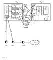
- Fig. 1 shows as an example of a communication network in which the invention can be implemented a communication network CN according to the standard 3GPP LTE.
- Said communication network CN comprises base stations BS1-BS3, user terminals UE11-UE31, a serving gateway SGW, a packet data network gateway PDNGW, and a mobility management entity MME.
- the user terminals UE11-UE15 are connected via radio connections to the base station BS1, the user terminals UE21-UE23 are connected via radio connections to the base station BS2, and the user terminal UE31 is connected via a radio connection to the base station BS3.
- each of the user terminals UE11-UE31 can also be connected via radio connections to multiple of said base stations BS1-BS3.
- the base stations BS1-BS3 are in turn connected to the serving gateway SGW and to the mobility management entity MME, i.e. to the evolved packet core (EPC), via the so-called S1 interface.
- EPC evolved packet core
- the base stations BS1-BS3 are connected among each other via the so-called X2 interface.
- the serving gateway SGW is connected to the packet data network gateway PDNGW, which is in turn connected to an external IP network IPN.
- the S1 interface is a standardized interface between one of the base stations BS1-BS3, i.e. an eNodeB in this example, and the Evolved Packet Core (EPC).
- the S1 interface has two flavours, S1-MME for exchange of signaling messages between one of the base stations BS1-BS3 and the mobility management entity MME and S1-U for the transport of user datagrams between one of the base stations BS1-BS3 and the serving gateway SGW.
- the X2 interface is added in 3GPP LTE standard primarily in order to transfer the user plane signal and the control plane signal during handover.
- the serving gateway SGW performs routing of the IP user data between the base stations BS1-BS3, and the packet data network gateway PDNGW. Furthermore, the serving gateway SGW serves as a mobile anchor point during handover either between different base stations, or between different 3GPP access networks.
- EPS Evolved Packet System
- the mobility management entity MME performs tasks of the subscriber management and the session management, and also performs the mobility management during handover between different access networks.
- Fig. 2 schematically shows the structure of a user terminal UE and a base station BS in which the invention can be implemented.
- the base station BS comprises by way of example three modem unit boards MU1-MU3 and a control unit board CU1, which in turn comprises a media dependent adapter MDA.
- the three modem unit boards MU1-MU3 are connected to the control unit board CU1, and to a respective remote radio head RRH1, RRH2, or RRH3 via a so-called Common Public Radio Interface (CPRI).
- CPRI Common Public Radio Interface
- Each of the remote radio heads RRH1, RRH2, and RRH3 is connected by way of example to two remote radio head antennas RRHA1 and RRHA2 for transmission and reception of data via a radio interface. Said two remote radio head antennas RRHA1 and RRHA2 are only depicted for the remote radio head RRH1 in fig. 2 for the sake of simplicity.
- the media dependent adapter MDA is connected to the mobility management entity MME and to the serving gateway SGW and thus to the packet data network gateway PDNGW, which is in turn connected to the external IP network IPN.
- the user terminal UE comprises by way of example two user terminal antennas UEA1 and UEA2, a modem unit board MU4, a control unit board CU2, and interfaces INT.
- the two user terminal antennas UEA1 and UEA2 are connected to the modem unit board MU4.
- the modem unit board MU4 is connected to the control unit board CU2, which is in turn connected to interfaces INT.
- the modem unit boards MU1-MU4 and the control unit boards CU1, CU2 may comprise by way of example Field Programmable Gate Arrays (FPGA), Digital Signal Processors (DSP), micro processors, switches and memories, like e.g. Double Data Rate Synchronous Dynamic Random Access Memories (DDR-SDRAM) in order to be enabled to perform the tasks described below.
- FPGA Field Programmable Gate Arrays
- DSP Digital Signal Processors
- DDR-SDRAM Double Data Rate Synchronous Dynamic Random Access Memories
- the remote radio heads RRH1, RRH2, and RRH3 comprise the so-called radio equipment, e.g. modulators and amplifiers, like delta-sigma modulators (DSM) and switch mode amplifiers.
- modulators and amplifiers like delta-sigma modulators (DSM) and switch mode amplifiers.
- IP data received from the external IP network IPN are transmitted from the packet data network gateway PDNGW via the serving gateway SGW to the media dependent adapter MDA of the base station BS on an EPS bearer.
- the media dependent adapter MDA allows for a connectivity to different media like e.g. fiber or electrical connection.
- the control unit board CU1 performs tasks on layer 3, i.e. on the radio resource control (RRC) layer, such as measurements and cell reselection, handover and RRC security and integrity.
- RRC radio resource control
- control unit board CU1 performs tasks for Operation and Maintenance, and controls the S1 interfaces, the X2 interfaces, and the Common Public Radio Interface.
- the control unit board CU1 sends the IP data received from the serving gateway SGW to a modem unit board MU1-MU3 for further processing.
- PDCP Packet Data Convergence Protocol
- RLC Radio Link Control
- ARQ segmentation and Automatic Repeat Request
- MAC Media Access Control
- the three modem unit boards MU1-MU3 perform data processing on the physical layer, i.e. coding, modulation, and antenna and resource-block mapping.
- the coded and modulated data are mapped to antennas and resource blocks and are sent as transmission symbols from the modem unit board MU1-MU3 over the Common Public Radio Interface to the respective remote radio head RRH1, RRH2, or RRH3, and the respective remote radio head antenna RRHA1, RRHA2 for transmission over an air interface.
- the Common Public Radio Interface allows the use of a distributed architecture where base stations BS, containing the so-called radio equipment control, are connected to remote radio heads RRH1, RRH2, and RRH3 preferably via lossless fibre links that carry the CPRI data.
- This architecture reduces costs for service providers because only the remote radio heads RRH1, RRH2, and RRH3 containing the so-called radio equipment, like e.g. amplifiers, need to be situated in environmentally challenging locations.
- the base stations BS can be centrally located in less challenging locations where footprint, climate, and availability of power are more easily managed.
- the user terminal antennas UEA1, UEA2 receive the transmission symbols, and provide the received data to the modem unit board MU4.
- the modem unit board MU4 performs data processing on the physical layer, i.e. antenna and resource-block demapping, demodulation and decoding.
- MAC Media Access Control
- RLC Radio Link Control
- ARQ Automatic Repeat Request
- PDCP Packet Data Convergence Protocol
- the processing on the modem unit board MU4 results in IP data which are sent to the control unit board CU2, which performs tasks on layer 3, i.e. on the radio resource control (RRC) layer, such as measurements and cell reselection, handover and RRC security and integrity.
- RRC radio resource control
- the IP data are transmitted from the control unit board CU2 to respective interfaces INT for output and interaction with a user.
- data transmission is performed in an analogue way in the reverse direction from the user terminal UE to the external IP network IPN.
- FSS frequency selective channel feedback
- the scheduler to exploit frequency and user diversity by assigning resources to the user terminals which are best suited for said resources. Therefore FSS leads, compared to Round-Robin scheduling, to an increased system performance.
- a and B are constants representing a deviation from the Shannon capacity equation to account for non-idealities of coding and decoding.
- a and B are normally set dependent on a target Hybrid Automatic Repeat Request (HARQ) error rate performance.
- HARQ Hybrid Automatic Repeat Request
- a k ( i ) is the average transmission rate which can e.g. be recursively recalculated according to the following formulae:
- I k ( i ) is the aggregated transmission rate of the user terminal k over all resource blocks
- ⁇ is a forgetting factor
- Fig. 3 schematically shows the so-called cumulative distribution function P(scheduled mobiles ⁇ x) of the number of allocations per LTE downlink subframe if FSS is applied for a number of user terminals per cell from 1 to 10.
- the cumulative distribution function describes the probability that the number of scheduled user terminals will be found at a value less than x.
- FSS shares the available resources among a relatively high fraction of the available user terminals, e.g. in case of 5 user terminals per cell, 40% of the subframes have at least 4 allocations, i.e. scheduled user terminals, or in case of 10 user terminals per cell, 50% of the subframes have at least 6 allocations, i.e. scheduled user terminals.
- a high number of allocations per subframe leads to a high signaling overhead, because each allocation has to be signaled on the PDCCH. Therefore the PDCCH has to be dimensioned in a way that it can carry this high signaling load, and e.g. the maximum of up to 3 PDCCH symbols might be configured.
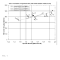
- Fig. 4 schematically shows the spectral efficiency for a modified FSS which limits the maximum number of allocations per subframe to a configurable value.
- the spectral efficiency is depicted over the maximum number of allocations per subframe for a number of user terminals per cell from 1 to 10.
- Fig. 4 shows that increasing the number of allocations per subframe leads to an increase in the spectral efficiency until the number of allocations is smaller or equal to 4. A higher number of allocations per subframe does not lead to an additional gain in spectral efficiency.
- the number of allocations per subframe can be reduced to a certain value without significant performance loss which leads to a much lower load on the PDCCH.
- the reduced load on the PDCCH may enable a smaller dimensioning of the PDCCH, e.g. only 2 instead of 3 symbols.
- a smaller dimensioning of the PDCCH would in turn lead to more user data capacity because the symbol which is no longer needed for the PDCCH can be used for the PDSCH.
- Fig. 5 schematically shows the impact of PDCCH dimensioning and the maximum number of allocation per subframe on the system performance, i.e. cell border throughput and spectral efficiency.
- fig. 5 also shows that if the reduction of the maximum number of allocations enables a reduction of the PDCCH dimensioning, an overall performance gain may be realized.
- LTE enables to apply so-called user specific aggregation levels for the signaling messages on the PDCCH.
- the number of PDCCH resources i.e. Control Channel Elements (CCEs), and total PDCCH power are known for each subframe. Multiple CCEs 1, 2, 4 or 8 can be aggregated to achieve different coding rates.
- the aggregation level needed for a user terminal depends on the channel conditions of the user terminal, and the size of the scheduling grant that must be used for the user terminal.
- Each user terminal is allocated a candidate set of PDCCH channels for each possible aggregation level. Therefore the required PDCCH capacity for signaling a certain number of allocations not only depends on the number of allocations, i.e.
- an appropriate value for both parameters number of allocations and PDCCH dimensioning will be determined preferably on a subframe basis.
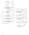
- Fig. 6 schematically shows an example of a basic method for a co-optimization of scheduling and PDCCH dimensioning according to an embodiment of the invention.
- the embodiment depicted in fig. 6 exemplarily only considers the downlink.
- the number of allocations in uplink is not optimized, instead it is assumed that the uplink scheduling is done before the described method is executed and therefore it is already known how many PDCCH resources are required by the uplink.
- a proportional fair scheduler is assumed that calculates resource scheduling priorities, i.e. fairness metrics F k,n ( i ), for a resource block n of a user terminal k based e.g. on an expected data throughput I k,n ( i ) and on an average data throughput A k ( i ) as described above.
- the total priority of a user terminal i.e.
- the sum of all its resource scheduling priorities serves for determining the set of scheduled user terminals to be served during a subframe.
- the expected data throughput I k,n ( i ) per user terminal and per resource which can be deduced from a frequency selective feedback, as e.g. a Channel Quality Indicator (CQI) value h k,n ( i ), is exploited for determining the best PDCCH configuration, i.e. the one with the highest sum capacity or overall data throughput.
- CQI Channel Quality Indicator
- step 1 when the method is started, it considers a PDCCH size of 3 symbols per subframe, which is the maximum in the current LTE standard, i.e. a parameter numPDCCHSymbols indicating the PDCCH size is set to 3.
- step 2 a parameter bestSchedule indicating the best scheduling decision with the highest sum capacity or overall data throughput, i.e. with the highest sum data throughput of all user terminals, is instantiated.
- the sum of all resource scheduling priorities, i.e. the fairness metrics F k,n ( i ), of all resource blocks serves for determining the set of scheduled user terminals to be served during a subframe as a starting point without any restrictions.
- a parameter currentSchedule indicating the momentary scheduling decision is set to said set of scheduled user terminals determined without any restrictions.
- step 4 it is checked whether there is sufficient PDCCH capacity to signal the corresponding scheduling decision for the set of scheduled user terminals indicated by the parameter currentSchedule.
- the PDCCH resources required to signal the UL scheduling which has been determined before is considered, i.e. the PDDCH capacity for signaling DL scheduling is reduced by the PDCCH resources required to signal the UL scheduling.
- step 6 the parameter bestSchedule indicating the best scheduling decision with the highest sum capacity is set to the set of scheduled user terminals indicated by the parameter currentSchedule.
- step 7 the number of PDCCH symbols is reduced by 1, and the parameter currentSchedule indicating the scheduling decision is updated by adding free resources from removing the PDCCH symbol to the DL allocations.
- the size of the PDSCH is increased by on symbol.
- I k,n ( i ) changes, because the size of the resource block is changed. So the user terminals can simply increase the number of scheduled bytes by the additional capacity, if they still have pending data. If a user terminal has no more pending data, certain resource blocks might become unused. In this case the unused resources are scheduled to the user terminal of the already scheduled user terminals, which has the highest priority for this resource block and which has still pending data.
- step 8 it is checked if the parameter numPDCCHSymbols indicating the PDCCH size is greater than 0. If this is the case, the process restarts with step 4.
- step 9 the set of scheduled user terminals with the best sum capacity indicated by the parameter bestSchedule and the corresponding PDCCH size are applied.
- the DL allocation i.e. user terminal, with the lowest data throughput or lowest elapsed time since a last scheduling is removed.
- the DL allocation is removed based on a type of transmission, e.g. initial transmission or retransmission.
- step 4 it is again checked in step 4 whether there is sufficient PDCCH capacity to signal the corresponding scheduling decision for the set of scheduled user terminals indicated by the parameter currentSchedule.
- the described method is enhanced by also optimizing the number of allocations in uplink.
- the method is similar to the method described above in fig. 6 , but also uplink allocations might be removed in step 11 as described above if the PDCCH capacity is not sufficient detected in step 4 as described above. Additionally the check performed in step 5 as described above whether the scheduling decision maximizes the capacity has to consider the uplink capacity as well.
- the corresponding processing steps can be performed e.g. in the modem unit boards MU1-MU3 and the control unit board CU1 of the base station BS as depicted in fig. 2 and described above.
Landscapes
- Engineering & Computer Science (AREA)
- Quality & Reliability (AREA)
- Computer Networks & Wireless Communication (AREA)
- Signal Processing (AREA)
- Mobile Radio Communication Systems (AREA)
Priority Applications (1)
| Application Number | Priority Date | Filing Date | Title |
|---|---|---|---|
| EP13305589.7A EP2802182A1 (de) | 2013-05-06 | 2013-05-06 | Verfahren zur Einplanung von Benutzerendgeräten auf Ressourcen sowie Basisstation dafür |
Applications Claiming Priority (1)
| Application Number | Priority Date | Filing Date | Title |
|---|---|---|---|
| EP13305589.7A EP2802182A1 (de) | 2013-05-06 | 2013-05-06 | Verfahren zur Einplanung von Benutzerendgeräten auf Ressourcen sowie Basisstation dafür |
Publications (1)
| Publication Number | Publication Date |
|---|---|
| EP2802182A1 true EP2802182A1 (de) | 2014-11-12 |
Family
ID=48520864
Family Applications (1)
| Application Number | Title | Priority Date | Filing Date |
|---|---|---|---|
| EP13305589.7A Withdrawn EP2802182A1 (de) | 2013-05-06 | 2013-05-06 | Verfahren zur Einplanung von Benutzerendgeräten auf Ressourcen sowie Basisstation dafür |
Country Status (1)
| Country | Link |
|---|---|
| EP (1) | EP2802182A1 (de) |
Cited By (1)
| Publication number | Priority date | Publication date | Assignee | Title |
|---|---|---|---|---|
| CN113039846A (zh) * | 2018-11-26 | 2021-06-25 | 瑞典爱立信有限公司 | 用于在上行链路中调度用户设备的网络节点和在其中执行的方法 |
Citations (1)
| Publication number | Priority date | Publication date | Assignee | Title |
|---|---|---|---|---|
| WO2012151064A2 (en) * | 2011-05-02 | 2012-11-08 | Research In Motion Limted | Methods and system of wireless communication with remote radio heads |
-
2013
- 2013-05-06 EP EP13305589.7A patent/EP2802182A1/de not_active Withdrawn
Patent Citations (1)
| Publication number | Priority date | Publication date | Assignee | Title |
|---|---|---|---|---|
| WO2012151064A2 (en) * | 2011-05-02 | 2012-11-08 | Research In Motion Limted | Methods and system of wireless communication with remote radio heads |
Non-Patent Citations (3)
| Title |
|---|
| FUJITSU: "Summary of email discussion on CSS for ePDCCH", 3GPP DRAFT; R1-121193 CSS ON EPDCCH, 3RD GENERATION PARTNERSHIP PROJECT (3GPP), MOBILE COMPETENCE CENTRE ; 650, ROUTE DES LUCIOLES ; F-06921 SOPHIA-ANTIPOLIS CEDEX ; FRANCE, vol. RAN WG1, no. Jeju, Korea; 20120326 - 20120330, 29 March 2012 (2012-03-29), XP050600070 * |
| NOKIA ET AL: "E-PDCCH design principles", 3GPP DRAFT; R1-114329 E-PDCCH DESIGN PRINCIPLES, 3RD GENERATION PARTNERSHIP PROJECT (3GPP), MOBILE COMPETENCE CENTRE ; 650, ROUTE DES LUCIOLES ; F-06921 SOPHIA-ANTIPOLIS CEDEX ; FRANCE, vol. RAN WG1, no. San Francisco, USA; 20111114 - 20111118, 8 November 2011 (2011-11-08), XP050562195 * |
| TOSHIBA: "Performance evaluation of Rel-10 feedback extensions", 3GPP DRAFT; R1-103282-PERFORMACE EVALUATION OF REL-10 FEEDBACK EXTENSIONS, 3RD GENERATION PARTNERSHIP PROJECT (3GPP), MOBILE COMPETENCE CENTRE ; 650, ROUTE DES LUCIOLES ; F-06921 SOPHIA-ANTIPOLIS CEDEX ; FRANCE, vol. RAN WG1, no. Montreal, Canada; 20100510 - 20100514, 7 May 2010 (2010-05-07), XP050598369 * |
Cited By (3)
| Publication number | Priority date | Publication date | Assignee | Title |
|---|---|---|---|---|
| CN113039846A (zh) * | 2018-11-26 | 2021-06-25 | 瑞典爱立信有限公司 | 用于在上行链路中调度用户设备的网络节点和在其中执行的方法 |
| US11902964B2 (en) | 2018-11-26 | 2024-02-13 | Telefonaktiebolaget Lm Ericsson (Publ) | Network node and method performed therein for scheduling user equipment in uplink |
| CN113039846B (zh) * | 2018-11-26 | 2024-03-15 | 瑞典爱立信有限公司 | 用于在上行链路中调度用户设备的网络节点和在其中执行的方法 |
Similar Documents
| Publication | Publication Date | Title |
|---|---|---|
| EP2847884B1 (de) | Einplannen einer benutzervorrichtung in einem kommunikationssystem | |
| JP6379214B2 (ja) | 干渉の効果的な除去および抑制のための干渉パラメータのシグナリング | |
| KR101607097B1 (ko) | 무선 패킷 데이터 송신들의 페이로드 세분화를 위한 장치, 방법 및 컴퓨터 판독 가능 매체 | |
| EP2858443B1 (de) | Datenübertragungsverfahren, basisstation und benutzervorrichtung | |
| JP5615453B2 (ja) | 基地局装置、移動局装置、通信方法 | |
| EP3033903B1 (de) | Verfahren für kanalqualitätsbericht | |
| KR101683597B1 (ko) | 무선 통신 시스템에서 복수의 주파수를 사용하는 단말의 전력 증감 요청 방법 및 장치 | |
| US9414396B2 (en) | Apparatus, base station transceiver, method, and computer program for assigning a radio resource | |
| EP2741533A1 (de) | Verfahren zur Interferenzkoordination zwischen Zellen und eine Basisstation dafür | |
| EP2296408A1 (de) | Verfahren zur zeitlichen Einplanung von Übertragungen zwischen einer Basisstation und Teilnehmergeräten und Kommunikationsnetz dafür | |
| JP6886399B2 (ja) | 無線端末、基地局、及びプロセッサ | |
| CA2803860A1 (en) | Radio communication method and radio communication apparatus | |
| US8842625B2 (en) | Wireless scheduling considering overhead cost estimate | |
| US10999883B1 (en) | Use of uplink power headroom as a basis to control configuration of dual-connectivity service | |
| US11178675B2 (en) | Apparatuses, methods and computer programs for a mobile communication system comprising a base station transceiver and a mobile transceiver | |
| EP2389040A1 (de) | Verfahren zur Überwachung und Steuerung einer Last in einem Kommunikationsnetzwerk und Basisstation dafür | |
| EP2262336A1 (de) | Verfahren zur verbesserten Verbindungsanpassung in drahtlosen zellulären Netzwerken | |
| US11096067B2 (en) | Method for coordination of transmission from base stations, and a base station therefor | |
| EP2819478A1 (de) | Ressourcenzuweisungsverfahren, Basistation und Endgerät | |
| EP2802182A1 (de) | Verfahren zur Einplanung von Benutzerendgeräten auf Ressourcen sowie Basisstation dafür | |
| EP2688349B1 (de) | Verfahren zur Signalisierung einer Steuerungsinformation und Netzwerkvorrichtungen dafür | |
| EP2542005A1 (de) | Verfahren zur Signalisierung von Zuweisungen von Unterrahmen, Basisstation und Benutzerendgerät dafür | |
| EP2701438B1 (de) | Verfahren zur Koordinierung von Übertragungen von Basisstationen sowie Netzwerkvorrichtungen dafür | |
| EP2884795B1 (de) | Verfahren zur drahtlosen kommunikation mittels weitgehend leeren subframes und kommunikationsnetz |
Legal Events
| Date | Code | Title | Description |
|---|---|---|---|
| PUAI | Public reference made under article 153(3) epc to a published international application that has entered the european phase |
Free format text: ORIGINAL CODE: 0009012 |
|
| 17P | Request for examination filed |
Effective date: 20130506 |
|
| AK | Designated contracting states |
Kind code of ref document: A1 Designated state(s): AL AT BE BG CH CY CZ DE DK EE ES FI FR GB GR HR HU IE IS IT LI LT LU LV MC MK MT NL NO PL PT RO RS SE SI SK SM TR |
|
| AX | Request for extension of the european patent |
Extension state: BA ME |
|
| R17P | Request for examination filed (corrected) |
Effective date: 20150330 |
|
| RBV | Designated contracting states (corrected) |
Designated state(s): AL AT BE BG CH CY CZ DE DK EE ES FI FR GB GR HR HU IE IS IT LI LT LU LV MC MK MT NL NO PL PT RO RS SE SI SK SM TR |
|
| 17Q | First examination report despatched |
Effective date: 20171108 |
|
| RAP1 | Party data changed (applicant data changed or rights of an application transferred) |
Owner name: ALCATEL LUCENT |
|
| GRAP | Despatch of communication of intention to grant a patent |
Free format text: ORIGINAL CODE: EPIDOSNIGR1 |
|
| RIC1 | Information provided on ipc code assigned before grant |
Ipc: H04W 72/12 20090101AFI20190402BHEP |
|
| INTG | Intention to grant announced |
Effective date: 20190416 |
|
| STAA | Information on the status of an ep patent application or granted ep patent |
Free format text: STATUS: THE APPLICATION IS DEEMED TO BE WITHDRAWN |
|
| 18D | Application deemed to be withdrawn |
Effective date: 20190827 |