EP2802194A2 - Boîtier encapsulé résistant à la pression doté d'un dispositif de refroidissement - Google Patents
Boîtier encapsulé résistant à la pression doté d'un dispositif de refroidissement Download PDFInfo
- Publication number
- EP2802194A2 EP2802194A2 EP14167173.5A EP14167173A EP2802194A2 EP 2802194 A2 EP2802194 A2 EP 2802194A2 EP 14167173 A EP14167173 A EP 14167173A EP 2802194 A2 EP2802194 A2 EP 2802194A2
- Authority
- EP
- European Patent Office
- Prior art keywords
- housing
- liquid
- monitoring
- unit
- heat exchanger
- Prior art date
- Legal status (The legal status is an assumption and is not a legal conclusion. Google has not performed a legal analysis and makes no representation as to the accuracy of the status listed.)
- Granted
Links
Images
Classifications
-
- H—ELECTRICITY
- H05—ELECTRIC TECHNIQUES NOT OTHERWISE PROVIDED FOR
- H05K—PRINTED CIRCUITS; CASINGS OR CONSTRUCTIONAL DETAILS OF ELECTRIC APPARATUS; MANUFACTURE OF ASSEMBLAGES OF ELECTRICAL COMPONENTS
- H05K7/00—Constructional details common to different types of electric apparatus
- H05K7/20—Modifications to facilitate cooling, ventilating, or heating
- H05K7/20218—Modifications to facilitate cooling, ventilating, or heating using a liquid coolant without phase change in electronic enclosures
- H05K7/20281—Thermal management, e.g. liquid flow control
-
- H—ELECTRICITY
- H05—ELECTRIC TECHNIQUES NOT OTHERWISE PROVIDED FOR
- H05K—PRINTED CIRCUITS; CASINGS OR CONSTRUCTIONAL DETAILS OF ELECTRIC APPARATUS; MANUFACTURE OF ASSEMBLAGES OF ELECTRICAL COMPONENTS
- H05K5/00—Casings, cabinets or drawers for electric apparatus
- H05K5/06—Hermetically-sealed casings
-
- H—ELECTRICITY
- H05—ELECTRIC TECHNIQUES NOT OTHERWISE PROVIDED FOR
- H05K—PRINTED CIRCUITS; CASINGS OR CONSTRUCTIONAL DETAILS OF ELECTRIC APPARATUS; MANUFACTURE OF ASSEMBLAGES OF ELECTRICAL COMPONENTS
- H05K5/00—Casings, cabinets or drawers for electric apparatus
- H05K5/06—Hermetically-sealed casings
- H05K5/069—Other details of the casing, e.g. wall structure, passage for a connector, a cable, a shaft
-
- H—ELECTRICITY
- H05—ELECTRIC TECHNIQUES NOT OTHERWISE PROVIDED FOR
- H05K—PRINTED CIRCUITS; CASINGS OR CONSTRUCTIONAL DETAILS OF ELECTRIC APPARATUS; MANUFACTURE OF ASSEMBLAGES OF ELECTRICAL COMPONENTS
- H05K7/00—Constructional details common to different types of electric apparatus
- H05K7/20—Modifications to facilitate cooling, ventilating, or heating
- H05K7/20218—Modifications to facilitate cooling, ventilating, or heating using a liquid coolant without phase change in electronic enclosures
Definitions
- the invention relates to a pressure-tightly encapsulated housing with a temperature control device which has a first heat exchanger unit arranged in the interior of the housing and a second heat exchanger unit arranged outside the housing.
- the two heat exchanger units are connected to each other via a fluid circuit. In this way, components in the flameproof enclosure can be cooled and / or heated as needed.
- Such a housing is made, for example WO 2010/132211 A1 known.
- the two heat exchanger units in or outside the housing are connected to each other viaridgerohrohe, which are guided through the wall of the housing.
- the wall penetration of the pipes can impair the ignition safety of the housing.
- the end DE 101 52 510 A1 known flameproof enclosure has a coolant passage in which a pressure-resistant lock with a plurality of passage channels for the liquid coolant is present.
- the barrier is traversed by the coolant and provides the Zünd toschlagschreib within the tube between the interior of the flameproof enclosure and the environment ago. Such barriers increase the flow resistance, which in turn results in the delivery of the coolant along the coolant circuit requiring increased power.
- US 2010/0284150 A1 describes an explosion-proof Casing.
- two flame arrestors made of sintered material are inserted into connecting pieces on wall outlets.
- this approach corresponds to the content of DE 101 52 510 A1 ,
- the cooling in the housing is effected by an air circulation.
- the air cooling of components inside the housing is insufficient in many cases.
- the pressure-tight encapsulated housing has a temperature control device with two heat exchanger units, which are connected to each other via a fluid circuit.
- the liquid circuit circulates a liquid heat transfer medium.
- the first heat exchanger unit is arranged inside the housing.
- the second heat exchanger unit is located outside the housing. Heat can be transferred to the liquid via the one heat exchanger unit, and heat can be absorbed by the liquid via the respective other heat exchanger unit and the heated liquid can be cooled. This makes it possible to temper the interior of the housing or the components present there, ie to cool or to heat. In many cases will it must be necessary to absorb the heat emitted by the electrical components inside the housing by means of the first heat exchanger unit and to transport it via the liquid in the fluid circuit to the outside to the second heat exchanger unit and to deliver it to the environment.
- the liquid circuit has in the housing a supply line and a return line, which are each fluidically connected to the first heat exchanger unit.
- the two lines are connected to a respective execution unit.
- the supply line and the return line are each fluidly connected to a passage of the associated passage unit.
- the grommet is fire-arrestingly secured in one of the walls of the housing via a firing-resistant fastening means, the passageway extending through the wall inside the grommet.
- the passage is preferably cylindrical and extends through a passage body of the passage unit therethrough.
- the flameproof enclosure also includes at least one liquid monitoring sensor. It is also possible to provide a plurality of liquid monitoring sensors and, for example, to associate each passage unit with a separate liquid monitoring sensor.
- the at least one liquid monitoring sensor generates a liquid monitoring signal, which is transmitted to a monitoring unit.
- the liquid monitoring signal of the at least one liquid monitoring sensor describes the filling of the through-channels or of the respectively assigned through-channel with liquid.
- the liquid monitoring signal is characteristic of whether the cross-section of the passageway (s) is sufficiently and in particular completely filled with liquid of the liquid circuit or are, that is, whether within a through-channel no ignition gap may have formed or not.
- the liquid monitoring sensor can be designed, for example, as a fill level sensor. It is also possible to indirectly determine the level via a pressure sensor that measures the fluid pressure in the fluid circuit. Also via volume or mass flow sensors, temperature sensors or the like, the filling of the passageways can be determined directly or indirectly. There may also be a plurality of liquid monitoring sensors having different characteristic sizes, e.g. Record level, pressure or temperature.
- the monitoring unit is connected to a controllable separating device.
- An electrical supply line leads into the interior of the pressure-tightly encapsulated housing in order to supply the electrical and / or electronic components present there with electrical energy.
- the separator is inserted into at least one conductor of the supply line and can supply electrical energy and thus providing of electrical voltage inside the housing when it is in its disconnected state.
- the monitoring unit can switch the separating device depending on the liquid monitoring signal in their disconnected state, so that unsafe operating conditions can be avoided and the risk of explosion can be excluded.
- the monitoring unit is in particular configured to evaluate the liquid monitoring signal. If insufficient explosion protection is determined on the basis of this evaluation, the monitoring unit generates a first output signal. Otherwise, a second output signal can be generated.
- the first output signal is produced when the at least one liquid monitoring signal indicates that at least one of the two through channels has insufficient liquid filling. This could form a spark gap. Such an operating condition is thus avoided.
- the first output signal which characterizes inadequate explosion protection, is used to switch the isolator to its disconnect state and break the voltage and power supply to the components in the housing.
- an alarm or a corresponding indication signal for an operator could also be generated based on the first output signal and / or the second output signal.
- the monitoring unit may also be connected to a temperature sensor which generates a temperature signal characteristic of the surface temperature on the outer surface of the housing.
- the temperature signal can be evaluated in the monitoring unit. In particular, when the temperature signal becomes a predetermined threshold exceeds, the insufficient explosion protection characterizing third output signal caused by the monitoring unit and triggered an alarm and / or switching the separator in the disconnected state. Too high a surface temperature in the housing can cause an explosion in an explosive environment. This danger is avoided by monitoring the surface temperature.
- the circulation of the liquid in the liquid loop is continued when too high a surface temperature of the casing has been detected to lower the temperature.
- An optional liquid circuit existing in the liquid circuit thus remains in operation.
- the temperature sensor for monitoring the surface temperature may be disposed on the outer surface of the housing for directly measuring the surface temperature.
- Another possibility is to determine the temperature at the first heat exchanger unit, which is also characteristic of the surface temperature.
- a plurality of temperature sensors may also be arranged at one or more of said locations. As a result, redundant temperature information can be determined, which further increases safety.
- each feedthrough unit has a feedthrough body in which the passageway extends.
- the lead-through body has an ignition-proof external thread.
- Sealing flange be present in order to achieve a seal between the feedthrough body and the housing wall, in particular the outer surface. This can increase the degree of protection according to EN 60529.
- An ignition-proof attachment to the wall of the housing can take place via the ignition-proof external thread of the leadthrough body.
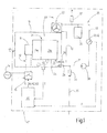
- FIG. 1 shows an explosion-proof housing 10 in the protection type flameproof enclosure (Ex-d).
- the housing 10 one or more electrical and / or electronic components 11 are arranged.
- an electrical supply line 12 the at least one component 11 is supplied with electrical energy.
- the supply line 12 is fire arrester passed through a wall 13 of the housing 10.
- the supply line 12 may have two or more electrical conductors. It is connected, for example, to a mains voltage source 14.
- a controllable separator 15 is arranged in the supply line 12 or in at least one conductor of the supply conductor 12 .
- the separator 15 interrupts the voltage and power supply of the at least one component 11 in its disconnected state. In this disconnected state, the separator 15 can be switched by a corresponding control signal S.
- the electrical wires are in FIG. 1 to illustrate the difference with respect to the liquid lines later described by dashed lines.
- the housing 10 is associated with a temperature control device 20 for controlling the temperature of the at least one component 11.
- the temperature control device 20 can serve to cool and / or heat the at least one component 11.
- the tempering device 20 has a first heat exchanger unit 21 arranged in the interior of the housing 10 and a second heat exchanger unit 22 arranged outside the housing 10.
- the two heat exchanger units 21, 22 are connected to each other via a fluid circuit 23.
- a liquid for example water or oil, which serves as a heat transfer medium.
- the structure of the heat exchanger units 21, 22 is basically arbitrary. There are a variety of possibilities.
- the first heat exchanger unit 21 has a heat-transferring contact with the at least one component 11 standing heat transfer part 21a as well as a heat-transmitting contact with the heat transfer part 21a standing medium-side part 21b.
- the medium-side part 21b is connected to the liquid circuit and flows through the circulating liquid there.
- the fluid circuit 23 has a supply line 24 and a return line 25, which are each fluidly connected to the first heat exchanger unit 21 and, according to the example, to the medium-side part 21b. Both the feed line 24, and the return line 25 are connected in the interior of the housing 10 in each case to a passage unit 26.
- Each feedthrough unit 26 has a through-passage 27 (FIG. FIG. 3 ), through which liquid can flow into the feed line 24 or from the return line 25.
- the execution units 26 are ignition-proof inserted into a wall 13 of the housing 10.
- the liquid circuit 23 to a liquid pump 30, which is arranged according to the example outside of the housing 10 and therefore designed to be explosion-proof.
- the liquid pump 30 could be arranged in the housing 10 explosion proof. Downstream the fluid pump 30 is connected, for example via a first fluid line 31 fluidly via one of the two processing units 26 to the supply line 24.
- a second liquid line 32 of the liquid circuit 23 is fluidly connected via the respective other passage unit 26 to the return line 25 and leads to the second heat exchanger unit 22.
- a third liquid line 33 of the liquid circuit 23 leads from the second heat exchanger unit 22 back to the liquid pump 30. Thus creates a closed Liquid circuit 23.
- a pressure relief valve 34 is connected to the first fluid line 31, so that at high fluid pressure downstream of the fluid pump, an amount of liquid from the fluid circuit 23 can be dissipated to reduce the pressure.
- the pressure relief valve 34 is connected to a pressure relief line 35.
- a surge tank may be connected to the liquid circuit 23 and, for example, the third liquid line 33.
- the expansion tank 36 is preferably designed as a diaphragm accumulator. About the surge tank 36 can be ensured that the liquid pump 30 is always provided a sufficient amount of liquid available. In order to be able to remove gas and in particular air from the liquid circuit 23, this also has a bleeder 37 in the exemplary embodiment. This deaerator 37 is particularly advantageous when a gaseous diaphragm accumulator is used as a surge tank 36 to penetrate into the liquid gas or air again to be able to remove from the fluid circuit 23.
- At least one liquid monitoring sensor 41 is present, which is designed as a pressure sensor 42, for example.
- the at least one liquid monitoring sensor 41 generates a liquid monitoring signal F, which is transmitted to the monitoring unit 40 for evaluation.
- only one liquid monitoring sensor 41 in the form of the pressure sensor 42 is present.
- the pressure sensor 42 measures the pressure at a location of the fluid circuit 23.
- the fluid pressure at the location of the fluid circuit 23 is measured, at which there is usually the lowest fluid pressure.
- the pressure sensor 42 is therefore arranged upstream of the liquid pump 30 at the suction side and, for example, inserted into the third liquid line 33.
- the fluid pressure could also be measured at several points in the coolant circuit 23 and in each case a fluid monitoring signal F convinced and transmitted to the monitoring unit 40.
- the liquid pressure in the liquid circuit 23 serves as a measure of whether the passageways 27 of the two processing units 26 are sufficiently filled with liquid, so that there can form no Zündspalte within the through-channel 27 there. If the liquid preferably completely closes the cross-section of the passage 27, the formation of a spark gap in the passage 27 is avoided. This is inventively via the at least one liquid monitoring sensor 41st supervised. If the fluid pressure inside the fluid circuit 23 is sufficiently high at any point, then the fluid lines are completely filled with fluid and the formation of a spark gap is avoided. Therefore, for example, a pressure sensor 42 is used as the liquid monitoring sensor 41.
- a liquid level sensor which directly measures the level of liquid in the liquid circuit 23 could also be used as the liquid monitoring sensor 41. It could also be used several level sensors. For example, each feed unit 26 could be assigned a fill level sensor.
- Another variation of the preferred embodiment is to use one or more temperature sensors as at least one liquid monitoring sensor.
- By measuring the temperature for example at a location inside the housing 10, it can be determined whether sufficient cooling or temperature control takes place. This is ensured when a sufficiently large volume or mass flow of the liquid circulates through the liquid circuit 23.
- a temperature evaluation can thus indirectly indicate the filling in the liquid circuit 23 and consequently also in the through channels 27.
- the monitoring unit 40 is also transmitted a temperature signal T of a temperature sensor 45 in the embodiment.
- the temperature sensor 45 serves to determine the surface temperature at at least one point on the outer surface 46 of the housing 10. Regardless of whether different surface temperatures are set at different locations on the outer surface 46 of the housing 10, the currently prevailing maximum surface temperature value on the outer surface 46 is sufficient of the housing 10 to determine. The surface temperature must not exceed a specified value. Otherwise, the housing 10 itself could serve as a source of ignition in a potentially explosive environment.
- the temperature sensor 45 therefore generates a temperature signal T which describes the surface temperature or the currently prevailing maximum surface temperature value on the outer surface 46.
- the temperature sensor 45 may be disposed directly on the outer surface 46 of the housing 10 and measure the surface temperature.
- a plurality of temperature sensors 45 can be arranged on the outer surface 46 of the housing 10 at different locations in order to determine the currently prevailing maximum surface temperature value, in particular if the surface temperatures of the housing 10 at different Positions may differ from each other.
- the temperature may also be detected at at least one other location that is characteristic or determinative of the surface temperature at the outer surface 46, for example the temperature in the atmosphere inside the housing 10 and / or the temperature at the first heat exchanger unit 21 and / or the temperature at the at least one component 11. Exemplary alternative or additional possibilities for arranging a temperature sensor 45 are shown in FIG FIG. 1 illustrated with dotted lines.
- FIG. 1 The arrangement according to FIG. 1 works as follows:
- At least one electrical and / or electronic component 11 within the pressure-tightly encapsulated housing 10 is tempered, for example cooled, by means of the temperature control device 20.
- the heat is transferred via the first heat exchanger unit 21 to the liquid serving as the heat transfer medium and transported by means of the liquid to the second heat exchanger unit 22 outside the housing. There, the heat is released to the environment.
- the second heat exchanger unit 22 may, for example, have a fan.
- the circulation of the liquid is maintained via the liquid pump 30.
- the explosion-proof state of the housing 10 is monitored. If the temperature signal T rises above a predetermined threshold, the explosion safety is no longer given. The monitoring unit 40 then generates a third output signal A3 characterizing the insufficient explosion protection.
- a first output signal A1 indicating the insufficient explosion protection is generated when the filling of the through-channels 27 of the two liquid-conducting units 26 is insufficient.
- the liquid monitoring signal F is evaluated by the monitoring unit 40, for example according to the pressure measured by the pressure sensor 42 in the liquid circuit 23. If the pressure is insufficient, 27 ignition gaps can form in the passage channels, so that the state of the flameproof enclosure (Ex-d) is no longer guaranteed.
- the monitoring unit 40 Otherwise, if the filling of the through channels is sufficient and the surface temperature of the outer surface 46 of the housing 10 is within the allowable range, the monitoring unit 40 generates a second output signal A2 indicating that the monitored parameters meet explosion protection requirements.
- the output signals A1, A2, A3 can be used as a control signal for the separator 15. If the second output signal A2 is generated, the separating device 15 remains in its conducting state and makes it possible to supply the at least one component 11 with electrical energy. As soon as the first output signal A1 and / or the third output signal A3 are generated, this serves as a control signal S for switching over the separating device 15 into the disconnected state. The voltage and power supply of the at least one component 11 with electrical energy via the supply line 12 is prevented.
- an optical and / or audible and / or haptic alarm signal for an operator could be generated via the first output signal A1 and / or the third output signal A3, which would provide the insufficient explosion protection and optionally also the reason (too high surface temperature at the third output A3 and / or too low liquid level in the passageway at the first output signal A1) indicates. It is understood that it is also possible to visually and / acoustically and / haptically display or output the proper state when the second output signal A2 is generated by the monitoring unit 40.
- the flameproof enclosure 10 and the temperature control 20 may be arranged in and / or on an outer housing 47.
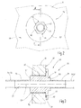
- FIG. 3 An exemplary embodiment of a feedthrough unit 26 is shown in FIG FIG. 3 illustrated.
- the passage unit 26 has a passage body 50, which is penetrated by the passageway 27.
- the passage 27 is cylindrical and extends along a longitudinal axis L.
- the two mouths of the passage 27 are each provided on a tubular end portion 51 of the passage body.
- the two tubular end portions are connected to each other via a central portion 52 having a larger outer diameter.
- a spark-proof external thread 53 is present at the central portion 52.
- the external thread 53 is assigned an ignition-puncture internal thread 54 in the embodiment.
- the internal thread 54 is present in the embodiment directly in the wall 13 of the housing 10 or in
- the bushing body 50 is thus screwed with its external thread 53 directly into the through hole limited by the internal thread 54 in the wall 13.
- the external thread 53 and the internal thread 54 together represent a flameproof fastening means 55 for fixing the passage unit 26 to the wall 13 of the housing 10, as shown in FIG FIG. 3 is shown.
- an ignition-punctured thread gap 56 is formed by the threaded engagement.
- the feedthrough body 50 has a sealing flange 57, whose outer diameter is greater than that of the external thread 53.
- a sealing flange 57 Between the sealing flange 57 and the wall 13 of the housing 10, at least one seal 58 may be arranged, in particular in order to increase the degree of protection.
- the seal 58 is inserted in the embodiment described here in an annular, in particular annular groove 59.
- the groove 59 is open on the outer thread 53 facing side of the sealing flange 57 and can thus come into contact with the wall 13 and with the outer surface 46.
- an engagement part 60 for engaging the sealing body 50 with a tool can be present on the sealing body 50.
- the attacking part 60 is designed, for example, as an external hexagon with six engagement surfaces 61 for a fork wrench or a similar tool. As a result, the bushing body 50 can be turned with a tool when tightened and fixedly attached to the wall 13 of the housing 10 or released again.
- the lines of the liquid circuit 23 are each connected to a tubular end portion 51 inside the housing 10 and outside of the housing 10, which in FIG. 3 only schematically illustrated by dashed lines.
- the liquid used as the heat transfer medium is selected such that neither the liquid itself, nor their decomposition products are flammable or represent explosive substances or contain or release.
- the invention relates to a pressure-tight encapsulated housing 10 with a tempering device 20 and a method for monitoring the flameproof enclosure 10.
- the temperature control device includes a first heat exchanger unit 21 in the interior of the housing 10 and a second heat exchanger unit 22 outside the housing 10.
- the temperature control device includes a first heat exchanger unit 21 in the interior of the housing 10 and a second heat exchanger unit 22 outside the housing 10.
- About liquid lines of a fluid circuit 23, the heat exchanger units 21, 22 are fluidly connected to each other.
- execution units 26 In the wall 13 of the housing 10 sit two execution units 26, each having a passageway 27.
- the passage channels 27 are part of the fluid circuit 23 and fluidly connected both inside and outside of the housing with the respective associated lines.
- a liquid monitoring sensor 41 generates a liquid monitoring signal F indicating when the filling of a through-passage 27 in a passage unit 26 is insufficient.
- the liquid monitoring signal F is transmitted to a monitoring unit 40, which evaluates the signal. If this evaluation shows that the degree of filling or the fill level within the passage 27 is too low and the requirements for the explosion protection are no longer met, the monitoring unit 40 generates a first output signal A1. About this output signal A1, an alarm can be executed and / or the components 11 are switched without voltage and current in the housing 10.
Landscapes
- Engineering & Computer Science (AREA)
- Microelectronics & Electronic Packaging (AREA)
- Physics & Mathematics (AREA)
- Thermal Sciences (AREA)
- Measuring Fluid Pressure (AREA)
- Cooling Or The Like Of Electrical Apparatus (AREA)
Applications Claiming Priority (1)
| Application Number | Priority Date | Filing Date | Title |
|---|---|---|---|
| DE102013104627.4A DE102013104627B3 (de) | 2013-05-06 | 2013-05-06 | Anordnung aus einem druckfest gekapselten Gehäuse und einer Temperiervorrichtung und Verfahren zu deren Überwachung |
Publications (3)
| Publication Number | Publication Date |
|---|---|
| EP2802194A2 true EP2802194A2 (fr) | 2014-11-12 |
| EP2802194A3 EP2802194A3 (fr) | 2017-08-09 |
| EP2802194B1 EP2802194B1 (fr) | 2018-09-05 |
Family
ID=50630696
Family Applications (1)
| Application Number | Title | Priority Date | Filing Date |
|---|---|---|---|
| EP14167173.5A Not-in-force EP2802194B1 (fr) | 2013-05-06 | 2014-05-06 | Boîtier encapsulé résistant à la pression doté d'un dispositif de refroidissement |
Country Status (5)
| Country | Link |
|---|---|
| US (1) | US9414522B2 (fr) |
| EP (1) | EP2802194B1 (fr) |
| CN (1) | CN104219935B (fr) |
| BR (1) | BR102014010840A2 (fr) |
| DE (1) | DE102013104627B3 (fr) |
Families Citing this family (5)
| Publication number | Priority date | Publication date | Assignee | Title |
|---|---|---|---|---|
| JP6565611B2 (ja) * | 2015-11-04 | 2019-08-28 | 富士通株式会社 | 情報処理装置 |
| DE102016224064A1 (de) | 2016-12-02 | 2018-06-07 | Eaton Protection Systems Ip Gmbh & Co. Kg | Elektrisches/Elektronisches Betriebsmittel, Verfahren zur Kühlung und Überwachung des Betriebsmittels sowie Sicherheitsschalteinrichtung |
| DE102023101875B4 (de) * | 2023-01-26 | 2026-01-15 | Bayerische Motoren Werke Aktiengesellschaft | Kühleinrichtung zum Kühlen einer elektronischen Recheneinrichtung für ein Kraftfahrzeug sowie Kraftfahrzeug |
| CN118263774B (zh) * | 2024-05-30 | 2024-08-06 | 广东诺克电气科技有限公司 | 多信号融合内部故障电弧保护的智能开关柜及其使用方法 |
| CN119169938B (zh) * | 2024-11-22 | 2025-08-01 | 佛山市彩维电器有限公司 | 一种具有拼接保护结构的防爆led显示屏 |
Citations (3)
| Publication number | Priority date | Publication date | Assignee | Title |
|---|---|---|---|---|
| DE10152510A1 (de) | 2001-10-18 | 2003-05-08 | Bartec Sicherheits Schaltanlag | Schutzgehäuse für elektrische Betriebsmittel |
| US20100284150A1 (en) | 2009-05-05 | 2010-11-11 | Cooper Technologies Company | Explosion-proof enclosures with active thermal management using sintered elements |
| WO2010132211A1 (fr) | 2009-05-14 | 2010-11-18 | Cooper Technologies Company | Enceintes antidéflagrantes à gestion thermique active par échange de chaleur |
Family Cites Families (15)
| Publication number | Priority date | Publication date | Assignee | Title |
|---|---|---|---|---|
| CA1122129A (fr) * | 1978-12-21 | 1982-04-20 | John B. Hutchison | Etancheisation de canalisations |
| DE3026881C2 (de) * | 1980-07-16 | 1983-11-24 | Ruhrkohle Ag, 4300 Essen | Drehzahlverstellvorrichtung für Drehstrom-Asynchronmotoren zum Einsatz in explosionsgefährdeten Bereichen, insbesondere in Grubenbauen |
| US4616694A (en) * | 1984-10-22 | 1986-10-14 | Hsieh Shih Yung | Fireproof cabinet system for electronic equipment |
| US4847602A (en) * | 1985-10-18 | 1989-07-11 | Hmw Enterprises, Inc. | Explosion-protected computer terminal |
| DE3632676A1 (de) * | 1986-09-26 | 1988-03-31 | Stahl R Schaltgeraete Gmbh | Explosionsgeschuetztes modulgehaeuse |
| US4809129A (en) * | 1987-11-06 | 1989-02-28 | Hansen Technologies Corporation | Liquid level control system for refrigeration apparatus |
| US5855119A (en) * | 1995-09-20 | 1999-01-05 | Sun Microsystems, Inc. | Method and apparatus for cooling electrical components |
| JP3618696B2 (ja) * | 2001-07-17 | 2005-02-09 | 株式会社大同工業所 | 耐圧防爆容器の冷却装置 |
| US20040008483A1 (en) * | 2002-07-13 | 2004-01-15 | Kioan Cheon | Water cooling type cooling system for electronic device |
| DE10310282A1 (de) * | 2003-03-07 | 2004-09-16 | Rittal Gmbh & Co. Kg | Flüssigkeits-Kühlsystem |
| CN2847817Y (zh) * | 2005-12-06 | 2006-12-13 | 讯凯国际股份有限公司 | 水冷散热系统 |
| CN100469228C (zh) * | 2006-04-26 | 2009-03-11 | 沈正皓 | 恒温式隔爆箱 |
| CN201526750U (zh) * | 2009-11-05 | 2010-07-14 | 北京中矿华飞科技有限公司 | 防爆水接头 |
| US20130205822A1 (en) * | 2010-07-06 | 2013-08-15 | Peter Heiland | System and method for cooling a computer system |
| CN201898129U (zh) * | 2010-12-15 | 2011-07-13 | 兖州东方机电有限公司 | 爆炸环境用内外热交换水冷系统 |
-
2013
- 2013-05-06 DE DE102013104627.4A patent/DE102013104627B3/de not_active Expired - Fee Related
-
2014
- 2014-05-05 US US14/269,376 patent/US9414522B2/en active Active
- 2014-05-06 BR BRBR102014010840-8A patent/BR102014010840A2/pt not_active Application Discontinuation
- 2014-05-06 EP EP14167173.5A patent/EP2802194B1/fr not_active Not-in-force
- 2014-05-06 CN CN201410312403.XA patent/CN104219935B/zh not_active Expired - Fee Related
Patent Citations (3)
| Publication number | Priority date | Publication date | Assignee | Title |
|---|---|---|---|---|
| DE10152510A1 (de) | 2001-10-18 | 2003-05-08 | Bartec Sicherheits Schaltanlag | Schutzgehäuse für elektrische Betriebsmittel |
| US20100284150A1 (en) | 2009-05-05 | 2010-11-11 | Cooper Technologies Company | Explosion-proof enclosures with active thermal management using sintered elements |
| WO2010132211A1 (fr) | 2009-05-14 | 2010-11-18 | Cooper Technologies Company | Enceintes antidéflagrantes à gestion thermique active par échange de chaleur |
Also Published As
| Publication number | Publication date |
|---|---|
| CN104219935B (zh) | 2018-06-19 |
| EP2802194A3 (fr) | 2017-08-09 |
| US9414522B2 (en) | 2016-08-09 |
| US20140328022A1 (en) | 2014-11-06 |
| DE102013104627B3 (de) | 2014-09-25 |
| EP2802194B1 (fr) | 2018-09-05 |
| BR102014010840A2 (pt) | 2014-12-23 |
| CN104219935A (zh) | 2014-12-17 |
Similar Documents
| Publication | Publication Date | Title |
|---|---|---|
| DE102010013313B4 (de) | Gehäuse mit erweitertem Umgebungstemperaturbereich | |
| EP2802194B1 (fr) | Boîtier encapsulé résistant à la pression doté d'un dispositif de refroidissement | |
| EP1829180B1 (fr) | Dispositif pressurisable avec une traversée de câbles étanche | |
| EP2738033B1 (fr) | Dispositif de sécurité pour un véhicule et procédé de commande correspondant | |
| DE102014012086A1 (de) | Anlegetemperaturfühlervorrichtung zum autarken Messen der Temperatur eines Behältnisses | |
| DE102016108840B4 (de) | Vorrichtung zur Temperaturregelung und Verfahren zur Herstellung einer Vorrichtung zur Temperaturregelung | |
| EP2675032B1 (fr) | Appareil de protection contre les surtensions et procédé de diagnostic pour des appareils de protection contre les surtensions à plusieurs étages | |
| DE102013103823B4 (de) | Explosionsgeschütztes Gehäuse und Verfahren zur Überwachung einer ausreichenden Dichtigkeit des explosionsgeschützten Gehäuses | |
| DE102015212334A1 (de) | Vorrichtung und Verfahren zur Kühlung mindestens einer Batteriezelle | |
| DE2340821A1 (de) | Dynamoelektrische maschine mit druckeinrichtung fuer fluessiges kuehlmittel | |
| EP3546895A1 (fr) | Dispositif et procédé de fonctionnement d'un capteur chauffant, en particulier dans une atmosphère explosive | |
| WO2020079072A1 (fr) | Garniture conductrice pour un poste de charge, poste de charge | |
| EP2904269B1 (fr) | Double-cloche d'entrefer et procédé de surveillance d'une double-cloche d'entrefer | |
| WO2018065189A1 (fr) | Appareil électrique équipé de plusieurs unités de refroidissement | |
| EP3549416A1 (fr) | Composant électronique et procédé de refroidissement | |
| DE102004043059A1 (de) | Verfahren und Schutzschaltung zur Temperaturüberwachung von kältemittelgekühlten Elektromotoren | |
| DE2240221C3 (de) | Anzeigeeinrichtung für Isolationsfehler | |
| EP3772622B1 (fr) | Protection contre le transfert de réfrigérant dans un circuit de chauffage après des dommages par congélation de fluide caloporteur dans un échangeur de chaleur | |
| WO2005096329A1 (fr) | Systeme a chambres multiples servant de reservoir de compensation de liquide et son utilisation | |
| DE102016015726A1 (de) | Verfahren zur Herstellung eines Gehäuses und Gehäuse | |
| DE102019106927B3 (de) | Strommessanordnung mit thermischer Isolation | |
| DE102019006343A1 (de) | Messkammer und Messstand | |
| EP1460355A1 (fr) | Méthode pour surveiller un système de chaudière à eau et dispositif pour la mise en oeuvre du procédé | |
| DE102016216362A1 (de) | Grenztemperaturschaltbaugruppe sowie elektrischer Steckverbinder, elektrisches Steuergerät und Leistungselektronikbaugruppe mit einer Grenztemperaturschaltbaugruppe | |
| DE102009020457A1 (de) | Instrumentenschutzkasten zur Aufnahme von elektronischen Geräten, insbesondere zur Aufnahme von elektronischen Messinstrumenten sowie Verfahren zur Regulierung der Bauteil- und/oder Innenraumtemperatur in einem Instrumentenschutzkasten |
Legal Events
| Date | Code | Title | Description |
|---|---|---|---|
| PUAI | Public reference made under article 153(3) epc to a published international application that has entered the european phase |
Free format text: ORIGINAL CODE: 0009012 |
|
| 17P | Request for examination filed |
Effective date: 20140506 |
|
| AK | Designated contracting states |
Kind code of ref document: A2 Designated state(s): AL AT BE BG CH CY CZ DE DK EE ES FI FR GB GR HR HU IE IS IT LI LT LU LV MC MK MT NL NO PL PT RO RS SE SI SK SM TR |
|
| AX | Request for extension of the european patent |
Extension state: BA ME |
|
| PUAL | Search report despatched |
Free format text: ORIGINAL CODE: 0009013 |
|
| AK | Designated contracting states |
Kind code of ref document: A3 Designated state(s): AL AT BE BG CH CY CZ DE DK EE ES FI FR GB GR HR HU IE IS IT LI LT LU LV MC MK MT NL NO PL PT RO RS SE SI SK SM TR |
|
| AX | Request for extension of the european patent |
Extension state: BA ME |
|
| RIC1 | Information provided on ipc code assigned before grant |
Ipc: H05K 7/20 20060101ALI20170704BHEP Ipc: H05K 5/06 20060101AFI20170704BHEP |
|
| STAA | Information on the status of an ep patent application or granted ep patent |
Free format text: STATUS: REQUEST FOR EXAMINATION WAS MADE |
|
| R17P | Request for examination filed (corrected) |
Effective date: 20170922 |
|
| RBV | Designated contracting states (corrected) |
Designated state(s): AL AT BE BG CH CY CZ DE DK EE ES FI FR GB GR HR HU IE IS IT LI LT LU LV MC MK MT NL NO PL PT RO RS SE SI SK SM TR |
|
| GRAP | Despatch of communication of intention to grant a patent |
Free format text: ORIGINAL CODE: EPIDOSNIGR1 |
|
| STAA | Information on the status of an ep patent application or granted ep patent |
Free format text: STATUS: GRANT OF PATENT IS INTENDED |
|
| INTG | Intention to grant announced |
Effective date: 20180504 |
|
| GRAS | Grant fee paid |
Free format text: ORIGINAL CODE: EPIDOSNIGR3 |
|
| GRAA | (expected) grant |
Free format text: ORIGINAL CODE: 0009210 |
|
| STAA | Information on the status of an ep patent application or granted ep patent |
Free format text: STATUS: THE PATENT HAS BEEN GRANTED |
|
| AK | Designated contracting states |
Kind code of ref document: B1 Designated state(s): AL AT BE BG CH CY CZ DE DK EE ES FI FR GB GR HR HU IE IS IT LI LT LU LV MC MK MT NL NO PL PT RO RS SE SI SK SM TR |
|
| REG | Reference to a national code |
Ref country code: GB Ref legal event code: FG4D Free format text: NOT ENGLISH |
|
| REG | Reference to a national code |
Ref country code: CH Ref legal event code: EP |
|
| REG | Reference to a national code |
Ref country code: AT Ref legal event code: REF Ref document number: 1039469 Country of ref document: AT Kind code of ref document: T Effective date: 20180915 |
|
| REG | Reference to a national code |
Ref country code: IE Ref legal event code: FG4D Free format text: LANGUAGE OF EP DOCUMENT: GERMAN |
|
| REG | Reference to a national code |
Ref country code: DE Ref legal event code: R096 Ref document number: 502014009350 Country of ref document: DE |
|
| REG | Reference to a national code |
Ref country code: NL Ref legal event code: MP Effective date: 20180905 |
|
| REG | Reference to a national code |
Ref country code: LT Ref legal event code: MG4D |
|
| PG25 | Lapsed in a contracting state [announced via postgrant information from national office to epo] |
Ref country code: LT Free format text: LAPSE BECAUSE OF FAILURE TO SUBMIT A TRANSLATION OF THE DESCRIPTION OR TO PAY THE FEE WITHIN THE PRESCRIBED TIME-LIMIT Effective date: 20180905 Ref country code: FI Free format text: LAPSE BECAUSE OF FAILURE TO SUBMIT A TRANSLATION OF THE DESCRIPTION OR TO PAY THE FEE WITHIN THE PRESCRIBED TIME-LIMIT Effective date: 20180905 Ref country code: GR Free format text: LAPSE BECAUSE OF FAILURE TO SUBMIT A TRANSLATION OF THE DESCRIPTION OR TO PAY THE FEE WITHIN THE PRESCRIBED TIME-LIMIT Effective date: 20181206 Ref country code: RS Free format text: LAPSE BECAUSE OF FAILURE TO SUBMIT A TRANSLATION OF THE DESCRIPTION OR TO PAY THE FEE WITHIN THE PRESCRIBED TIME-LIMIT Effective date: 20180905 Ref country code: NO Free format text: LAPSE BECAUSE OF FAILURE TO SUBMIT A TRANSLATION OF THE DESCRIPTION OR TO PAY THE FEE WITHIN THE PRESCRIBED TIME-LIMIT Effective date: 20181205 Ref country code: BG Free format text: LAPSE BECAUSE OF FAILURE TO SUBMIT A TRANSLATION OF THE DESCRIPTION OR TO PAY THE FEE WITHIN THE PRESCRIBED TIME-LIMIT Effective date: 20181205 Ref country code: SE Free format text: LAPSE BECAUSE OF FAILURE TO SUBMIT A TRANSLATION OF THE DESCRIPTION OR TO PAY THE FEE WITHIN THE PRESCRIBED TIME-LIMIT Effective date: 20180905 |
|
| PG25 | Lapsed in a contracting state [announced via postgrant information from national office to epo] |
Ref country code: HR Free format text: LAPSE BECAUSE OF FAILURE TO SUBMIT A TRANSLATION OF THE DESCRIPTION OR TO PAY THE FEE WITHIN THE PRESCRIBED TIME-LIMIT Effective date: 20180905 Ref country code: LV Free format text: LAPSE BECAUSE OF FAILURE TO SUBMIT A TRANSLATION OF THE DESCRIPTION OR TO PAY THE FEE WITHIN THE PRESCRIBED TIME-LIMIT Effective date: 20180905 Ref country code: AL Free format text: LAPSE BECAUSE OF FAILURE TO SUBMIT A TRANSLATION OF THE DESCRIPTION OR TO PAY THE FEE WITHIN THE PRESCRIBED TIME-LIMIT Effective date: 20180905 |
|
| PG25 | Lapsed in a contracting state [announced via postgrant information from national office to epo] |
Ref country code: RO Free format text: LAPSE BECAUSE OF FAILURE TO SUBMIT A TRANSLATION OF THE DESCRIPTION OR TO PAY THE FEE WITHIN THE PRESCRIBED TIME-LIMIT Effective date: 20180905 Ref country code: CZ Free format text: LAPSE BECAUSE OF FAILURE TO SUBMIT A TRANSLATION OF THE DESCRIPTION OR TO PAY THE FEE WITHIN THE PRESCRIBED TIME-LIMIT Effective date: 20180905 Ref country code: ES Free format text: LAPSE BECAUSE OF FAILURE TO SUBMIT A TRANSLATION OF THE DESCRIPTION OR TO PAY THE FEE WITHIN THE PRESCRIBED TIME-LIMIT Effective date: 20180905 Ref country code: PL Free format text: LAPSE BECAUSE OF FAILURE TO SUBMIT A TRANSLATION OF THE DESCRIPTION OR TO PAY THE FEE WITHIN THE PRESCRIBED TIME-LIMIT Effective date: 20180905 Ref country code: IS Free format text: LAPSE BECAUSE OF FAILURE TO SUBMIT A TRANSLATION OF THE DESCRIPTION OR TO PAY THE FEE WITHIN THE PRESCRIBED TIME-LIMIT Effective date: 20190105 Ref country code: NL Free format text: LAPSE BECAUSE OF FAILURE TO SUBMIT A TRANSLATION OF THE DESCRIPTION OR TO PAY THE FEE WITHIN THE PRESCRIBED TIME-LIMIT Effective date: 20180905 Ref country code: EE Free format text: LAPSE BECAUSE OF FAILURE TO SUBMIT A TRANSLATION OF THE DESCRIPTION OR TO PAY THE FEE WITHIN THE PRESCRIBED TIME-LIMIT Effective date: 20180905 |
|
| PG25 | Lapsed in a contracting state [announced via postgrant information from national office to epo] |
Ref country code: SM Free format text: LAPSE BECAUSE OF FAILURE TO SUBMIT A TRANSLATION OF THE DESCRIPTION OR TO PAY THE FEE WITHIN THE PRESCRIBED TIME-LIMIT Effective date: 20180905 Ref country code: SK Free format text: LAPSE BECAUSE OF FAILURE TO SUBMIT A TRANSLATION OF THE DESCRIPTION OR TO PAY THE FEE WITHIN THE PRESCRIBED TIME-LIMIT Effective date: 20180905 Ref country code: PT Free format text: LAPSE BECAUSE OF FAILURE TO SUBMIT A TRANSLATION OF THE DESCRIPTION OR TO PAY THE FEE WITHIN THE PRESCRIBED TIME-LIMIT Effective date: 20190105 |
|
| REG | Reference to a national code |
Ref country code: DE Ref legal event code: R097 Ref document number: 502014009350 Country of ref document: DE |
|
| PLBE | No opposition filed within time limit |
Free format text: ORIGINAL CODE: 0009261 |
|
| STAA | Information on the status of an ep patent application or granted ep patent |
Free format text: STATUS: NO OPPOSITION FILED WITHIN TIME LIMIT |
|
| PG25 | Lapsed in a contracting state [announced via postgrant information from national office to epo] |
Ref country code: DK Free format text: LAPSE BECAUSE OF FAILURE TO SUBMIT A TRANSLATION OF THE DESCRIPTION OR TO PAY THE FEE WITHIN THE PRESCRIBED TIME-LIMIT Effective date: 20180905 |
|
| 26N | No opposition filed |
Effective date: 20190606 |
|
| PG25 | Lapsed in a contracting state [announced via postgrant information from national office to epo] |
Ref country code: SI Free format text: LAPSE BECAUSE OF FAILURE TO SUBMIT A TRANSLATION OF THE DESCRIPTION OR TO PAY THE FEE WITHIN THE PRESCRIBED TIME-LIMIT Effective date: 20180905 |
|
| REG | Reference to a national code |
Ref country code: CH Ref legal event code: PL |
|
| PG25 | Lapsed in a contracting state [announced via postgrant information from national office to epo] |
Ref country code: LI Free format text: LAPSE BECAUSE OF NON-PAYMENT OF DUE FEES Effective date: 20190531 Ref country code: MC Free format text: LAPSE BECAUSE OF FAILURE TO SUBMIT A TRANSLATION OF THE DESCRIPTION OR TO PAY THE FEE WITHIN THE PRESCRIBED TIME-LIMIT Effective date: 20180905 Ref country code: CH Free format text: LAPSE BECAUSE OF NON-PAYMENT OF DUE FEES Effective date: 20190531 |
|
| REG | Reference to a national code |
Ref country code: BE Ref legal event code: MM Effective date: 20190531 |
|
| PG25 | Lapsed in a contracting state [announced via postgrant information from national office to epo] |
Ref country code: LU Free format text: LAPSE BECAUSE OF NON-PAYMENT OF DUE FEES Effective date: 20190506 |
|
| PG25 | Lapsed in a contracting state [announced via postgrant information from national office to epo] |
Ref country code: TR Free format text: LAPSE BECAUSE OF FAILURE TO SUBMIT A TRANSLATION OF THE DESCRIPTION OR TO PAY THE FEE WITHIN THE PRESCRIBED TIME-LIMIT Effective date: 20180905 |
|
| PG25 | Lapsed in a contracting state [announced via postgrant information from national office to epo] |
Ref country code: IE Free format text: LAPSE BECAUSE OF NON-PAYMENT OF DUE FEES Effective date: 20190506 |
|
| PG25 | Lapsed in a contracting state [announced via postgrant information from national office to epo] |
Ref country code: BE Free format text: LAPSE BECAUSE OF NON-PAYMENT OF DUE FEES Effective date: 20190531 |
|
| PGFP | Annual fee paid to national office [announced via postgrant information from national office to epo] |
Ref country code: FR Payment date: 20200522 Year of fee payment: 7 |
|
| REG | Reference to a national code |
Ref country code: AT Ref legal event code: MM01 Ref document number: 1039469 Country of ref document: AT Kind code of ref document: T Effective date: 20190506 |
|
| PGFP | Annual fee paid to national office [announced via postgrant information from national office to epo] |
Ref country code: GB Payment date: 20200603 Year of fee payment: 7 Ref country code: IT Payment date: 20200528 Year of fee payment: 7 |
|
| PG25 | Lapsed in a contracting state [announced via postgrant information from national office to epo] |
Ref country code: AT Free format text: LAPSE BECAUSE OF NON-PAYMENT OF DUE FEES Effective date: 20190506 |
|
| PG25 | Lapsed in a contracting state [announced via postgrant information from national office to epo] |
Ref country code: CY Free format text: LAPSE BECAUSE OF FAILURE TO SUBMIT A TRANSLATION OF THE DESCRIPTION OR TO PAY THE FEE WITHIN THE PRESCRIBED TIME-LIMIT Effective date: 20180905 |
|
| PG25 | Lapsed in a contracting state [announced via postgrant information from national office to epo] |
Ref country code: HU Free format text: LAPSE BECAUSE OF FAILURE TO SUBMIT A TRANSLATION OF THE DESCRIPTION OR TO PAY THE FEE WITHIN THE PRESCRIBED TIME-LIMIT; INVALID AB INITIO Effective date: 20140506 Ref country code: MT Free format text: LAPSE BECAUSE OF FAILURE TO SUBMIT A TRANSLATION OF THE DESCRIPTION OR TO PAY THE FEE WITHIN THE PRESCRIBED TIME-LIMIT Effective date: 20180905 |
|
| GBPC | Gb: european patent ceased through non-payment of renewal fee |
Effective date: 20210506 |
|
| PG25 | Lapsed in a contracting state [announced via postgrant information from national office to epo] |
Ref country code: GB Free format text: LAPSE BECAUSE OF NON-PAYMENT OF DUE FEES Effective date: 20210506 |
|
| PG25 | Lapsed in a contracting state [announced via postgrant information from national office to epo] |
Ref country code: FR Free format text: LAPSE BECAUSE OF NON-PAYMENT OF DUE FEES Effective date: 20210531 |
|
| PG25 | Lapsed in a contracting state [announced via postgrant information from national office to epo] |
Ref country code: MK Free format text: LAPSE BECAUSE OF FAILURE TO SUBMIT A TRANSLATION OF THE DESCRIPTION OR TO PAY THE FEE WITHIN THE PRESCRIBED TIME-LIMIT Effective date: 20180905 |
|
| PG25 | Lapsed in a contracting state [announced via postgrant information from national office to epo] |
Ref country code: IT Free format text: LAPSE BECAUSE OF NON-PAYMENT OF DUE FEES Effective date: 20200506 |
|
| PGFP | Annual fee paid to national office [announced via postgrant information from national office to epo] |
Ref country code: DE Payment date: 20240528 Year of fee payment: 11 |
|
| PG25 | Lapsed in a contracting state [announced via postgrant information from national office to epo] |
Ref country code: IT Free format text: LAPSE BECAUSE OF NON-PAYMENT OF DUE FEES Effective date: 20210506 |
|
| REG | Reference to a national code |
Ref country code: DE Ref legal event code: R119 Ref document number: 502014009350 Country of ref document: DE |
|
| PG25 | Lapsed in a contracting state [announced via postgrant information from national office to epo] |
Ref country code: DE Free format text: LAPSE BECAUSE OF NON-PAYMENT OF DUE FEES Effective date: 20251202 |