EP2802303B1 - Dispositif de coupe et d'aspiration de tissu - Google Patents
Dispositif de coupe et d'aspiration de tissu Download PDFInfo
- Publication number
- EP2802303B1 EP2802303B1 EP14706773.0A EP14706773A EP2802303B1 EP 2802303 B1 EP2802303 B1 EP 2802303B1 EP 14706773 A EP14706773 A EP 14706773A EP 2802303 B1 EP2802303 B1 EP 2802303B1
- Authority
- EP
- European Patent Office
- Prior art keywords
- inner tube
- outer tube
- tube
- lateral opening
- free end
- Prior art date
- Legal status (The legal status is an assumption and is not a legal conclusion. Google has not performed a legal analysis and makes no representation as to the accuracy of the status listed.)
- Active
Links
Images



Classifications
-
- A—HUMAN NECESSITIES
- A61—MEDICAL OR VETERINARY SCIENCE; HYGIENE
- A61F—FILTERS IMPLANTABLE INTO BLOOD VESSELS; PROSTHESES; DEVICES PROVIDING PATENCY TO, OR PREVENTING COLLAPSING OF, TUBULAR STRUCTURES OF THE BODY, e.g. STENTS; ORTHOPAEDIC, NURSING OR CONTRACEPTIVE DEVICES; FOMENTATION; TREATMENT OR PROTECTION OF EYES OR EARS; BANDAGES, DRESSINGS OR ABSORBENT PADS; FIRST-AID KITS
- A61F9/00—Methods or devices for treatment of the eyes; Devices for putting in contact-lenses; Devices to correct squinting; Apparatus to guide the blind; Protective devices for the eyes, carried on the body or in the hand
- A61F9/007—Methods or devices for eye surgery
- A61F9/00736—Instruments for removal of intra-ocular material or intra-ocular injection, e.g. cataract instruments
- A61F9/00763—Instruments for removal of intra-ocular material or intra-ocular injection, e.g. cataract instruments with rotating or reciprocating cutting elements, e.g. concentric cutting needles
-
- A—HUMAN NECESSITIES
- A61—MEDICAL OR VETERINARY SCIENCE; HYGIENE
- A61B—DIAGNOSIS; SURGERY; IDENTIFICATION
- A61B17/00—Surgical instruments, devices or methods
- A61B17/32—Surgical cutting instruments
- A61B17/320016—Endoscopic cutting instruments, e.g. arthroscopes, resectoscopes
- A61B17/32002—Endoscopic cutting instruments, e.g. arthroscopes, resectoscopes with continuously rotating, oscillating or reciprocating cutting instruments
-
- A—HUMAN NECESSITIES
- A61—MEDICAL OR VETERINARY SCIENCE; HYGIENE
- A61B—DIAGNOSIS; SURGERY; IDENTIFICATION
- A61B17/00—Surgical instruments, devices or methods
- A61B17/32—Surgical cutting instruments
- A61B17/320016—Endoscopic cutting instruments, e.g. arthroscopes, resectoscopes
- A61B17/32002—Endoscopic cutting instruments, e.g. arthroscopes, resectoscopes with continuously rotating, oscillating or reciprocating cutting instruments
- A61B2017/320028—Endoscopic cutting instruments, e.g. arthroscopes, resectoscopes with continuously rotating, oscillating or reciprocating cutting instruments with reciprocating movements
-
- A—HUMAN NECESSITIES
- A61—MEDICAL OR VETERINARY SCIENCE; HYGIENE
- A61F—FILTERS IMPLANTABLE INTO BLOOD VESSELS; PROSTHESES; DEVICES PROVIDING PATENCY TO, OR PREVENTING COLLAPSING OF, TUBULAR STRUCTURES OF THE BODY, e.g. STENTS; ORTHOPAEDIC, NURSING OR CONTRACEPTIVE DEVICES; FOMENTATION; TREATMENT OR PROTECTION OF EYES OR EARS; BANDAGES, DRESSINGS OR ABSORBENT PADS; FIRST-AID KITS
- A61F9/00—Methods or devices for treatment of the eyes; Devices for putting in contact-lenses; Devices to correct squinting; Apparatus to guide the blind; Protective devices for the eyes, carried on the body or in the hand
- A61F9/007—Methods or devices for eye surgery
Definitions
- the invention relates to a device for cutting and aspirating tissue from the human or animal body, in particular for use in vitrectomy, retinal exfoliation, etc., with an outer tube and a concentric in the outer tube, with little clearance alternately displaceable inner tube wherein the outer tube is closed at the free end and has near the free end at least one lateral opening with at least one inner cutting edge, wherein the inner tube is open at the free end and there has an outer cutting edge and wherein the cutting edges during displacement of the inner tube interacting with each other across the outer tube.
- this is a surgical cutting instrument for the removal of tissue.
- the instrument can be used to cut the tissue - on or in the body - and extract it from the body or body.
- this can be a very special cutting instrument with which the vitreous body in the eye is destroyed or shredded in the vitrectomy and removed / sucked out of the eye. It can also be used to remove blood, blood clots and connective tissue-like changes, as well as areas of the retina as part of a retinal scrub.
- a device of the generic type is basically suitable for use in eye surgery.
- the prior art is merely exemplary of the DE 10 2010 050 337 A1 directed. From this document, a generic device is known, where there both the outer tube and the inner tube has two lateral recesses with double cutting function. Similar devices are known from US 5,474,532 . US 6,258,111 and US 5,106,364 known.
- Typical of the generic devices is that between the inner wall of the outer tube and the outer wall of the inner tube extremely low clearance must be realized, so that the respective cutting edges cooperate in an ideal manner.
- the fabric should be cut by interaction of the cutting edges and not be crushed or sheared off. An ideal interaction of the cutting edges with the least possible play is desired.
- the inner tube has a wall thickness of four hundredths of a millimeter.
- the outer tube has an outer diameter in the range of 0.5 to 0.9 mm and an inner diameter of 0.35 to 0.37 mm. Accordingly, the outer diameter of the inner tube is to be matched with the smallest possible clearance to the inner diameter of the outer tube. This is complex in construction and therefore causes considerable costs in the production, at least if a sufficiently good cutting result is to be achieved.
- the present invention has for its object to design the generic device in such a way and further, that even with larger tolerances a sufficiently good cutting result is realized, the device should be simple in construction and inexpensive to manufacture.
- the generic device is characterized by a shaping measure in or on the outer tube and / or in or on the inner tube, after which the inner tube runs at least in the region of the lateral opening of the outer tube under at least low bias in the outer tube ,
- the invention is based on the idea that the inner tube running in the outer tube is prestressed in relation to the inner wall of the outer tube, similar to the blades of a pair of scissors.
- a preload has the enormous advantage that a good cutting result even with larger tolerances between the outer diameter of the inner tube and the inner diameter of the outer tube is realizable, namely, when the bias is realized at least in the region of the cooperating cutting edges.
- it must be ensured that, for example, the front cutting edge of the inner tube does not engage in the lateral recess of the outer tube, rather the cutting edges slide past one another while realizing the at least slight pretension. Due to the arcuate configuration of the cutting edges is actually a cutting motion and not about squeezing or shearing of the tissue instead.
- the cutting performance can be significantly increased, especially if the inner tube, near the free open end, has a lateral opening with one or two outer cutting edges, as has already been stated above.
- Each opening can have a double cutting function for the forward stroke and the return stroke.
- suction shadow which causes a pulsating delivery rate, can thus be almost eliminated altogether.
- suction A maximum and constant suction / flow in the aspiration (suction) can be achieved by this measure.
- the lateral opening of the inner tube has at least the same flow cross-section as the open end of the inner tube, whereby the avoidance of the Saugschattens is favored again. It is also advantageous if the openings in the inner tube each have approximately the same flow cross-section as the openings in the outer tube, it being of further advantage if an identical effective flow cross-section to each position of the inner tube relative to the outer tube is realized, namely to avoid a pulsating negative pressure and thus a pulsating suction.
- a shaping measure is implemented, according to which there is at least a slight preload between the inner tube and the outer tube, so that the cutting edges cooperate with the cutting edges of a pair of scissors, which favors the cutting result.
- the inner wall of the outer tube is designed to be inwardly raised, resulting in a kind of guide region on the inner wall of the outer tube.
- This leadership area lies either directly opposite the opening of the outer tube or is also disposed opposite it, with the inner tube running on the guide area, thereby at least slightly pushing the cutting edges against each other when passing each other.
- the provided on the inner wall of the outer tube raised guide portion may be designed as deformation of the wall of the outer tube, for example.
- a notch, spring, dimples or as a material on the inside for example. In the form of a weld or the like.
- the previous statements relate to shaping measures on or in the wall of the outer tube.
- the outer wall of the inner tube preferably in an area opposite the lateral opening of the outer tube, is designed as a shaping measure, raised to the outside, so that the guide region is associated with the outer wall of the inner tube.
- the same statements apply to the aforementioned measures on or in the wall of the outer tube.
- the guide region in the outer tube can be made of an outwardly inwardly directed deformation and / or the inner tube of an inwardly directed outward deformation or by a corresponding application of material either on the inner wall of the outer tube or realize on the outer wall of the inner tube.
- a combination of both measures - offset to each other and both on the outer tube and on the inner tube - conceivable.
- the at least slight prestress between the inner tube and the outer tube, at least in the region of the cutting edges can be realized by using the inner tube and / or the outer tube, in front of the opening or openings and thus as a shaping measure in front of the cutting edges, bent in such a way or angled relative to the longitudinal axis are / are that when alternately moving the inner tube in the outer tube, the cutting pass under at least low bias each other.
- the inner tube By bending, for example, the inner tube, the inner tube can be installed in the outer tube so that the cutting edge of the inner tube is at least slightly pressed against the inner wall of the outer tube, so that when passing through the opening in the outer tube Slip cutting edges under at least small bias similar to the cutting edges of scissor blades along each other and cut in an ideal manner.
- the inner tube has two opposing bends, namely on the one hand a bend to the basic generation of bias and the other an opposite Angulation, as close as possible to the distal region, such that the pressure angle of the inner tube cutting edge into the outer tube apertures does not obstruct the movement, but at least in the anterior region, the outer wall of the inner tube and the inner wall of the outer tube are nearly parallel to each other, However, due to the first bend under bias.
- the angle away from the free end of 1 ° to 2 ° and the free end near angling can be 2 ° to 5 °.
- the remote from the free end bending is performed about 1 mm to 2 mm in front of the free end, for example, 1.6 mm from the free end.
- the bend near the free end is preferably made in the region of the lateral opening of the inner tube, preferably 0.1 mm to 0.5 mm in front of the free end, in particular about 0.3 mm in front of the free open end of the inner tube.
- the two Bends may be made in accordance with the above teachings such that the outer wall of the inner tube is nearly parallel to the outer wall of the inner tube prior to the first bend, but slightly offset to produce the bias of the inner tube against the outer tube in the region of the opening of the outer tube, so that the cutting edges effectively work against each other.
- Fig. 1 shows in a schematic view, partially, a device according to the invention for cutting and aspirating tissue from the eye, in particular for use in vitrectomy.
- the device comprises an outer tube 1 and an inner tube 2 running in the outer tube 1.
- the inner tube 2 is alternately displaceable in the outer tube 1.
- Fig. 1 further reveals that the outer tube 1 is closed at the distal end.
- the inner tube 2 has at the distal end an opening 3 provided with an outer cutting edge 4. This outer cutting edge 4 cooperates with an inner cutting edge 5 of the outer tube 1, namely when moving the inner tube 2 with respect to the outer tube 1.
- the inner tube 2 is provided with a lateral opening 6 which has an outer cutting edge 7 acting in the return stroke. Both outer cutting edges 4, 7 of the inner tube 2 cooperate with the inner cutting edge 5 of the lateral opening 8 of the outer tube 1.
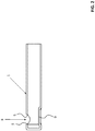
- Fig. 2 shows in a schematic side view, cut, a basic configuration of the outer tube 1, after which it is deformed on the side opposite the side opening 8, namely the in Fig. 2 inner tube 2, not shown, with its cutting edge 4 against the inner cutting edge 5 of the outer tube 1 to press.
- the bias voltage according to the invention can be realized.
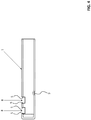
- Fig. 3 shows a further variant of the teaching of the invention, realized by a measure on or in the outer tube 1, similar to the representation in FIG Fig. 2 , Specifically, in the wall of the outer tube 1 a Sike or embossment 9, notch or the like. Provided so that even by this measure, the inner tube 2 with its outer cutting edge 4 and their cutting edges 4, 7 against the inner cutting edge. 5 the outer tube 1 is depressed, namely to promote the cutting result even with considerable play between the inner wall of the outer tube 1 and the outer wall of the inner tube 2.
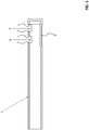
- the outer tube 1 is provided with two lateral openings 8. Accordingly, a plurality of cutting edges 5 are provided, in which in Fig. 4 shown embodiment, a maximum of four cutting edges 5, two for the forward stroke and two for the return stroke.
- An embossment 9 provides the bias with inserted inner tube 2, as in Fig. 1 is shown.
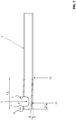
- FIG. 5 is opposite to the representations in the Fig. 2 to 4 mirrored, being opposite to the illustration in Fig. 4 a flat embossment 9 is provided, namely to ensure the bias over the entire distance of the two openings 8 away.
- Fig. 6 shows a further measure for the realization of the bias voltage according to the invention between the outer tube 1 and the inner tube running therein 2.
- the bias voltage is - alternatively or additionally - to the measures according to the Fig. 2 to 5 , realized by a double bend of the inner tube 2 with respect to the longitudinal axis, wherein the two bends of the individual representation of the inner tube 2 according to Fig. 7 are removable.
- a first bend 10 is in the in the Fig. 6 and 7 shown embodiments are provided at 1.6 mm in front of the distal end of the inner tube 2, namely to press the outer cutting edges 4, 7 against the inner wall and the inner cutting edge 5 of the outer tube 1.
- a second bend 11 is provided, which bends the inner tube 2 back at least slightly in flight, so that the outer wall extends approximately parallel to the outer wall before the first bend 10, namely to one strong engagement of the outer cutting edges 4, 7 in the region of the lateral opening 8 of the outer tube 1 to avoid.
- the trained to the distal end second bend 11 is in the in the Fig. 6 and 7 shown embodiments removed about 0.3 mm from the distal end and is provided in the region of the lateral opening 6 of the inner tube 2.
Landscapes
- Health & Medical Sciences (AREA)
- Ophthalmology & Optometry (AREA)
- Life Sciences & Earth Sciences (AREA)
- Surgery (AREA)
- Engineering & Computer Science (AREA)
- Public Health (AREA)
- Heart & Thoracic Surgery (AREA)
- Veterinary Medicine (AREA)
- Nuclear Medicine, Radiotherapy & Molecular Imaging (AREA)
- Animal Behavior & Ethology (AREA)
- General Health & Medical Sciences (AREA)
- Biomedical Technology (AREA)
- Vascular Medicine (AREA)
- Orthopedic Medicine & Surgery (AREA)
- Medical Informatics (AREA)
- Molecular Biology (AREA)
- Surgical Instruments (AREA)
- Prostheses (AREA)
- Endoscopes (AREA)
Claims (14)
- Dispositif de coupe et d'aspiration de tissu du corps humain ou du corps animal, en particulier destiné à être utilisé en vitrectomie ou pour un pelage de la rétine, avec un tube extérieur (1) et un tube intérieur (2) pouvant se déplacer concentriquement dans le tube extérieur (1) dans un mouvement de va-et-vient avec un faible jeu, le tube extérieur (1) étant fermé à l'extrémité libre et présentant près de l'extrémité libre au moins un orifice latéral (8) avec au moins une arête de coupe intérieure (5), le tube intérieur (2) étant ouvert à l'extrémité libre et y présentant une arête de coupe extérieure (4), et les arêtes de coupe coopérant de façon coupante lors du déplacement du tube intérieur (2) par rapport au tube extérieur (1), avec une mesure de mise en forme dans ou respectivement sur le tube intérieur (2), après quoi le tube intérieur (2) court dans le tube extérieur (1) au moins dans la zone de l'orifice latéral (3) en présence d'au moins une faible précontrainte, et le tube intérieur (2) étant courbé ou coudé par rapport à l'axe longitudinal de telle sorte que, lors du déplacement dans un mouvement de va-et-vient du tube intérieur (2) dans le tube extérieur (1), les lames passent l'une devant l'autre en présence d'au moins d'une faible précontrainte, caractérisé en ce que le tube intérieur (2), près de l'extrémité libre ouverte, présente un orifice latéral (6) avec une ou deux arêtes de coupe extérieures (4, 7), et en ce que le tube intérieur (2) est courbé avant l'orifice latéral (6).
- Dispositif selon la revendication 1, caractérisé par une mesure de mise en forme sur le tube extérieur (1), après quoi le tube intérieur (2) court dans le tube extérieur (1) au moins dans la zone de l'orifice latéral (3) en présence d'au moins une faible précontrainte.
- Dispositif selon la revendication 1 ou 2, caractérisé en ce que le tube extérieur (1), près du premier orifice latéral (8), présente un deuxième orifice latéral (8) avec une ou deux arête(s) de coupe intérieure(s) (5).
- Dispositif selon la revendication 3, caractérisé en ce que, entre l'extrémité ouverte et l'orifice latéral (6) du tube intérieur (2), il est constitué uniquement une nervure petite/mince.
- Dispositif selon la revendication 3 ou 4, caractérisé en ce que l'orifice latéral (6) du tube intérieur (2) a au moins la même section transversale d'écoulement que l'extrémité ouverte du tube intérieur (2).
- Dispositif selon l'une des revendications 1 à 5, caractérisé en ce que les orifices (6) dans le tube intérieur (2) ont respectivement à peu près la même section transversale d'écoulement que les orifices (8) dans le tube extérieur (1).
- Dispositif selon l'une des revendications 1 à 6, caractérisé en ce que, en tant que mesure de mise en forme, la paroi intérieure du tube extérieur (1), à peu près en face de l'orifice latéral (8), est constituée de façon saillante vers l'intérieur, ce qui donne une zone de guidage.
- Dispositif selon l'une des revendications 1 à 7, caractérisé en ce que, en tant que mesure de mise en forme, la paroi extérieure du tube intérieur (2), de préférence dans une zone en face de l'orifice latéral (6), est constituée de façon saillante vers l'extérieur, ce qui donne une zone de guidage.
- Dispositif selon la revendication 7 ou 8, caractérisé en ce que, pour le tube extérieur (1), la zone de guidage résulte d'une déformation dirigée de l'extérieur vers l'intérieur et/ou, pour le tube intérieur (2), elle résulte d'une déformation dirigée de l'intérieur vers l'extérieur.
- Dispositif selon la revendication 7 ou 8, caractérisé en ce que, pour le tube extérieur (1), la zone de guidage est réalisée en tant qu'application de matériau côté intérieur et/ou, pour le tube intérieur (2), en tant qu'application de matériau côté extérieur.
- Dispositif selon l'une des revendications 1 à 10, caractérisé en ce que, en tant que mesure de mise en forme, le tube extérieur (1) est, avant l'orifice (8), courbé ou est coudé par rapport à l'axe longitudinal de telle sorte que, lors du déplacement dans un mouvement de va-et-vient du tube intérieur (2) dans le tube extérieur (1), les lames passent l'une devant l'autre en présence d'au moins une faible précontrainte.
- Dispositif selon la revendication 11, caractérisé en ce que le tube intérieur (2) présente deux coudes (10, 11) de même sens ou de sens contraire.
- Dispositif selon la revendication 12, caractérisé en ce que le coude (10) éloigné de l'extrémité libre est compris entre 1° et 2°, et le coude (11) proche de l'extrémité libre est compris entre 2° et 5°.
- Dispositif selon la revendication 12 ou 13, caractérisé en ce que le coude (10) éloigné de l'extrémité libre est situé entre 1 mm et 2 mm avant l'extrémité libre, et le coude (11) proche de l'extrémité libre est situé dans la zone de l'orifice latéral (6) du tube intérieur (2), de préférence entre 0,1 mm et 0,5 mm avant l'extrémité libre.
Applications Claiming Priority (2)
| Application Number | Priority Date | Filing Date | Title |
|---|---|---|---|
| DE102013201784.7A DE102013201784B4 (de) | 2013-02-04 | 2013-02-04 | Vorrichtung zum Schneiden und Absaugen von Gewebe |
| PCT/DE2014/200007 WO2014117774A1 (fr) | 2013-02-04 | 2014-01-20 | Dispositif de coupe et d'aspiration de tissu |
Publications (2)
| Publication Number | Publication Date |
|---|---|
| EP2802303A1 EP2802303A1 (fr) | 2014-11-19 |
| EP2802303B1 true EP2802303B1 (fr) | 2018-04-04 |
Family
ID=50184704
Family Applications (1)
| Application Number | Title | Priority Date | Filing Date |
|---|---|---|---|
| EP14706773.0A Active EP2802303B1 (fr) | 2013-02-04 | 2014-01-20 | Dispositif de coupe et d'aspiration de tissu |
Country Status (5)
| Country | Link |
|---|---|
| US (1) | US9956115B2 (fr) |
| EP (1) | EP2802303B1 (fr) |
| CN (1) | CN104968307B (fr) |
| DE (1) | DE102013201784B4 (fr) |
| WO (1) | WO2014117774A1 (fr) |
Families Citing this family (23)
| Publication number | Priority date | Publication date | Assignee | Title |
|---|---|---|---|---|
| US9615969B2 (en) | 2012-12-18 | 2017-04-11 | Novartis Ag | Multi-port vitrectomy probe with dual cutting edges |
| NL2010444C2 (nl) * | 2013-03-13 | 2014-09-16 | D O R C Dutch Ophthalmic Res Ct International B V | Oogchirurgisch snijgereedschap. |
| DE102014219616A1 (de) | 2014-09-26 | 2016-03-31 | Geuder Ag | Vorrichtung zum Schneiden von Gewebe |
| US9693898B2 (en) | 2014-11-19 | 2017-07-04 | Novartis Ag | Double-acting vitreous probe with contoured port |
| US10398813B2 (en) * | 2015-02-27 | 2019-09-03 | Marcos Sforza | Harvesting cannula |
| US9707012B2 (en) * | 2015-07-31 | 2017-07-18 | Polygon Medical, Inc. | Polypectomy systems, devices, and methods |
| US10933544B2 (en) * | 2015-12-17 | 2021-03-02 | Todd Schwartz | Guillotine style cutting mechanism |
| EP4005512B1 (fr) * | 2016-07-14 | 2024-08-14 | Stryker European Operations Holdings LLC | Ensemble de coupe pour un instrument chirurgical doté d'un ensemble d'entraînement |
| US20180104101A1 (en) * | 2016-10-19 | 2018-04-19 | Novartis Ag | Formed cutter for vitrectomy probe |
| US10285731B2 (en) | 2017-06-14 | 2019-05-14 | Polygon Medical, Inc. | Polypectomy systems, devices, and methods |
| US10639197B2 (en) | 2017-06-19 | 2020-05-05 | Alcon Inc. | Vitrectomy probe |
| USD847992S1 (en) | 2017-06-27 | 2019-05-07 | Polygon Medical, Inc. | Medical device handle |
| DE102017221017A1 (de) | 2017-11-24 | 2019-05-29 | Geuder Ag | Vorrichtung zum Schneiden und Absaugen von Gewebe aus dem menschlichen oder tierischen Auge |
| CN107998472A (zh) * | 2017-12-28 | 2018-05-08 | 山西阳光中天医疗器械有限公司 | 一种双套式自动吸脂针管及其吸脂方法 |
| WO2019172893A1 (fr) * | 2018-03-06 | 2019-09-12 | 32986.00 Patent Application Trust | Dispositif de coupe de vitrectomie à orifices multiples |
| US11826068B2 (en) | 2018-12-10 | 2023-11-28 | Acclarent, Inc. | Method of forming suction instrument end and shaver instrument end |
| CN109770999B (zh) * | 2019-01-28 | 2024-04-16 | 逸思(苏州)医疗科技有限公司 | 一种手术切割器 |
| DE102019206871B4 (de) * | 2019-05-07 | 2023-07-20 | Geuder Ag | Vorrichtung zum Schneiden und Absaugen von Gewebe aus dem menschlichen oder tierischen Auge |
| CN112587301B (zh) * | 2020-12-27 | 2023-01-17 | 河南科技大学第一附属医院 | 一种双管式眼科玻璃体切除用玻切头 |
| CN113288239B (zh) * | 2021-06-02 | 2022-12-02 | 邵明星 | 一种医用骨科临床用游离体取出器 |
| CN114949391B (zh) * | 2022-05-24 | 2024-01-26 | 四川大学华西医院 | 一种消化道内潴留物清除装置 |
| CN115350000A (zh) * | 2022-09-21 | 2022-11-18 | 微创视神医疗科技(上海)有限公司 | 一种探针 |
| CN118058866B (zh) * | 2024-03-04 | 2024-10-08 | 山东省动物疫病预防与控制中心(山东省人畜共患病流调监测中心) | 一种肉鸭基因筛选采集器 |
Family Cites Families (19)
| Publication number | Priority date | Publication date | Assignee | Title |
|---|---|---|---|---|
| US4011869A (en) * | 1975-08-01 | 1977-03-15 | David Kopf Instruments | Tubular cutting instrument |
| US4111207A (en) | 1976-10-28 | 1978-09-05 | David Kopf Instruments | Notched tubular cutting instrument |
| US4513745A (en) * | 1978-06-21 | 1985-04-30 | Amoils Selig P | Surgical instruments and methods particularly adapted for intra-ocular cutting and the like |
| US4696298A (en) * | 1985-11-19 | 1987-09-29 | Storz Instrument Company | Vitrectomy cutting mechanism |
| US5106364A (en) * | 1989-07-07 | 1992-04-21 | Kabushiki Kaisha Topcon | Surgical cutter |
| US5314440A (en) * | 1992-11-02 | 1994-05-24 | Henry Shapiro | Microsurgical scissor apparatus |
| US5458112A (en) * | 1994-08-15 | 1995-10-17 | Arrow Precision Products, Inc. | Biliary biopsy device |
| US5474532A (en) | 1994-11-22 | 1995-12-12 | Alcon Laboratories, Inc. | Cutting blade for a vitreous cutter |
| US5843111A (en) * | 1995-06-19 | 1998-12-01 | Ophthalmic Research Center International Bv | Vitreous removing apparatus |
| US5630827A (en) * | 1995-06-19 | 1997-05-20 | Dutch Ophthalmic Research Center International Bv | Vitreous removing apparatus |
| US6258111B1 (en) * | 1997-10-03 | 2001-07-10 | Scieran Technologies, Inc. | Apparatus and method for performing ophthalmic procedures |
| US5911701A (en) * | 1998-01-29 | 1999-06-15 | Sdgi Holidings, Inc. | Surgical cutting instrument |
| US6695821B1 (en) * | 1998-06-17 | 2004-02-24 | Raymond N. Sjaarda | Surgical infusion tool with flow diffuser |
| US7744583B2 (en) * | 2003-02-03 | 2010-06-29 | Boston Scientific Scimed | Systems and methods of de-endothelialization |
| WO2009036383A1 (fr) * | 2007-09-12 | 2009-03-19 | Promex Technologies, Llc | Instrument chirurgical coupant |
| DE102010050337A1 (de) | 2010-11-05 | 2012-05-10 | Volker Geuder | Vorrichtung zum Schneiden und Absaugen von Gewebe |
| CH704384B1 (de) * | 2011-01-25 | 2014-09-30 | Bürki Inno Med Ag | Chirurgisches Schneidinstrument. |
| EP2617363B1 (fr) * | 2011-07-06 | 2015-09-16 | Olympus Medical Systems Corp. | Instrument de traitement et de collecte d'échantillons |
| US9615969B2 (en) * | 2012-12-18 | 2017-04-11 | Novartis Ag | Multi-port vitrectomy probe with dual cutting edges |
-
2013
- 2013-02-04 DE DE102013201784.7A patent/DE102013201784B4/de active Active
-
2014
- 2014-01-20 CN CN201480007279.4A patent/CN104968307B/zh active Active
- 2014-01-20 WO PCT/DE2014/200007 patent/WO2014117774A1/fr not_active Ceased
- 2014-01-20 US US14/759,350 patent/US9956115B2/en active Active
- 2014-01-20 EP EP14706773.0A patent/EP2802303B1/fr active Active
Also Published As
| Publication number | Publication date |
|---|---|
| US20150335485A1 (en) | 2015-11-26 |
| CN104968307B (zh) | 2019-01-11 |
| WO2014117774A1 (fr) | 2014-08-07 |
| EP2802303A1 (fr) | 2014-11-19 |
| CN104968307A (zh) | 2015-10-07 |
| DE102013201784B4 (de) | 2015-05-28 |
| DE102013201784A1 (de) | 2014-08-07 |
| US9956115B2 (en) | 2018-05-01 |
Similar Documents
| Publication | Publication Date | Title |
|---|---|---|
| EP2802303B1 (fr) | Dispositif de coupe et d'aspiration de tissu | |
| EP2521518B1 (fr) | Dispositif pour couper et aspirer des tissus | |
| EP3041443B1 (fr) | Instrument chirurgical | |
| DE202004015990U1 (de) | Chirurgisches Stanzinstrument | |
| EP2996585B1 (fr) | Instrument chirurgical | |
| EP3013289B1 (fr) | Dispositif de coupe de tissus | |
| EP3488835B1 (fr) | Dispositif de coupe et d'aspiration de tissu de l'oeil humain ou animal | |
| DE202013012000U1 (de) | Vorrichtung zum Schneiden und Absaugen von Gewebe | |
| DE102008023967A1 (de) | Hohlnadel für ein augenchirurgisches Instrument | |
| DE102014207971A1 (de) | Maulteil mit Schichtaufbau für ein chirurgisches Instrument | |
| CH704384A2 (de) | Chirurgisches Schneidinstrument. | |
| DE102019206871B4 (de) | Vorrichtung zum Schneiden und Absaugen von Gewebe aus dem menschlichen oder tierischen Auge | |
| DE202009001829U1 (de) | Chirurgisches Schiebeschaftinstrument und Schiebeschaft | |
| EP2889007A1 (fr) | Instrument destiné à maintenir le sternum ouvert | |
| DE102014104146A1 (de) | Stanze | |
| DE102012209247A1 (de) | Chirurgisches Schiebeschaftinstrument | |
| DE102012107261B4 (de) | Medizinische Vorrichtung zur Einfuhr in einen lebenden Körper und Verfahren zum Herstellen einer derartigen Vorrichtung | |
| EP3064250A1 (fr) | Auto-piqueur et piqueur destiné au perçage local d'une peau humaine ou animale et agencement d'auto-piqueur | |
| DE102007002486A1 (de) | Applikator für das chirurgische Wasserstrahltrennen zur Erzeugung eines Flachstrahls und Verfahren zur Herstellung des Applikators | |
| DE102015219062A1 (de) | Hohlnadel für ein augenchirurgisches Instrument | |
| DE102022204957A1 (de) | Ophthalmologisches Handgerät und Verfahren zum Einstellen eines ophthalmologischen Handgeräts | |
| WO2022073817A1 (fr) | Instrument chirurgical à main de type à tige | |
| DE102009008691A1 (de) | Chirurgisches Schiebeschaftinstrument und Schiebeschaft | |
| DE102017209595A1 (de) | Hohlnadel für ein augenchirurgisches Instrument | |
| DE102012106762A1 (de) | Applikator für Kosmetika und Herstellungsverfahren dafür |
Legal Events
| Date | Code | Title | Description |
|---|---|---|---|
| PUAI | Public reference made under article 153(3) epc to a published international application that has entered the european phase |
Free format text: ORIGINAL CODE: 0009012 |
|
| 17P | Request for examination filed |
Effective date: 20140813 |
|
| AK | Designated contracting states |
Kind code of ref document: A1 Designated state(s): AL AT BE BG CH CY CZ DE DK EE ES FI FR GB GR HR HU IE IS IT LI LT LU LV MC MK MT NL NO PL PT RO RS SE SI SK SM TR |
|
| RIN1 | Information on inventor provided before grant (corrected) |
Inventor name: DRAHEIM, RENE Inventor name: FRAUENFELD, DIETER Inventor name: GEUDER, VOLKER Inventor name: RIEGER, FRANK |
|
| DAX | Request for extension of the european patent (deleted) | ||
| STAA | Information on the status of an ep patent application or granted ep patent |
Free format text: STATUS: EXAMINATION IS IN PROGRESS |
|
| 17Q | First examination report despatched |
Effective date: 20170719 |
|
| GRAP | Despatch of communication of intention to grant a patent |
Free format text: ORIGINAL CODE: EPIDOSNIGR1 |
|
| STAA | Information on the status of an ep patent application or granted ep patent |
Free format text: STATUS: GRANT OF PATENT IS INTENDED |
|
| INTG | Intention to grant announced |
Effective date: 20180115 |
|
| GRAS | Grant fee paid |
Free format text: ORIGINAL CODE: EPIDOSNIGR3 |
|
| GRAA | (expected) grant |
Free format text: ORIGINAL CODE: 0009210 |
|
| STAA | Information on the status of an ep patent application or granted ep patent |
Free format text: STATUS: THE PATENT HAS BEEN GRANTED |
|
| AK | Designated contracting states |
Kind code of ref document: B1 Designated state(s): AL AT BE BG CH CY CZ DE DK EE ES FI FR GB GR HR HU IE IS IT LI LT LU LV MC MK MT NL NO PL PT RO RS SE SI SK SM TR |
|
| REG | Reference to a national code |
Ref country code: GB Ref legal event code: FG4D Free format text: NOT ENGLISH |
|
| REG | Reference to a national code |
Ref country code: CH Ref legal event code: EP |
|
| REG | Reference to a national code |
Ref country code: AT Ref legal event code: REF Ref document number: 984759 Country of ref document: AT Kind code of ref document: T Effective date: 20180415 |
|
| REG | Reference to a national code |
Ref country code: IE Ref legal event code: FG4D Free format text: LANGUAGE OF EP DOCUMENT: GERMAN |
|
| REG | Reference to a national code |
Ref country code: DE Ref legal event code: R096 Ref document number: 502014007839 Country of ref document: DE |
|
| REG | Reference to a national code |
Ref country code: NL Ref legal event code: FP |
|
| REG | Reference to a national code |
Ref country code: LT Ref legal event code: MG4D |
|
| PG25 | Lapsed in a contracting state [announced via postgrant information from national office to epo] |
Ref country code: AL Free format text: LAPSE BECAUSE OF FAILURE TO SUBMIT A TRANSLATION OF THE DESCRIPTION OR TO PAY THE FEE WITHIN THE PRESCRIBED TIME-LIMIT Effective date: 20180404 Ref country code: FI Free format text: LAPSE BECAUSE OF FAILURE TO SUBMIT A TRANSLATION OF THE DESCRIPTION OR TO PAY THE FEE WITHIN THE PRESCRIBED TIME-LIMIT Effective date: 20180404 Ref country code: BG Free format text: LAPSE BECAUSE OF FAILURE TO SUBMIT A TRANSLATION OF THE DESCRIPTION OR TO PAY THE FEE WITHIN THE PRESCRIBED TIME-LIMIT Effective date: 20180704 Ref country code: LT Free format text: LAPSE BECAUSE OF FAILURE TO SUBMIT A TRANSLATION OF THE DESCRIPTION OR TO PAY THE FEE WITHIN THE PRESCRIBED TIME-LIMIT Effective date: 20180404 Ref country code: SE Free format text: LAPSE BECAUSE OF FAILURE TO SUBMIT A TRANSLATION OF THE DESCRIPTION OR TO PAY THE FEE WITHIN THE PRESCRIBED TIME-LIMIT Effective date: 20180404 Ref country code: NO Free format text: LAPSE BECAUSE OF FAILURE TO SUBMIT A TRANSLATION OF THE DESCRIPTION OR TO PAY THE FEE WITHIN THE PRESCRIBED TIME-LIMIT Effective date: 20180704 Ref country code: PL Free format text: LAPSE BECAUSE OF FAILURE TO SUBMIT A TRANSLATION OF THE DESCRIPTION OR TO PAY THE FEE WITHIN THE PRESCRIBED TIME-LIMIT Effective date: 20180404 |
|
| PG25 | Lapsed in a contracting state [announced via postgrant information from national office to epo] |
Ref country code: RS Free format text: LAPSE BECAUSE OF FAILURE TO SUBMIT A TRANSLATION OF THE DESCRIPTION OR TO PAY THE FEE WITHIN THE PRESCRIBED TIME-LIMIT Effective date: 20180404 Ref country code: LV Free format text: LAPSE BECAUSE OF FAILURE TO SUBMIT A TRANSLATION OF THE DESCRIPTION OR TO PAY THE FEE WITHIN THE PRESCRIBED TIME-LIMIT Effective date: 20180404 Ref country code: GR Free format text: LAPSE BECAUSE OF FAILURE TO SUBMIT A TRANSLATION OF THE DESCRIPTION OR TO PAY THE FEE WITHIN THE PRESCRIBED TIME-LIMIT Effective date: 20180705 Ref country code: HR Free format text: LAPSE BECAUSE OF FAILURE TO SUBMIT A TRANSLATION OF THE DESCRIPTION OR TO PAY THE FEE WITHIN THE PRESCRIBED TIME-LIMIT Effective date: 20180404 |
|
| PG25 | Lapsed in a contracting state [announced via postgrant information from national office to epo] |
Ref country code: PT Free format text: LAPSE BECAUSE OF FAILURE TO SUBMIT A TRANSLATION OF THE DESCRIPTION OR TO PAY THE FEE WITHIN THE PRESCRIBED TIME-LIMIT Effective date: 20180806 |
|
| REG | Reference to a national code |
Ref country code: DE Ref legal event code: R097 Ref document number: 502014007839 Country of ref document: DE |
|
| PG25 | Lapsed in a contracting state [announced via postgrant information from national office to epo] |
Ref country code: SK Free format text: LAPSE BECAUSE OF FAILURE TO SUBMIT A TRANSLATION OF THE DESCRIPTION OR TO PAY THE FEE WITHIN THE PRESCRIBED TIME-LIMIT Effective date: 20180404 Ref country code: EE Free format text: LAPSE BECAUSE OF FAILURE TO SUBMIT A TRANSLATION OF THE DESCRIPTION OR TO PAY THE FEE WITHIN THE PRESCRIBED TIME-LIMIT Effective date: 20180404 Ref country code: RO Free format text: LAPSE BECAUSE OF FAILURE TO SUBMIT A TRANSLATION OF THE DESCRIPTION OR TO PAY THE FEE WITHIN THE PRESCRIBED TIME-LIMIT Effective date: 20180404 Ref country code: CZ Free format text: LAPSE BECAUSE OF FAILURE TO SUBMIT A TRANSLATION OF THE DESCRIPTION OR TO PAY THE FEE WITHIN THE PRESCRIBED TIME-LIMIT Effective date: 20180404 Ref country code: DK Free format text: LAPSE BECAUSE OF FAILURE TO SUBMIT A TRANSLATION OF THE DESCRIPTION OR TO PAY THE FEE WITHIN THE PRESCRIBED TIME-LIMIT Effective date: 20180404 |
|
| PLBE | No opposition filed within time limit |
Free format text: ORIGINAL CODE: 0009261 |
|
| STAA | Information on the status of an ep patent application or granted ep patent |
Free format text: STATUS: NO OPPOSITION FILED WITHIN TIME LIMIT |
|
| PG25 | Lapsed in a contracting state [announced via postgrant information from national office to epo] |
Ref country code: SM Free format text: LAPSE BECAUSE OF FAILURE TO SUBMIT A TRANSLATION OF THE DESCRIPTION OR TO PAY THE FEE WITHIN THE PRESCRIBED TIME-LIMIT Effective date: 20180404 |
|
| 26N | No opposition filed |
Effective date: 20190107 |
|
| PG25 | Lapsed in a contracting state [announced via postgrant information from national office to epo] |
Ref country code: SI Free format text: LAPSE BECAUSE OF FAILURE TO SUBMIT A TRANSLATION OF THE DESCRIPTION OR TO PAY THE FEE WITHIN THE PRESCRIBED TIME-LIMIT Effective date: 20180404 |
|
| PG25 | Lapsed in a contracting state [announced via postgrant information from national office to epo] |
Ref country code: ES Free format text: LAPSE BECAUSE OF FAILURE TO SUBMIT A TRANSLATION OF THE DESCRIPTION OR TO PAY THE FEE WITHIN THE PRESCRIBED TIME-LIMIT Effective date: 20180404 |
|
| PG25 | Lapsed in a contracting state [announced via postgrant information from national office to epo] |
Ref country code: MC Free format text: LAPSE BECAUSE OF FAILURE TO SUBMIT A TRANSLATION OF THE DESCRIPTION OR TO PAY THE FEE WITHIN THE PRESCRIBED TIME-LIMIT Effective date: 20180404 |
|
| PG25 | Lapsed in a contracting state [announced via postgrant information from national office to epo] |
Ref country code: LU Free format text: LAPSE BECAUSE OF NON-PAYMENT OF DUE FEES Effective date: 20190120 |
|
| REG | Reference to a national code |
Ref country code: BE Ref legal event code: MM Effective date: 20190131 |
|
| REG | Reference to a national code |
Ref country code: IE Ref legal event code: MM4A |
|
| PG25 | Lapsed in a contracting state [announced via postgrant information from national office to epo] |
Ref country code: BE Free format text: LAPSE BECAUSE OF NON-PAYMENT OF DUE FEES Effective date: 20190131 |
|
| PG25 | Lapsed in a contracting state [announced via postgrant information from national office to epo] |
Ref country code: IE Free format text: LAPSE BECAUSE OF NON-PAYMENT OF DUE FEES Effective date: 20190120 |
|
| PG25 | Lapsed in a contracting state [announced via postgrant information from national office to epo] |
Ref country code: TR Free format text: LAPSE BECAUSE OF FAILURE TO SUBMIT A TRANSLATION OF THE DESCRIPTION OR TO PAY THE FEE WITHIN THE PRESCRIBED TIME-LIMIT Effective date: 20180404 |
|
| PG25 | Lapsed in a contracting state [announced via postgrant information from national office to epo] |
Ref country code: MT Free format text: LAPSE BECAUSE OF FAILURE TO SUBMIT A TRANSLATION OF THE DESCRIPTION OR TO PAY THE FEE WITHIN THE PRESCRIBED TIME-LIMIT Effective date: 20180404 |
|
| PG25 | Lapsed in a contracting state [announced via postgrant information from national office to epo] |
Ref country code: CY Free format text: LAPSE BECAUSE OF FAILURE TO SUBMIT A TRANSLATION OF THE DESCRIPTION OR TO PAY THE FEE WITHIN THE PRESCRIBED TIME-LIMIT Effective date: 20180404 |
|
| PG25 | Lapsed in a contracting state [announced via postgrant information from national office to epo] |
Ref country code: IS Free format text: LAPSE BECAUSE OF FAILURE TO SUBMIT A TRANSLATION OF THE DESCRIPTION OR TO PAY THE FEE WITHIN THE PRESCRIBED TIME-LIMIT Effective date: 20180804 |
|
| PG25 | Lapsed in a contracting state [announced via postgrant information from national office to epo] |
Ref country code: HU Free format text: LAPSE BECAUSE OF FAILURE TO SUBMIT A TRANSLATION OF THE DESCRIPTION OR TO PAY THE FEE WITHIN THE PRESCRIBED TIME-LIMIT; INVALID AB INITIO Effective date: 20140120 |
|
| PG25 | Lapsed in a contracting state [announced via postgrant information from national office to epo] |
Ref country code: MK Free format text: LAPSE BECAUSE OF FAILURE TO SUBMIT A TRANSLATION OF THE DESCRIPTION OR TO PAY THE FEE WITHIN THE PRESCRIBED TIME-LIMIT Effective date: 20180404 |
|
| P01 | Opt-out of the competence of the unified patent court (upc) registered |
Effective date: 20230525 |
|
| PGFP | Annual fee paid to national office [announced via postgrant information from national office to epo] |
Ref country code: DE Payment date: 20250430 Year of fee payment: 12 |
|
| REG | Reference to a national code |
Ref country code: CH Ref legal event code: U11 Free format text: ST27 STATUS EVENT CODE: U-0-0-U10-U11 (AS PROVIDED BY THE NATIONAL OFFICE) Effective date: 20260201 |
|
| PGFP | Annual fee paid to national office [announced via postgrant information from national office to epo] |
Ref country code: NL Payment date: 20260121 Year of fee payment: 13 |
|
| PGFP | Annual fee paid to national office [announced via postgrant information from national office to epo] |
Ref country code: GB Payment date: 20260122 Year of fee payment: 13 |
|
| PGFP | Annual fee paid to national office [announced via postgrant information from national office to epo] |
Ref country code: AT Payment date: 20260119 Year of fee payment: 13 |
|
| PGFP | Annual fee paid to national office [announced via postgrant information from national office to epo] |
Ref country code: IT Payment date: 20260130 Year of fee payment: 13 |
|
| PGFP | Annual fee paid to national office [announced via postgrant information from national office to epo] |
Ref country code: FR Payment date: 20260123 Year of fee payment: 13 |
|
| PGFP | Annual fee paid to national office [announced via postgrant information from national office to epo] |
Ref country code: CH Payment date: 20260201 Year of fee payment: 13 |