EP2802491B1 - Vorrichtung zum installieren und deinstallieren einer fahrzeugbatterie - Google Patents
Vorrichtung zum installieren und deinstallieren einer fahrzeugbatterie Download PDFInfo
- Publication number
- EP2802491B1 EP2802491B1 EP12816768.1A EP12816768A EP2802491B1 EP 2802491 B1 EP2802491 B1 EP 2802491B1 EP 12816768 A EP12816768 A EP 12816768A EP 2802491 B1 EP2802491 B1 EP 2802491B1
- Authority
- EP
- European Patent Office
- Prior art keywords
- vehicle
- battery
- cables
- underside
- relative
- Prior art date
- Legal status (The legal status is an assumption and is not a legal conclusion. Google has not performed a legal analysis and makes no representation as to the accuracy of the status listed.)
- Not-in-force
Links
- 230000007246 mechanism Effects 0.000 claims description 13
- 238000012937 correction Methods 0.000 claims description 8
- 238000006073 displacement reaction Methods 0.000 description 20
- 230000003993 interaction Effects 0.000 description 16
- 238000005096 rolling process Methods 0.000 description 10
- 210000004027 cell Anatomy 0.000 description 7
- 230000008901 benefit Effects 0.000 description 5
- 238000013461 design Methods 0.000 description 4
- 238000009434 installation Methods 0.000 description 3
- 238000012546 transfer Methods 0.000 description 3
- 238000013519 translation Methods 0.000 description 3
- 230000009471 action Effects 0.000 description 2
- 230000008859 change Effects 0.000 description 2
- 230000000295 complement effect Effects 0.000 description 2
- 238000000034 method Methods 0.000 description 2
- 210000000352 storage cell Anatomy 0.000 description 2
- 238000006467 substitution reaction Methods 0.000 description 2
- 229910000831 Steel Inorganic materials 0.000 description 1
- 238000013459 approach Methods 0.000 description 1
- 238000004140 cleaning Methods 0.000 description 1
- 238000011161 development Methods 0.000 description 1
- 230000003028 elevating effect Effects 0.000 description 1
- 230000003100 immobilizing effect Effects 0.000 description 1
- 239000010959 steel Substances 0.000 description 1
Images


Classifications
-
- B—PERFORMING OPERATIONS; TRANSPORTING
- B60—VEHICLES IN GENERAL
- B60K—ARRANGEMENT OR MOUNTING OF PROPULSION UNITS OR OF TRANSMISSIONS IN VEHICLES; ARRANGEMENT OR MOUNTING OF PLURAL DIVERSE PRIME-MOVERS IN VEHICLES; AUXILIARY DRIVES FOR VEHICLES; INSTRUMENTATION OR DASHBOARDS FOR VEHICLES; ARRANGEMENTS IN CONNECTION WITH COOLING, AIR INTAKE, GAS EXHAUST OR FUEL SUPPLY OF PROPULSION UNITS IN VEHICLES
- B60K1/00—Arrangement or mounting of electrical propulsion units
- B60K1/04—Arrangement or mounting of electrical propulsion units of the electric storage means for propulsion
-
- B—PERFORMING OPERATIONS; TRANSPORTING
- B60—VEHICLES IN GENERAL
- B60L—PROPULSION OF ELECTRICALLY-PROPELLED VEHICLES; SUPPLYING ELECTRIC POWER FOR AUXILIARY EQUIPMENT OF ELECTRICALLY-PROPELLED VEHICLES; ELECTRODYNAMIC BRAKE SYSTEMS FOR VEHICLES IN GENERAL; MAGNETIC SUSPENSION OR LEVITATION FOR VEHICLES; MONITORING OPERATING VARIABLES OF ELECTRICALLY-PROPELLED VEHICLES; ELECTRIC SAFETY DEVICES FOR ELECTRICALLY-PROPELLED VEHICLES
- B60L53/00—Methods of charging batteries, specially adapted for electric vehicles; Charging stations or on-board charging equipment therefor; Exchange of energy storage elements in electric vehicles
- B60L53/80—Exchanging energy storage elements, e.g. removable batteries
-
- B—PERFORMING OPERATIONS; TRANSPORTING
- B60—VEHICLES IN GENERAL
- B60S—SERVICING, CLEANING, REPAIRING, SUPPORTING, LIFTING, OR MANOEUVRING OF VEHICLES, NOT OTHERWISE PROVIDED FOR
- B60S5/00—Servicing, maintaining, repairing, or refitting of vehicles
- B60S5/06—Supplying batteries to, or removing batteries from, vehicles
-
- B—PERFORMING OPERATIONS; TRANSPORTING
- B60—VEHICLES IN GENERAL
- B60K—ARRANGEMENT OR MOUNTING OF PROPULSION UNITS OR OF TRANSMISSIONS IN VEHICLES; ARRANGEMENT OR MOUNTING OF PLURAL DIVERSE PRIME-MOVERS IN VEHICLES; AUXILIARY DRIVES FOR VEHICLES; INSTRUMENTATION OR DASHBOARDS FOR VEHICLES; ARRANGEMENTS IN CONNECTION WITH COOLING, AIR INTAKE, GAS EXHAUST OR FUEL SUPPLY OF PROPULSION UNITS IN VEHICLES
- B60K1/00—Arrangement or mounting of electrical propulsion units
- B60K1/04—Arrangement or mounting of electrical propulsion units of the electric storage means for propulsion
- B60K2001/0455—Removal or replacement of the energy storages
- B60K2001/0472—Removal or replacement of the energy storages from below
-
- B—PERFORMING OPERATIONS; TRANSPORTING
- B60—VEHICLES IN GENERAL
- B60Y—INDEXING SCHEME RELATING TO ASPECTS CROSS-CUTTING VEHICLE TECHNOLOGY
- B60Y2200/00—Type of vehicle
- B60Y2200/90—Vehicles comprising electric prime movers
- B60Y2200/91—Electric vehicles
-
- B—PERFORMING OPERATIONS; TRANSPORTING
- B60—VEHICLES IN GENERAL
- B60Y—INDEXING SCHEME RELATING TO ASPECTS CROSS-CUTTING VEHICLE TECHNOLOGY
- B60Y2200/00—Type of vehicle
- B60Y2200/90—Vehicles comprising electric prime movers
- B60Y2200/92—Hybrid vehicles
-
- Y—GENERAL TAGGING OF NEW TECHNOLOGICAL DEVELOPMENTS; GENERAL TAGGING OF CROSS-SECTIONAL TECHNOLOGIES SPANNING OVER SEVERAL SECTIONS OF THE IPC; TECHNICAL SUBJECTS COVERED BY FORMER USPC CROSS-REFERENCE ART COLLECTIONS [XRACs] AND DIGESTS
- Y02—TECHNOLOGIES OR APPLICATIONS FOR MITIGATION OR ADAPTATION AGAINST CLIMATE CHANGE
- Y02T—CLIMATE CHANGE MITIGATION TECHNOLOGIES RELATED TO TRANSPORTATION
- Y02T10/00—Road transport of goods or passengers
- Y02T10/60—Other road transportation technologies with climate change mitigation effect
- Y02T10/70—Energy storage systems for electromobility, e.g. batteries
-
- Y—GENERAL TAGGING OF NEW TECHNOLOGICAL DEVELOPMENTS; GENERAL TAGGING OF CROSS-SECTIONAL TECHNOLOGIES SPANNING OVER SEVERAL SECTIONS OF THE IPC; TECHNICAL SUBJECTS COVERED BY FORMER USPC CROSS-REFERENCE ART COLLECTIONS [XRACs] AND DIGESTS
- Y02—TECHNOLOGIES OR APPLICATIONS FOR MITIGATION OR ADAPTATION AGAINST CLIMATE CHANGE
- Y02T—CLIMATE CHANGE MITIGATION TECHNOLOGIES RELATED TO TRANSPORTATION
- Y02T10/00—Road transport of goods or passengers
- Y02T10/60—Other road transportation technologies with climate change mitigation effect
- Y02T10/7072—Electromobility specific charging systems or methods for batteries, ultracapacitors, supercapacitors or double-layer capacitors
-
- Y—GENERAL TAGGING OF NEW TECHNOLOGICAL DEVELOPMENTS; GENERAL TAGGING OF CROSS-SECTIONAL TECHNOLOGIES SPANNING OVER SEVERAL SECTIONS OF THE IPC; TECHNICAL SUBJECTS COVERED BY FORMER USPC CROSS-REFERENCE ART COLLECTIONS [XRACs] AND DIGESTS
- Y02—TECHNOLOGIES OR APPLICATIONS FOR MITIGATION OR ADAPTATION AGAINST CLIMATE CHANGE
- Y02T—CLIMATE CHANGE MITIGATION TECHNOLOGIES RELATED TO TRANSPORTATION
- Y02T90/00—Enabling technologies or technologies with a potential or indirect contribution to GHG emissions mitigation
- Y02T90/10—Technologies relating to charging of electric vehicles
- Y02T90/12—Electric charging stations
-
- Y—GENERAL TAGGING OF NEW TECHNOLOGICAL DEVELOPMENTS; GENERAL TAGGING OF CROSS-SECTIONAL TECHNOLOGIES SPANNING OVER SEVERAL SECTIONS OF THE IPC; TECHNICAL SUBJECTS COVERED BY FORMER USPC CROSS-REFERENCE ART COLLECTIONS [XRACs] AND DIGESTS
- Y10—TECHNICAL SUBJECTS COVERED BY FORMER USPC
- Y10T—TECHNICAL SUBJECTS COVERED BY FORMER US CLASSIFICATION
- Y10T29/00—Metal working
- Y10T29/53—Means to assemble or disassemble
- Y10T29/5313—Means to assemble electrical device
-
- Y—GENERAL TAGGING OF NEW TECHNOLOGICAL DEVELOPMENTS; GENERAL TAGGING OF CROSS-SECTIONAL TECHNOLOGIES SPANNING OVER SEVERAL SECTIONS OF THE IPC; TECHNICAL SUBJECTS COVERED BY FORMER USPC CROSS-REFERENCE ART COLLECTIONS [XRACs] AND DIGESTS
- Y10—TECHNICAL SUBJECTS COVERED BY FORMER USPC
- Y10T—TECHNICAL SUBJECTS COVERED BY FORMER US CLASSIFICATION
- Y10T29/00—Metal working
- Y10T29/53—Means to assemble or disassemble
- Y10T29/53274—Means to disassemble electrical device
Definitions
- the invention relates to the field of the exchange of a power supply battery of an electric traction motor of a vehicle of all-electric type or hybrid type.
- the invention more particularly relates to a device for mounting and dismounting such a battery on a vehicle.
- Some motor vehicles such as electric or hybrid vehicles, include a power supply container of an electric drive type electric battery drive motor.
- battery will be used for the sake of simplification, as broadly defined as any electrical power supply container of an electric drive motor of a vehicle. It may be interesting to exchange this battery when its energy level is low against a new charged battery. This can be done in an exchange station, such as a station similar to a service station for filling tanks associated with the engines.
- Document is known US2010 / 145717 an electric battery exchange station supplying an electric drive motor of an electric vehicle and a method for performing such an exchange.
- the exchange station described comprises a lifting table carrying a locking element and unlocking the battery on the vehicle.
- a difficulty for the implementation of such a battery exchange concept lies in the fact that there is a multitude of motor vehicles that can include batteries of different types, fixed in different ways on the motor vehicle. However, it is not economically feasible to multiply the mounting and dismounting systems of these different types of batteries or to set up a manual solution because of its cost and the weight of the batteries.
- the solution described in the document US2010 / 145717 does not respond satisfactorily to this problem of flexibility of the battery exchange solution due in particular to a lack of robustness.
- the object of the present invention is to provide a solution for exchanging a battery for powering an electric traction motor of an all-electric or hybrid-type vehicle that responds to these problems.
- a device for mounting and dismounting a battery below an electric or hybrid vehicle the underside of the vehicle being disposed in a substantially horizontal first plane
- the device comprising a lift table vertically moving a body of interaction able to interact with the underside of the vehicle.
- the interaction member is brought by the lifting table into mechanical contact with the underside of the vehicle, the top of the member being then disposed in a second substantially horizontal plane in a state that does not allow said member to interact with the underside. of the vehicle because of a relative inclination between the first and the second plane.
- the lift table is lifted by means of at least two cables whose elasticity makes it possible to compensate the relative inclination of the two planes in order to allow the body to interact with the underside of the vehicle.
- the elasticity of the cables may make it possible to compensate for the relative inclination of the two planes in the limit of the deformability of said cables.
- the cables can be arranged symmetrically on either side of the lifting table, be driven by the same motor and / or by means of pulleys.
- the device may further comprise a trim element for setting the vehicle in the substantially horizontal first plane.
- the interaction member comprising an actuating element of a mechanism for locking and / or unlocking the battery under the vehicle, the mechanism comprising a plurality of locks, the elasticity of the cables can make it possible to compensate the inclination relative between the planes to allow the actuation of the locks.
- One of the main advantages of the invention is to be robust, flexible and universal when the interaction member can be easily adapted to the type of vehicle, while having a simple design, a small footprint and a reasonable cost.
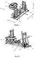
- FIGS. 1 and 2 represent a first embodiment of a power battery mounting and dismounting device on an electric or hybrid traction motor vehicle.
- FIG 3 illustrates a second embodiment, simplified with respect to the first as will be understood later.
- the elements in common in both embodiments are affected in the figures identical references.
- Each of these devices is designed to mount and dismount a battery 10 in a housing cell from below the vehicle.
- the battery mounting / dismounting device 10 comprises for this purpose a lifting table 11 intended indirectly to lock and unlock a battery 10 relative to the vehicle housing cell and to move the battery at least vertically when it is at the same time. unlocked state, in a vertical direction marked Z.
- a lifting table 11 intended indirectly to lock and unlock a battery 10 relative to the vehicle housing cell and to move the battery at least vertically when it is at the same time. unlocked state, in a vertical direction marked Z.
- the lifting table 11 thus carries an interaction member capable of interacting with the underside of the vehicle.
- the interaction member may comprise a relative positioning element of the lifting table 11 with respect to the vehicle and / or of attitude correction of the vehicle.
- This positioning element may be intended to compensate for horizontal offsets between the table 11 and the vehicle and possibly to generate a lifting of the vehicle, by raising the table 11, to a predetermined height to overcome differences in height between the different types of existing vehicles.
- the attitude correction element may consist of a rack with several points of contact with the vehicle, the bringing into contact of all the points of the rack with the vehicle can be achieved by a lifting of the vehicle, simultaneous or posterior to the vehicle. that corresponding to the relative positioning of the vehicle / table.
- These positioning and / or attitude correction elements can be associated with the table by a removable assembly, allowing disassembly of the latter relative to the lift table according to the case.
- the interaction member may comprise a support element of the battery 10 during its storage and / or its electric recharge, thus ensuring a battery support when it is disembarked from the table 11 of the device mounting and dismounting.
- a support element such as a pallet or can for example be called “lugette”, may especially be intended to facilitate the handling and storage of the battery outside the mounting / dismounting device.
- the mobility of the lifting table 11 in the vertical direction Z in addition to making it possible to fulfill its function of elevating the batteries, also allows the previously described interaction element to interact with the underside of the vehicle, for example. example possibly in the form of an approach and / or a veneering of the interaction member against the vehicle, so that the elements that constitute it (positioning element and / or correction plate and / or element battery support during storage and / or charging) can perform their functions.
- the mounting and dismounting device comprises a carriage 12 on which the lifting table 11 is mounted and configured to move the assembly constituted by the lifting table 11 and the interaction member in at least one direction of substantially horizontal movement. .
- this assembly it can be provided a possibility of horizontal translation of the carriage 12 in a first direction of movement X and possibly a possibility of horizontal translation of the lifting table 11 relative to the carriage 12 in a second direction of displacement Y. Otherwise said, the carriage 12 is in the latter eventuality configured so as to move the table Elevator 11 relative to itself in the second direction Y.
- the carriage 12 is designed to move in both directions X and Y, which are for example perpendicular to each other.
- the first and second embodiments thus provide for a displacement of the carriage 12 in the first direction X, while only the first embodiment provides for a horizontal displacement of the table 11 in the second direction Y for example with the aid of a moving the table relative to the carriage 12 on which it is mounted.
- the lifting table 11 can therefore advantageously change position from the mounting / dismounting of batteries on vehicles, for example to be able to participate in other operations necessary for the management of battery exchange, and this at different working heights, such as battery cleaning operations and / or battery installation and removal operations in storage cells and / or electric charging.
- the interaction member carried by the lifting table 11 may optionally comprise an actuating element 18 of a locking mechanism of a battery on the vehicle.
- a locking mechanism is thus able to vary between a locked state spatially immobilizing inside the vehicle housing cell the battery with which it cooperates in a mounted position and an unlocked state spatially releasing the battery from its mounted position.
- the actuating element can be designed so that an appropriate maneuver of the latter can control the passage of the locking mechanism from one state to another, this maneuver is done from below the vehicle for example.
- the locking mechanism that equips a vehicle can be configured so that its maneuver requires a constraint of the mechanism to obtain its disengagement and then a rotation (for example 90 degrees) of at least one latch (for example four in number) to obtain the locking and / or unlocking mechanism.
- the actuating element 18 is flexible in that it can be adjusted or changed to accommodate the different types of locking mechanisms that can be understood by different types of vehicles.
- this element 18 may advantageously comprise a standard interface and a number of standard and modular components to obtain an element 18 adapted for intervention on all types of battery and all motor vehicles.
- Such an actuating element 18 is also called by its English name "toolbox", as for example that described in the application published under the number FR2952334 .
- the horizontal movement of the table 11 by action of the carriage 12 thus advantageously makes it possible to possibly change the position of the actuating element 18 from the mounting / dismounting zone of the batteries on vehicles, in order, for example, to be able to use this element 18 in substitution. of the support element described above, or even come and use this element 18 to install and / or remove a battery in a storage cell of a storage structure and / or recharge in the case where the cell itself is advantageously equipped with a locking mechanism in the image of the vehicle housing cell.
- a possible but in no way limiting design consists in providing that the carriage 12 can comprise a rolling element 13 intended to ensure an overall translation of the carriage 12 (and therefore of the lifting table assembly 11 / interaction member) in at least the direction of movement X, or in addition in the direction of displacement Y, this which is not the case, however, Figures 1 and 2 .
- the displacement of the rolling element 13 can be obtained using onboard propulsion means or with the aid of external traction means (for example using cables, rack system).
- the carriage 12 may further comprise a lifting platform 14 vertically Z-shaped, connected to the rolling member 13 by any relative lifting means between these two parts.
- the vertical Z-shaped movement of the platform 14 relative to the rolling element 13 can be obtained by a pair of X-shifted forks 15, each of these forks being actuated in vertical displacement by at least one cable 16 whose scrolling is controlled for example by a corresponding motor 17 on board the rolling element 13.
- the relative elasticity of lifting cables 16 and 16' makes it possible to conform, that is to say to make parallel, the two planes that are the substantially horizontal plane of the vehicle (this plane having been established after attitude correction of the vehicle as described above) and the substantially horizontal plane of the battery (this plane having been established after positioning the battery on the table Elevator 11 as previously described).
- the cables 16 and 16 ' spaced from each other for example by being arranged symmetrically on either side of the lifting table 11, for example according to X, are both driven by the same motor 17, by the intermediate of a pulley axis 27 for the cable 16 'and via two pulleys axes 28 and 29 for the cable 16.
- the absence of parallelism between the two substantially horizontal planes is characterized by a slight angular deviation ⁇ X around the axis of rotation X and by a slight angular deviation ⁇ Y around the axis of rotation Y.
- the elasticity of the lifting cables 16 and 16 ' makes it possible to continue to raise slightly one side of the platform 14, for example the side raised by the cable 16' on the example of the figure 5 , while the other side of said platform 14 is already blocked by the underside of the vehicle, for example the side raised by the cable 16 on the example of the figure 5 .
- it is the latch parts arranged on the side of the battery 10 'which come into mechanical contact with their complementary part arranged on the side of the vehicle.
- the elasticity of the lifting cables 16 and 16 ' makes it possible to continue to slightly raise the platform 14 to one side or the other within the limit of the deformability of these cables and that any cable, even made of steel, is slightly elastic.
- the platform 14 inclines when the side raised by the cable 16 'continues to rise while the other side is blocked: the platform pivots around the X and Y axes so as to compensate for the deviations ⁇ X and ⁇ Y, the figure 5 illustrating the compensation of the difference ⁇ Y. It should also be noted that, although it is essentially the substantially horizontal plane of the battery that tilts, the substantially horizontal plane of the vehicle also tilts but to a much lesser extent.
- a connecting means which may optionally include relative vertical displacement means between the lifting table 11 and the lifting platform 14 and / or a horizontal moving means relative between the lifting table 11 and the platform 14 in the direction Y, which is the case only in the first embodiment. This latter possibility is particularly advantageously provided in the case where the rolling element 13 is not mounted movable in the Y direction.
- the relative vertical displacement means table 11 / platform 14 has the advantage to provide a global vertical displacement of the table 11 relative to the rolling element 13 which is telescopic, ie with a first vertical component (see arrow F1 on the figure 3 ) possibly consisting of a relative displacement table 11 / platform 14 and a second vertical component (see arrow F2 on the figure 3 )
- a first vertical component possibly consisting of a relative displacement table 11 / platform 14 and a second vertical component (see arrow F2 on the figure 3 )
- This is particularly advantageous in the case where the carriage 12 is arranged in a pit formed in the ground, to reduce as much as possible the height of the pit.
- the horizontal movement of the table 11 in Y is useful for example in the case where the table 11 participates in the installation and removal of batteries in the storage structure and / or electric recharge, to implement this structure is offset from the trajectory of the carriage 12 in the X direction.
- the possibility of horizontal displacement in Y of the table 11 with respect to the platform 14 can be replaced by or combined with a possibility of relative displacement by Y of the platform 14 with respect to the rolling element 13.
- the embodiment of the figure 3 is a simplification of that of Figures 1 and 2 in that in relation to the latter, the carriage 12 of the figure 3 is not intended to ensure a horizontal displacement of the table 11 in the Y direction, but only in the X direction.
- no Y displacement of the rolling element 13 and / or Y displacement is provided. of the platform 14 relative to the rolling element 13 and / or Y displacement of the table 11 relative to the platform 14.
- each of the mounting / dismounting devices of the two embodiments may comprise at least two tables. independent elevators 11, arranged in a manner offset in the Y direction.
- the carriage 12 is configured to rotate the single lifting table 11 about a vertical pivot axis.
- a mounting and dismounting device as mentioned above can thus be used for the arrangement of an electric or hybrid motor vehicle battery exchange station.
- the implementation of an example of such a station is schematically represented in a view from above on the figure 4 .
- the station may further include a path 21 along which the vehicles 19 are intended to circulate.
- the assembly and disassembly device can be implanted so as to have an orientation such that the carriage 12 moves in a direction of displacement X substantially perpendicular to the traffic trajectory of the vehicles 19 along the track 21.
- the direction of displacement X of the carriage 12 can indifferently be oriented parallel to the track 19.
- This station can be configured so that the movement of the assembly (table 11 and interaction member) is practiced from or to a transfer zone 22 in which a disassembled battery is transferred from the mounting and dismounting device to a device separate handling of the mounting / dismounting device or vice versa.
- This handling device which can take any design adapted to its function, is able to move the battery between the transfer zone 22 and a storage area and / or battery charge 23.
- a battery exchange method that the mounting and dismounting device allows to achieve is such that it comprises a step of moving the assembly constituted by the lift table and the interaction member with the vehicle, in at least one direction of substantially horizontal movement.
- the direction X of the assembly is perpendicular to the track 21, the direction X is substantially perpendicular to the longitudinal axis of the vehicle which undergoes the exchange of battery being parked in the mounting / dismounting zone 20.
- the direction of movement X of the assembly is substantially parallel to the longitudinal axis of the vehicle.
- the positioning and / or attitude correction element may include two positioners 25 offset laterally on either side of the housing unit, perpendicularly to the axis of the track 21, each of the positioners 25 being able to adopt example the shape of a rod whose free upper end is adapted to cooperate with complementary elements carried by the vehicle to compensate in a given range the horizontal offsets between the table 11 and the vehicle 19 may appear due to 'imprecise positioning of the vehicle.
- the trim elements may include for example two supports 26 front and rear offset longitudinally parallel to the axis of the track 21. On the figure 3 , alone the positioner 25 disposed to the left of the table 21 is visible, the positioner disposed to its right being hidden by the support 26 before.
- Each of the supports 26 may also adopt a rod shape whose upper free end is intended to support against the underside of the vehicle.
- the vehicle support function by the left positioner 25 is combined with the vehicle support by the supports 26 arranged on the right, so as to form a rack at least three feet whose vertical actuation by Z displacement of the table 11, provides a correction of attitude of the vehicle.
- These elements 25 and 26 can be mounted on the lift table removably as needed.
Landscapes
- Engineering & Computer Science (AREA)
- Mechanical Engineering (AREA)
- Transportation (AREA)
- Chemical & Material Sciences (AREA)
- Combustion & Propulsion (AREA)
- Power Engineering (AREA)
- Arrangement Or Mounting Of Propulsion Units For Vehicles (AREA)
- Battery Mounting, Suspending (AREA)
- Vehicle Cleaning, Maintenance, Repair, Refitting, And Outriggers (AREA)
- Electric Propulsion And Braking For Vehicles (AREA)
Claims (7)
- Vorrichtung zum Ein- und Ausbau einer Batterie (10') unter einem Elektro- oder Hybridfahrzeug (19), wobei die Unterseite des Fahrzeugs sich in einer ersten im Wesentlichen waagrechten Ebene befindet, wobei die Vorrichtung einen Hubtisch (11) aufweist, der ein Interaktionsorgan senkrecht verschiebt, das mit der Unterseite des Fahrzeugs interagieren kann, wobei das Interaktionsorgan vom Hubtisch mit der Unterseite des Fahrzeugs in mechanischen Kontakt gebracht wird, wobei die Vorrichtung dadurch gekennzeichnet ist, dass die Oberseite des Organs dann in einer zweiten im Wesentlichen waagrechten Ebene in einem Zustand angeordnet ist, der es dem Organ aufgrund einer relativen Neigung (ΔX, ΔY) zwischen der ersten und der zweiten Ebene nicht erlaubt, mit der Unterseite des Fahrzeugs zu interagieren, und der Hubtisch mittels mindestens zwei Kabeln (16, 16') angehoben wird, deren Elastizität es erlaubt, die relative Neigung der zwei Ebenen zu kompensieren, um es dem Organ zu erlauben, mit der Unterseite des Fahrzeugs zu interagieren.
- Vorrichtung nach Anspruch 1, dadurch gekennzeichnet, dass die Elastizität der Kabel (16, 16') es ermöglicht, die relative Neigung der zwei Ebenen in den Grenzen der Verformbarkeit der Kabel zu kompensieren.
- Vorrichtung nach Anspruch 1, dadurch gekennzeichnet, dass die Kabel (16, 16') symmetrisch zu beiden Seiten des Hubtischs (11) angeordnet sind.
- Vorrichtung nach Anspruch 1, dadurch gekennzeichnet, dass die Kabel (16, 16') von dem gleichen Motor (17) angetrieben werden.
- Vorrichtung nach Anspruch 1, dadurch gekennzeichnet, dass die Kabel (16, 16') mittels Riemenscheiben angetrieben werden.
- Vorrichtung nach Anspruch 1, dadurch gekennzeichnet, dass die Vorrichtung außerdem ein Trimmlagenkorrekturelement (25, 26) aufweist, das es ermöglicht, das Fahrzeug in die erste im Wesentlichen waagrechte Ebene zu bringen.
- Vorrichtung nach Anspruch 1, dadurch gekennzeichnet, dass, da das Interaktionsorgan ein Betätigungselement (18) eines Verriegelungs- und/oder Entriegelungsmechanismus der Batterie unter dem Fahrzeug aufweist, wobei der Mechanismus eine Vielzahl von Riegeln aufweist, die Elastizität der Kabel (16, 16') es ermöglicht, die relative Neigung der zwei Ebenen zu kompensieren, um die Betätigung der Riegel zu erlauben.
Applications Claiming Priority (2)
| Application Number | Priority Date | Filing Date | Title |
|---|---|---|---|
| FR1250219A FR2985484B1 (fr) | 2012-01-09 | 2012-01-09 | Dispositif de montage et de demontage de batterie de vehicule avec cables elastiques pour compenser les ecarts d'assiette de vehicule |
| PCT/FR2012/053046 WO2013104844A1 (fr) | 2012-01-09 | 2012-12-21 | Dispositif de montage et de démontage d'une batterie de véhicule |
Publications (2)
| Publication Number | Publication Date |
|---|---|
| EP2802491A1 EP2802491A1 (de) | 2014-11-19 |
| EP2802491B1 true EP2802491B1 (de) | 2016-05-25 |
Family
ID=46785510
Family Applications (1)
| Application Number | Title | Priority Date | Filing Date |
|---|---|---|---|
| EP12816768.1A Not-in-force EP2802491B1 (de) | 2012-01-09 | 2012-12-21 | Vorrichtung zum installieren und deinstallieren einer fahrzeugbatterie |
Country Status (6)
| Country | Link |
|---|---|
| US (1) | US20140360011A1 (de) |
| EP (1) | EP2802491B1 (de) |
| KR (1) | KR101977774B1 (de) |
| CN (1) | CN104136287B (de) |
| FR (1) | FR2985484B1 (de) |
| WO (1) | WO2013104844A1 (de) |
Families Citing this family (19)
| Publication number | Priority date | Publication date | Assignee | Title |
|---|---|---|---|---|
| SE1350769A1 (sv) * | 2013-06-25 | 2014-08-26 | Sten Corfitsen | Förfarande och anordning för byte av ett batteri i ett fordon |
| CN107380137B (zh) * | 2017-07-31 | 2023-04-18 | 杭州世楷自动化设备有限公司 | 一种电动汽车换电池用的定位平台 |
| CN109501756A (zh) * | 2017-09-12 | 2019-03-22 | 上海蔚来汽车有限公司 | 电动汽车的自动换电系统 |
| USD900183S1 (en) * | 2017-11-08 | 2020-10-27 | Nio Nextev Limited | Battery swapping vehicle |
| TWD196783S (zh) * | 2017-11-08 | 2019-04-01 | 香港商蔚來汽車有限公司 | 換電平台 |
| TWD198584S (zh) * | 2017-11-08 | 2019-07-11 | 香港商蔚來汽車有限公司 | 換電平台之側部設備 |
| CN109501753B (zh) * | 2017-11-22 | 2021-11-23 | 蔚来控股有限公司 | 电动汽车的自动换电平台和换电站 |
| CN113212231B (zh) * | 2017-11-30 | 2023-10-03 | 上海电巴新能源科技有限公司 | 换电站的换电方法 |
| IT201900005092A1 (it) * | 2019-04-04 | 2020-10-04 | Texa Spa | Ponte sollevatore per veicoli |
| CN110255031B (zh) * | 2019-06-27 | 2024-06-11 | 佛山市丁丁自动化科技有限公司 | Agv电池自动充换设备及其更换方法 |
| CN111959342A (zh) * | 2020-08-31 | 2020-11-20 | 博众精工科技股份有限公司 | 车辆纠偏方法及系统及换电站 |
| EP3981629B1 (de) | 2020-10-06 | 2025-01-29 | Volvo Truck Corporation | Verfahren zum bewegen eines schweren gegenstandes |
| CN115411337B (zh) * | 2021-05-27 | 2024-10-01 | 华晨宝马汽车有限公司 | 用于车辆生产线的电池装配辅助设备和方法 |
| CN113291197B (zh) * | 2021-05-28 | 2023-10-24 | 蓝谷智慧(北京)能源科技有限公司 | 换电站及其换电控制方法、介质、设备与充电控制装置 |
| CN113291198A (zh) * | 2021-05-28 | 2021-08-24 | 蓝谷智慧(北京)能源科技有限公司 | 电池包出库控制方法以及换电站的控制系统 |
| JP7513131B1 (ja) * | 2023-02-01 | 2024-07-09 | いすゞ自動車株式会社 | バッテリの着脱構造 |
| US20240383368A1 (en) * | 2023-05-16 | 2024-11-21 | Ample, Inc. | Battery-Exchange System and Service Station |
| CN116552461B (zh) * | 2023-07-10 | 2023-11-10 | 宁德时代新能源科技股份有限公司 | 换电站和换电方法 |
| CN222179462U (zh) * | 2024-03-15 | 2024-12-17 | 蔚来汽车科技(安徽)有限公司 | 换电机器人及充换电站 |
Family Cites Families (46)
| Publication number | Priority date | Publication date | Assignee | Title |
|---|---|---|---|---|
| US2480609A (en) * | 1945-11-16 | 1949-08-30 | Donald H Hobbie | Portable silage rack |
| US2809759A (en) * | 1956-05-08 | 1957-10-15 | Alford D Manker | Fork lift tow bracket |
| US2894605A (en) * | 1956-10-02 | 1959-07-14 | Lester W Leavitt | Portable fork lift truck |
| AT348875B (de) * | 1975-12-24 | 1979-03-12 | Voith Gmbh J M | Einrichtung zum horizontalen positionieren von batteriebetriebenen fahrzeugen an batteriewechselstationen |
| DE2758534A1 (de) * | 1977-12-28 | 1979-07-05 | Deutsche Automobilgesellsch | Einrichtung zur aufnahme eines auswechselbaren energiespeichers in einem kraftfahrzeug |
| US4334819A (en) * | 1980-03-27 | 1982-06-15 | Hammerslag Julius G | Battery charging system |
| US4450400A (en) * | 1981-12-04 | 1984-05-22 | Gwyn Marion V | Battery replacement system for electric vehicles |
| US4488326A (en) * | 1982-09-30 | 1984-12-18 | Autoquip Corporation | Pallet dock lift |
| GB8408346D0 (en) * | 1984-03-30 | 1984-05-10 | Airlec Vehicles Ltd | Mobile lift loaders |
| US4712653A (en) * | 1985-08-14 | 1987-12-15 | Lift-R Technologies, Inc. | Energy-recycling scissors lift |
| US4690250A (en) * | 1985-09-05 | 1987-09-01 | Car-O-Liner Company | Vehicle bench lift |
| US5011358A (en) * | 1988-10-25 | 1991-04-30 | Andersen Eric T | Height indicator for a fork lift truck |
| US5023790A (en) * | 1989-02-17 | 1991-06-11 | Whs Robotics | Automatic guided vehicle system |
| KR970003868B1 (ko) * | 1991-10-14 | 1997-03-22 | 가부시끼가이샤 다이후꾸 | 입체주차설비 |
| US5193649A (en) * | 1992-06-23 | 1993-03-16 | Steven Lee | Platform car |
| JP3530870B2 (ja) * | 1993-03-15 | 2004-05-24 | 四国電力株式会社 | 電気自動車のバッテリ交換装置 |
| US5301765A (en) * | 1993-05-14 | 1994-04-12 | Swanson Lennart H | Battery pack installation and storage system for electric vehicles |
| DE9414820U1 (de) * | 1994-09-13 | 1995-01-12 | Eissfeller, Roman, 78194 Immendingen | Industrieroboter |
| US5612606A (en) * | 1994-09-15 | 1997-03-18 | David C. Guimarin | Battery exchange system for electric vehicles |
| US5642979A (en) * | 1995-01-09 | 1997-07-01 | N.R.S. Systems, Inc. | Roll handling apparatus for fork lift trucks |
| US6112858A (en) * | 1998-07-21 | 2000-09-05 | Harley-Davidson Motor Company | Assembly line fixture |
| US20030209375A1 (en) * | 1999-01-25 | 2003-11-13 | Zip Charge Corporation | Electrical vehicle energy supply system, electrical vehicle battery, electrical vehicle battery charging apparatus, battery supply apparatus, and electrical vehicle battery management system |
| CA2446230A1 (en) * | 2001-06-20 | 2003-01-03 | Meridian Automotive Systems, Inc. | Combination pickup truck liftgate/tailgate |
| WO2003013989A1 (en) * | 2001-08-08 | 2003-02-20 | Jervis B. Webb Company | Belt conveyor system with carrier plate |
| US6857493B2 (en) * | 2002-02-13 | 2005-02-22 | Paragon Technologies, Inc. | Automatic load positioning for a conveyor cart |
| US7070167B1 (en) * | 2003-01-14 | 2006-07-04 | Herkules Equipment Corporation | Low profile lift apparatus with one to one direct lifting ratio |
| GB0323436D0 (en) * | 2003-10-07 | 2003-11-05 | Mccann Martin | Battery arrangement |
| DE102007032210B4 (de) * | 2007-04-19 | 2010-04-08 | Höltzel, Thomas | Verfahren und Vorrichtung zum Austausch von Akkumulatoren für Elektrofahrzeuge |
| US20080294283A1 (en) * | 2007-05-25 | 2008-11-27 | Ronald Ligrano | Battery exchange station and a method of changing therein |
| US8052120B2 (en) * | 2008-05-08 | 2011-11-08 | Herkules Equipment Corporation | Multipurpose modular lift platform |
| TWI408535B (zh) * | 2008-06-27 | 2013-09-11 | Wistron Corp | 電子設備 |
| US7993155B2 (en) * | 2008-09-19 | 2011-08-09 | Better Place GmbH | System for electrically connecting batteries to electric vehicles |
| US8172255B1 (en) * | 2008-11-07 | 2012-05-08 | Rebecca Martin | Height-adjustable kitchen cart |
| US20110251935A1 (en) * | 2008-12-15 | 2011-10-13 | Guy German | Mobile Battery Replacement Unit |
| FR2947504B1 (fr) * | 2009-07-03 | 2014-11-28 | Renault Sas | Procede et systeme de remplacement d'un conteneur d'energie d'alimentation d'un moteur d'entrainement d'un vehicule automobile |
| JP5263075B2 (ja) * | 2009-08-24 | 2013-08-14 | 株式会社豊田自動織機 | 電気自動車のバッテリ交換位置決め装置 |
| FR2950014B1 (fr) * | 2009-09-14 | 2012-02-10 | Renault Sa | Structure de support pour batterie de traction de vehicule electrique. |
| FR2952334B1 (fr) | 2009-11-12 | 2011-10-28 | Renault Sa | Dispositif pour le remplacement d'une batterie d'alimentation d'un moteur d'entrainement d'un vehicule automobile. |
| DE102009053050A1 (de) * | 2009-11-16 | 2011-05-19 | Siemens Aktiengesellschaft | Verfahren und Vorrichtung zum Austauschen einer Batterie in einem Fahrzeug |
| FR2954592B1 (fr) * | 2009-12-21 | 2012-01-06 | Renault Sa | Procede et syteme de montage ou demontage d'une batterie d'un vehicule automobile. |
| DE102011100781A1 (de) * | 2010-05-07 | 2011-12-15 | Manuel Czech | Akkumulatorwechelsystem zum Austausch von Akkumulatoren für Elektrofahrzeuge |
| CN101870284B (zh) * | 2010-06-18 | 2012-11-28 | 崔丽娜 | 电动汽车的电池自动更换系统以及自动更换电动汽车电池的方法 |
| CN102303589B (zh) * | 2011-08-31 | 2012-11-28 | 昆明船舶设备集团有限公司 | 底部取电可自锁及快换电池的电动客车电池箱系统 |
| JP5798878B2 (ja) * | 2011-10-13 | 2015-10-21 | カヤバ工業株式会社 | 搬送台車 |
| WO2014166511A1 (de) * | 2013-04-10 | 2014-10-16 | Christoph Mohr | Hubtisch und förderanlage |
| US9371083B1 (en) * | 2014-12-16 | 2016-06-21 | Acu-Pac, Inc. | Collapsible stackable storage cart |
-
2012
- 2012-01-09 FR FR1250219A patent/FR2985484B1/fr not_active Expired - Fee Related
- 2012-12-21 CN CN201280070910.6A patent/CN104136287B/zh not_active Expired - Fee Related
- 2012-12-21 EP EP12816768.1A patent/EP2802491B1/de not_active Not-in-force
- 2012-12-21 US US14/371,205 patent/US20140360011A1/en not_active Abandoned
- 2012-12-21 KR KR1020147022160A patent/KR101977774B1/ko active Active
- 2012-12-21 WO PCT/FR2012/053046 patent/WO2013104844A1/fr not_active Ceased
Also Published As
| Publication number | Publication date |
|---|---|
| CN104136287A (zh) | 2014-11-05 |
| KR20140119728A (ko) | 2014-10-10 |
| KR101977774B1 (ko) | 2019-05-13 |
| US20140360011A1 (en) | 2014-12-11 |
| WO2013104844A1 (fr) | 2013-07-18 |
| FR2985484A1 (fr) | 2013-07-12 |
| FR2985484B1 (fr) | 2014-02-07 |
| EP2802491A1 (de) | 2014-11-19 |
| CN104136287B (zh) | 2016-08-24 |
Similar Documents
| Publication | Publication Date | Title |
|---|---|---|
| EP2802491B1 (de) | Vorrichtung zum installieren und deinstallieren einer fahrzeugbatterie | |
| EP2534020B1 (de) | Vorrichtung für das ersetzen einer versorgungsbatterie eines antriebsmotors eines kraftfahrzeugs | |
| EP2825404B1 (de) | Verriegelungs- und entriegelungssystem eines gegenstands an einer struktur, mit in die werkzeuge integrierten anschlag- und ausrichtelementen | |
| EP2499013B1 (de) | Vorrichtung zum auswechseln einer batterie zum versorgen einer antriebsmotors eines kraftfahrzeuges | |
| EP2726345B1 (de) | Positionierung eines kraftfahrzeugs und austausch einer stromversorgungsbatterie bei einem fahrzeug | |
| EP2516220B1 (de) | Verfahren und system zur montage oder entfernung einer kraftfahrzeugbatterie | |
| EP2739511A1 (de) | Anordnung zur aufbewahrung von kraftfahrzeugbatterien mit mechanismus zum blockieren der batterien in den aufbewahrungszellen | |
| EP2825405B1 (de) | System zur versperrung/entsperrung eines objekts unter einer struktur mit einem haken zum ziehen und tragen davon | |
| EP2776291A1 (de) | Halbautomatische station zum wechseln einer traktionsbatterie eines elektro-oder hybridfahrzeugs | |
| EP3898325A1 (de) | Förderer zum bewegen von vierrädrigen fahrzeugen | |
| EP2776292A1 (de) | Halbautomatische station zum austauschen der traktionsbatterie eines elektro-oder hybridfahrzeugs | |
| FR2933656A1 (fr) | Dispositif de verrouillage et deverouillage automatiques d'un bac batterie de vehicule automobile electrique, vehicule et station d'echange de batteries equipes d'un tel dispositif | |
| FR3058987B1 (fr) | Organe et chariot pour la depose, le transport, et la maintenance, d'une turbomachine | |
| WO2011001066A1 (fr) | Procédé et système de remplacement d'un conteneur d'énergie d'alimentation d'un moteur d'entraînement d'un véhicule automobile | |
| WO2012032242A1 (fr) | Procede et systeme de remplacement d'un conteneur d'energie d'alimentation d'un moteur d'entrainement d'un vehicule automobile | |
| EP2517283A1 (de) | Werkzeug zur montage/entfernung einer kraftfahrzeugbatterie | |
| WO2020193540A1 (fr) | Station de recharge pour drone | |
| EP4628430A1 (de) | Anordnung für ein automatisiertes lager- und abrufsystem | |
| FR2919239A1 (fr) | Vehicule de transfert de conteneurs a bagages. | |
| FR1465671A (fr) | élévateur pour véhicules | |
| WO2024126557A1 (fr) | Nacelle élévatrice à motorisation électrique | |
| EP4703265A1 (de) | System zum empfang elektrischer energie für die bewegung eines flugzeugs in der rollphase |
Legal Events
| Date | Code | Title | Description |
|---|---|---|---|
| PUAI | Public reference made under article 153(3) epc to a published international application that has entered the european phase |
Free format text: ORIGINAL CODE: 0009012 |
|
| 17P | Request for examination filed |
Effective date: 20140703 |
|
| AK | Designated contracting states |
Kind code of ref document: A1 Designated state(s): AL AT BE BG CH CY CZ DE DK EE ES FI FR GB GR HR HU IE IS IT LI LT LU LV MC MK MT NL NO PL PT RO RS SE SI SK SM TR |
|
| DAX | Request for extension of the european patent (deleted) | ||
| GRAP | Despatch of communication of intention to grant a patent |
Free format text: ORIGINAL CODE: EPIDOSNIGR1 |
|
| INTG | Intention to grant announced |
Effective date: 20151210 |
|
| INTG | Intention to grant announced |
Effective date: 20151214 |
|
| GRAS | Grant fee paid |
Free format text: ORIGINAL CODE: EPIDOSNIGR3 |
|
| GRAA | (expected) grant |
Free format text: ORIGINAL CODE: 0009210 |
|
| AK | Designated contracting states |
Kind code of ref document: B1 Designated state(s): AL AT BE BG CH CY CZ DE DK EE ES FI FR GB GR HR HU IE IS IT LI LT LU LV MC MK MT NL NO PL PT RO RS SE SI SK SM TR |
|
| REG | Reference to a national code |
Ref country code: GB Ref legal event code: FG4D Free format text: NOT ENGLISH |
|
| REG | Reference to a national code |
Ref country code: CH Ref legal event code: EP |
|
| REG | Reference to a national code |
Ref country code: IE Ref legal event code: FG4D Free format text: LANGUAGE OF EP DOCUMENT: FRENCH Ref country code: AT Ref legal event code: REF Ref document number: 802018 Country of ref document: AT Kind code of ref document: T Effective date: 20160615 |
|
| REG | Reference to a national code |
Ref country code: DE Ref legal event code: R096 Ref document number: 602012019045 Country of ref document: DE |
|
| REG | Reference to a national code |
Ref country code: LT Ref legal event code: MG4D |
|
| REG | Reference to a national code |
Ref country code: NL Ref legal event code: MP Effective date: 20160525 |
|
| PG25 | Lapsed in a contracting state [announced via postgrant information from national office to epo] |
Ref country code: NL Free format text: LAPSE BECAUSE OF FAILURE TO SUBMIT A TRANSLATION OF THE DESCRIPTION OR TO PAY THE FEE WITHIN THE PRESCRIBED TIME-LIMIT Effective date: 20160525 Ref country code: FI Free format text: LAPSE BECAUSE OF FAILURE TO SUBMIT A TRANSLATION OF THE DESCRIPTION OR TO PAY THE FEE WITHIN THE PRESCRIBED TIME-LIMIT Effective date: 20160525 Ref country code: LT Free format text: LAPSE BECAUSE OF FAILURE TO SUBMIT A TRANSLATION OF THE DESCRIPTION OR TO PAY THE FEE WITHIN THE PRESCRIBED TIME-LIMIT Effective date: 20160525 Ref country code: NO Free format text: LAPSE BECAUSE OF FAILURE TO SUBMIT A TRANSLATION OF THE DESCRIPTION OR TO PAY THE FEE WITHIN THE PRESCRIBED TIME-LIMIT Effective date: 20160825 |
|
| REG | Reference to a national code |
Ref country code: AT Ref legal event code: MK05 Ref document number: 802018 Country of ref document: AT Kind code of ref document: T Effective date: 20160525 |
|
| PG25 | Lapsed in a contracting state [announced via postgrant information from national office to epo] |
Ref country code: GR Free format text: LAPSE BECAUSE OF FAILURE TO SUBMIT A TRANSLATION OF THE DESCRIPTION OR TO PAY THE FEE WITHIN THE PRESCRIBED TIME-LIMIT Effective date: 20160826 Ref country code: ES Free format text: LAPSE BECAUSE OF FAILURE TO SUBMIT A TRANSLATION OF THE DESCRIPTION OR TO PAY THE FEE WITHIN THE PRESCRIBED TIME-LIMIT Effective date: 20160525 Ref country code: SE Free format text: LAPSE BECAUSE OF FAILURE TO SUBMIT A TRANSLATION OF THE DESCRIPTION OR TO PAY THE FEE WITHIN THE PRESCRIBED TIME-LIMIT Effective date: 20160525 Ref country code: PT Free format text: LAPSE BECAUSE OF FAILURE TO SUBMIT A TRANSLATION OF THE DESCRIPTION OR TO PAY THE FEE WITHIN THE PRESCRIBED TIME-LIMIT Effective date: 20160926 Ref country code: RS Free format text: LAPSE BECAUSE OF FAILURE TO SUBMIT A TRANSLATION OF THE DESCRIPTION OR TO PAY THE FEE WITHIN THE PRESCRIBED TIME-LIMIT Effective date: 20160525 Ref country code: LV Free format text: LAPSE BECAUSE OF FAILURE TO SUBMIT A TRANSLATION OF THE DESCRIPTION OR TO PAY THE FEE WITHIN THE PRESCRIBED TIME-LIMIT Effective date: 20160525 |
|
| REG | Reference to a national code |
Ref country code: FR Ref legal event code: PLFP Year of fee payment: 5 |
|
| PG25 | Lapsed in a contracting state [announced via postgrant information from national office to epo] |
Ref country code: IT Free format text: LAPSE BECAUSE OF FAILURE TO SUBMIT A TRANSLATION OF THE DESCRIPTION OR TO PAY THE FEE WITHIN THE PRESCRIBED TIME-LIMIT Effective date: 20160525 |
|
| PG25 | Lapsed in a contracting state [announced via postgrant information from national office to epo] |
Ref country code: RO Free format text: LAPSE BECAUSE OF FAILURE TO SUBMIT A TRANSLATION OF THE DESCRIPTION OR TO PAY THE FEE WITHIN THE PRESCRIBED TIME-LIMIT Effective date: 20160525 Ref country code: SK Free format text: LAPSE BECAUSE OF FAILURE TO SUBMIT A TRANSLATION OF THE DESCRIPTION OR TO PAY THE FEE WITHIN THE PRESCRIBED TIME-LIMIT Effective date: 20160525 Ref country code: CZ Free format text: LAPSE BECAUSE OF FAILURE TO SUBMIT A TRANSLATION OF THE DESCRIPTION OR TO PAY THE FEE WITHIN THE PRESCRIBED TIME-LIMIT Effective date: 20160525 Ref country code: DK Free format text: LAPSE BECAUSE OF FAILURE TO SUBMIT A TRANSLATION OF THE DESCRIPTION OR TO PAY THE FEE WITHIN THE PRESCRIBED TIME-LIMIT Effective date: 20160525 Ref country code: EE Free format text: LAPSE BECAUSE OF FAILURE TO SUBMIT A TRANSLATION OF THE DESCRIPTION OR TO PAY THE FEE WITHIN THE PRESCRIBED TIME-LIMIT Effective date: 20160525 |
|
| PG25 | Lapsed in a contracting state [announced via postgrant information from national office to epo] |
Ref country code: AT Free format text: LAPSE BECAUSE OF FAILURE TO SUBMIT A TRANSLATION OF THE DESCRIPTION OR TO PAY THE FEE WITHIN THE PRESCRIBED TIME-LIMIT Effective date: 20160525 Ref country code: PL Free format text: LAPSE BECAUSE OF FAILURE TO SUBMIT A TRANSLATION OF THE DESCRIPTION OR TO PAY THE FEE WITHIN THE PRESCRIBED TIME-LIMIT Effective date: 20160525 Ref country code: SM Free format text: LAPSE BECAUSE OF FAILURE TO SUBMIT A TRANSLATION OF THE DESCRIPTION OR TO PAY THE FEE WITHIN THE PRESCRIBED TIME-LIMIT Effective date: 20160525 |
|
| REG | Reference to a national code |
Ref country code: DE Ref legal event code: R097 Ref document number: 602012019045 Country of ref document: DE |
|
| PLBE | No opposition filed within time limit |
Free format text: ORIGINAL CODE: 0009261 |
|
| STAA | Information on the status of an ep patent application or granted ep patent |
Free format text: STATUS: NO OPPOSITION FILED WITHIN TIME LIMIT |
|
| 26N | No opposition filed |
Effective date: 20170228 |
|
| PG25 | Lapsed in a contracting state [announced via postgrant information from national office to epo] |
Ref country code: SI Free format text: LAPSE BECAUSE OF FAILURE TO SUBMIT A TRANSLATION OF THE DESCRIPTION OR TO PAY THE FEE WITHIN THE PRESCRIBED TIME-LIMIT Effective date: 20160525 Ref country code: BE Free format text: LAPSE BECAUSE OF NON-PAYMENT OF DUE FEES Effective date: 20161231 |
|
| REG | Reference to a national code |
Ref country code: CH Ref legal event code: PL |
|
| PG25 | Lapsed in a contracting state [announced via postgrant information from national office to epo] |
Ref country code: MC Free format text: LAPSE BECAUSE OF FAILURE TO SUBMIT A TRANSLATION OF THE DESCRIPTION OR TO PAY THE FEE WITHIN THE PRESCRIBED TIME-LIMIT Effective date: 20160525 |
|
| REG | Reference to a national code |
Ref country code: IE Ref legal event code: MM4A |
|
| PG25 | Lapsed in a contracting state [announced via postgrant information from national office to epo] |
Ref country code: LU Free format text: LAPSE BECAUSE OF NON-PAYMENT OF DUE FEES Effective date: 20161221 Ref country code: LI Free format text: LAPSE BECAUSE OF NON-PAYMENT OF DUE FEES Effective date: 20161231 Ref country code: CH Free format text: LAPSE BECAUSE OF NON-PAYMENT OF DUE FEES Effective date: 20161231 |
|
| PG25 | Lapsed in a contracting state [announced via postgrant information from national office to epo] |
Ref country code: IE Free format text: LAPSE BECAUSE OF NON-PAYMENT OF DUE FEES Effective date: 20161221 |
|
| REG | Reference to a national code |
Ref country code: FR Ref legal event code: PLFP Year of fee payment: 6 |
|
| PGFP | Annual fee paid to national office [announced via postgrant information from national office to epo] |
Ref country code: FR Payment date: 20171221 Year of fee payment: 6 Ref country code: DE Payment date: 20171211 Year of fee payment: 6 |
|
| REG | Reference to a national code |
Ref country code: BE Ref legal event code: MM Effective date: 20161231 |
|
| PGFP | Annual fee paid to national office [announced via postgrant information from national office to epo] |
Ref country code: GB Payment date: 20171221 Year of fee payment: 6 |
|
| PG25 | Lapsed in a contracting state [announced via postgrant information from national office to epo] |
Ref country code: HU Free format text: LAPSE BECAUSE OF FAILURE TO SUBMIT A TRANSLATION OF THE DESCRIPTION OR TO PAY THE FEE WITHIN THE PRESCRIBED TIME-LIMIT; INVALID AB INITIO Effective date: 20121221 |
|
| PG25 | Lapsed in a contracting state [announced via postgrant information from national office to epo] |
Ref country code: MK Free format text: LAPSE BECAUSE OF FAILURE TO SUBMIT A TRANSLATION OF THE DESCRIPTION OR TO PAY THE FEE WITHIN THE PRESCRIBED TIME-LIMIT Effective date: 20160525 Ref country code: HR Free format text: LAPSE BECAUSE OF FAILURE TO SUBMIT A TRANSLATION OF THE DESCRIPTION OR TO PAY THE FEE WITHIN THE PRESCRIBED TIME-LIMIT Effective date: 20160525 Ref country code: IS Free format text: LAPSE BECAUSE OF FAILURE TO SUBMIT A TRANSLATION OF THE DESCRIPTION OR TO PAY THE FEE WITHIN THE PRESCRIBED TIME-LIMIT Effective date: 20160525 Ref country code: CY Free format text: LAPSE BECAUSE OF FAILURE TO SUBMIT A TRANSLATION OF THE DESCRIPTION OR TO PAY THE FEE WITHIN THE PRESCRIBED TIME-LIMIT Effective date: 20160525 |
|
| PG25 | Lapsed in a contracting state [announced via postgrant information from national office to epo] |
Ref country code: BG Free format text: LAPSE BECAUSE OF FAILURE TO SUBMIT A TRANSLATION OF THE DESCRIPTION OR TO PAY THE FEE WITHIN THE PRESCRIBED TIME-LIMIT Effective date: 20160525 |
|
| PG25 | Lapsed in a contracting state [announced via postgrant information from national office to epo] |
Ref country code: MT Free format text: LAPSE BECAUSE OF FAILURE TO SUBMIT A TRANSLATION OF THE DESCRIPTION OR TO PAY THE FEE WITHIN THE PRESCRIBED TIME-LIMIT Effective date: 20160525 |
|
| PG25 | Lapsed in a contracting state [announced via postgrant information from national office to epo] |
Ref country code: TR Free format text: LAPSE BECAUSE OF FAILURE TO SUBMIT A TRANSLATION OF THE DESCRIPTION OR TO PAY THE FEE WITHIN THE PRESCRIBED TIME-LIMIT Effective date: 20160525 Ref country code: AL Free format text: LAPSE BECAUSE OF FAILURE TO SUBMIT A TRANSLATION OF THE DESCRIPTION OR TO PAY THE FEE WITHIN THE PRESCRIBED TIME-LIMIT Effective date: 20160525 |
|
| REG | Reference to a national code |
Ref country code: DE Ref legal event code: R119 Ref document number: 602012019045 Country of ref document: DE |
|
| GBPC | Gb: european patent ceased through non-payment of renewal fee |
Effective date: 20181221 |
|
| PG25 | Lapsed in a contracting state [announced via postgrant information from national office to epo] |
Ref country code: DE Free format text: LAPSE BECAUSE OF NON-PAYMENT OF DUE FEES Effective date: 20190702 Ref country code: FR Free format text: LAPSE BECAUSE OF NON-PAYMENT OF DUE FEES Effective date: 20181231 |
|
| PG25 | Lapsed in a contracting state [announced via postgrant information from national office to epo] |
Ref country code: GB Free format text: LAPSE BECAUSE OF NON-PAYMENT OF DUE FEES Effective date: 20181221 |