EP2802637B1 - Verfahren zur bereitstellung eines dampfförmigen gereinigten roh-c4-schnittes als einsatzstrom für eine extraktivdestillation mit einem selektiven lösungsmittel - Google Patents
Verfahren zur bereitstellung eines dampfförmigen gereinigten roh-c4-schnittes als einsatzstrom für eine extraktivdestillation mit einem selektiven lösungsmittel Download PDFInfo
- Publication number
- EP2802637B1 EP2802637B1 EP13700159.0A EP13700159A EP2802637B1 EP 2802637 B1 EP2802637 B1 EP 2802637B1 EP 13700159 A EP13700159 A EP 13700159A EP 2802637 B1 EP2802637 B1 EP 2802637B1
- Authority
- EP
- European Patent Office
- Prior art keywords
- cut
- crude
- hydrocarbons
- vaporous
- purified
- Prior art date
- Legal status (The legal status is an assumption and is not a legal conclusion. Google has not performed a legal analysis and makes no representation as to the accuracy of the status listed.)
- Active
Links
Images
Classifications
-
- C—CHEMISTRY; METALLURGY
- C10—PETROLEUM, GAS OR COKE INDUSTRIES; TECHNICAL GASES CONTAINING CARBON MONOXIDE; FUELS; LUBRICANTS; PEAT
- C10G—CRACKING HYDROCARBON OILS; PRODUCTION OF LIQUID HYDROCARBON MIXTURES, e.g. BY DESTRUCTIVE HYDROGENATION, OLIGOMERISATION, POLYMERISATION; RECOVERY OF HYDROCARBON OILS FROM OIL-SHALE, OIL-SAND, OR GASES; REFINING MIXTURES MAINLY CONSISTING OF HYDROCARBONS; REFORMING OF NAPHTHA; MINERAL WAXES
- C10G21/00—Refining of hydrocarbon oils, in the absence of hydrogen, by extraction with selective solvents
- C10G21/28—Recovery of used solvent
-
- C—CHEMISTRY; METALLURGY
- C10—PETROLEUM, GAS OR COKE INDUSTRIES; TECHNICAL GASES CONTAINING CARBON MONOXIDE; FUELS; LUBRICANTS; PEAT
- C10G—CRACKING HYDROCARBON OILS; PRODUCTION OF LIQUID HYDROCARBON MIXTURES, e.g. BY DESTRUCTIVE HYDROGENATION, OLIGOMERISATION, POLYMERISATION; RECOVERY OF HYDROCARBON OILS FROM OIL-SHALE, OIL-SAND, OR GASES; REFINING MIXTURES MAINLY CONSISTING OF HYDROCARBONS; REFORMING OF NAPHTHA; MINERAL WAXES
- C10G21/00—Refining of hydrocarbon oils, in the absence of hydrogen, by extraction with selective solvents
- C10G21/06—Refining of hydrocarbon oils, in the absence of hydrogen, by extraction with selective solvents characterised by the solvent used
- C10G21/12—Organic compounds only
-
- C—CHEMISTRY; METALLURGY
- C10—PETROLEUM, GAS OR COKE INDUSTRIES; TECHNICAL GASES CONTAINING CARBON MONOXIDE; FUELS; LUBRICANTS; PEAT
- C10L—FUELS NOT OTHERWISE PROVIDED FOR; NATURAL GAS; SYNTHETIC NATURAL GAS OBTAINED BY PROCESSES NOT COVERED BY SUBCLASSES C10G OR C10K; LIQUIFIED PETROLEUM GAS; USE OF ADDITIVES TO FUELS OR FIRES; FIRE-LIGHTERS
- C10L3/00—Gaseous fuels; Natural gas; Synthetic natural gas obtained by processes not covered by subclass C10G, C10K; Liquefied petroleum gas
- C10L3/12—Liquefied petroleum gas
Definitions
- the invention relates to a process for providing a gaseous purified crude C 4 cut as feed stream for extractive distillation with a selective solvent.
- C 4 cut denotes mixtures of hydrocarbons having predominantly 4 carbon atoms per molecule.
- C 4 cuts are obtained, for example, in the production of ethylene and / or propylene by thermal cracking, usually in steam crackers, especially naphtha crackers or fluidized catalytic cracking (FCC) crackers of a petroleum fraction, such as liquefied petroleum gas, light gasoline or gas oil.
- C 4 cuts are obtained in the catalytic dehydrogenation of n-butane and / or n-butene.
- C 4 cuts usually contain butanes, butenes, 1,3-butadiene, small amounts of C 3 and C 4 acetylenes, 1,2-butadiene and C 5+ hydrocarbons.
- the separation of C 4 cuts is a complicated distillation problem because of the small differences in the relative volatilities of the components. Therefore, the separation is carried out by a so-called extractive distillation, ie a distillation with the addition of a selective solvent (also referred to as extractant), which has a higher boiling point than the mixture to be separated and which increases the differences in the relative volatilities of the components to be separated.
- extractive distillation ie a distillation with the addition of a selective solvent (also referred to as extractant), which has a higher boiling point than the mixture to be separated and which increases the differences in the relative volatilities of the components to be separated.
- Crude C 4 cuts contain impurities which would lead to problems in the extractive distillation, in particular foaming of the solvent and apparatus fouling, so that they must be separated just before the feed of the crude C 4 cut for extractive distillation in order to obtain a reliable Ensure operation of the extractive distillation.
- Impurities leading to the above problems are especially higher than boiling components, especially C " 5+” hydrocarbons (predominantly hydrocarbons having 5 or more carbon atoms per molecule, isoprene, C " 4" oligomers and polymers, ie Oligomers and optionally polymers of butadiene of the formula (C 4 H 6 ) n , where n is greater than or equal to 2.
- C " 5+” hydrocarbons predominantly hydrocarbons having 5 or more carbon atoms per molecule, isoprene, C " 4" oligomers and polymers, ie Oligomers and optionally polymers of butadiene of the formula (C 4 H 6 ) n , where n is greater than or equal to 2.
- the proportion of C 5+ hydrocarbons in C 4 cuts is dependent in particular on the operating conditions during thermal cracking and is up to to 1000 ppm by weight or even up to 5000 ppm by weight, in individual cases up to 1% by weight, based on the total weight of the crude C 4 cut
- the C 4 -oligomers and polymers are formed in particular by Storage and transport, their proportion is therefore largely dependent on the storage and transport conditions, in particular temperature, duration, inerting of the atmosphere under which the storage and / or transport takes place.
- C 3 hydrocarbons ie hydrocarbons having three carbon atoms per molecule
- the extractive distillation can cause problems; this is in particular methylacetylene, which has a similar affinity to the commonly used selective solvents such as 1,3-butadiene.
- the proportion of C 3 hydrocarbons should therefore be limited in the feed stream for extractive distillation to a maximum of 50 ppm by weight, based on the total weight of the feed stream.
- the depleted with C 3 components crude C 4 stream is almost completely evaporated, and indeed flow controlled, so that the high-boiling compared to 1,3-butadiene components in the remaining liquid content not more than 5 wt .-%, in particular not above 1 wt .-%, or even not more than 0.1 wt .-%, based on the total weight of the evaporator vessel supplied raw C 4 cut lie.
- the liquid stream remaining in the evaporator vessel is discharged as purge stream.
- the disadvantage here however, that high levels of recyclables, C 4 hydrocarbons are discharged via the purge stream together with the high boilers.
- the US 4,419,188 A describes a process for extractive distillation in a plurality of distillation columns wherein a plurality of thermally coupled extractive distillation steps are carried out.
- This object is achieved by a process for providing a gaseous purified crude C 4 fraction as feed stream for an extractive distillation with a selective solvent,
- a stripping column to the evaporator boiler, that is to provide evaporator boiler and stripping column as separate apparatuses.
- Evaporator boilers are known in the process engineering simple apparatus. They usually include a boiler, in which a gas phase can separate from a liquid phase, and a heat exchanger, which is located inside or outside the boiler.
- a stripping column is assigned to the evaporator vessel.
- a typical crude C 4 cut from a naphtha cracker has the following composition in weight percent: propane 0 - 0.5 propene 0 - 0.5 propadiene 0 - 0.5 propyne 0 - 0.5 n-butane 3 - 10 i-butane 1 - 3 1-butene 10 - 20 i-butene 10 - 30 trans-2-butene 2 - 8 cis-2-butene 2 - 6 1,3-butadiene 35 - 65 1,2-butadiene 0.1 -1 ethyl acetylene 0.1 - 2 vinyl acetylene 0.1 - 3 C5 0 - 0.5
- Raw C 4 cuts from naphtha crackers thus contain predominantly butanes, butenes and 1,3-butadiene. In addition, small amounts of other hydrocarbons are included. C 4 -acetylenes are frequently present in a proportion of 5% by weight or even up to 2% by weight.
- extractive distillation are as selective solvents generally substances or mixtures in question, which have a higher boiling point than the mixture to be separated and a greater affinity for conjugated double bonds and triple bonds than simple double bonds and single bonds, preferably dipolar, more preferably dipolaraprotician solvent. For technical reasons, less or non-corrosive substances are preferred.
- Suitable selective solvents for the process according to the invention are, for example, butyrolactone, nitriles such as acetonitrile, propionitrile, methoxypropionitrile, ketones such as acetone, furfurol, N-alkyl-substituted lower aliphatic acid amides such as dimethylformamide, diethylformamide, dimethylacetamide, diethylacetamide, N-formylmorpholine, N-alkyl-substituted cyclic acid amides (Lactams) such as N-alkylpyrrolidones, in particular N-methylpyrrolidone.
- nitriles such as acetonitrile, propionitrile, methoxypropionitrile
- ketones such as acetone, furfurol
- N-alkyl-substituted lower aliphatic acid amides such as dimethylformamide, diethylformamide, dimethylacetamide, dieth
- N-alkyl substituted lower aliphatic acid amides or N-alkyl substituted cyclic acid amides are used. Particularly advantageous are dimethylformamide, acetonitrile, furfurol and in particular N-methylpyrrolidone.
- mixtures of these solvents with one another for example of N-methylpyrrolidone with acetonitrile
- mixtures of these solvents with cosolvents such as water and / or tert-butyl ether, for example methyl tert-butyl ether, ethyl tert-butyl ether, propyl tert-butyl ether, n- or iso-butyl tert-butyl ether can be used.
- N-methylpyrrolidone preferably in aqueous solution, in particular with 8 to 10 wt .-% water, particularly preferably with 8.3 wt .-% water.
- the C 3 hydrocarbons in the gaseous purified crude C 4 cut to less than 10 ppm by weight, based on the total weight of the gaseous purified crude C 4 cut , or more preferably less than 4 wt. ppm, depleted in a distillation column upstream of the evaporator boiler.
- the C 5+ hydrocarbons are more preferably in the vapor purified crude C 4 fraction is depleted to less than half of the C 5+ hydrocarbons contained in the feed stream.
- the stripping column is preferably operated at a top pressure in the range of 3 to 7 bar absolute, more preferably at a top pressure in the range of 4.5 to 5.5 bar absolute.
- the stripping column has in particular 1 to 15 theoretical plates.
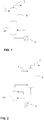
- FIG. 1 shows an evaporator vessel, VK, at the upper end of which a stripping column K connects, such that the Evaporator VK and the stripping column K form a single apparatus.
- a sump evaporator is provided at the lower end of the evaporator vessel VK.
- the stripping column K is fed in the upper region thereof the liquid crude C 4 cut as stream 1, and at the top of the stripping column K, the purified crude C 4 cut , stream 2, deducted.
- Fig. 2 shows the schematic representation of another preferred embodiment in which the evaporator boiler VK and the stripping column K are formed as separate apparatus, and wherein a direct gas and liquid exchange at the upper end of the evaporator vessel VK is provided with the stripping column K.
- the evaporator boiler VK is equipped with a sump evaporator S.
- the stripping column K is fed in the upper region thereof the liquid C 4 cut as stream 1 and withdrawn as overhead stream of the vaporized purified crude C 4 cut , stream 2.
- the starting point is a crude liquid C 4 cut as feed stream for a 100 kt / year plant containing 200 ppm of propane, 400 ppm of propene, 300 ppm of propadiene, 400 ppm of propyne, 2.0% of n-butane, 6.0 % iso-butane, 19.0% n-butene, 28.3% iso-butene, 5.5% trans-2-butene, 4.4% cis-2-butene, 39.0% butadiene-1.3 , 0.2% butadiene-1,2, 1200 ppm butyn-1, 4500 ppm vinyl acetylene and 1000 ppm iso-pentane, 3-methylbutene-1 and 2-methylbutene-2, in each case based on the total weight of the feed stream.
- C 4 oligomers and polymers can be contained in the% range.
- the above crude C 4 cut is subjected to a pre-purification, for comparison in a plant with a distillation column in which the C 3 hydrocarbons are removed overhead and the remaining components are withdrawn via the bottom whereupon the bottom stream is fed to an evaporator vessel for the purpose of separating off the components boiling high in relation to 1,3-butadiene, ie an apparatus with a single separation stage.
- the crude C 4 stream depleted in C 3 components is virtually completely vaporized and discharged under flow control so that the C 5 components which boil over 1,3-butadiene do not exceed 5% by weight in the remaining liquid fraction.
- Based on the total weight supplied to the evaporator vessel raw C 4 cut to the loss of C 4 components in liquid residue to keep small.
- the proportion of oligomers and polymers contained in the liquid residue is significantly greater because of the lower vapor pressure.
- the liquid stream remaining in the evaporator vessel is discharged as purge stream.
- the same crude C 4 cut is fed as feed stream to an evaporator vessel VK, on which a stripping column K is set up with 5 theoretical plates, to which the liquid C 4 cut 1 is fed in the upper region and from the top End of the same is withdrawn from the gaseous purified crude C 4 cut 2, wherein the stripping column K is operated without a condenser at the top of the column.
- a stripping column K is set up with 5 theoretical plates, to which the liquid C 4 cut 1 is fed in the upper region and from the top End of the same is withdrawn from the gaseous purified crude C 4 cut 2, wherein the stripping column K is operated without a condenser at the top of the column.
- the residue stream (from the evaporator vessel) is according to the prior art 160 kg / h, with a proportion of 1,3-butadiene of 38.6 wt .-%.
- a purified crude C 4 cut with a higher degree of purity, compared to the method of the prior art is separated by the novel process.
- ppm C 5 components additional proportions of C 6 components as well as oligomers and polymers may come into consideration, which are not taken into consideration here
- only 55.1 kg / h of C 5 components of the extractive distillation are fed in.
- the loss of desired product 1,3-butadiene is thus greater by about 192 t / year in the process according to the prior art than in the process according to the invention.
Landscapes
- Chemical & Material Sciences (AREA)
- Oil, Petroleum & Natural Gas (AREA)
- Engineering & Computer Science (AREA)
- Chemical Kinetics & Catalysis (AREA)
- General Chemical & Material Sciences (AREA)
- Organic Chemistry (AREA)
- Organic Low-Molecular-Weight Compounds And Preparation Thereof (AREA)
- Production Of Liquid Hydrocarbon Mixture For Refining Petroleum (AREA)
Description
- Die Erfindung betrifft ein Verfahren zur Bereitstellung eines dampfförmigen gereinigten Roh-C4-Schnittes als Einsatzstrom für eine Extraktivdestillation mit einem selektiven Lösungsmittel.
- Der Begriff C4-Schnitt bezeichnet Gemische von Kohlenwasserstoffen mit überwiegend 4 Kohlenstoffatomen pro Molekül. C4-Schnitte werden beispielsweise bei der Herstellung von Ethylen und/oder Propylen durch thermisches Spalten, üblicherweise in Steamcrackern, insbesondere Naphtha-Crackern oder FCC-Crackern (Fluidized Catalytic Cracking) einer Petroleumfraktion, wie verflüssigtes Petroleumgas, Leichtbenzin oder Gasöl, erhalten. Weiterhin werden C4-Schnitte bei der katalytischen Dehydrierung von n-Butan und/oder n-Buten erhalten. C4Schnitte enthalten in der Regel Butane, Butene, 1,3-Butadien, kleine Mengen an C3- und C4-Acetylenen, 1,2-Butadien und C5+-Kohlenwasserstoffe.
- Die Auftrennung von C4-Schnitten ist wegen der geringen Unterschiede in den relativen Flüchtigkeiten der Komponenten ein kompliziertes destillationstechnisches Problem. Daher wird die Auftrennung durch eine sogenannte Extraktivdestillation durchgeführt, d.h. eine Destillation unter Zugabe eines selektiven Lösungsmittels (auch als Extraktionsmittel bezeichnet), das einen höheren Siedepunkt als das aufzutrennende Gemisch aufweist und das die Unterschiede in den relativen Flüchtigkeiten der aufzutrennenden Komponenten erhöht.
- Es sind eine Vielzahl von Verfahren zur Auftrennung von C4-Schnitten mittels Extraktivdestillation unter Verwendung von selektiven Lösungsmitteln bekannt. Ihnen ist gemeinsam, dass sich durch Gegenstromführung des aufzutrennenden C4-Schnittes in Dampfform mit dem flüssigen selektiven Lösungsmittel bei geeigneten thermodynamischen Bedingungen, in der Regel bei niedrigen Temperaturen, häufig im Bereich von 20 bis 80 °C und bei moderaten Drücken, häufig bei Normaldruck bis 6 bar, das selektive Lösungsmittel mit den Komponenten aus dem C4-Schnitt belädt, zu denen es eine höhere Affinität hat, wogegen die Komponenten, zu denen das selektive Lösungsmittel eine geringere Affinität hat, in der Dampfphase verbleiben und als Kopfstrom abgezogen werden. Aus dem beladenen Lösungsmittelstrom werden anschließend unter geeigneten thermodynamischen Bedingungen, d.h. bei höherer Temperatur und/oder niedrigerem Druck gegenüber dem ersten Verfahrensschritt, in einem oder mehreren weiteren Verfahrensschritten die Komponenten fraktioniert aus dem selektiven Lösungsmittel freigesetzt.
- Roh-C4-Schnitte enthalten Verunreinigungen, die in der Extraktivdestillation zu Problemen führen würden, insbesondere Schaumbildung des Lösungsmittels und Apparate-Fouling, so dass diese eben vor der Zuführung des Roh-C4-Schnittes zur Extraktivdestillation abgetrennt werden müssen, um einen zuverlässigen Betrieb der Extraktivdestillation sicherzustellen.
- Verunreinigungen, die zu den obigen Problemen führen, sind insbesondere gegenüber 1,3-Butadien höher siedende Komponenten, darunter besonders C5+-Kohlenwasserstoffe (überwiegend Kohlenwasserstoffe mit 5 oder mehr Kohlenstoffatomen pro Molekül, Isopren, C4-Oligomere und -Polymere, d.h. Oligomere und gegebenenfalls Polymere des Butadiens mit der Formel (C4H6)n, wobei n größer oder gleich 2 ist. Der Anteil der C5+-Kohlenwasserstoffe in C4-Schnitten ist insbesondere abhängig von den Betriebsbedingungen beim thermischen Spalten und beträgt bis zu 1000 Gew.-ppm oder auch bis zu 5000 Gew.-ppm, im Einzelfall bis zu 1 Gew.-%, bezogen auf das Gesamtgewicht des Roh-C4-Schnittes. Die C4-Oligomere und -Polymere bilden sich insbesondere durch Lagerung und Transport; ihr Anteil ist daher überwiegend von den Lager- und Transportbedingungen abhängig, insbesondere Temperatur, Dauer, Inertisierungsgrad der Atmosphäre unter der die Lagerung und/oder der Transport stattfindet.
- Darüber hinaus können auch C3-Kohlenwasserstoffe, d.h. Kohlenwasserstoffe mit drei Kohlenstoffatomen pro Molekül, der Extraktivdestillation zu Problemen führen; hierbei handelt es sich insbesondere um Methylacetylen, das eine ähnliche Affinität zu den üblicherweise eingesetzten selektiven Lösungsmitteln wie 1,3-Butadien aufweist. Der Anteil der C3-Kohlenwasserstoffe soll daher im Feedstrom zur Extraktivdestillation auf maximal 50 Gew.-ppm, bezogen auf das Gesamtgewicht des Feedstroms, begrenzt werden.
- Die obigen Aufgaben zur Vorreinigung des Feedstroms zur Extraktivdestillation von Roh-C4-Schnitten werden bislang in unterschiedlicher Weise gelöst: nach einer bekannten Fahrweise werden in einer der Extraktivdestillation vorgeschalteten Destillationskolonne werden C3-Kohlenwasserstoffe über Kopf abgetrennt und die übrigen Komponenten über Sumpf abgezogen. Der Sumpfstrom wird anschließend zwecks Abtrennung der gegenüber 1,3-Butadien hochsiedenden Komponenten einem Verdampferkessel zugeführt, d.h. einem Apparat mit einer einzigen Trennstufe. Im Verdampferkessel wird der mit C3-Komponenten abgereicherte Roh-C4-Strom nahezu vollständig verdampft, und zwar mengenstromgeregelt, so dass die gegenüber 1,3-Butadien hochsiedenden Komponenten im verbleibenden flüssigen Anteil nicht über 5 Gew.-%, insbesondere nicht über 1 Gew.-%, oder auch nicht über 0,1 Gew.-%, bezogen auf das Gesamtgewicht des dem Verdampferkessel zugeführten Roh-C4-Schnittes liegen. Der im Verdampferkessel verbleibende Flüssigkeitsstrom wird als Purgestrom ausgeschleust. Nachteilig ist hierbei jedoch, dass über den Purgestrom zusammen mit den Hochsiedern hohe Anteile an Wertstoffen, C4-Kohlenwasserstoffe, mit ausgeschleust werden.
- Die
US 4,419,188 A beschreibt ein Verfahren zur Extraktivdestillation in einer Vielzahl von Destillationskolonnen, worin eine Vielzahl von thermisch gekoppelten Extraktivdestillationsschritten durchgeführt werden. - Es war demgegenüber Aufgabe der Erfindung, ein Verfahren zur Verfügung zu stellen, wonach die in der Extraktivdestillation störenden Nebenkomponenten zu Roh-C4-Schnitten in technisch einfacher Weise, mit niedrigen Investitions- und Energiekosten abgetrennt werden können, wodurch die Standzeit der Extraktivdestillationskolonne erhöht wird.
- Diese Aufgabe wird gelöst durch ein Verfahren zur Bereitstellung eines dampfförmigen gereinigten Roh-C4-Schnittes als Einsatzstrom für eine Extraktivdestillation mit einem selektiven Lösungsmittel,
- ausgehend von einem flüssigen Roh-C4-Schnitt als Feedstrom, enthaltend neben Butanen, Butenen und 1,3-Butadien C3-Kohlenwasserstoffe, C4-Oligomere und - Polymere, sowie C5+-Kohlenwasserstoffe, wobei der gereinigte dampfförmige Roh-C4-Schnitt
- weniger als zwei Drittel der im Feedstrom enthaltenden C5+-Kohlenwasserstoffe und
- weniger als 5 Gew.-% der im Feedstrom enthaltenen C4-Oligomere und -Polymere
- 1) Abtrennung der C4-Oligomere und -Polymere sowie der C5+-Kohlenwasserstoffe, jeweils bis auf die vorstehend für den dampfförmigen gereinigten Roh-C4-Schnitt angegebenen Restgehalte, und
- 2) Verdampfen des flüssigen Roh-C4-Schnittes in einem Verdampferkessel
- Es wurde gefunden, dass es möglich ist, in technisch einfacher und energetisch wenig aufwändiger Weise die Hochsiederabtrennung im Verdampferkessel zu erhöhen und dabei gleichzeitig den Verlust an C4-Kohlenwasserstoffen über den Purgestrom aus dem Verdampferkessel zu reduzieren, indem dem Verdampferkessel eine Abtriebskolonne zugeordnet wird.
- Hierbei ist es möglich, insbesondere für den Bau von Neuanlagen, die Abtriebskolonne auf den Verdampferkessel aufzusetzen, das heißt Verdampferkessel und Abtriebskolonne in einen einzigen Apparat zu integrieren.
- In einer anderen Ausführungsform, insbesondere für bestehende Anlagen, ist es auch möglich, dem Verdampferkessel eine Abtriebskolonne beizuordnen, das heißt Verdampferkessel und Abtriebskolonne als getrennte Apparate vorzusehen.
- Verdampferkessel sind in der Verfahrenstechnik bekannte einfache Apparate. Sie umfassen in der Regel einen Kessel, in dem sich eine Gasphase von einer Flüssigphase trennen kann, sowie eine Wärmetauscher, der innerhalb oder außerhalb des Kessels angeordnet ist.
- Erfindungsgemäß wird dem Verdampferkessel eine Abtriebskolonne zugeordnet.
- Da die Abtriebskolonne und der Verdampferkessel lediglich zur Abreicherung an Hochsiedern vorgesehen ist, ist es möglich die Abtriebskolonne in einfacher Weise, ohne Kondensator am Kolonnenkopf, zu betreiben.
- Ein typischer Roh-C4-Schnitt aus einem Naphtha Cracker weist die folgende Zusammensetzung in Gewichtsprozenten auf:
Propan 0 - 0,5 Propen 0 - 0,5 Propadien 0 - 0,5 Propin 0 - 0,5 n-Butan 3 - 10 i-Butan 1 - 3 1-Buten 10 - 20 i-Buten 10 - 30 trans-2-Buten 2 - 8 cis-2-Buten 2 - 6 1,3-Butadien 35 - 65 1,2-Butadien 0,1 -1 Ethylacetylen 0,1 - 2 Vinylacetylen 0,1 - 3 C5 0 - 0,5 - Roh-C4-Schnitte aus Naphtha-Crackern enthalten somit überwiegend Butane, Butene und 1,3-Butadien. Darüber hinaus sind geringe Mengen an sonstigen Kohlenwasserstoffen enthalten. C4-Acetylene sind häufig bis zu einem Anteil von 5 Gew.-% oder auch bis zu 2 Gew.-% enthalten.
- Für die eingangs definierte Extraktivdestillation kommen als selektive Lösungsmittel generell Substanzen oder Gemische in Frage, die einen höheren Siedepunkt als das aufzutrennende Gemisch sowie eine größere Affinität zu konjugierten Doppelbindungen und Dreifachbindungen als zu einfachen Doppelbindungen sowie Einfachbindungen aufweisen, bevorzugt dipolare, besonders bevorzugt dipolaraprotische Lösungsmittel. Aus apparatetechnischen Gründen werden wenig oder nicht korrosive Substanzen bevorzugt.
- Geeignete selektive Lösungsmittel für das erfindungsgemäße Verfahren sind zum Beispiel Butyrolacton, Nitrile wie Acetonitril Propionitril, Methoxypropionitril, Ketone wie Aceton, Furfurol, N-alkylsubstituierte niedere aliphatische Säureamide, wie Dimethylformamid, Diethylformamid, Dimethylacetamid, Diethylacetamid, N-Formylmorpholin, N-alkylsubstituierte cyclische Säureamide (Lactame) wie N-Alkylpyrrolidone, insbesondere N-Methylpyrrolidon. Im Allgemeinen werden N-alkylsubstituierte niedere aliphatische Säureamide oder N-alkylsubstituierte cyclische Säureamide verwendet. Besonders vorteilhaft sind Dimethylformamid, Acetonitril, Furfurol und insbesondere N-Methylpyrrolidon.
- Es können jedoch auch Mischungen dieser Lösungsmittel untereinander, zum Beispiel von N-Methylpyrrolidon mit Acetonitril, Mischungen dieser Lösungsmittel mit Colösungsmitteln wie Wasser und/oder tert.-Butylether, zum Beispiel Methyl-tert.-butylether, Ethyl-tert.-butylether, Propyl-tert.-butylether, n- oder iso-Butyl-tert.-butylether eingesetzt werden.
- Besonders geeignet ist N-Methylpyrrolidon, bevorzugt in wässriger Lösung, insbesondere mit 8 bis 10 Gew.-% Wasser, besonders bevorzugt mit 8,3 Gew.-% Wasser.
- Um Probleme in der Extraktivdestillation zu vermeiden, soll derselben als Einsatzstrom ein dampfförmiger gereinigter Roh-C4-Schnitt zugeführt werden, der weniger als als 50
- Gew.-ppm C3-Kohlenwasserstoffe, bezogen auf das Gesamtgewicht des gereinigten dampfförmigen Roh-C4-Schnittes, weniger als zwei Drittel der im Feedstrom enthaltenden C5+-Kohlenwasserstoffe und weniger als 5 Gew.-% der im Feedstrom enthaltenen C4-Oligomere und -Polymere enthält.
- Es wurde gefunden, dass es möglich ist, die Hochsiederabtrennung in einfacher Weise zu verbessern, indem dem Verdampferkessel eine Abtriebskolonne zugeordnet wird.
- Darüber hinaus ist im erfindungsgemäßen Verfahren die Abtrennung von gegenüber 1,3-Butadien hochsiedenden Komponenten aus dem C4-Schnitt mit wesentlich weniger Verlust an Wertprodukt, C4-Kohlenwasserstoffen möglich.
- Bevorzugt werden die C3-Kohlenwasserstoffe im dampfförmigen gereinigten Roh-C4-Schnitt auf weniger als 10 Gew.-ppm, bezogen auf das Gesamtgewicht des dampfförmigen gereinigten Roh-C4-Schnittes, oder auch weiter bevorzugt auf weniger als 4 Gew.-ppm, in einer dem Verdampferkessel vorgeschalteten Destillationskolonne abgereichert.
- Weiter bevorzugt werden die C5+-Kohlenwasserstoffe im dampfförmigen gereinigten Roh-C4-Schnitt auf weniger als die Hälfte der im Feedstrom enthaltenen C5+-Kohlenwasserstoffe abgereichert.
- Die Abtriebskolonne wird bevorzugt bei einem Kopfdruck im Bereich von 3 bis 7 bar absolut, weiter bevorzugt bei einem Kopfdruck im Bereich von 4,5 bis 5,5 bar absolut, betrieben.
- Die Abtriebskolonne weist insbesondere 1 bis 15 theoretische Böden auf.
- Die Erfindung wird im Folgenden mit einer Zeichnung sowie von Ausführungsbeispielen näher erläutert.
- Die Zeichnungen zeigen im Einzelnen
-
Fig.1 eine schematische Darstellung des Verdampferkessels mit aufgesetzter Abtriebskolonne und -
Fig. 2 eine schematische Darstellung eines Verdampferkessels mit beigeordneter Abtriebskolonne. - Die schematische Darstellung in
Fig. 1 zeigt einen Verdampferkessel, VK, an dessen oberen Ende sich eine Abtriebskolonne K anschließt, dergestalt, dass der Verdampferkessel VK und die Abtriebskolonne K einen einzigen Apparat bilden. Am unteren Ende des Verdampferkessels VK ist ein Sumpfverdampfer vorgesehen. - Der Abtriebskolonne K wird im oberen Bereich derselben der flüssige Roh-C4-Schnitt als Strom 1 zugeführt, und am Kopf der Abtriebskolonne K der gereinigte Roh-C4-Schnitt, Strom 2, abgezogen.
-
Fig. 2 zeigt die schematische Darstellung einer weiteren bevorzugten Ausführungsvariante, bei der der Verdampferkessel VK und die Abtriebskolonne K als getrennte Apparate ausgebildet sind, und wobei ein direkter Gas- und Flüssigkeitsaustausch am oberen Ende des Verdampferkessels VK mit der Abtriebskolonne K vorgesehen ist. - Der Verdampferkessel VK ist mit einem Sumpfverdampfer S ausgestattet.
- Der Abtriebskolonne K wird im oberen Bereich derselben der flüssige C4-Schnitt als Strom 1 zugeführt und als Kopfstrom der dampfförmige gereinigte Roh-C4-Schnitt, Strom 2, abgezogen.
- Ausgegangen wird von einem flüssigen Roh-C4-Schnitt als Feedstrom für eine 100 kt/Jahr-Anlage, enthaltend 200 ppm Propan, 400 ppm Propen, 300 ppm Propadien, 400 ppm Propin, 2,0 % n-Butan, 6,0 % iso-Butan, 19,0 % n-Buten, 28,3 % iso-Buten, 5,5 % trans-2-Buten, 4,4 % cis-2-Buten, 39,0 % Butadien-1,3, 0,2 % Butadien-1,2, 1200 ppm Butin-1, 4500 ppm Vinylacetylen und je 1000 ppm iso-Pentan, 3-Methylbuten-1 und 2-Methylbuten-2, jeweils bezogen auf das Gesamtgewicht des Feedstromes. C4-Oligomere und Polymere können je nach Lager und Transportbedingungen im %-Bereich enthalten sein. Um in einer Extraktivdestillation als Feedstrom eingesetzt werden zu können, wird der obige Roh-C4-Schnitt einer Vorreinigung unterworfen, zum Vergleich in einer Anlage mit einer Destillationskolonne, in der die C3-Kohlenwasserstoffe über Kopf abtrennt und die übrigen Komponenten über Sumpf abgezogen werden, worauf der Sumpfstrom zwecks Abtrennung der gegenüber 1,3-Butadien hochsiedenden Komponenten einem Verdampferkessel zugeführt wird, d. h. einem Apparat mit einer einzigen Trennstufe. Im Verdampferkessel wird der an C3-Komponenten abgereicherte Roh-C4-Strom nahezu vollständig verdampft, und mengenstromgeregelt ausgeschleust, so dass die gegenüber 1,3-Butadien hochsiedenden C5-Komponenten im verbleibenden flüssigen Anteil nicht über 5 Gew.-%, bezogen auf das Gesamtgewichts dem Verdampferkessel zugegeführten Roh-C4-Schnittes, liegen, um den Verlust an C4-Komponenten im flüssigen Rückstand klein zu halten. Der Anteil der im flüssigen Rückstand enthaltenen Oligomere und Polymere ist wegen des geringeren Dampfdruckes deutlich größer. Der im Verdampferkessel verbleibende Flüssigkeitsstrom wird als Purgestrom ausgeschleust.
- Nach dem erfindungsgemäßen Beispiel wird derselbe Roh-C4-Schnitt als Feedstrom einem Verdampferkessel VK zugeführt, auf den eine Abtriebskolonne K mit 5 theoretischen Trennstufen aufgesetzt ist, der der flüssige C4-Schnitt 1 im oberen Bereich derselben zugeführt wird und aus der am oberen Ende derselben der dampfförmige gereinigte Roh-C4-Schnitt 2 abgezogen wird, wobei die Abtriebskolonne K ohne Kondensator am Kolonnenkopf betrieben wird. Eine derartige Anlage ist schematisch in
Figur 1 dargestellt. - Gemäß dem Stand der Technik werden weniger als 5 % der im C4-Schnitt enthaltenen C5-Komponenten über den Rückstandsstrom (=Purgestrom) abgetrennt, während nach dem erfindungsgemäßen Verfahren mehr als ein Drittel der im Feedstrom enthaltenden C5+-Kohlenwasserstoffe und mehr als 95 Gew.-% der im Feedstrom enthaltenen C4-Oligomere und -Polymere über Sumpf im Rückstandsstrom ausgeschleust werden.
- Der Rückstandsstrom (aus dem Verdampferkessel) beträgt nach dem Stand der Technik 160 kg/h, mit einem Anteil von 1,3-Butadien von 38,6 Gew.-%.
- Dem gegenüber betrug der Rückstandsstrom (Sumpfstrom) aus der Destillationskolonne nach dem erfindungsgemäßen Verfahren zwar ebenfalls 160 kg/h, jedoch mit nur 23 Gew.-% 1,3-Butadien. Die Ausbeute an 1,3-Butadien in der Vordestillation (1,3-Butadien im gereinigten C4-Schnitt bezogen auf 1,3-Butadien im Roh-C4-Schnitt) betrug nach dem Stand der Technik 99,29 %, gegenüber 99,49 % nach dem erfindungsgemäßen Beispiel. Das heißt, nach dem erfindungsgemäßen Verfahren wird eine höhere Ausbeute an Wertprodukt 1,3-Butadien erreicht.
- Als weiterer Vorteil wird nach dem erfindungsgemäßen Verfahren ein gereinigter Roh-C4-Schnitt mit höherem Reinheitsgrad, gegenüber dem Verfahren nach dem Stand der Technik abgetrennt. Bei 32 t/h Roh-C4 Feed mit insgesamt 3000 Gew.-% ppm C5-Komponenten (hinzu können weitere Anteile an C6-Komponenten sowie Oligomere und Polymere kommen, die hier nicht berücksichtigt sind) werden 94,16 kg/h C5-Komponenten gemäß Stand der Technik der Extraktivdestillation zugefahren. Im erfindungsgemäßen Fall werden dagegen nur 55,1 kg/h C5-Komponenten der Extraktivdestillation zugefahren. Da weniger C5-Komponenten aus der Vordestillation der Extraktivdestillation zugeführt werden, verringert sich auch entsprechend in der Extraktivdestillation bzw. der anschließenden Reindestillation der Verlust an 1,3-Butadien. Bezogen auf das Reinprodukt (Rein-1,3-Butadien) aus der gesamten Extraktivdestillation inklusive Vordestillation beträgt die Ausbeute an 1,3-Butadien (gerechnet als 100 % 1,3-Butadien) gemäß Stand der Technik 96,47 % und im erfindungsgemäßen Fall 96,66 %.
- In einer oben angegebenen Großanlage mit 100 kt/a ist der Verlust an Wertprodukt 1,3-Butadien somit um ca. 192 t/Jahr im Verfahren gemäß Stand der Technik größer als im erfindungsgemäßen Verfahren.
- Indem das Lösungsmittel einen geschlossenen Kreislauf bildet, wird durch die vorherige Abtrennung störender Komponenten und Verunreinigungen dasselbe sauber gehalten, wodurch der Regenerieraufwand klein gehalten wird. Gleichzeitig werden die Verschmutzung der Extraktivdestillationsanlage (Fouling der Betten in den Kolonnen) sowie die Schaumbildung niedrig gehalten. Dadurch ist weniger Antischaummittel erforderlich mit entsprechend niedrigeren Kosten. Vermindertes Fouling vermindert den Reinigungsaufwand bei einer Abstellung. Jede Abstellung bedeutet einen Produktionsausfall von für ca. 2 Wochen; dazu addiert sich der Reinigungsaufwand. Dies führt zu Kosten im 7-stelligen Bereich.
dem Verdampferkessel eine Abtriebskolonne mit einer oder mehreren Trennstufen zugeordnet ist, der der flüssige C4-Schnitt im oberen Bereich derselben zugeführt wird, die im unteren Bereich derselben in direktem Gas- und Flüssigkeitsaustausch mit dem Verdampferkessel steht und aus der im oberen Bereich derselben der dampfförmige gereinigte Roh-C4-Schnitt abgezogen wird, wobei die Abtriebskolonne ohne Kondensator am Kolonnenkopf betrieben wird.
Claims (9)
- Verfahren zur Durchführung einer Extraktivdestillation mit einem selektiven Lösungsmittel zur Gewinnung von Roh-1,3-Butadien, mit einem gereinigten dampfförmigen Roh-C4-Schnitt (2) als Einsatzstrom, wobei der gereinigte dampfförmige Roh-C4-Schnitt,
ausgehend von einem flüssigen Roh-C4-Schnitt (1) als Feedstrom, enthaltend neben Butanen, Butenen und 1,3-Butadien C3-Kohlenwasserstoffe, C4-Oligomere und -Polymere, sowie C5+-Kohlenwasserstoffe, in einem Verfahren mit den Verfahrensschritten1) Abtrennung der C4-Oligomere und -Polymere sowie der C5+-Kohlenwasserstoffe, jeweils bis auf die vorstehend für den dampfförmigen gereinigten Roh-C4-Schnitt angegebenen Restgehalte, und2) Verdampfen des flüssigen Roh-C4-Schnittes in einem Verdampferkessel (VK),erhalten wird und wobei der gereinigte dampfförmige Roh-C4-Schnitt- weniger als zwei Drittel der im Feedstrom enthaltenden C5+-Kohlenwasserstoffe und- weniger als 5 Gew.-% der im Feedstrom enthaltenen C4-Oligomere und -Polymereenthält,
dadurch gekennzeichnet, dass
dem Verdampferkessel (VK) eine Abtriebskolonne (K) mit einer oder mehreren Trennstufen zugeordnet ist, der der flüssige C4-Schnitt (1) im oberen Bereich derselben zugeführt wird, die im unteren Bereich derselben in direktem Gas-und Flüssigkeitsaustausch mit dem Verdampferkessel (VK) steht und aus der im oberen Bereich derselben der dampfförmige gereinigte Roh-C4-Schnitt (2) abgezogen wird, wobei die Abtriebskolonne (K) ohne Kondensator am Kolonnenkopf betrieben wird. - Verfahren nach Anspruch 1 dadurch gekennzeichnet, dass die Abtriebskolonne (K) auf den Verdampferkessel aufgesetzt ist.
- Verfahren nach Anspruch 1, dadurch gekennzeichnet, dass die Abtriebskolonne (K) dem Verdampferkessel (VK) als getrennter Apparat beigeordnet ist.
- Verfahren nach einem der Ansprüche 1 bis 3, dadurch gekennzeichnet, dass die C3-Kohlenwasserstoffe im dampfförmigen gereinigten Roh-C4-Schnitt auf weniger als 10 Gew.-ppm, bezogen auf das Gesamtgewicht des dampfförmigen gereinigten Roh-C4-Schnittes in einer dem Verdampferkessel (VK) vorgeschalteten Destillationskolonne, abgereichert werden.
- Verfahren nach Anspruch 4, dadurch gekennzeichnet, dass die C3-Kohlenwasserstoffe im dampfförmigen gereinigten Roh-C4-Schnitt auf weniger als 4 Gew.-ppm, bezogen auf das Gesamtgewicht des dampfförmigen gereinigten Roh-C4-Schnittes, abgereichert werden.
- Verfahren nach einem der Ansprüche 1 bis 5, dadurch gekennzeichnet, dass die C5+-Kohlenwasserstoffe im dampfförmigen gereinigten Roh-C4-Schnitt auf weniger als die Hälfte der im Feedstrom enthaltenen C5+-Kohlenwasserstoffe abgereichert werden.
- Verfahren nach einem der Ansprüche 1 bis 6, dadurch gekennzeichnet, dass die Abtriebskolonne (K) bei einem Kopfdruck im Bereich von 3 bis 7 bar absolut betrieben wird.
- Verfahren nach Anspruch 7, dadurch gekennzeichnet, dass die Abtriebskolonne (K) bei einem Kopfdruck im Bereich von 4,5 bis 5,5 bar absolut betrieben wird.
- Verfahren nach einem der Ansprüche 1 bis 8, dadurch gekennzeichnet, dass die Abtriebskolonne (K) 1 bis 15 theoretische Böden aufweist.
Priority Applications (1)
| Application Number | Priority Date | Filing Date | Title |
|---|---|---|---|
| EP13700159.0A EP2802637B1 (de) | 2012-01-11 | 2013-01-10 | Verfahren zur bereitstellung eines dampfförmigen gereinigten roh-c4-schnittes als einsatzstrom für eine extraktivdestillation mit einem selektiven lösungsmittel |
Applications Claiming Priority (3)
| Application Number | Priority Date | Filing Date | Title |
|---|---|---|---|
| EP12150824 | 2012-01-11 | ||
| PCT/EP2013/050366 WO2013104692A1 (de) | 2012-01-11 | 2013-01-10 | Verfahren zur bereitstellung eines dampfförmigen gereinigten roh-c4-schnittes als einsatzstrom für eine extraktivdestillation mit einem selektiven lösungsmittel |
| EP13700159.0A EP2802637B1 (de) | 2012-01-11 | 2013-01-10 | Verfahren zur bereitstellung eines dampfförmigen gereinigten roh-c4-schnittes als einsatzstrom für eine extraktivdestillation mit einem selektiven lösungsmittel |
Publications (2)
| Publication Number | Publication Date |
|---|---|
| EP2802637A1 EP2802637A1 (de) | 2014-11-19 |
| EP2802637B1 true EP2802637B1 (de) | 2017-03-22 |
Family
ID=47553075
Family Applications (1)
| Application Number | Title | Priority Date | Filing Date |
|---|---|---|---|
| EP13700159.0A Active EP2802637B1 (de) | 2012-01-11 | 2013-01-10 | Verfahren zur bereitstellung eines dampfförmigen gereinigten roh-c4-schnittes als einsatzstrom für eine extraktivdestillation mit einem selektiven lösungsmittel |
Country Status (5)
| Country | Link |
|---|---|
| EP (1) | EP2802637B1 (de) |
| JP (1) | JP6067748B2 (de) |
| KR (1) | KR102049312B1 (de) |
| CN (1) | CN104053752B (de) |
| WO (1) | WO2013104692A1 (de) |
Families Citing this family (2)
| Publication number | Priority date | Publication date | Assignee | Title |
|---|---|---|---|---|
| US11697626B2 (en) | 2018-05-18 | 2023-07-11 | Sabic Global Technologies B.V. | Method of producing a fuel additive with a hydration unit |
| CN113544238B (zh) | 2019-03-08 | 2023-02-28 | 沙特基础工业全球技术有限公司 | 生产燃料添加剂的方法 |
Family Cites Families (9)
| Publication number | Priority date | Publication date | Assignee | Title |
|---|---|---|---|---|
| US2877173A (en) | 1955-03-23 | 1959-03-10 | Standard Oil Co | Hydroforming process |
| US4419188A (en) * | 1980-06-02 | 1983-12-06 | Mccall Thomas F | Thermally coupled extractive distillation process |
| JPS58167683A (ja) * | 1982-03-29 | 1983-10-03 | Nippon Zeon Co Ltd | 抽出蒸留方法 |
| DE10022465A1 (de) * | 2000-05-09 | 2001-11-15 | Basf Ag | Verfahren und Vorrichtung zur Aufarbeitung eines C4-Schnitts aus der Fraktionierung von Erdöl |
| DE10333756A1 (de) * | 2003-07-24 | 2005-02-17 | Basf Ag | Verfahren zur Auftrennung eines Roh-C4-Schnittes |
| DE102004005930A1 (de) * | 2004-02-06 | 2005-08-25 | Basf Ag | Verfahren zur Gewinnung von Roh-1,3-Butadien |
| EP1766310A4 (de) * | 2004-07-06 | 2011-12-28 | Fluor Tech Corp | Konfigurationen und verfahren zur gaskondensatabtrennung aus hochdruck-kohlenwasserstoffgemischen |
| PL2043977T3 (pl) * | 2006-07-12 | 2013-03-29 | Basf Se | Sposób rozdzielania frakcji c4 przez destylację ekstrakcyjną z użyciem selektywnego rozpuszczalnika |
| CN101492335B (zh) * | 2008-01-23 | 2013-07-31 | 中国石油化工股份有限公司 | 综合利用混合碳四的组合方法 |
-
2013
- 2013-01-10 CN CN201380005242.3A patent/CN104053752B/zh active Active
- 2013-01-10 EP EP13700159.0A patent/EP2802637B1/de active Active
- 2013-01-10 JP JP2014551607A patent/JP6067748B2/ja active Active
- 2013-01-10 KR KR1020147021970A patent/KR102049312B1/ko active Active
- 2013-01-10 WO PCT/EP2013/050366 patent/WO2013104692A1/de not_active Ceased
Non-Patent Citations (1)
| Title |
|---|
| None * |
Also Published As
| Publication number | Publication date |
|---|---|
| KR20140120329A (ko) | 2014-10-13 |
| EP2802637A1 (de) | 2014-11-19 |
| CN104053752B (zh) | 2016-08-31 |
| WO2013104692A1 (de) | 2013-07-18 |
| JP2015508409A (ja) | 2015-03-19 |
| CN104053752A (zh) | 2014-09-17 |
| KR102049312B1 (ko) | 2019-11-28 |
| JP6067748B2 (ja) | 2017-01-25 |
Similar Documents
| Publication | Publication Date | Title |
|---|---|---|
| EP2043977B1 (de) | Verfahren zur auftrennung eines c4-schnittes durch extraktivdestillation mit einem selektiven lösungsmittel | |
| EP1501773B1 (de) | Kontinuierliches verfahren zur gewinnung von butenen aus einem c4-schnitt | |
| DE2724365A1 (de) | Verfahren zum trennen eines c tief 4 -kohlenwasserstoffgemisches durch extraktive destillation | |
| EP1628940B1 (de) | Verfahren zur gewinnung von roh-1,3-butadien aus einem c4-schnitt | |
| EP1656334B1 (de) | Verfahren zur auftrennung eines roh-c4-schnittes | |
| DE102010011014A1 (de) | Verfahren und Vorrichtung zur destillativen Gewinnung von Rein-1,3-Butadien aus Roh-1,3-Butadien | |
| EP1718585B1 (de) | Verfahren zur gewinnung von roh-1,3-butadien | |
| DE2911395C2 (de) | Verfahren zur Gewinnung eines konjugierten Diolefins aus einem C↓4↓- oder C↓5↓-Kohlenwasserstoffgemisch | |
| EP0284971B1 (de) | Verfahren zur Gewinnung von 1,3-Butadien | |
| EP2788457B1 (de) | Verfahren zur durchführung einer extraktivdestillation mit einem selektiven lösungsmittel, mit einem gereinigten dampfförmigen roh-c4-schnitt als einsatzstrom | |
| WO2004011407A1 (de) | Verfahren zur aufarbeitung von roh-1,3-butadien | |
| EP3573943B1 (de) | Verfahren zur gewinnung von rein-1,3-butadien | |
| EP2802637B1 (de) | Verfahren zur bereitstellung eines dampfförmigen gereinigten roh-c4-schnittes als einsatzstrom für eine extraktivdestillation mit einem selektiven lösungsmittel | |
| EP0016474B1 (de) | Verfahren zur Gewinnung eines konjugierten Diolefins aus einem C 4- oder C 5-Kohlenwasserstoffgemisch | |
| EP2496539B1 (de) | Verfahren zur auftrennung eines c4-schnittes durch extraktivdestillation mit einem selektiven lösungsmittel | |
| EP3596033B1 (de) | Vereinfachtes verfahren zur gewinnung von rein-1,3-butadien | |
| DE3339157A1 (de) | Verfahren zur gewinnung eines konjugierten diolefins und/oder olefins aus einem c(pfeil abwaerts)4(pfeil abwaerts)- oder c(pfeil abwaerts)5(pfeil abwaerts)-kohlenwasserstoffgemisch | |
| WO2019007781A1 (de) | Verfahren und anlage zur trennung von c4-kohlenwasserstoffen durch extraktive destillation | |
| DE2911393B1 (de) | Verfahren zur Gewinnung eines konjugierten Diolefins aus einem C4- oder C5-Kohlenwasserstoffgemisch | |
| DE3346695A1 (de) | Verfahren zur trennung eines c(pfeil abwaerts)4(pfeil abwaerts)-kohlenwasserstoffgemisches durch extraktivdestillation | |
| DE2911396C2 (de) | Verfahren zur Gewinnung eines konjugierten Diolefins aus einem C↓4↓- oder C↓5↓-Kohlenwasserstoffgemisch |
Legal Events
| Date | Code | Title | Description |
|---|---|---|---|
| PUAI | Public reference made under article 153(3) epc to a published international application that has entered the european phase |
Free format text: ORIGINAL CODE: 0009012 |
|
| 17P | Request for examination filed |
Effective date: 20140811 |
|
| AK | Designated contracting states |
Kind code of ref document: A1 Designated state(s): AL AT BE BG CH CY CZ DE DK EE ES FI FR GB GR HR HU IE IS IT LI LT LU LV MC MK MT NL NO PL PT RO RS SE SI SK SM TR |
|
| DAX | Request for extension of the european patent (deleted) | ||
| GRAP | Despatch of communication of intention to grant a patent |
Free format text: ORIGINAL CODE: EPIDOSNIGR1 |
|
| INTG | Intention to grant announced |
Effective date: 20161208 |
|
| GRAS | Grant fee paid |
Free format text: ORIGINAL CODE: EPIDOSNIGR3 |
|
| GRAA | (expected) grant |
Free format text: ORIGINAL CODE: 0009210 |
|
| AK | Designated contracting states |
Kind code of ref document: B1 Designated state(s): AL AT BE BG CH CY CZ DE DK EE ES FI FR GB GR HR HU IE IS IT LI LT LU LV MC MK MT NL NO PL PT RO RS SE SI SK SM TR |
|
| REG | Reference to a national code |
Ref country code: GB Ref legal event code: FG4D Free format text: NOT ENGLISH |
|
| REG | Reference to a national code |
Ref country code: CH Ref legal event code: EP |
|
| REG | Reference to a national code |
Ref country code: AT Ref legal event code: REF Ref document number: 877769 Country of ref document: AT Kind code of ref document: T Effective date: 20170415 |
|
| REG | Reference to a national code |
Ref country code: IE Ref legal event code: FG4D Free format text: LANGUAGE OF EP DOCUMENT: GERMAN |
|
| REG | Reference to a national code |
Ref country code: DE Ref legal event code: R096 Ref document number: 502013006711 Country of ref document: DE |
|
| REG | Reference to a national code |
Ref country code: NL Ref legal event code: MP Effective date: 20170322 |
|
| PG25 | Lapsed in a contracting state [announced via postgrant information from national office to epo] |
Ref country code: HR Free format text: LAPSE BECAUSE OF FAILURE TO SUBMIT A TRANSLATION OF THE DESCRIPTION OR TO PAY THE FEE WITHIN THE PRESCRIBED TIME-LIMIT Effective date: 20170322 Ref country code: FI Free format text: LAPSE BECAUSE OF FAILURE TO SUBMIT A TRANSLATION OF THE DESCRIPTION OR TO PAY THE FEE WITHIN THE PRESCRIBED TIME-LIMIT Effective date: 20170322 Ref country code: NO Free format text: LAPSE BECAUSE OF FAILURE TO SUBMIT A TRANSLATION OF THE DESCRIPTION OR TO PAY THE FEE WITHIN THE PRESCRIBED TIME-LIMIT Effective date: 20170622 Ref country code: LT Free format text: LAPSE BECAUSE OF FAILURE TO SUBMIT A TRANSLATION OF THE DESCRIPTION OR TO PAY THE FEE WITHIN THE PRESCRIBED TIME-LIMIT Effective date: 20170322 Ref country code: GR Free format text: LAPSE BECAUSE OF FAILURE TO SUBMIT A TRANSLATION OF THE DESCRIPTION OR TO PAY THE FEE WITHIN THE PRESCRIBED TIME-LIMIT Effective date: 20170623 |
|
| REG | Reference to a national code |
Ref country code: LT Ref legal event code: MG4D |
|
| PG25 | Lapsed in a contracting state [announced via postgrant information from national office to epo] |
Ref country code: BG Free format text: LAPSE BECAUSE OF FAILURE TO SUBMIT A TRANSLATION OF THE DESCRIPTION OR TO PAY THE FEE WITHIN THE PRESCRIBED TIME-LIMIT Effective date: 20170622 Ref country code: RS Free format text: LAPSE BECAUSE OF FAILURE TO SUBMIT A TRANSLATION OF THE DESCRIPTION OR TO PAY THE FEE WITHIN THE PRESCRIBED TIME-LIMIT Effective date: 20170322 Ref country code: SE Free format text: LAPSE BECAUSE OF FAILURE TO SUBMIT A TRANSLATION OF THE DESCRIPTION OR TO PAY THE FEE WITHIN THE PRESCRIBED TIME-LIMIT Effective date: 20170322 Ref country code: LV Free format text: LAPSE BECAUSE OF FAILURE TO SUBMIT A TRANSLATION OF THE DESCRIPTION OR TO PAY THE FEE WITHIN THE PRESCRIBED TIME-LIMIT Effective date: 20170322 |
|
| PG25 | Lapsed in a contracting state [announced via postgrant information from national office to epo] |
Ref country code: NL Free format text: LAPSE BECAUSE OF FAILURE TO SUBMIT A TRANSLATION OF THE DESCRIPTION OR TO PAY THE FEE WITHIN THE PRESCRIBED TIME-LIMIT Effective date: 20170322 |
|
| PG25 | Lapsed in a contracting state [announced via postgrant information from national office to epo] |
Ref country code: RO Free format text: LAPSE BECAUSE OF FAILURE TO SUBMIT A TRANSLATION OF THE DESCRIPTION OR TO PAY THE FEE WITHIN THE PRESCRIBED TIME-LIMIT Effective date: 20170322 Ref country code: SK Free format text: LAPSE BECAUSE OF FAILURE TO SUBMIT A TRANSLATION OF THE DESCRIPTION OR TO PAY THE FEE WITHIN THE PRESCRIBED TIME-LIMIT Effective date: 20170322 Ref country code: CZ Free format text: LAPSE BECAUSE OF FAILURE TO SUBMIT A TRANSLATION OF THE DESCRIPTION OR TO PAY THE FEE WITHIN THE PRESCRIBED TIME-LIMIT Effective date: 20170322 Ref country code: EE Free format text: LAPSE BECAUSE OF FAILURE TO SUBMIT A TRANSLATION OF THE DESCRIPTION OR TO PAY THE FEE WITHIN THE PRESCRIBED TIME-LIMIT Effective date: 20170322 |
|
| PG25 | Lapsed in a contracting state [announced via postgrant information from national office to epo] |
Ref country code: IS Free format text: LAPSE BECAUSE OF FAILURE TO SUBMIT A TRANSLATION OF THE DESCRIPTION OR TO PAY THE FEE WITHIN THE PRESCRIBED TIME-LIMIT Effective date: 20170722 Ref country code: PL Free format text: LAPSE BECAUSE OF FAILURE TO SUBMIT A TRANSLATION OF THE DESCRIPTION OR TO PAY THE FEE WITHIN THE PRESCRIBED TIME-LIMIT Effective date: 20170322 Ref country code: PT Free format text: LAPSE BECAUSE OF FAILURE TO SUBMIT A TRANSLATION OF THE DESCRIPTION OR TO PAY THE FEE WITHIN THE PRESCRIBED TIME-LIMIT Effective date: 20170724 Ref country code: SM Free format text: LAPSE BECAUSE OF FAILURE TO SUBMIT A TRANSLATION OF THE DESCRIPTION OR TO PAY THE FEE WITHIN THE PRESCRIBED TIME-LIMIT Effective date: 20170322 |
|
| REG | Reference to a national code |
Ref country code: DE Ref legal event code: R097 Ref document number: 502013006711 Country of ref document: DE |
|
| PLBE | No opposition filed within time limit |
Free format text: ORIGINAL CODE: 0009261 |
|
| STAA | Information on the status of an ep patent application or granted ep patent |
Free format text: STATUS: NO OPPOSITION FILED WITHIN TIME LIMIT |
|
| PG25 | Lapsed in a contracting state [announced via postgrant information from national office to epo] |
Ref country code: DK Free format text: LAPSE BECAUSE OF FAILURE TO SUBMIT A TRANSLATION OF THE DESCRIPTION OR TO PAY THE FEE WITHIN THE PRESCRIBED TIME-LIMIT Effective date: 20170322 |
|
| 26N | No opposition filed |
Effective date: 20180102 |
|
| PG25 | Lapsed in a contracting state [announced via postgrant information from national office to epo] |
Ref country code: IT Free format text: LAPSE BECAUSE OF FAILURE TO SUBMIT A TRANSLATION OF THE DESCRIPTION OR TO PAY THE FEE WITHIN THE PRESCRIBED TIME-LIMIT Effective date: 20170322 Ref country code: SI Free format text: LAPSE BECAUSE OF FAILURE TO SUBMIT A TRANSLATION OF THE DESCRIPTION OR TO PAY THE FEE WITHIN THE PRESCRIBED TIME-LIMIT Effective date: 20170322 |
|
| REG | Reference to a national code |
Ref country code: CH Ref legal event code: PL |
|
| GBPC | Gb: european patent ceased through non-payment of renewal fee |
Effective date: 20180110 |
|
| PG25 | Lapsed in a contracting state [announced via postgrant information from national office to epo] |
Ref country code: MT Free format text: LAPSE BECAUSE OF FAILURE TO SUBMIT A TRANSLATION OF THE DESCRIPTION OR TO PAY THE FEE WITHIN THE PRESCRIBED TIME-LIMIT Effective date: 20170322 |
|
| PG25 | Lapsed in a contracting state [announced via postgrant information from national office to epo] |
Ref country code: LU Free format text: LAPSE BECAUSE OF NON-PAYMENT OF DUE FEES Effective date: 20180110 Ref country code: FR Free format text: LAPSE BECAUSE OF NON-PAYMENT OF DUE FEES Effective date: 20180131 |
|
| REG | Reference to a national code |
Ref country code: IE Ref legal event code: MM4A |
|
| REG | Reference to a national code |
Ref country code: FR Ref legal event code: ST Effective date: 20180928 |
|
| REG | Reference to a national code |
Ref country code: BE Ref legal event code: MM Effective date: 20180131 |
|
| PG25 | Lapsed in a contracting state [announced via postgrant information from national office to epo] |
Ref country code: GB Free format text: LAPSE BECAUSE OF NON-PAYMENT OF DUE FEES Effective date: 20180110 Ref country code: BE Free format text: LAPSE BECAUSE OF NON-PAYMENT OF DUE FEES Effective date: 20180131 Ref country code: LI Free format text: LAPSE BECAUSE OF NON-PAYMENT OF DUE FEES Effective date: 20180131 Ref country code: CH Free format text: LAPSE BECAUSE OF NON-PAYMENT OF DUE FEES Effective date: 20180131 |
|
| PG25 | Lapsed in a contracting state [announced via postgrant information from national office to epo] |
Ref country code: IE Free format text: LAPSE BECAUSE OF NON-PAYMENT OF DUE FEES Effective date: 20180110 |
|
| REG | Reference to a national code |
Ref country code: AT Ref legal event code: MM01 Ref document number: 877769 Country of ref document: AT Kind code of ref document: T Effective date: 20180110 |
|
| PG25 | Lapsed in a contracting state [announced via postgrant information from national office to epo] |
Ref country code: AT Free format text: LAPSE BECAUSE OF NON-PAYMENT OF DUE FEES Effective date: 20180110 |
|
| PG25 | Lapsed in a contracting state [announced via postgrant information from national office to epo] |
Ref country code: MC Free format text: LAPSE BECAUSE OF FAILURE TO SUBMIT A TRANSLATION OF THE DESCRIPTION OR TO PAY THE FEE WITHIN THE PRESCRIBED TIME-LIMIT Effective date: 20170322 |
|
| PG25 | Lapsed in a contracting state [announced via postgrant information from national office to epo] |
Ref country code: ES Free format text: LAPSE BECAUSE OF FAILURE TO SUBMIT A TRANSLATION OF THE DESCRIPTION OR TO PAY THE FEE WITHIN THE PRESCRIBED TIME-LIMIT Effective date: 20170322 |
|
| PG25 | Lapsed in a contracting state [announced via postgrant information from national office to epo] |
Ref country code: TR Free format text: LAPSE BECAUSE OF FAILURE TO SUBMIT A TRANSLATION OF THE DESCRIPTION OR TO PAY THE FEE WITHIN THE PRESCRIBED TIME-LIMIT Effective date: 20170322 |
|
| PG25 | Lapsed in a contracting state [announced via postgrant information from national office to epo] |
Ref country code: HU Free format text: LAPSE BECAUSE OF FAILURE TO SUBMIT A TRANSLATION OF THE DESCRIPTION OR TO PAY THE FEE WITHIN THE PRESCRIBED TIME-LIMIT; INVALID AB INITIO Effective date: 20130110 |
|
| PG25 | Lapsed in a contracting state [announced via postgrant information from national office to epo] |
Ref country code: CY Free format text: LAPSE BECAUSE OF FAILURE TO SUBMIT A TRANSLATION OF THE DESCRIPTION OR TO PAY THE FEE WITHIN THE PRESCRIBED TIME-LIMIT Effective date: 20170322 Ref country code: MK Free format text: LAPSE BECAUSE OF NON-PAYMENT OF DUE FEES Effective date: 20170322 |
|
| PG25 | Lapsed in a contracting state [announced via postgrant information from national office to epo] |
Ref country code: AL Free format text: LAPSE BECAUSE OF FAILURE TO SUBMIT A TRANSLATION OF THE DESCRIPTION OR TO PAY THE FEE WITHIN THE PRESCRIBED TIME-LIMIT Effective date: 20170322 |
|
| PGFP | Annual fee paid to national office [announced via postgrant information from national office to epo] |
Ref country code: DE Payment date: 20260127 Year of fee payment: 14 |