EP2802724B1 - Feuerschutztür - Google Patents
Feuerschutztür Download PDFInfo
- Publication number
- EP2802724B1 EP2802724B1 EP12824848.1A EP12824848A EP2802724B1 EP 2802724 B1 EP2802724 B1 EP 2802724B1 EP 12824848 A EP12824848 A EP 12824848A EP 2802724 B1 EP2802724 B1 EP 2802724B1
- Authority
- EP
- European Patent Office
- Prior art keywords
- door
- trunnion
- fireproof
- door leaf
- insertion opening
- Prior art date
- Legal status (The legal status is an assumption and is not a legal conclusion. Google has not performed a legal analysis and makes no representation as to the accuracy of the status listed.)
- Active
Links
Images



Classifications
-
- E—FIXED CONSTRUCTIONS
- E05—LOCKS; KEYS; WINDOW OR DOOR FITTINGS; SAFES
- E05D—HINGES OR SUSPENSION DEVICES FOR DOORS, WINDOWS OR WINGS
- E05D7/00—Hinges or pivots of special construction
- E05D7/08—Hinges or pivots of special construction for use in suspensions comprising two spigots placed at opposite edges of the wing, especially at the top and the bottom, e.g. trunnions
- E05D7/081—Hinges or pivots of special construction for use in suspensions comprising two spigots placed at opposite edges of the wing, especially at the top and the bottom, e.g. trunnions the pivot axis of the wing being situated near one edge of the wing, especially at the top and bottom, e.g. trunnions
-
- E—FIXED CONSTRUCTIONS
- E05—LOCKS; KEYS; WINDOW OR DOOR FITTINGS; SAFES
- E05D—HINGES OR SUSPENSION DEVICES FOR DOORS, WINDOWS OR WINGS
- E05D5/00—Construction of single parts, e.g. the parts for attachment
- E05D5/02—Parts for attachment, e.g. flaps
- E05D5/0246—Parts for attachment, e.g. flaps for attachment to glass panels
-
- E—FIXED CONSTRUCTIONS
- E05—LOCKS; KEYS; WINDOW OR DOOR FITTINGS; SAFES
- E05D—HINGES OR SUSPENSION DEVICES FOR DOORS, WINDOWS OR WINGS
- E05D7/00—Hinges or pivots of special construction
- E05D7/10—Hinges or pivots of special construction to allow easy separation or connection of the parts at the hinge axis
-
- E—FIXED CONSTRUCTIONS
- E05—LOCKS; KEYS; WINDOW OR DOOR FITTINGS; SAFES
- E05D—HINGES OR SUSPENSION DEVICES FOR DOORS, WINDOWS OR WINGS
- E05D7/00—Hinges or pivots of special construction
- E05D7/10—Hinges or pivots of special construction to allow easy separation or connection of the parts at the hinge axis
- E05D7/1061—Hinges or pivots of special construction to allow easy separation or connection of the parts at the hinge axis in a radial direction
-
- E—FIXED CONSTRUCTIONS
- E05—LOCKS; KEYS; WINDOW OR DOOR FITTINGS; SAFES
- E05D—HINGES OR SUSPENSION DEVICES FOR DOORS, WINDOWS OR WINGS
- E05D7/00—Hinges or pivots of special construction
- E05D7/12—Hinges or pivots of special construction to allow easy detachment of the hinge from the wing or the frame
-
- E—FIXED CONSTRUCTIONS
- E06—DOORS, WINDOWS, SHUTTERS, OR ROLLER BLINDS IN GENERAL; LADDERS
- E06B—FIXED OR MOVABLE CLOSURES FOR OPENINGS IN BUILDINGS, VEHICLES, FENCES OR LIKE ENCLOSURES IN GENERAL, e.g. DOORS, WINDOWS, BLINDS, GATES
- E06B3/00—Window sashes, door leaves, or like elements for closing wall or like openings; Layout of fixed or moving closures, e.g. windows in wall or like openings; Features of rigidly-mounted outer frames relating to the mounting of wing frames
- E06B3/02—Wings made completely of glass
-
- E—FIXED CONSTRUCTIONS
- E05—LOCKS; KEYS; WINDOW OR DOOR FITTINGS; SAFES
- E05D—HINGES OR SUSPENSION DEVICES FOR DOORS, WINDOWS OR WINGS
- E05D5/00—Construction of single parts, e.g. the parts for attachment
- E05D5/10—Pins, sockets or sleeves; Removable pins
- E05D5/12—Securing pins in sockets, movably or not
- E05D5/125—Non-removable, snap-fitted pins
-
- E—FIXED CONSTRUCTIONS
- E05—LOCKS; KEYS; WINDOW OR DOOR FITTINGS; SAFES
- E05D—HINGES OR SUSPENSION DEVICES FOR DOORS, WINDOWS OR WINGS
- E05D7/00—Hinges or pivots of special construction
- E05D7/10—Hinges or pivots of special construction to allow easy separation or connection of the parts at the hinge axis
- E05D7/1044—Hinges or pivots of special construction to allow easy separation or connection of the parts at the hinge axis in an axial direction
- E05D7/1055—Hinges or pivots of special construction to allow easy separation or connection of the parts at the hinge axis in an axial direction with snap-fitted pins
-
- E—FIXED CONSTRUCTIONS
- E05—LOCKS; KEYS; WINDOW OR DOOR FITTINGS; SAFES
- E05Y—INDEXING SCHEME ASSOCIATED WITH SUBCLASSES E05D AND E05F, RELATING TO CONSTRUCTION ELEMENTS, ELECTRIC CONTROL, POWER SUPPLY, POWER SIGNAL OR TRANSMISSION, USER INTERFACES, MOUNTING OR COUPLING, DETAILS, ACCESSORIES, AUXILIARY OPERATIONS NOT OTHERWISE PROVIDED FOR, APPLICATION THEREOF
- E05Y2600/00—Mounting or coupling arrangements for elements provided for in this subclass
- E05Y2600/50—Mounting methods; Positioning
- E05Y2600/52—Toolless
- E05Y2600/528—Hooking, e.g. using bayonets; Locking
-
- E—FIXED CONSTRUCTIONS
- E05—LOCKS; KEYS; WINDOW OR DOOR FITTINGS; SAFES
- E05Y—INDEXING SCHEME ASSOCIATED WITH SUBCLASSES E05D AND E05F, RELATING TO CONSTRUCTION ELEMENTS, ELECTRIC CONTROL, POWER SUPPLY, POWER SIGNAL OR TRANSMISSION, USER INTERFACES, MOUNTING OR COUPLING, DETAILS, ACCESSORIES, AUXILIARY OPERATIONS NOT OTHERWISE PROVIDED FOR, APPLICATION THEREOF
- E05Y2900/00—Application of doors, windows, wings or fittings thereof
- E05Y2900/10—Application of doors, windows, wings or fittings thereof for buildings or parts thereof
- E05Y2900/13—Type of wing
- E05Y2900/132—Doors
-
- E—FIXED CONSTRUCTIONS
- E06—DOORS, WINDOWS, SHUTTERS, OR ROLLER BLINDS IN GENERAL; LADDERS
- E06B—FIXED OR MOVABLE CLOSURES FOR OPENINGS IN BUILDINGS, VEHICLES, FENCES OR LIKE ENCLOSURES IN GENERAL, e.g. DOORS, WINDOWS, BLINDS, GATES
- E06B5/00—Doors, windows, or like closures for special purposes; Border constructions therefor
- E06B5/10—Doors, windows, or like closures for special purposes; Border constructions therefor for protection against air-raid or other war-like action; for other protective purposes
- E06B5/16—Fireproof doors or similar closures; Adaptations of fixed constructions therefor
- E06B5/164—Sealing arrangements between the door or window and its frame, e.g. intumescent seals specially adapted therefor
Definitions
- the present invention relates to a fireproof or soundproof glass door comprising a pivot hinge for hanging the door leaf in a door opening, comprising a mounting block which is fastenable to the upper side or underside of the door leaf.
- a pivot hinge is a hinge which on the one hand comprises a trunnion (pivot pin), which is fastened either to the door leaf or to the door opening, and on the other hand comprises a socket (bushing), which is respectively arranged either in the door opening or in the door leaf and in which the trunnion can be rotatably arranged.
- Such a translucent door leaf can be made of glass, for example.
- the intention in such doors is that there are no frames, or as few frames as possible, enclosing the door leaf.
- fireproof doors form a fire barrier between various areas for a certain amount of time, which prevents heat transfer.
- the present invention relates to fireproof or soundproof glass doors.
- fireproof glass doors attempts have therefore long been made to find solutions for hanging the glass door leaf in a door opening with as little framework as possible and with a minimal amount of play between the door leaf and the edge of the door opening.
- a major difficulty in this case is that said fireproof doors should preferably meet the standards which apply to fireproof doors. European standards EN 13501 and EN 1634 can be given as a reference for these standards.
- DE 10 2010 017 447 A1 and US 2004/0206007 A1 describe glass doors with pivot hinges which are fireproof in theory, but in practice, however, do not meet the standards which apply to fireproof doors. In this case it is necessary for the door leaf to be at least partially framed. It is also necessary to perforate the door leaf in order to be able to fasten the door fittings thereto.
- DE 41 23 977 discloses a fireproof glass door with a pivot hinge.
- a more aesthetic overall impression is obtained by minimizing the amount of play between the door leaf and the door opening, without perforating the door leaf and without using extra profiles to eliminate the play. Furthermore, there are fewer draughts and less transmission of noise. The space and its associated risk of fire extension are also reduced. The means required to bridge this space in the event of fire in order to be able to ensure fire resistance are therefore limited such that it is no longer necessary to provide a frame around the door leaf for this purpose. It is therefore possible to meet the demands in respect of fire safety, without it being necessary to provide an obvious frame around the door leaf and without it being necessary to perforate the door leaf.
- the second end of the trunnion in order to fasten the trunnion to the mounting block, is freely positionable in the insertion opening in a first position and is displaceable in the insertion opening from said first position to a second position, in which the flange of the trunnion engages behind the flange of the insertion opening.
- the trunnion can more particularly be linearly displaceable in the insertion opening from the first position to the second position.
- the insertion opening is in this case then preferably embodied as a keyhole opening.
- the trunnion can more particularly be rotatable in the insertion opening from the first position to the second position.
- the respective flanges then extend over only part of the respective edges, such that they can be arranged next to one another in the first position (seen in the insertion opening), in which they do not engage with one another and in the second position (seen in the insertion opening) are arranged one behind the other, in order to engage with one another.
- the trunnion more particularly comprises a first trunnion part, which comprises the first end of the trunnion, and a second trunnion part, which comprises the second end of the trunnion, wherein the exterior of the first trunnion part is conical at its other end than the end of the trunnion, wherein the second trunnion part comprises a fitting cavity, the interior of which is conical and is provided with indentations at the second end of the trunnion and wherein the first trunnion part is positionable via its conical end into the fitting cavity of the second trunnion part, in such a way that when the first trunnion part is positioned in the second trunnion part, the flange of the trunnion points outward.
- the trunnion is fastenable in the insertion opening by positioning the second trunnion part with the flange in the insertion opening and subsequently positioning the first trunnion part with its conical end in the fitting cavity of the second trunnion part, in such a way that the flange of the trunnion which points outward engages behind the flange of the insertion opening.
- the door leaf Since use is made of a pivot hinge, and since the mounting block of said pivot hinge is connected to the bracket, the door leaf will either be clamped locally along part of its upper side by the bracket, when the pivot hinge is arranged above the door, or along part of its underside, when the pivot hinge is arranged under the door.
- the door leaf is unperforated.
- a door according to the present invention comprises a bracket for fastening the pivot hinge to the door leaf, wherein said bracket locally clamps the door leaf along part of the upper side or underside thereof and wherein the mounting block is fastenable to or forms part of said bracket.
- the door is fireproof. In a second specific embodiment of a door according to the present invention, the door is soundproof.
- a door according to the present invention is preferably both fireproof and soundproof.
- the bracket comprises a web plate which extends along at least part of a side edge of the door leaf and at least two upright flanges arranged in pairs which extend on both sides of the door leaf in order to clamp the door leaf.
- the web plate Since use is made of a pivot hinge and since the mounting block of said pivot hinge is connected to the bracket, the web plate will extend either at least partially along the upper edge of the door leaf, when the pivot hinge is arranged above the door, or at least partially along the bottom edge of the door leaf, when the pivot hinge is arranged under the door. In order to ensure proper fastening of the door leaf while covering the door leaf as little as possible, the web plate of such a bracket extends further in this direction than the upright flanges.
- the bracket of a fireproof door can also comprise a plurality of upright flanges arranged in pairs which locally clamp the door leaf at a distance from one another.
- the upright flanges of such a bracket having at least two upright flanges arranged in pairs can, if desired, optionally be protected with the aid of swellable material which in turn can be protected by a cover plate, for example, in order to limit heat transfer via the bracket.
- a bracket of a fireproof door according to the invention is preferably made of steel or stainless steel.
- the web plate of an abovementioned bracket is also preferably perforated, in order to limit heat transfer. More specifically, said web plate can be provided with a plurality of rows of perforations extending in the longitudinal direction of the side edge, wherein the perforations of a first row are arranged in a staggered fashion with respect to the perforations of a second row. Such an arrangement of perforations has an insulating effect and ensures that conduction is greatly reduced.
- material which swells under the influence of heat is arranged between the web plate and the door leaf. It is possible to use a strip of material based on graphite, for example, as such swellable material.
- such swellable material In the event of fire, such swellable material swells and ensures good flame-tightness between the bracket and the glass. If perforations are provided in such a bracket, the swellable material can then also swell up in the event of fire and pass through the bracket and (help to) close off the space between the door leaf and the door opening.
- the web plate of a bracket as described above preferably extends over the width of the door leaf.
- the bracket is fastened to the door leaf by means of structural adhesive which is protected by at least one fireproof element.
- Such a structural adhesive ensures that the bracket can be fastened to the door leaf in a particularly firm fashion, without it being necessary to perforate said door leaf in order to fasten the bracket to the door leaf.
- a drawback of such a structural adhesive is that the structural adhesives which are best suited for this purpose will carbonize in the event of fire and ignite, which would compromise the fire resistance of the door. By protecting the structural adhesive from the external surroundings using a fireproof element, it is possible to ensure the required level of fire resistance.
- said fireproof element can more preferably be fireproof adhesive.
- a silicate cube for example, as the fireproof element.
- fireproof adhesive It is possible to select, for example, a high-temperature-resistant two-component epoxy adhesive based on metal as fireproof adhesive.
- An important consideration for such a fireproof adhesive is that it provides the required insulation between the door leaf and the bracket and, at least initially, retains its volume at least partially in the event of fire (it will nevertheless lose its bond). In this way, said fireproof adhesive will, at least initially, form a buffer between the glass and the bracket (which can reach high temperatures) in the event of fire, as a result of which glass breakage is avoided.
- Said fireproof adhesive preferably at least partially retains its adhesive strength at a temperature of 80°C and does not ignite at this temperature.
- metal tape is at least partially applied between the structural adhesive and the door leaf.
- fireproof glass comprising a plurality of layers of glass between which fireproof gel is applied
- said fireproof gel is usually surrounded by a rubber seal which can be damaged by such a structural adhesive.
- a metal tape means that it is possible to protect such a rubber seal from the structural adhesive.
- the door leaf of a glass door according to the present invention can more specifically be made of fire-resistant glass.
- Such fire-resistant glass can comprise a plurality of glass sheets between which fireproof material, such as a fireproof gel, for example, is applied.
- the glass sheets it is possible for the glass sheets to be made from float glass, cast glass, toughened glass, thermally prestressed glass, laminated glass, layered glass, etc., depending on the fire-resistance requirements.
- a fireproof door according to the invention preferably further comprises sheet material with a core based on sodium silicate or based on fireproof graphite, wherein said sheet material extends substantially over the sides of the door opening in order to expand in the event of fire and (help to) close off the space between the door leaf and the door opening.
- At least partially swellable material may be provided along the sides of the door opening, wherein said swellable material is more specifically able to at least partially cover the sheet material with a core based on sodium silicate or based on fireproof graphite.
- the fireproof door (1) illustrated in Figure 1 comprises a door leaf (2) which is hung in a door opening.
- the door is hung with the aid of, on the one hand, a pivot hinge (3) and a bracket (4), being fastening means at the upper side of the door leaf (2), and, on the other hand, a floor spring (19), a bottom support (18) and a bracket (4), being fastening means at the underside of the door leaf (2).
- the pivot hinge (3) and the bracket (4) at the top and the bottom support (18), the bracket (4) and the floor spring (19) at the bottom enable the door leaf (2) to rotate in the door opening between an open position, in which the door opening is open, and a closed position, in which the door leaf (2) extends in the door opening and substantially closes off said door opening.
- the fireproof door (1) illustrated in Figure 1 is a swing door (1), since the door leaf (2) is not prevented from rotating in two directions with respect to the door opening (outward and inward). It is of course also possible to produce a single-action door (1), by arranging the pivot hinge (3) on one side (the front side or the rear side) of the door leaf (2), as a result of which the door leaf (2) can rotate in only one direction with respect to the door opening.
- the axis around which the door leaf (2) can rotate is also located along the left-hand side of the door leaf (2). It is of course also possible to provide an axis of rotation centrally with respect to the door leaf (2) instead of an axis of rotation at one side of the door leaf (2), so that a wider door leaf (2) can rotate about a central axis.
- the fireproof door (1) in Figure 1 extends in the door opening.
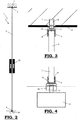
- the sides of the door opening are covered with sheet material (13), which can be seen more clearly in Figures 3 , 5 and 22 .
- Said sheet material (13) comprises a core based on sodium silicate. It is possible, for example, to select sheet material (13) for this purpose which is known under the trade name palusol® and distributed by BASF. Said sheet material (13) will expand in the event of fire and (help to) close off the space between the door leaf (2) and the door opening.
- An important consideration in the case of a fireproof door (1) according to the invention is that there is only a small amount of space between the door leaf (2) and the sides of the door opening, so that said space can be effectively closed off in the event of fire with the aid of swellable material, such as the abovementioned sheet material (13) or some other swellable material (12).
- the absence of fastening means makes it possible to minimize the amount of play between the door leaf (2) and the door opening along the side edges of the door opening.
- the amount of said play is 4 mm in the illustrated embodiment. Solely the abovementioned sheet material (13) is present in this case to close off the space between the door leaf (2) and the door opening in the event of fire.
- Said sheet material (13) can optionally be supplemented by another swellable material (12).
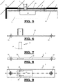
- further swellable material (12) is arranged on the upper side of the door leaf (2) along the upper side of the door opening (see Figure 5 ), where the amount of play between the door leaf (2) and the door opening is somewhat larger because of the presence of the pivot hinge (3), in order to close off the space between the door leaf (2) and the door opening in the event of fire, as discussed in more detail below.
- additional swellable material (12) to be provided in the door opening.
- the amount of play at the upper side is 7 mm.
- the amount of play in the illustrated embodiment is 8 mm.
- the door leaf (2) is made of glass and preferably of fire-resistant/fireproof glass.
- Said fire-resistant/fireproof glass can comprise a plurality of glass sheets between which fireproof material, for example a fireproof gel, is applied.
- the glass sheets can be made of float glass, cast glass, toughened glass, thermally prestressed glass, laminated glass, layered glass, etc.
- the pivot hinge (3) in the illustrated embodiment of a fireproof door (1) is fastened to the door leaf (2) by means of a bracket (4), which can be seen more clearly in Figures 3 and 5 .
- the pivot hinge (3) comprises a mounting block (5) and a trunnion (6) for this purpose.
- the mounting block (5) is fixedly connected to the bracket (4). This can be effected by means of gluing, welding or with the aid of screws, for example.
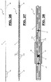
- fastening openings (17) present in the bracket (4) see Figures 27 and 28
- fastening openings (16) present in the mounting block (5) see Figures 8 and 9 ), in order to be able to connect said bracket and mounting block to one another using screws.
- a plate (23) with a socket (7) is arranged in the door opening, in which socket (7) the trunnion (6) of the pivot hinge (3) can be rotatably arranged.
- Said plate (23) with socket (7) is illustrated separately in Figure 6 .
- Fastening openings (24) are provided in the plate (23) of the socket, so that the plate (23) of the socket can be fastened in the door opening by means of screws. It is of course possible to consider alternative fastening methods.
- the trunnion (6) of the first embodiment can be detachably fastened in the corresponding mounting block (5).
- the detachable fastening of said trunnion (6) in the mounting block (5) can be effected, inter alia, by means of a keyhole opening (14) in the mounting block (5) (see Figures 8 and 9 ) and a flange (15) on the cylindrical trunnion (6) (see Figure 7 ), as shown in the first embodiment.
- Said keyhole opening (14) has a relatively wide part (first position) and a relatively narrow part (second position).
- the cylindrical trunnion (6) has a diameter which is at most the same as the width of the relatively narrow part of the keyhole opening (14), while the trunnion flange (15) is relatively wide, but is at most as wide as the relatively wide part of the keyhole opening (14).
- the trunnion (6) is arranged in the socket (7) when said socket (7) has been detached from the mounting block (5).
- the door leaf (2), to which the mounting block (5) is fastened using the bracket (4), is subsequently mounted in the door opening.
- the trunnion (6) is positioned in the relatively wide part of the keyhole opening (14) by means of the flange (15) and displaced in the keyhole opening (14) until the flange (15) of the trunnion (6) becomes fixed behind the flanges (25) which delimit the relatively narrow part of the keyhole opening (14).
- a fixing platelet can optionally be inserted into the relatively wide part of the keyhole opening (14) to prevent the trunnion (6) from sliding back out of the relatively narrow part and becoming detached. This would be possible if the door leaf (2) is in its open state.
- the second embodiment according to the present invention corresponds to the first embodiment according to the present invention, but in this case the trunnion (6) is now provided with an adjusting screw (28).
- the head of said adjusting screw (28) into which a hand tool can be engaged in order to rotate said adjusting screw (28), is situated in the insertion opening (14).
- said adjusting screw (28) in said insertion opening (14) can be reached in order to be rotated from the first position.
- Rotating the adjusting screw (28) makes it possible to adjust the position of the door leaf (2) in the door opening in a horizontal direction.
- the trunnion (6) and mounting block (5) of which are illustrated in Figures 13 to 17 the trunnion (6) is once again substantially cylindrical and in this case has a flange (15) which extends over only half of the periphery of the cylindrical base of the trunnion (6) at the edge of the second end of the trunnion (6).
- an insertion opening (14) is provided which is delimited on one side (the right-hand side in Figures 16 and 17 ) by means of a semi-circular flange (25).
- the trunnion (6) can be positioned in the insertion opening (14) via its second end with its flange (15) facing the side of the insertion opening (14) opposite the side with the flange (25) of the insertion opening (14) (see Figure 16 ).
- the trunnion (6) is subsequently rotated through 180° in the insertion opening (14) until the flange (15) of the trunnion (6) engages below the flange (25) of the insertion opening (14) (see Figure 17 ).
- a fixing platelet in the insertion opening (14) next to the trunnion (6) and the flanges (15, 25) to prevent the trunnion (6) from becoming detached again by rotation.
- said fixing plate In order to release the trunnion (6) again, said fixing plate must be removed again, if necessary, and the trunnion (6) can once again be rotated through 180° until the flanges (15) and (25) no longer engage with one another.
- the trunnion (6) is formed from two parts.
- the first trunnion part (6a) comprises the first end of the trunnion (6). At its other end said trunnion part (6a) is conical.
- the second trunnion part (6b) comprises the second end of the trunnion (6) and is hollow. Said second trunnion part (6b) comprises a conical fitting cavity.
- said second trunnion part (6b) is provided with indentations.
- a lever system (26) is fastened to the plate (23) containing the socket (7) for moving the first trunnion part (6a) with respect to the second trunnion part (6b).
- said lever system (26) By moving the first trunnion part (6a) downward using said lever system (26), as illustrated in Figures 20 and 21 , the first trunnion part (6a) is positioned with its conical end into the fitting cavity of the second trunnion part (6b).
- the flange (15) of the trunnion (6) points outward.
- the mounting block (5) there is an insertion opening which corresponds to the periphery of the flange (15) of the trunnion (6), which insertion opening is provided with a flange (25) around its periphery.
- the trunnion (6) can be fastened in the insertion opening (14) by first positioning the second trunnion part (6b) with the flange (15) in the insertion opening (14) of the mounting block (5) and subsequently positioning the first trunnion part (6a) with its conical end in the fitting cavity of the second trunnion part (6b), in such a way that the flange (15) of the trunnion (6) which points outward engages behind the flange (25) of the insertion opening (14).
- the bracket (4) of the illustrated embodiment of a fireproof door (1) is made of steel.
- Said bracket (4) comprises a web plate (9), which extends along the upper edge of the door leaf (2) and which comprises upright flanges (10) arranged in pairs, which extend on both sides of the door leaf (2), in order to clamp the door leaf (2).
- the bracket (4) in the illustrated embodiment comprises two upright flanges (10) arranged in pairs. It is of course also possible, where necessary (for example owing to strength requirements) or where desired (for example owing to aesthetic considerations), to provide one pair of flanges (10) or several pairs of flanges (10) per bracket (4).
- the web plate (9) of the bracket (4) is provided with a plurality of rows of perforations (11a, 11b) which extend in the longitudinal direction of the bracket (4) (see Figures 15 and 16 ).
- the perforations (11a) of a first row are arranged in a staggered fashion with respect to the perforations (11b) of a second row. In this way, said perforations (11a, 11b) limit convection via the web plate (9) between an area where fire is present and an adjacent area.
- a strip of material (12) which swells under the influence of heat is arranged between the web plate (9) and the door leaf (2), for example swellable material based on graphite.
- said strip of swellable material (12) ensures good insulation between the bracket (4) and the glass of the door leaf (2). In this way, the heat of the bracket (4) is prevented from causing breakage of the glass.
- the perforations (11a, 11b) mean that said swellable material (12) can also easily expand through the perforations (11a, 11b) into the space between the door leaf (2) and the door opening.
- the door leaf (2) is fastened in the flanges (10) by means of structural adhesive (8).
- structural adhesive (8) A prepolymerized polyurethane adhesive and more specifically a two-component sealant based on isocyanate can be used as structural adhesive.
- Such a structural adhesive is known, for example, under the name Quick Bond prepolymer from Veidec®.
- Such a structural adhesive (8) ensures that the bracket (4) can be fastened to the door leaf (2) in a particularly firm fashion, without it being necessary to perforate the door leaf (2) in order to fasten the bracket (4) to the door leaf (2). Since such a structural adhesive (8) carbonizes in the event of fire and will possibly ignite, said adhesive (8) is protected from the external surroundings. This can be effected, for example, with the aid of fireproof adhesive (8). It is possible to use, for example, a high-temperature-resistant two-component epoxy adhesive based on metal as such fireproof adhesive (8). Such a suitable adhesive is known, for example, under the name Technofix from Promante.
- a metal tape is applied, where necessary, between the structural adhesive (8) and the door leaf (2), in order not to damage the rubber seals between the various layers of fireproof glass.
- Other elements which are fastened to the door leaf (2) are also preferably fastened in the same manner, using a combination of structural adhesive (8) and fireproof adhesive (8), in order to avoid perforating the door leaf (2) and to embody the door (1) in a fireproof manner.
- the illustrated door handle (22) for opening and closing the door (1) is therefore also preferably glued to the door leaf (2) using a combination of structural adhesive (8) and fireproof adhesive (8).
- the bracket (4) for fastening the bottom pivot (18) to the door leaf (2) is also preferably fastened to the underside of the door leaf (2) using a combination of structural adhesive (8) and fireproof adhesive (8).
- the bracket (4) for fastening the bottom pivot (18) can be embodied in the same manner as the bracket (4) for fastening the pivot hinge (3) to the upper side of the door leaf (2).
- a strip of fireproof material (12) is applied between the web plate (9) of the bracket (4) and the door leaf (2).
- the flanges (10) are in this case likewise glued to the door leaf (2).
- the bottom pivot (18) can be fixedly attached to the bracket (4) by means of gluing or welding or using screws, for example.
- the bottom pivot (18) is provided in a known manner with an opening (20), in which the shaft (21) of the floor spring (19) can be arranged in a known manner.
Landscapes
- Engineering & Computer Science (AREA)
- Mechanical Engineering (AREA)
- Civil Engineering (AREA)
- Structural Engineering (AREA)
- Special Wing (AREA)
Claims (8)
- Feuerschutz- und/oder Schallschutztür (1), umfassend ein Glastürblatt (2) und umfassend ein Schwenkscharnier (3), zum Einhängen des Glastürblatts (2) in eine Türöffnung, wobei das Schwenkscharnier (3) einen Befestigungsblock (5), der an der Oberseite oder Unterseite des Türblatts (2) befestigbar ist, eine Buchse (7), die in der Kante der Türöffnung befestigbar ist oder darin angeordnet ist, und einen Zapfen (6), der an einem ersten Ende in der Buchse (7) positionierbar ist, um drehbar in der Buchse (7) angeordnet zu werden, und an einem zweiten Ende an dem Befestigungsblock befestigbar ist, umfasst, dadurch gekennzeichnet, dass das Türblatt (2) nicht perforiert ist und eine Halterung (4) zum Befestigen des Schwenkscharniers (3) am Türblatt (2) umfasst, wobei die Halterung (4) das Türblatt (2) lokal entlang eines Teils der Oberseite oder der Unterseite davon einklemmt, dass der Zapfen (6) einen Flansch (15) an seinem zweiten Ende umfasst, der sich zumindest teilweise entlang der Kante des Zapfens (6) an dem zweiten Ende erstreckt, und dass der Befestigungsblock (5) eine Einsatzöffnung (14) umfasst und einen Flansch (25) umfasst, der sich zumindest teilweise entlang der Kante der Einsatzöffnung (14) erstreckt, wobei, im befestigten Zustand des Befestigungsblocks (5), die Einsatzöffnung (14) für den Zapfen (6) nur von der Seite zugänglich ist, die zur Buchse (7) zeigt, und wobei der Zapfen (6) an seinem zweiten Ende von dieser Seite über die Einsatzöffnung (14) an dem Befestigungsblock (5) befestigbar ist, wobei, im befestigten Zustand des Zapfens (6), der Flansch (15) des Zapfens (6) in die Einsatzöffnung (14) hinter dem Flansch (25) der Einsatzöffnung (14) eingreift, wobei, um den Zapfen (6) an dem Befestigungsblock (5) zu befestigen, das zweite Ende des Zapfens (6) in der Einsatzöffnung (14) in einer ersten Position frei positionierbar ist und in der Einsatzöffnung (14) von der ersten Position in eine zweite Position versetzbar ist, in der der Flansch (15) des Zapfens (6) hinter dem Flansch (25) der Einsatzöffnung (14) eingreift und wobei der Befestigungsblock an der Halterung (4) befestigbar ist oder einen Teil derselben bildet.
- Feuerschutz- und/oder Schallschutztür (1) nach Anspruch 1, dadurch gekennzeichnet, dass der Zapfen (6) in der Einsatzöffnung (14) linear von der ersten Position in die zweite Position versetzbar ist.
- Feuerschutz- und/oder Schallschutztür (1) nach Anspruch 2, dadurch gekennzeichnet, dass die Einsatzöffnung (14) als eine Schlüssellochöffnung (14) ausgeführt ist.
- Feuerschutz- und/oder Schallschutztür (1) nach Anspruch 1, dadurch gekennzeichnet, dass der Zapfen (6) in der Einsatzöffnung (14) von der ersten Position in die zweite Position drehbar ist.
- Feuerschutztür (1) nach einem der vorhergehenden Ansprüche, dadurch gekennzeichnet, dass die Halterung (4) ein Stegblech (9) umfasst, das sich entlang zumindest eines Teils einer Seitenkante des Türblatts (2) erstreckt und perforiert ist, und dass die Halterung (4) mindestens zwei aufrechte Flansche (10) umfasst, die in Paaren angeordnet sind, die sich auf beiden Seiten des Türblatts (2) erstrecken, um das Türblatt (2) einzuklemmen.
- Feuerschutztür (1) nach einem der vorhergehenden Ansprüche, dadurch gekennzeichnet, dass die Halterung (4) am Türblatt (2) mittels eines Strukturklebers (8) befestigt wird, der durch feuerfesten Klebstoff (8) geschützt wird.
- Feuerschutztür (1) nach einem der vorhergehenden Ansprüche, dadurch gekennzeichnet, dass die Feuerschutztür (1) Blechmaterial (13) mit einem Kern auf der Basis von Natriumsilikat umfasst, wobei sich das Blechmaterial (13) im Wesentlichen über die Seiten der Türöffnung erstreckt.
- Feuerschutztür (1) nach einem der vorhergehenden Ansprüche, dadurch gekennzeichnet, dass die Feuerschutztür (1) Blechmaterial (13) mit einem Kern auf der Basis von feuerfestem Graphit umfasst, wobei sich das Blechmaterial (13) im Wesentlichen über die Seiten der Türöffnung erstreckt.
Priority Applications (1)
| Application Number | Priority Date | Filing Date | Title |
|---|---|---|---|
| PL12824848T PL2802724T3 (pl) | 2012-01-11 | 2012-12-21 | Drzwi przeciwpożarowe |
Applications Claiming Priority (2)
| Application Number | Priority Date | Filing Date | Title |
|---|---|---|---|
| BE2012/0023A BE1020366A5 (nl) | 2012-01-11 | 2012-01-11 | Brandwerende deur. |
| PCT/IB2012/002775 WO2013104946A1 (en) | 2012-01-11 | 2012-12-21 | Fire door |
Publications (2)
| Publication Number | Publication Date |
|---|---|
| EP2802724A1 EP2802724A1 (de) | 2014-11-19 |
| EP2802724B1 true EP2802724B1 (de) | 2020-04-01 |
Family
ID=47739398
Family Applications (1)
| Application Number | Title | Priority Date | Filing Date |
|---|---|---|---|
| EP12824848.1A Active EP2802724B1 (de) | 2012-01-11 | 2012-12-21 | Feuerschutztür |
Country Status (5)
| Country | Link |
|---|---|
| EP (1) | EP2802724B1 (de) |
| BE (1) | BE1020366A5 (de) |
| DK (1) | DK2802724T3 (de) |
| PL (1) | PL2802724T3 (de) |
| WO (1) | WO2013104946A1 (de) |
Families Citing this family (6)
| Publication number | Priority date | Publication date | Assignee | Title |
|---|---|---|---|---|
| DE202012101540U1 (de) * | 2012-04-25 | 2012-05-23 | Holzbau Schmid Gmbh & Co. Kg | Zargenfreie Brandschutz-Ganzglastür |
| DE202013009165U1 (de) | 2013-10-17 | 2015-01-19 | Promat Gmbh | Rahmenlose Glastür für Brandschutzzwecke |
| JP6209055B2 (ja) * | 2013-10-30 | 2017-10-04 | 三協立山株式会社 | ドア |
| EP3029239B8 (de) * | 2014-12-04 | 2022-04-13 | DORMA-Glas GmbH | Eckbeschlag für vsg-glastürelement |
| CN106014044B (zh) * | 2016-05-24 | 2017-05-31 | 百安力钢结构应用科技有限公司 | 门铰链装置及防火门 |
| WO2026008437A1 (de) | 2024-07-03 | 2026-01-08 | Saint-Gobain Glass France | Wandelement mit befestigungsteil |
Citations (5)
| Publication number | Priority date | Publication date | Assignee | Title |
|---|---|---|---|---|
| DE202671C (de) * | 1900-01-01 | |||
| DE4123977A1 (de) * | 1991-07-19 | 1993-01-21 | Fachverband Glasdach Und Metal | Feuerwiderstandsfaehige glastrennwand |
| DE9414272U1 (de) * | 1993-09-04 | 1994-11-03 | Joh. Vaillant Gmbh U. Co, 42859 Remscheid | Halterung |
| NL9400071A (nl) * | 1994-01-14 | 1995-08-01 | Ums Pastoe B V | Speunscharnier en wandkast voorzien van met dergelijke scharnieren opgehangen deuren. |
| DE10104215A1 (de) * | 2001-01-31 | 2002-08-01 | Haendler Gmbh & Co Kg Elektro | Verfahren zum Befestigen eines schwenkbaren Elektroschrankmoduls in einem Elektroschrank und Scharnierbausatz |
Family Cites Families (6)
| Publication number | Priority date | Publication date | Assignee | Title |
|---|---|---|---|---|
| DE242507C (de) * | ||||
| IT1272061B (it) * | 1993-11-26 | 1997-06-11 | Dierre Spa | Profilato metallico per la costruzione di telai di porte antincendio |
| DE19937835A1 (de) * | 1999-08-13 | 2001-03-15 | Techno Elementebau Leipzig Gmb | Feuerschutzsystem |
| US6966150B2 (en) * | 2003-04-11 | 2005-11-22 | Fanny Chiang | Adjustable automatic positioning hinge for glass doors |
| DE102009048917B3 (de) * | 2009-10-10 | 2010-09-16 | Simonswerk, Gesellschaft mit beschränkter Haftung | Vorrichtung zur Höhenverstellung eines Türbandes |
| DE102010017447A1 (de) * | 2010-06-18 | 2011-12-22 | Theo Schröders | Feuerschutztür |
-
2012
- 2012-01-11 BE BE2012/0023A patent/BE1020366A5/nl active
- 2012-12-21 WO PCT/IB2012/002775 patent/WO2013104946A1/en not_active Ceased
- 2012-12-21 PL PL12824848T patent/PL2802724T3/pl unknown
- 2012-12-21 EP EP12824848.1A patent/EP2802724B1/de active Active
- 2012-12-21 DK DK12824848.1T patent/DK2802724T3/da active
Patent Citations (5)
| Publication number | Priority date | Publication date | Assignee | Title |
|---|---|---|---|---|
| DE202671C (de) * | 1900-01-01 | |||
| DE4123977A1 (de) * | 1991-07-19 | 1993-01-21 | Fachverband Glasdach Und Metal | Feuerwiderstandsfaehige glastrennwand |
| DE9414272U1 (de) * | 1993-09-04 | 1994-11-03 | Joh. Vaillant Gmbh U. Co, 42859 Remscheid | Halterung |
| NL9400071A (nl) * | 1994-01-14 | 1995-08-01 | Ums Pastoe B V | Speunscharnier en wandkast voorzien van met dergelijke scharnieren opgehangen deuren. |
| DE10104215A1 (de) * | 2001-01-31 | 2002-08-01 | Haendler Gmbh & Co Kg Elektro | Verfahren zum Befestigen eines schwenkbaren Elektroschrankmoduls in einem Elektroschrank und Scharnierbausatz |
Also Published As
| Publication number | Publication date |
|---|---|
| WO2013104946A1 (en) | 2013-07-18 |
| BE1020366A5 (nl) | 2013-08-06 |
| PL2802724T3 (pl) | 2020-11-02 |
| DK2802724T3 (da) | 2020-05-18 |
| EP2802724A1 (de) | 2014-11-19 |
Similar Documents
| Publication | Publication Date | Title |
|---|---|---|
| WO2013104946A1 (en) | Fire door | |
| JP5960977B2 (ja) | 防火ドア | |
| SI20430A (sl) | Protipožarna stena | |
| US20140360124A1 (en) | Windows and doors assembly structure having a joint portion of 45 degrees | |
| WO2003072888A2 (en) | Fire-resistant wood assemblies for building | |
| EP0927809B1 (de) | Brandschutz-Bauelement | |
| HU212006B (en) | Fire-resistant glass partition | |
| EP2460970A1 (de) | Paneel eines Sektionaltors mit einer Fensteranordnung und Verfahren zur Montage des Paneels | |
| KR20220013883A (ko) | 이중 단열 방화 유리문 | |
| JP2024015203A (ja) | 建具 | |
| JP6001251B2 (ja) | 開口部装置、防火部材 | |
| JP6917854B2 (ja) | 建具 | |
| JP6980491B2 (ja) | 建具 | |
| CN214273319U (zh) | 隔音隔热门窗安装边框构件及铝合金门窗 | |
| CN215907115U (zh) | 一种内置有玻璃百叶的幕墙系统 | |
| JP2017025555A (ja) | 建具 | |
| EP2770153B1 (de) | Gehäusestruktur für eine Abschirmvorrichtung | |
| JP7340425B2 (ja) | 障子 | |
| JP7114493B2 (ja) | 建具 | |
| GB2432179A (en) | A fire resistant vision panel having a blind | |
| CN218912717U (zh) | 一种便于安装的防火门 | |
| CN113294068B (zh) | 一种防火玻璃挡钩 | |
| CN215169480U (zh) | 一种新型偏心摇臂结构的超大水晶硅防火玻璃门 | |
| JP7583579B2 (ja) | 建具 | |
| CN222745974U (zh) | 一种便于维修的铝合金耐火窗 |
Legal Events
| Date | Code | Title | Description |
|---|---|---|---|
| PUAI | Public reference made under article 153(3) epc to a published international application that has entered the european phase |
Free format text: ORIGINAL CODE: 0009012 |
|
| 17P | Request for examination filed |
Effective date: 20140722 |
|
| AK | Designated contracting states |
Kind code of ref document: A1 Designated state(s): AL AT BE BG CH CY CZ DE DK EE ES FI FR GB GR HR HU IE IS IT LI LT LU LV MC MK MT NL NO PL PT RO RS SE SI SK SM TR |
|
| DAX | Request for extension of the european patent (deleted) | ||
| STAA | Information on the status of an ep patent application or granted ep patent |
Free format text: STATUS: EXAMINATION IS IN PROGRESS |
|
| RAP1 | Party data changed (applicant data changed or rights of an application transferred) |
Owner name: SAINT-GOBAIN GLASS FRANCE S.A. |
|
| 17Q | First examination report despatched |
Effective date: 20180702 |
|
| GRAP | Despatch of communication of intention to grant a patent |
Free format text: ORIGINAL CODE: EPIDOSNIGR1 |
|
| STAA | Information on the status of an ep patent application or granted ep patent |
Free format text: STATUS: GRANT OF PATENT IS INTENDED |
|
| INTG | Intention to grant announced |
Effective date: 20200110 |
|
| GRAS | Grant fee paid |
Free format text: ORIGINAL CODE: EPIDOSNIGR3 |
|
| GRAA | (expected) grant |
Free format text: ORIGINAL CODE: 0009210 |
|
| STAA | Information on the status of an ep patent application or granted ep patent |
Free format text: STATUS: THE PATENT HAS BEEN GRANTED |
|
| AK | Designated contracting states |
Kind code of ref document: B1 Designated state(s): AL AT BE BG CH CY CZ DE DK EE ES FI FR GB GR HR HU IE IS IT LI LT LU LV MC MK MT NL NO PL PT RO RS SE SI SK SM TR |
|
| REG | Reference to a national code |
Ref country code: GB Ref legal event code: FG4D |
|
| REG | Reference to a national code |
Ref country code: CH Ref legal event code: EP Ref country code: AT Ref legal event code: REF Ref document number: 1251526 Country of ref document: AT Kind code of ref document: T Effective date: 20200415 |
|
| REG | Reference to a national code |
Ref country code: DE Ref legal event code: R096 Ref document number: 602012068964 Country of ref document: DE |
|
| REG | Reference to a national code |
Ref country code: IE Ref legal event code: FG4D |
|
| REG | Reference to a national code |
Ref country code: CH Ref legal event code: NV Representative=s name: VALIPAT S.A. C/O BOVARD SA NEUCHATEL, CH |
|
| REG | Reference to a national code |
Ref country code: DK Ref legal event code: T3 Effective date: 20200512 |
|
| REG | Reference to a national code |
Ref country code: NL Ref legal event code: FP |
|
| RAP2 | Party data changed (patent owner data changed or rights of a patent transferred) |
Owner name: SAINT-GOBAIN GLASS FRANCE |
|
| REG | Reference to a national code |
Ref country code: SE Ref legal event code: TRGR |
|
| PG25 | Lapsed in a contracting state [announced via postgrant information from national office to epo] |
Ref country code: BG Free format text: LAPSE BECAUSE OF FAILURE TO SUBMIT A TRANSLATION OF THE DESCRIPTION OR TO PAY THE FEE WITHIN THE PRESCRIBED TIME-LIMIT Effective date: 20200701 |
|
| REG | Reference to a national code |
Ref country code: LT Ref legal event code: MG4D |
|
| PG25 | Lapsed in a contracting state [announced via postgrant information from national office to epo] |
Ref country code: GR Free format text: LAPSE BECAUSE OF FAILURE TO SUBMIT A TRANSLATION OF THE DESCRIPTION OR TO PAY THE FEE WITHIN THE PRESCRIBED TIME-LIMIT Effective date: 20200702 Ref country code: NO Free format text: LAPSE BECAUSE OF FAILURE TO SUBMIT A TRANSLATION OF THE DESCRIPTION OR TO PAY THE FEE WITHIN THE PRESCRIBED TIME-LIMIT Effective date: 20200701 Ref country code: FI Free format text: LAPSE BECAUSE OF FAILURE TO SUBMIT A TRANSLATION OF THE DESCRIPTION OR TO PAY THE FEE WITHIN THE PRESCRIBED TIME-LIMIT Effective date: 20200401 Ref country code: IS Free format text: LAPSE BECAUSE OF FAILURE TO SUBMIT A TRANSLATION OF THE DESCRIPTION OR TO PAY THE FEE WITHIN THE PRESCRIBED TIME-LIMIT Effective date: 20200801 Ref country code: LT Free format text: LAPSE BECAUSE OF FAILURE TO SUBMIT A TRANSLATION OF THE DESCRIPTION OR TO PAY THE FEE WITHIN THE PRESCRIBED TIME-LIMIT Effective date: 20200401 Ref country code: PT Free format text: LAPSE BECAUSE OF FAILURE TO SUBMIT A TRANSLATION OF THE DESCRIPTION OR TO PAY THE FEE WITHIN THE PRESCRIBED TIME-LIMIT Effective date: 20200817 Ref country code: CZ Free format text: LAPSE BECAUSE OF FAILURE TO SUBMIT A TRANSLATION OF THE DESCRIPTION OR TO PAY THE FEE WITHIN THE PRESCRIBED TIME-LIMIT Effective date: 20200401 |
|
| PG25 | Lapsed in a contracting state [announced via postgrant information from national office to epo] |
Ref country code: HR Free format text: LAPSE BECAUSE OF FAILURE TO SUBMIT A TRANSLATION OF THE DESCRIPTION OR TO PAY THE FEE WITHIN THE PRESCRIBED TIME-LIMIT Effective date: 20200401 Ref country code: LV Free format text: LAPSE BECAUSE OF FAILURE TO SUBMIT A TRANSLATION OF THE DESCRIPTION OR TO PAY THE FEE WITHIN THE PRESCRIBED TIME-LIMIT Effective date: 20200401 Ref country code: RS Free format text: LAPSE BECAUSE OF FAILURE TO SUBMIT A TRANSLATION OF THE DESCRIPTION OR TO PAY THE FEE WITHIN THE PRESCRIBED TIME-LIMIT Effective date: 20200401 |
|
| PG25 | Lapsed in a contracting state [announced via postgrant information from national office to epo] |
Ref country code: AL Free format text: LAPSE BECAUSE OF FAILURE TO SUBMIT A TRANSLATION OF THE DESCRIPTION OR TO PAY THE FEE WITHIN THE PRESCRIBED TIME-LIMIT Effective date: 20200401 |
|
| REG | Reference to a national code |
Ref country code: DE Ref legal event code: R097 Ref document number: 602012068964 Country of ref document: DE |
|
| REG | Reference to a national code |
Ref country code: AT Ref legal event code: UEP Ref document number: 1251526 Country of ref document: AT Kind code of ref document: T Effective date: 20200401 |
|
| PG25 | Lapsed in a contracting state [announced via postgrant information from national office to epo] |
Ref country code: IT Free format text: LAPSE BECAUSE OF FAILURE TO SUBMIT A TRANSLATION OF THE DESCRIPTION OR TO PAY THE FEE WITHIN THE PRESCRIBED TIME-LIMIT Effective date: 20200401 Ref country code: SM Free format text: LAPSE BECAUSE OF FAILURE TO SUBMIT A TRANSLATION OF THE DESCRIPTION OR TO PAY THE FEE WITHIN THE PRESCRIBED TIME-LIMIT Effective date: 20200401 Ref country code: EE Free format text: LAPSE BECAUSE OF FAILURE TO SUBMIT A TRANSLATION OF THE DESCRIPTION OR TO PAY THE FEE WITHIN THE PRESCRIBED TIME-LIMIT Effective date: 20200401 Ref country code: RO Free format text: LAPSE BECAUSE OF FAILURE TO SUBMIT A TRANSLATION OF THE DESCRIPTION OR TO PAY THE FEE WITHIN THE PRESCRIBED TIME-LIMIT Effective date: 20200401 Ref country code: ES Free format text: LAPSE BECAUSE OF FAILURE TO SUBMIT A TRANSLATION OF THE DESCRIPTION OR TO PAY THE FEE WITHIN THE PRESCRIBED TIME-LIMIT Effective date: 20200401 |
|
| PLBE | No opposition filed within time limit |
Free format text: ORIGINAL CODE: 0009261 |
|
| STAA | Information on the status of an ep patent application or granted ep patent |
Free format text: STATUS: NO OPPOSITION FILED WITHIN TIME LIMIT |
|
| PG25 | Lapsed in a contracting state [announced via postgrant information from national office to epo] |
Ref country code: SK Free format text: LAPSE BECAUSE OF FAILURE TO SUBMIT A TRANSLATION OF THE DESCRIPTION OR TO PAY THE FEE WITHIN THE PRESCRIBED TIME-LIMIT Effective date: 20200401 |
|
| 26N | No opposition filed |
Effective date: 20210112 |
|
| PG25 | Lapsed in a contracting state [announced via postgrant information from national office to epo] |
Ref country code: SI Free format text: LAPSE BECAUSE OF FAILURE TO SUBMIT A TRANSLATION OF THE DESCRIPTION OR TO PAY THE FEE WITHIN THE PRESCRIBED TIME-LIMIT Effective date: 20200401 |
|
| PG25 | Lapsed in a contracting state [announced via postgrant information from national office to epo] |
Ref country code: MC Free format text: LAPSE BECAUSE OF FAILURE TO SUBMIT A TRANSLATION OF THE DESCRIPTION OR TO PAY THE FEE WITHIN THE PRESCRIBED TIME-LIMIT Effective date: 20200401 |
|
| PG25 | Lapsed in a contracting state [announced via postgrant information from national office to epo] |
Ref country code: IE Free format text: LAPSE BECAUSE OF NON-PAYMENT OF DUE FEES Effective date: 20201221 Ref country code: LU Free format text: LAPSE BECAUSE OF NON-PAYMENT OF DUE FEES Effective date: 20201221 |
|
| PG25 | Lapsed in a contracting state [announced via postgrant information from national office to epo] |
Ref country code: TR Free format text: LAPSE BECAUSE OF FAILURE TO SUBMIT A TRANSLATION OF THE DESCRIPTION OR TO PAY THE FEE WITHIN THE PRESCRIBED TIME-LIMIT Effective date: 20200401 Ref country code: MT Free format text: LAPSE BECAUSE OF FAILURE TO SUBMIT A TRANSLATION OF THE DESCRIPTION OR TO PAY THE FEE WITHIN THE PRESCRIBED TIME-LIMIT Effective date: 20200401 Ref country code: CY Free format text: LAPSE BECAUSE OF FAILURE TO SUBMIT A TRANSLATION OF THE DESCRIPTION OR TO PAY THE FEE WITHIN THE PRESCRIBED TIME-LIMIT Effective date: 20200401 |
|
| PG25 | Lapsed in a contracting state [announced via postgrant information from national office to epo] |
Ref country code: MK Free format text: LAPSE BECAUSE OF FAILURE TO SUBMIT A TRANSLATION OF THE DESCRIPTION OR TO PAY THE FEE WITHIN THE PRESCRIBED TIME-LIMIT Effective date: 20200401 |
|
| PGFP | Annual fee paid to national office [announced via postgrant information from national office to epo] |
Ref country code: SE Payment date: 20221110 Year of fee payment: 11 |
|
| P01 | Opt-out of the competence of the unified patent court (upc) registered |
Effective date: 20230515 |
|
| REG | Reference to a national code |
Ref country code: SE Ref legal event code: EUG |
|
| PG25 | Lapsed in a contracting state [announced via postgrant information from national office to epo] |
Ref country code: SE Free format text: LAPSE BECAUSE OF NON-PAYMENT OF DUE FEES Effective date: 20231222 |
|
| REG | Reference to a national code |
Ref country code: CH Ref legal event code: U11 Free format text: ST27 STATUS EVENT CODE: U-0-0-U10-U11 (AS PROVIDED BY THE NATIONAL OFFICE) Effective date: 20260101 |
|
| PGFP | Annual fee paid to national office [announced via postgrant information from national office to epo] |
Ref country code: DE Payment date: 20251211 Year of fee payment: 14 |
|
| PGFP | Annual fee paid to national office [announced via postgrant information from national office to epo] |
Ref country code: GB Payment date: 20251219 Year of fee payment: 14 |
|
| PGFP | Annual fee paid to national office [announced via postgrant information from national office to epo] |
Ref country code: AT Payment date: 20251222 Year of fee payment: 14 |
|
| PGFP | Annual fee paid to national office [announced via postgrant information from national office to epo] |
Ref country code: DK Payment date: 20251224 Year of fee payment: 14 |
|
| PGFP | Annual fee paid to national office [announced via postgrant information from national office to epo] |
Ref country code: NL Payment date: 20251219 Year of fee payment: 14 Ref country code: FR Payment date: 20251223 Year of fee payment: 14 |
|
| PGFP | Annual fee paid to national office [announced via postgrant information from national office to epo] |
Ref country code: BE Payment date: 20251219 Year of fee payment: 14 |
|
| PGFP | Annual fee paid to national office [announced via postgrant information from national office to epo] |
Ref country code: PL Payment date: 20251215 Year of fee payment: 14 |
|
| PGFP | Annual fee paid to national office [announced via postgrant information from national office to epo] |
Ref country code: CH Payment date: 20260101 Year of fee payment: 14 |