EP2802785B1 - Procédé de collage d'un élément de fixation sur un élément de support d'un véhicule automobile - Google Patents
Procédé de collage d'un élément de fixation sur un élément de support d'un véhicule automobile Download PDFInfo
- Publication number
- EP2802785B1 EP2802785B1 EP13700817.3A EP13700817A EP2802785B1 EP 2802785 B1 EP2802785 B1 EP 2802785B1 EP 13700817 A EP13700817 A EP 13700817A EP 2802785 B1 EP2802785 B1 EP 2802785B1
- Authority
- EP
- European Patent Office
- Prior art keywords
- glue
- fastening element
- carrier component
- fastening
- contact surface
- Prior art date
- Legal status (The legal status is an assumption and is not a legal conclusion. Google has not performed a legal analysis and makes no representation as to the accuracy of the status listed.)
- Not-in-force
Links
Images


Classifications
-
- B—PERFORMING OPERATIONS; TRANSPORTING
- B32—LAYERED PRODUCTS
- B32B—LAYERED PRODUCTS, i.e. PRODUCTS BUILT-UP OF STRATA OF FLAT OR NON-FLAT, e.g. CELLULAR OR HONEYCOMB, FORM
- B32B37/00—Methods or apparatus for laminating, e.g. by curing or by ultrasonic bonding
- B32B37/12—Methods or apparatus for laminating, e.g. by curing or by ultrasonic bonding characterised by using adhesives
- B32B37/1284—Application of adhesive
-
- C—CHEMISTRY; METALLURGY
- C09—DYES; PAINTS; POLISHES; NATURAL RESINS; ADHESIVES; COMPOSITIONS NOT OTHERWISE PROVIDED FOR; APPLICATIONS OF MATERIALS NOT OTHERWISE PROVIDED FOR
- C09J—ADHESIVES; NON-MECHANICAL ASPECTS OF ADHESIVE PROCESSES IN GENERAL; ADHESIVE PROCESSES NOT PROVIDED FOR ELSEWHERE; USE OF MATERIALS AS ADHESIVES
- C09J5/00—Adhesive processes in general; Adhesive processes not provided for elsewhere, e.g. relating to primers
-
- B—PERFORMING OPERATIONS; TRANSPORTING
- B32—LAYERED PRODUCTS
- B32B—LAYERED PRODUCTS, i.e. PRODUCTS BUILT-UP OF STRATA OF FLAT OR NON-FLAT, e.g. CELLULAR OR HONEYCOMB, FORM
- B32B37/00—Methods or apparatus for laminating, e.g. by curing or by ultrasonic bonding
- B32B37/14—Methods or apparatus for laminating, e.g. by curing or by ultrasonic bonding characterised by the properties of the layers
- B32B37/16—Methods or apparatus for laminating, e.g. by curing or by ultrasonic bonding characterised by the properties of the layers with all layers existing as coherent layers before laminating
-
- B—PERFORMING OPERATIONS; TRANSPORTING
- B32—LAYERED PRODUCTS
- B32B—LAYERED PRODUCTS, i.e. PRODUCTS BUILT-UP OF STRATA OF FLAT OR NON-FLAT, e.g. CELLULAR OR HONEYCOMB, FORM
- B32B38/00—Ancillary operations in connection with laminating processes
- B32B38/18—Handling of layers or the laminate
-
- F—MECHANICAL ENGINEERING; LIGHTING; HEATING; WEAPONS; BLASTING
- F16—ENGINEERING ELEMENTS AND UNITS; GENERAL MEASURES FOR PRODUCING AND MAINTAINING EFFECTIVE FUNCTIONING OF MACHINES OR INSTALLATIONS; THERMAL INSULATION IN GENERAL
- F16B—DEVICES FOR FASTENING OR SECURING CONSTRUCTIONAL ELEMENTS OR MACHINE PARTS TOGETHER, e.g. NAILS, BOLTS, CIRCLIPS, CLAMPS, CLIPS OR WEDGES; JOINTS OR JOINTING
- F16B11/00—Connecting constructional elements or machine parts by sticking or pressing them together, e.g. cold pressure welding
- F16B11/006—Connecting constructional elements or machine parts by sticking or pressing them together, e.g. cold pressure welding by gluing
-
- F—MECHANICAL ENGINEERING; LIGHTING; HEATING; WEAPONS; BLASTING
- F16—ENGINEERING ELEMENTS AND UNITS; GENERAL MEASURES FOR PRODUCING AND MAINTAINING EFFECTIVE FUNCTIONING OF MACHINES OR INSTALLATIONS; THERMAL INSULATION IN GENERAL
- F16B—DEVICES FOR FASTENING OR SECURING CONSTRUCTIONAL ELEMENTS OR MACHINE PARTS TOGETHER, e.g. NAILS, BOLTS, CIRCLIPS, CLAMPS, CLIPS OR WEDGES; JOINTS OR JOINTING
- F16B5/00—Joining sheets or plates, e.g. panels, to one another or to strips or bars parallel to them
-
- B—PERFORMING OPERATIONS; TRANSPORTING
- B32—LAYERED PRODUCTS
- B32B—LAYERED PRODUCTS, i.e. PRODUCTS BUILT-UP OF STRATA OF FLAT OR NON-FLAT, e.g. CELLULAR OR HONEYCOMB, FORM
- B32B37/00—Methods or apparatus for laminating, e.g. by curing or by ultrasonic bonding
- B32B37/12—Methods or apparatus for laminating, e.g. by curing or by ultrasonic bonding characterised by using adhesives
- B32B2037/1253—Methods or apparatus for laminating, e.g. by curing or by ultrasonic bonding characterised by using adhesives curable adhesive
-
- B—PERFORMING OPERATIONS; TRANSPORTING
- B32—LAYERED PRODUCTS
- B32B—LAYERED PRODUCTS, i.e. PRODUCTS BUILT-UP OF STRATA OF FLAT OR NON-FLAT, e.g. CELLULAR OR HONEYCOMB, FORM
- B32B38/00—Ancillary operations in connection with laminating processes
- B32B38/18—Handling of layers or the laminate
- B32B2038/1891—Using a robot for handling the layers
-
- C—CHEMISTRY; METALLURGY
- C09—DYES; PAINTS; POLISHES; NATURAL RESINS; ADHESIVES; COMPOSITIONS NOT OTHERWISE PROVIDED FOR; APPLICATIONS OF MATERIALS NOT OTHERWISE PROVIDED FOR
- C09J—ADHESIVES; NON-MECHANICAL ASPECTS OF ADHESIVE PROCESSES IN GENERAL; ADHESIVE PROCESSES NOT PROVIDED FOR ELSEWHERE; USE OF MATERIALS AS ADHESIVES
- C09J2301/00—Additional features of adhesives in the form of films or foils
- C09J2301/20—Additional features of adhesives in the form of films or foils characterized by the structural features of the adhesive itself
- C09J2301/21—Additional features of adhesives in the form of films or foils characterized by the structural features of the adhesive itself the adhesive layer being formed by alternating adhesive areas of different nature
-
- C—CHEMISTRY; METALLURGY
- C09—DYES; PAINTS; POLISHES; NATURAL RESINS; ADHESIVES; COMPOSITIONS NOT OTHERWISE PROVIDED FOR; APPLICATIONS OF MATERIALS NOT OTHERWISE PROVIDED FOR
- C09J—ADHESIVES; NON-MECHANICAL ASPECTS OF ADHESIVE PROCESSES IN GENERAL; ADHESIVE PROCESSES NOT PROVIDED FOR ELSEWHERE; USE OF MATERIALS AS ADHESIVES
- C09J2301/00—Additional features of adhesives in the form of films or foils
- C09J2301/40—Additional features of adhesives in the form of films or foils characterized by the presence of essential components
- C09J2301/416—Additional features of adhesives in the form of films or foils characterized by the presence of essential components use of irradiation
Definitions
- the invention relates to method for gluing a fastening element on a carrier component of an automobile, wherein the fastening element comprises a contact surface for gluing onto the carrier component and at least one fastening section facing away from the contact surface, wherein on the fastening section a component to be fastened on the carrier component can be fastened.
- Fastening elements of this kind are glued to bodywork parts of an automobile, for instance.
- a second component to be fastened to the bodywork can subsequently be fastened to the fastening sections of the fastening elements.
- the second component comprises fastening sections corresponding to the fastening sections of the fastening elements.
- the fastening may be achieved by means of a catch mechanism or similar, for example.
- the glue for holding the fastening element on the carrier component is usually applied to a contact surface of the fastening element in a fluid state.
- the fastening element is then placed onto the carrier component. It is necessary in this case for the fastening element to be held against the carrier component until the glue has hardened and is therefore providing its holding force.
- no additional measures are required to accelerate hardening, for example UV radiation.
- UV radiation must be able to penetrate all points to be adhered. This requires a high degree of permeability of the materials used. This constitutes a significant limitation.
- the fastening element must be held on the carrier element for a comparatively long time until the hardening is sufficiently advanced. This applies particularly in the case of overhead assembly. Prolonged holding of this kind is undesirable, particularly with manual assembly. It has therefore been suggested that the fastening elements should be held on the carrier component for a sufficient period of time by mechanical means. However, this increases assembly costs. Moreover, the provision of mechanical means in locations which are not readily accessible is not always possible or desirable.
- a method for fastening a component on a facade panel of a building facade wherein a fastening component comprises a ring-shaped glue layer with which it is glued to the facade panel.
- a free space is delimited by the glue ring, the surface of the facade panel and an opposite surface of the fastening component.
- this free space is filled with a liquid adhesive through corresponding filling channels.
- a method for gluing a fastening component to a carrier component using an additional mechanical aid is known for gluing a fastening component to a carrier component using an additional mechanical aid.
- the fastening component is preliminarily glued to the mechanical aid and preliminarily glued to the carrier component together with the mechanical aid.
- the mechanical aid comprises adhesive for preliminary holding on the carrier component. After hardening of adhesive applied to the carrier component the mechanical aid is removed from the carrier component and the fastening component wherein the preliminary adhesive between the mechanical aid and the fastening component as well as between the mechanical aid and the carrier component is released.
- the use of such an additional mechanical aid is tedious and complex and also unsuited for efficient industrial assembly when gluing a fastening element on a carrier component of an automobile.
- the problem addressed by the invention is that of providing a method of the kind indicated above, with which the assembly of fastening elements to carrier components is more easily possible, even in assembly locations which are not readily accessible.
- the invention solves the problem by the steps
- a contact glue is applied to a first area of the contact surface for preliminarily holding the fastening element on the carrier component.
- the permanent glue for permanently holding the fastening element is then applied particularly subsequently to a second, different area of the contact surface.
- the contact glue precisely guarantees a preliminary fastening of the fastening element at the prescribed fastening location.
- the fastening element is pressed onto the carrier component using sufficient defined pressure, so that by means of the contact glue, said fastening element sticks to said carrier component.
- the gluing forces of the contact glue are not sufficient to hold the fastening element on the carrier component securely during operation. This is the function of the permanent glue, which provides greater adhesive force than the contact glue after hardening.
- the adhesive forces of the contact glue are sufficient, however, to hold the fastening element securely in the prescribed position on the carrier component while the permanent glue hardens.
- Other holding measures for example those of a mechanical nature, are not required.
- the contact glue remains on the fastening element, even after the final gluing thereof.
- the main holding forces during subsequent operation are, however, provided by the permanent glue.
- the fastening element can also be easily assembled overhead, for example, or at places on an automobile body which are not readily accessible and held there.
- fastening elements according to the invention can be glued to the underside of the automobile or in the wheel housings of an automobile.
- the contact glue can be applied to the contact surface in a fluid state and cross-linked or hardened before applying the permanent glue onto the contact surface.
- the contact glue may be chemically cross-linked or physically hardened.
- the cross-linking or hardening may be carried out by radiation, for example by means of ultraviolet radiation (UV radiation), infrared radiation (IR radiation) or heat radiation.
- UV radiation ultraviolet radiation
- IR radiation infrared radiation
- Glues offering permanently adhesive contact surfaces, as are typical of adhesive tapes, for example are referred to as contact glues in this case. After hardening or cross-linking, they may exhibit strengths and holding forces similar to those of typical adhesive tapes.
- Typical glues of this kind have an acrylate base. Also possible in this respect are glues, for example, which are made from emulsions and harden physically. Two-component glues which are purely chemically cross-linked would also be conceivable.
- the permanent glue can also be applied to the contact surface in a fluid state.
- the permanent glue may harden self-actingly in this case.
- the hardening of the permanent glue may therefore particularly take place without UV radiation or similar auxiliary means. This means that use in assembly locations which are not readily accessible or with materials which are not readily permeable, in which case a separate action to harden, for example UV radiation, would not be possible or only with difficulty, is also possible.
- the contact glue may be applied to the contact surface in a circumferential area, for example a ring-shaped circumferential area, and the permanent glue applied to the contact surface in the area surrounded by the circumferential area, for example the ring-shaped circumferential area.
- the permanent glue which is usually applied in a fluid state, is limited by the contact glue which has already hardened at this point to the area of the contact surface provided in each case.
- the first area and/or the second area of the contact surface can be formed by a deepening.
- the fastening element may be placed onto the carrier component by an automatic handling machine, in other words a robot.
- the invention permits largely automated assembly.
- the robot places the fastening element on the carrier component and applies a defined, adequate compressive force, so that the contact glue adheres.
- the contact glue guarantees an adequate hold by the fastening element on the carrier component, although the permanent glue has not yet hardened.
- the robot can therefore release the fastening element at this point and assemble the next fastening element. Even the taking up of the fastening element and holding thereof for application of the permanent glue can be performed by the robot. It may transport the fastening element, particularly from a storage site to a station at which the permanent glue is applied, for example.
- a fully automatic application of the permanent adhesive and gluing of the fastening element to the carrier component is therefore possible.
- Multiple take-up and multiple assembly of fastening elements is naturally possible with one robot, by means of a turret head, for example.
- the contact glue enables the fastening element to be held on the carrier component during the hardening of the permanent glue simply by the glue effect of the contact glue and the glue effect of the permanent glue, which increases successively during hardening.
- no mechanical holding by an assembly robot or the like is necessary during the hardening of the permanent glue.
- the permanent glue becomes increasingly hard, it also helps to hold the fastening element on the carrier component.
- the application and potential hardening or cross-linking of the contact glue can take place at a manufacturing place of the fastening element.
- the application of the permanent glue and gluing of the fastening element onto the carrier component can then be carried out at an assembly place different from the manufacturing place.
- the manufacturing place may be at an automobile components supplier, for example, where the fastening element is produced by plastic injection molding, for example, and the contact glue is applied. Insofar as it is necessary, said contact glue is also hardened at the manufacturing place itself.
- the fastening element with the hardened contact glue is delivered to the assembly place, for example the production facilities of an automobile manufacturer, where the permanent glue is then applied, particularly fully automatically, and assembly of the fastening element to the carrier component and also the subsequent fastening of the component to be fastened to the carrier component to the fastening element takes place.
- the areas provided with the contact glue should be suitably protected from dust and dirt, for example by correspondingly dense packing. It is advantageous for areas provided with the contact glue to be provided with a protective cover, for example a siliconized protective paper.
- the fastening elements may also be placed with their surfaces exhibiting the contact glue on suitable, for example adhesive-repellent, surfaces, e.g. plastic panels (e.g. made of polyolefins). In this case, the fastening elements may be positioned such that they can be taken up at the assembly place by a robot or a magazine device without additional separation.
- the fastening elements easily adhere to the protective paper or to the surfaces with their contact glue and are thereby fixed in a defined manner.
- the adhesion of the contact glue to the protective paper or to the surface is significantly smaller, however, than the adhesion to the fastening element. Consequently, a practically residue-free separation of the fastening elements with their contact glue from the protective paper or the surface is possible with very little force.
- the fastening section can be formed by a fastening ball or a fastening bolt or also a snap-on element.
- the fastening bolt may exhibit an outer thread, for example. In this way, a non-destructive dismantling of the component is made possible.
- the component to be fastened to the carrier component then exhibits at least one corresponding fastening section.
- the fastening sections can be connected to one another by a snap-on connection.
- a fastening element for gluing onto a carrier component of an automobile comprising a contact surface for gluing onto the carrier component and at least one fastening section facing away from the contact surface, wherein on the fastening section a component to be fastened on the carrier component can be fastened, wherein a contact glue for preliminarily holding the fastening element on the carrier component is applied to a first area of the contact surface, wherein a second, different area of the contact surface remains free for the application of a permanent glue for permanently holding the fastening element on the carrier component.
- the fastening element is particularly suitable for implementing the method according to the invention. Accordingly, the method according to the invention can be implemented using the fastening element.
- a fastening element 10 according to the invention is shown as a sectional view.
- the fastening element 10 has a disk-shaped basic body 12, the upper side of which forms a contact surface 14.
- On the opposite underside 16 of the disk-shaped basic body 12 is configured a fastening ball 18 as the fastening section.
- the contact surface 14 exhibits a first area formed by a ring-shaped circumferential deepening 20 and a second area surrounded by the ring-shaped circumferential deepening 20 formed by a circular deepening 22.
- the fastening element 10 is produced from a plastics material as a single piece. In particular, it may be produced by a plastic injection-molding process.
- a contact glue 26 is first applied to the first area of the contact surface 14 created by the ring-shaped circumferential deepening 20 by means of a glue application device 24 known per se.
- the contact glue 26 is applied in a fluid state.
- the contact glue 26 is subsequently hardened by means of radiation 30 emitted by a radiation source 28, for example UV radiation emitted by a UV radiation source.
- the process steps explained above may for example be carried out at the place where the fastening element 10 is manufactured, for example by means of a plastic injection-molding method.
- This may for example be a manufacturing place at an automobile components supplier.
- Fastening elements 10 produced in this manner may be subsequently transported to an assembly place, for example the production facilities of an automobile manufacturer. If necessary, suitable protective measures for the adhesive surfaces may be taken prior to transport to the assembly site.
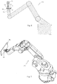
- the next process step which is depicted in Figures 5 and 6 can then be carried out at the assembly site.
- Reference number 32 generally denotes an automatic handling machine or robot known per se.
- the robot 32 has a gripping device 34 at the end of its manipulating arm, at which the fastening element 10 with its fastening section 18 is held such that the contact surface 14 is upward facing.
- the robot 32 has taken up the fastening element 10 from a storage place beforehand. In the position shown in Figures 5 and 6 , the robot 32 holds the fastening element 10 beneath a further glue application device 36.
- a permanent glue 38 for permanently holding the fastening element 10 is applied to the carrier component on the second area of the contact surface 14 formed by the circular deepening 22, likewise in a fluid state. Due to the deepening 22 and the ring-shaped delimitation produced by the already hardened contact glue 26, the permanent glue 38, which is still fluid at this point, is held reliably delimited in the second area.
- the further process step depicted in Figures 7 and 8 can be carried out subsequently.
- the robot 32 places the fastening element 10 with its contact surface 14 on the surface of a carrier component 40 and presses said fastening element using a defined compressive force onto the surface of the carrier component 40.
- the already hardened contact glue 26 thereby indirectly creates an adhesive action, so that the fastening element 10 is held on the carrier component 40 by the contact glue 26.
- the gripping device 34 of the robot 32 can therefore by released from the fastening element 10 and the robot 32 can take up a further fastening element 10 to carry out the process steps shown in Figures 5 to 8 .
- the permanent glue 38 can then harden without further holding measures, of a mechanical nature for example, being necessary. As the hardening increases, the permanent glue also helps to hold the fastening element 10 on the carrier component 40. When the permanent glue 38 is completely hardened, it transmits a significantly greater holding action than the contact glue 26.
- the carrier component 40 may be a bodywork part of an automobile, for example.
- a plurality of fixing elements 10 according to the invention is secured to the carrier component 40 in the manner described above.
- a component to be fastened to the carrier component 40 for example an internal lining or protective part, can be fastened to the fastening elements 10 and therefore to the carrier component 40 subsequently.
- this component exhibits fastening sections corresponding to the fastening sections 18 of the fastening elements 10, said fastening sections being capable of being used for fastening to the fastening sections 18 by means of a snap-on connection, for example.
- the assembly of the fastening element 10 according to the invention is therefore significantly simplified. At the same time, very high holding forces are achieved by the permanent glue 38 during operation.
- Fig. 9 shows a second exemplary embodiment of a fastening element 10' according to the invention.
- This fastening element 10' largely corresponds in terms of its design and function and therefore in relation to the process steps explained above to the fastening element 10 according to the first exemplary embodiment shown in Fig. 1 .
- the fastening element 10' from Fig. 9 as a fastening section exhibits no fastening balls 18, however, but a fastening bolt 18' with an outer thread, which extends coaxially to the disk-shaped basic body 12 starting from the underside 16 of the disk-shaped basic body 12 opposite the contact surface 14.
- a component to be fastened to the carrier component 40 may in turn be fastened to the fastening sections corresponding to the fastening sections 18'.
- the outer thread of the threaded bolt 18' permits non-destructive dismantling in a simple manner.
Landscapes
- Engineering & Computer Science (AREA)
- General Engineering & Computer Science (AREA)
- Mechanical Engineering (AREA)
- Chemical & Material Sciences (AREA)
- Organic Chemistry (AREA)
- Connection Of Plates (AREA)
- Adhesives Or Adhesive Processes (AREA)
Claims (11)
- Procédé de collage d'un élément de fixation (10, 10') sur un composant porteur (40) d'une automobile, dans lequel l'élément de fixation (10, 10') comprend une surface de contact (14) pour le collage sur le composant porteur (40) et au moins une section de fixation (18, 18') à l'opposé de la surface de contact (14), dans lequel on peut fixer sur la section de fixation un composant à fixer sur le composant porteur (40), comprenant les étapes suivantes :- on applique, pour un maintien préliminaire de l'élément de fixation (10, 10') sur le composant porteur (40), un adhésif de contact (26) à une première zone (20) de la surface de contact (14),- on applique, pour un maintien permanent de l'élément de fixation (10, 10') sur le composant porteur (40), un adhésif permanent (38) à une seconde zone (22) différente de la surface de contact (14),- suite à l'application de l'adhésif de contact (26) et de l'adhésif permanent (38) à la surface de contact, on place l'élément de fixation (10, 10') avec sa surface de contact (14) sur le composant porteur (40), moyennant quoi l'adhésif de contact (26) assure un maintien préliminaire de l'élément de fixation (10, 10') sur le composant porteur (40) jusqu'à ce que l'adhésif permanent (38) durcisse et ainsi maintienne de façon permanente l'élément de fixation (10, 10') sur le composant porteur (40), dans lequel l'adhésif de contact reste sur l'élément de fixation (10, 10').
- Procédé selon la revendication 1, caractérisé en ce que l'adhésif de contact (26) est appliqué à la surface de contact (14) à l'état fluide et est réticulé avant l'application de l'adhésif permanent (38) sur la surface de contact (14).
- Procédé selon la revendication 2, caractérisé en ce que le durcissement s'effectue par rayonnement, en particulier par rayonnement ultraviolet.
- Procédé selon l'une quelconque des revendications précédentes, caractérisé en ce que l'adhésif permanent (38) est appliqué à la surface de contact (14) à l'état fluide.
- Procédé selon l'une quelconque des revendications précédentes, caractérisé en ce que l'adhésif permanent durcit automatiquement.
- Procédé selon l'une quelconque des revendications précédentes, caractérisé en ce que on applique l'adhésif de contact (26) à la surface de contact (14) dans une zone périphérique (20) et on applique l'adhésif permanent (38) à la surface de contact (14) dans une zone (22) entourée par la zone périphérique (20).
- Procédé selon l'une quelconque des revendications précédentes, caractérisé en ce que la première zone (20) et/ou la seconde zone (22) de la surface de contact (14) sont formées par un approfondissement (20, 22).
- Procédé selon l'une quelconque des revendications précédentes, caractérisé en ce que l'élément de fixation (10, 10') est placé sur le composant porteur (40) par un robot.
- Procédé selon l'une quelconque des revendications précédentes, caractérisé en ce que pendant le durcissement de l'adhésif permanent (38) l'élément de fixation (10, 10') n'est maintenu sur le composant porteur (40) que par l'effet collant de l'adhésif de contact (26) et l'effet collant de l'adhésif permanent (38) au fur et à mesure qu'il augmente avec son durcissement.
- Procédé selon l'une quelconque des revendications précédentes, caractérisé en ce que l'application et éventuellement le durcissement de l'adhésif de contact (26) s'effectue au lieu de fabrication de l'élément de fixation (10, 10'), et en ce que l'application de l'adhésif permanent (38) et le collage de l'élément de fixation (10, 10') sur le composant porteur (40) s'effectue au lieu d'assemblage, différent du lieu de fabrication.
- Procédé selon l'une quelconque des revendications précédentes, caractérisé en ce que la section de fixation (18, 18') est constituée par une boule de fixation (18) ou un boulon de fixation (18').
Applications Claiming Priority (2)
| Application Number | Priority Date | Filing Date | Title |
|---|---|---|---|
| DE102012000353A DE102012000353A1 (de) | 2012-01-11 | 2012-01-11 | Verfahren zum Aufkleben eines Befestigungselements auf ein Trägerbauteil eines Automobils und Befestigungselement |
| PCT/US2013/020722 WO2013106362A1 (fr) | 2012-01-11 | 2013-01-09 | Procédé de collage d'un élément de fixation sur un élément de support d'un véhicule automobile et élément de fixation |
Publications (2)
| Publication Number | Publication Date |
|---|---|
| EP2802785A1 EP2802785A1 (fr) | 2014-11-19 |
| EP2802785B1 true EP2802785B1 (fr) | 2017-06-28 |
Family
ID=47595086
Family Applications (1)
| Application Number | Title | Priority Date | Filing Date |
|---|---|---|---|
| EP13700817.3A Not-in-force EP2802785B1 (fr) | 2012-01-11 | 2013-01-09 | Procédé de collage d'un élément de fixation sur un élément de support d'un véhicule automobile |
Country Status (4)
| Country | Link |
|---|---|
| US (1) | US20140374001A1 (fr) |
| EP (1) | EP2802785B1 (fr) |
| DE (1) | DE102012000353A1 (fr) |
| WO (1) | WO2013106362A1 (fr) |
Families Citing this family (7)
| Publication number | Priority date | Publication date | Assignee | Title |
|---|---|---|---|---|
| US9885217B2 (en) | 2014-08-21 | 2018-02-06 | Baker Hughes, A Ge Company, Llc | Non-marring shifting tool collet |
| CN106594022B (zh) * | 2016-03-22 | 2019-05-14 | 北京卫星环境工程研究所 | 用于安装航天器复杂曲面加热器的加压装置 |
| EP3330548B1 (fr) * | 2016-11-30 | 2021-01-20 | Newfrey LLC | Élément de fixation et son procédé de fabrication |
| DE102016125660A1 (de) * | 2016-12-23 | 2018-06-28 | Böllhoff Verbindungstechnik GmbH | Befestigungseinleger für ein Bauteil aus Kunststoff-, Schaum- oder Verbundmaterial |
| EP4001673A1 (fr) * | 2020-11-17 | 2022-05-25 | Newfrey LLC | Procédé d'assemblage d'un élément de fixation à une pièce à usiner |
| EP4502403A1 (fr) | 2023-08-02 | 2025-02-05 | Newfrey LLC | Élément de fixation avec adhésif et ses procédés d'utilisation et de fabrication |
| EP4582706A1 (fr) | 2024-01-05 | 2025-07-09 | Newfrey LLC | Élément de fixation avec cire de fixation et procédé de fixation dudit élément de fixation à une pièce |
Family Cites Families (9)
| Publication number | Priority date | Publication date | Assignee | Title |
|---|---|---|---|---|
| US4390576A (en) * | 1980-09-19 | 1983-06-28 | Physical Systems, Inc. | Adhesive attachment assembly |
| JPS6065082A (ja) * | 1983-09-21 | 1985-04-13 | Nifco Inc | スタツドのワ−クに対する固定方法 |
| US4822224A (en) * | 1987-11-05 | 1989-04-18 | Chrysler Motors Corporation | Harness retainer stud |
| DE4038989A1 (de) * | 1990-12-06 | 1992-06-11 | Siemens Ag | Verfahren zur spannungsarmen verklebung |
| US5277530A (en) * | 1992-11-06 | 1994-01-11 | Theodore Sweeney & Co., Inc. | Adhesively secured pump fastener system |
| US5593120A (en) * | 1994-11-21 | 1997-01-14 | Minnesota Mining And Manufacturing Company | Quick-mounting fastening assembly |
| DE19941996A1 (de) * | 1999-09-02 | 2001-03-08 | Sca Schucker Gmbh | Verfahren und Anordnung zum Aufheizen eines Bauteils entlang einer vorgegebenen Bahn |
| US20090057510A1 (en) * | 2007-08-28 | 2009-03-05 | John Orban | Suction cup |
| DE102008058389A1 (de) * | 2008-11-21 | 2010-05-27 | Sfs Intec Holding Ag | Punktbefestiger, Klebeverbindung und Verfahren zum Herstellen einer Klebeverbindung |
-
2012
- 2012-01-11 DE DE102012000353A patent/DE102012000353A1/de not_active Withdrawn
-
2013
- 2013-01-09 US US14/370,527 patent/US20140374001A1/en not_active Abandoned
- 2013-01-09 EP EP13700817.3A patent/EP2802785B1/fr not_active Not-in-force
- 2013-01-09 WO PCT/US2013/020722 patent/WO2013106362A1/fr not_active Ceased
Non-Patent Citations (1)
| Title |
|---|
| None * |
Also Published As
| Publication number | Publication date |
|---|---|
| EP2802785A1 (fr) | 2014-11-19 |
| DE102012000353A1 (de) | 2013-07-11 |
| US20140374001A1 (en) | 2014-12-25 |
| WO2013106362A1 (fr) | 2013-07-18 |
Similar Documents
| Publication | Publication Date | Title |
|---|---|---|
| EP2802785B1 (fr) | Procédé de collage d'un élément de fixation sur un élément de support d'un véhicule automobile | |
| US10173370B2 (en) | Joining method | |
| US7442581B2 (en) | Flexible carrier and release method for high volume electronic package fabrication | |
| US8888426B2 (en) | Functional element for attachment to a plastic component and a component assembly | |
| EP2365559A3 (fr) | Durcissement sélectif d'adhésif dans des assemblages modulaires | |
| US20100206418A1 (en) | Method for connecting pipes and pipe having a profiled face end | |
| ATE318277T1 (de) | Lösemittelhaltiges, thermisch und mit aktinischer strahlung härtbares mehrkomponentensystem und seine verwendung | |
| EP2911862B1 (fr) | Composant d'assemblage composite et procédé de production correspondant | |
| US20150330424A1 (en) | Frictionally engaged fastening of a first component to a second component | |
| JP2009073088A (ja) | インサート成形体およびインサート成形体の製造方法 | |
| WO2008149804A1 (fr) | Procédé et dispositif de fabrication de panneau d'étanchéité et dispositif de fabrication d'un panneau d'affichage plasma | |
| EP4248098B1 (fr) | Procédé d'assemblage d'un élément de fixation à une pièce à usiner | |
| CN103016475B (zh) | 用于将第一部件连接到第二部件的方法 | |
| KR101258406B1 (ko) | 스티커형 구조물 접착 패드 | |
| EP4582706A1 (fr) | Élément de fixation avec cire de fixation et procédé de fixation dudit élément de fixation à une pièce | |
| JP6287224B2 (ja) | 車体パネル構造 | |
| JP6791923B2 (ja) | 加工システムおよび加工方法 | |
| JP6328670B2 (ja) | 円筒形接着対象物の内外面にゴム層を接着するための前処理方法 | |
| WO2025027045A1 (fr) | Élément de fixation avec adhésif et ses procédés d'utilisation et de fabrication | |
| JP5432701B2 (ja) | 二液型接着剤用接着装置、及び該装置を用いた物品の接着方法 | |
| CN103003044A (zh) | 用于制造摩擦衬片的方法 | |
| JPWO2018100721A1 (ja) | パネル加工方法、パネルおよびパネル加工装置 | |
| JPH0745298Y2 (ja) | 複合型光学素子の離型装置 | |
| JP2003147284A (ja) | 接着剤による接着方法 | |
| JPH01158684A (ja) | 磁気ディスクの組立方法 |
Legal Events
| Date | Code | Title | Description |
|---|---|---|---|
| PUAI | Public reference made under article 153(3) epc to a published international application that has entered the european phase |
Free format text: ORIGINAL CODE: 0009012 |
|
| 17P | Request for examination filed |
Effective date: 20140422 |
|
| AK | Designated contracting states |
Kind code of ref document: A1 Designated state(s): AL AT BE BG CH CY CZ DE DK EE ES FI FR GB GR HR HU IE IS IT LI LT LU LV MC MK MT NL NO PL PT RO RS SE SI SK SM TR |
|
| DAX | Request for extension of the european patent (deleted) | ||
| REG | Reference to a national code |
Ref country code: DE Ref legal event code: R079 Ref document number: 602013022805 Country of ref document: DE Free format text: PREVIOUS MAIN CLASS: F16B0011000000 Ipc: F16B0005000000 |
|
| GRAP | Despatch of communication of intention to grant a patent |
Free format text: ORIGINAL CODE: EPIDOSNIGR1 |
|
| STAA | Information on the status of an ep patent application or granted ep patent |
Free format text: STATUS: GRANT OF PATENT IS INTENDED |
|
| RIC1 | Information provided on ipc code assigned before grant |
Ipc: F16B 11/00 20060101ALI20170116BHEP Ipc: F16B 5/00 20060101AFI20170116BHEP |
|
| INTG | Intention to grant announced |
Effective date: 20170220 |
|
| GRAS | Grant fee paid |
Free format text: ORIGINAL CODE: EPIDOSNIGR3 |
|
| GRAA | (expected) grant |
Free format text: ORIGINAL CODE: 0009210 |
|
| STAA | Information on the status of an ep patent application or granted ep patent |
Free format text: STATUS: THE PATENT HAS BEEN GRANTED |
|
| AK | Designated contracting states |
Kind code of ref document: B1 Designated state(s): AL AT BE BG CH CY CZ DE DK EE ES FI FR GB GR HR HU IE IS IT LI LT LU LV MC MK MT NL NO PL PT RO RS SE SI SK SM TR |
|
| REG | Reference to a national code |
Ref country code: GB Ref legal event code: FG4D |
|
| REG | Reference to a national code |
Ref country code: CH Ref legal event code: EP |
|
| REG | Reference to a national code |
Ref country code: AT Ref legal event code: REF Ref document number: 905123 Country of ref document: AT Kind code of ref document: T Effective date: 20170715 |
|
| REG | Reference to a national code |
Ref country code: IE Ref legal event code: FG4D |
|
| REG | Reference to a national code |
Ref country code: DE Ref legal event code: R096 Ref document number: 602013022805 Country of ref document: DE |
|
| PG25 | Lapsed in a contracting state [announced via postgrant information from national office to epo] |
Ref country code: GR Free format text: LAPSE BECAUSE OF FAILURE TO SUBMIT A TRANSLATION OF THE DESCRIPTION OR TO PAY THE FEE WITHIN THE PRESCRIBED TIME-LIMIT Effective date: 20170929 Ref country code: LT Free format text: LAPSE BECAUSE OF FAILURE TO SUBMIT A TRANSLATION OF THE DESCRIPTION OR TO PAY THE FEE WITHIN THE PRESCRIBED TIME-LIMIT Effective date: 20170628 Ref country code: HR Free format text: LAPSE BECAUSE OF FAILURE TO SUBMIT A TRANSLATION OF THE DESCRIPTION OR TO PAY THE FEE WITHIN THE PRESCRIBED TIME-LIMIT Effective date: 20170628 Ref country code: FI Free format text: LAPSE BECAUSE OF FAILURE TO SUBMIT A TRANSLATION OF THE DESCRIPTION OR TO PAY THE FEE WITHIN THE PRESCRIBED TIME-LIMIT Effective date: 20170628 Ref country code: NO Free format text: LAPSE BECAUSE OF FAILURE TO SUBMIT A TRANSLATION OF THE DESCRIPTION OR TO PAY THE FEE WITHIN THE PRESCRIBED TIME-LIMIT Effective date: 20170928 |
|
| REG | Reference to a national code |
Ref country code: NL Ref legal event code: MP Effective date: 20170628 |
|
| REG | Reference to a national code |
Ref country code: LT Ref legal event code: MG4D |
|
| REG | Reference to a national code |
Ref country code: AT Ref legal event code: MK05 Ref document number: 905123 Country of ref document: AT Kind code of ref document: T Effective date: 20170628 |
|
| PG25 | Lapsed in a contracting state [announced via postgrant information from national office to epo] |
Ref country code: LV Free format text: LAPSE BECAUSE OF FAILURE TO SUBMIT A TRANSLATION OF THE DESCRIPTION OR TO PAY THE FEE WITHIN THE PRESCRIBED TIME-LIMIT Effective date: 20170628 Ref country code: BG Free format text: LAPSE BECAUSE OF FAILURE TO SUBMIT A TRANSLATION OF THE DESCRIPTION OR TO PAY THE FEE WITHIN THE PRESCRIBED TIME-LIMIT Effective date: 20170928 Ref country code: NL Free format text: LAPSE BECAUSE OF FAILURE TO SUBMIT A TRANSLATION OF THE DESCRIPTION OR TO PAY THE FEE WITHIN THE PRESCRIBED TIME-LIMIT Effective date: 20170628 Ref country code: SE Free format text: LAPSE BECAUSE OF FAILURE TO SUBMIT A TRANSLATION OF THE DESCRIPTION OR TO PAY THE FEE WITHIN THE PRESCRIBED TIME-LIMIT Effective date: 20170628 Ref country code: RS Free format text: LAPSE BECAUSE OF FAILURE TO SUBMIT A TRANSLATION OF THE DESCRIPTION OR TO PAY THE FEE WITHIN THE PRESCRIBED TIME-LIMIT Effective date: 20170628 |
|
| REG | Reference to a national code |
Ref country code: FR Ref legal event code: PLFP Year of fee payment: 6 |
|
| PG25 | Lapsed in a contracting state [announced via postgrant information from national office to epo] |
Ref country code: CZ Free format text: LAPSE BECAUSE OF FAILURE TO SUBMIT A TRANSLATION OF THE DESCRIPTION OR TO PAY THE FEE WITHIN THE PRESCRIBED TIME-LIMIT Effective date: 20170628 Ref country code: SK Free format text: LAPSE BECAUSE OF FAILURE TO SUBMIT A TRANSLATION OF THE DESCRIPTION OR TO PAY THE FEE WITHIN THE PRESCRIBED TIME-LIMIT Effective date: 20170628 Ref country code: AT Free format text: LAPSE BECAUSE OF FAILURE TO SUBMIT A TRANSLATION OF THE DESCRIPTION OR TO PAY THE FEE WITHIN THE PRESCRIBED TIME-LIMIT Effective date: 20170628 Ref country code: RO Free format text: LAPSE BECAUSE OF FAILURE TO SUBMIT A TRANSLATION OF THE DESCRIPTION OR TO PAY THE FEE WITHIN THE PRESCRIBED TIME-LIMIT Effective date: 20170628 Ref country code: EE Free format text: LAPSE BECAUSE OF FAILURE TO SUBMIT A TRANSLATION OF THE DESCRIPTION OR TO PAY THE FEE WITHIN THE PRESCRIBED TIME-LIMIT Effective date: 20170628 |
|
| PG25 | Lapsed in a contracting state [announced via postgrant information from national office to epo] |
Ref country code: IS Free format text: LAPSE BECAUSE OF FAILURE TO SUBMIT A TRANSLATION OF THE DESCRIPTION OR TO PAY THE FEE WITHIN THE PRESCRIBED TIME-LIMIT Effective date: 20171028 Ref country code: SM Free format text: LAPSE BECAUSE OF FAILURE TO SUBMIT A TRANSLATION OF THE DESCRIPTION OR TO PAY THE FEE WITHIN THE PRESCRIBED TIME-LIMIT Effective date: 20170628 Ref country code: IT Free format text: LAPSE BECAUSE OF FAILURE TO SUBMIT A TRANSLATION OF THE DESCRIPTION OR TO PAY THE FEE WITHIN THE PRESCRIBED TIME-LIMIT Effective date: 20170628 Ref country code: PL Free format text: LAPSE BECAUSE OF FAILURE TO SUBMIT A TRANSLATION OF THE DESCRIPTION OR TO PAY THE FEE WITHIN THE PRESCRIBED TIME-LIMIT Effective date: 20170628 Ref country code: ES Free format text: LAPSE BECAUSE OF FAILURE TO SUBMIT A TRANSLATION OF THE DESCRIPTION OR TO PAY THE FEE WITHIN THE PRESCRIBED TIME-LIMIT Effective date: 20170628 |
|
| REG | Reference to a national code |
Ref country code: DE Ref legal event code: R097 Ref document number: 602013022805 Country of ref document: DE |
|
| PG25 | Lapsed in a contracting state [announced via postgrant information from national office to epo] |
Ref country code: DK Free format text: LAPSE BECAUSE OF FAILURE TO SUBMIT A TRANSLATION OF THE DESCRIPTION OR TO PAY THE FEE WITHIN THE PRESCRIBED TIME-LIMIT Effective date: 20170628 |
|
| PGFP | Annual fee paid to national office [announced via postgrant information from national office to epo] |
Ref country code: DE Payment date: 20180129 Year of fee payment: 6 |
|
| PLBE | No opposition filed within time limit |
Free format text: ORIGINAL CODE: 0009261 |
|
| PGFP | Annual fee paid to national office [announced via postgrant information from national office to epo] |
Ref country code: FR Payment date: 20180125 Year of fee payment: 6 |
|
| 26N | No opposition filed |
Effective date: 20180329 |
|
| PG25 | Lapsed in a contracting state [announced via postgrant information from national office to epo] |
Ref country code: SI Free format text: LAPSE BECAUSE OF FAILURE TO SUBMIT A TRANSLATION OF THE DESCRIPTION OR TO PAY THE FEE WITHIN THE PRESCRIBED TIME-LIMIT Effective date: 20170628 |
|
| REG | Reference to a national code |
Ref country code: CH Ref legal event code: PL |
|
| GBPC | Gb: european patent ceased through non-payment of renewal fee |
Effective date: 20180109 |
|
| PG25 | Lapsed in a contracting state [announced via postgrant information from national office to epo] |
Ref country code: LU Free format text: LAPSE BECAUSE OF NON-PAYMENT OF DUE FEES Effective date: 20180109 |
|
| REG | Reference to a national code |
Ref country code: IE Ref legal event code: MM4A |
|
| REG | Reference to a national code |
Ref country code: BE Ref legal event code: MM Effective date: 20180131 |
|
| PG25 | Lapsed in a contracting state [announced via postgrant information from national office to epo] |
Ref country code: GB Free format text: LAPSE BECAUSE OF NON-PAYMENT OF DUE FEES Effective date: 20180109 Ref country code: CH Free format text: LAPSE BECAUSE OF NON-PAYMENT OF DUE FEES Effective date: 20180131 Ref country code: BE Free format text: LAPSE BECAUSE OF NON-PAYMENT OF DUE FEES Effective date: 20180131 Ref country code: LI Free format text: LAPSE BECAUSE OF NON-PAYMENT OF DUE FEES Effective date: 20180131 |
|
| PG25 | Lapsed in a contracting state [announced via postgrant information from national office to epo] |
Ref country code: IE Free format text: LAPSE BECAUSE OF NON-PAYMENT OF DUE FEES Effective date: 20180109 |
|
| PG25 | Lapsed in a contracting state [announced via postgrant information from national office to epo] |
Ref country code: MC Free format text: LAPSE BECAUSE OF FAILURE TO SUBMIT A TRANSLATION OF THE DESCRIPTION OR TO PAY THE FEE WITHIN THE PRESCRIBED TIME-LIMIT Effective date: 20170628 |
|
| REG | Reference to a national code |
Ref country code: DE Ref legal event code: R119 Ref document number: 602013022805 Country of ref document: DE |
|
| PG25 | Lapsed in a contracting state [announced via postgrant information from national office to epo] |
Ref country code: FR Free format text: LAPSE BECAUSE OF NON-PAYMENT OF DUE FEES Effective date: 20190131 Ref country code: DE Free format text: LAPSE BECAUSE OF NON-PAYMENT OF DUE FEES Effective date: 20190801 |
|
| PG25 | Lapsed in a contracting state [announced via postgrant information from national office to epo] |
Ref country code: MT Free format text: LAPSE BECAUSE OF NON-PAYMENT OF DUE FEES Effective date: 20180109 |
|
| PG25 | Lapsed in a contracting state [announced via postgrant information from national office to epo] |
Ref country code: TR Free format text: LAPSE BECAUSE OF FAILURE TO SUBMIT A TRANSLATION OF THE DESCRIPTION OR TO PAY THE FEE WITHIN THE PRESCRIBED TIME-LIMIT Effective date: 20170628 |
|
| PG25 | Lapsed in a contracting state [announced via postgrant information from national office to epo] |
Ref country code: PT Free format text: LAPSE BECAUSE OF FAILURE TO SUBMIT A TRANSLATION OF THE DESCRIPTION OR TO PAY THE FEE WITHIN THE PRESCRIBED TIME-LIMIT Effective date: 20170628 Ref country code: HU Free format text: LAPSE BECAUSE OF FAILURE TO SUBMIT A TRANSLATION OF THE DESCRIPTION OR TO PAY THE FEE WITHIN THE PRESCRIBED TIME-LIMIT; INVALID AB INITIO Effective date: 20130109 |
|
| PG25 | Lapsed in a contracting state [announced via postgrant information from national office to epo] |
Ref country code: MK Free format text: LAPSE BECAUSE OF NON-PAYMENT OF DUE FEES Effective date: 20170628 Ref country code: CY Free format text: LAPSE BECAUSE OF FAILURE TO SUBMIT A TRANSLATION OF THE DESCRIPTION OR TO PAY THE FEE WITHIN THE PRESCRIBED TIME-LIMIT Effective date: 20170628 |
|
| PG25 | Lapsed in a contracting state [announced via postgrant information from national office to epo] |
Ref country code: AL Free format text: LAPSE BECAUSE OF FAILURE TO SUBMIT A TRANSLATION OF THE DESCRIPTION OR TO PAY THE FEE WITHIN THE PRESCRIBED TIME-LIMIT Effective date: 20170628 |
|
| STAA | Information on the status of an ep patent application or granted ep patent |
Free format text: STATUS: NO OPPOSITION FILED WITHIN TIME LIMIT |