EP2802807B1 - Projecteur de véhicule du type laser - Google Patents
Projecteur de véhicule du type laser Download PDFInfo
- Publication number
- EP2802807B1 EP2802807B1 EP13714181.8A EP13714181A EP2802807B1 EP 2802807 B1 EP2802807 B1 EP 2802807B1 EP 13714181 A EP13714181 A EP 13714181A EP 2802807 B1 EP2802807 B1 EP 2802807B1
- Authority
- EP
- European Patent Office
- Prior art keywords
- light
- vehicle headlight
- guiding element
- light source
- laser
- Prior art date
- Legal status (The legal status is an assumption and is not a legal conclusion. Google has not performed a legal analysis and makes no representation as to the accuracy of the status listed.)
- Active
Links
Images
Classifications
-
- F—MECHANICAL ENGINEERING; LIGHTING; HEATING; WEAPONS; BLASTING
- F21—LIGHTING
- F21S—NON-PORTABLE LIGHTING DEVICES; SYSTEMS THEREOF; VEHICLE LIGHTING DEVICES SPECIALLY ADAPTED FOR VEHICLE EXTERIORS
- F21S41/00—Illuminating devices specially adapted for vehicle exteriors, e.g. headlamps
- F21S41/10—Illuminating devices specially adapted for vehicle exteriors, e.g. headlamps characterised by the light source
- F21S41/14—Illuminating devices specially adapted for vehicle exteriors, e.g. headlamps characterised by the light source characterised by the type of light source
- F21S41/16—Laser light sources
-
- F—MECHANICAL ENGINEERING; LIGHTING; HEATING; WEAPONS; BLASTING
- F21—LIGHTING
- F21S—NON-PORTABLE LIGHTING DEVICES; SYSTEMS THEREOF; VEHICLE LIGHTING DEVICES SPECIALLY ADAPTED FOR VEHICLE EXTERIORS
- F21S41/00—Illuminating devices specially adapted for vehicle exteriors, e.g. headlamps
- F21S41/30—Illuminating devices specially adapted for vehicle exteriors, e.g. headlamps characterised by reflectors
- F21S41/37—Illuminating devices specially adapted for vehicle exteriors, e.g. headlamps characterised by reflectors characterised by their material, surface treatment or coatings
-
- F—MECHANICAL ENGINEERING; LIGHTING; HEATING; WEAPONS; BLASTING
- F21—LIGHTING
- F21S—NON-PORTABLE LIGHTING DEVICES; SYSTEMS THEREOF; VEHICLE LIGHTING DEVICES SPECIALLY ADAPTED FOR VEHICLE EXTERIORS
- F21S41/00—Illuminating devices specially adapted for vehicle exteriors, e.g. headlamps
- F21S41/10—Illuminating devices specially adapted for vehicle exteriors, e.g. headlamps characterised by the light source
- F21S41/14—Illuminating devices specially adapted for vehicle exteriors, e.g. headlamps characterised by the light source characterised by the type of light source
- F21S41/176—Light sources where the light is generated by photoluminescent material spaced from a primary light generating element
-
- F—MECHANICAL ENGINEERING; LIGHTING; HEATING; WEAPONS; BLASTING
- F21—LIGHTING
- F21S—NON-PORTABLE LIGHTING DEVICES; SYSTEMS THEREOF; VEHICLE LIGHTING DEVICES SPECIALLY ADAPTED FOR VEHICLE EXTERIORS
- F21S41/00—Illuminating devices specially adapted for vehicle exteriors, e.g. headlamps
- F21S41/20—Illuminating devices specially adapted for vehicle exteriors, e.g. headlamps characterised by refractors, transparent cover plates, light guides or filters
- F21S41/24—Light guides
-
- F—MECHANICAL ENGINEERING; LIGHTING; HEATING; WEAPONS; BLASTING
- F21—LIGHTING
- F21S—NON-PORTABLE LIGHTING DEVICES; SYSTEMS THEREOF; VEHICLE LIGHTING DEVICES SPECIALLY ADAPTED FOR VEHICLE EXTERIORS
- F21S41/00—Illuminating devices specially adapted for vehicle exteriors, e.g. headlamps
- F21S41/20—Illuminating devices specially adapted for vehicle exteriors, e.g. headlamps characterised by refractors, transparent cover plates, light guides or filters
- F21S41/285—Refractors, transparent cover plates, light guides or filters not provided in groups F21S41/24 - F21S41/2805
-
- F—MECHANICAL ENGINEERING; LIGHTING; HEATING; WEAPONS; BLASTING
- F21—LIGHTING
- F21S—NON-PORTABLE LIGHTING DEVICES; SYSTEMS THEREOF; VEHICLE LIGHTING DEVICES SPECIALLY ADAPTED FOR VEHICLE EXTERIORS
- F21S41/00—Illuminating devices specially adapted for vehicle exteriors, e.g. headlamps
- F21S41/20—Illuminating devices specially adapted for vehicle exteriors, e.g. headlamps characterised by refractors, transparent cover plates, light guides or filters
- F21S41/29—Attachment thereof
-
- F—MECHANICAL ENGINEERING; LIGHTING; HEATING; WEAPONS; BLASTING
- F21—LIGHTING
- F21S—NON-PORTABLE LIGHTING DEVICES; SYSTEMS THEREOF; VEHICLE LIGHTING DEVICES SPECIALLY ADAPTED FOR VEHICLE EXTERIORS
- F21S41/00—Illuminating devices specially adapted for vehicle exteriors, e.g. headlamps
- F21S41/30—Illuminating devices specially adapted for vehicle exteriors, e.g. headlamps characterised by reflectors
- F21S41/32—Optical layout thereof
- F21S41/36—Combinations of two or more separate reflectors
- F21S41/365—Combinations of two or more separate reflectors successively reflecting the light
-
- F—MECHANICAL ENGINEERING; LIGHTING; HEATING; WEAPONS; BLASTING
- F21—LIGHTING
- F21S—NON-PORTABLE LIGHTING DEVICES; SYSTEMS THEREOF; VEHICLE LIGHTING DEVICES SPECIALLY ADAPTED FOR VEHICLE EXTERIORS
- F21S41/00—Illuminating devices specially adapted for vehicle exteriors, e.g. headlamps
- F21S41/40—Illuminating devices specially adapted for vehicle exteriors, e.g. headlamps characterised by screens, non-reflecting members, light-shielding members or fixed shades
-
- F—MECHANICAL ENGINEERING; LIGHTING; HEATING; WEAPONS; BLASTING
- F21—LIGHTING
- F21S—NON-PORTABLE LIGHTING DEVICES; SYSTEMS THEREOF; VEHICLE LIGHTING DEVICES SPECIALLY ADAPTED FOR VEHICLE EXTERIORS
- F21S45/00—Arrangements within vehicle lighting devices specially adapted for vehicle exteriors, for purposes other than emission or distribution of light
- F21S45/40—Cooling of lighting devices
- F21S45/42—Forced cooling
- F21S45/43—Forced cooling using gas
-
- F—MECHANICAL ENGINEERING; LIGHTING; HEATING; WEAPONS; BLASTING
- F21—LIGHTING
- F21S—NON-PORTABLE LIGHTING DEVICES; SYSTEMS THEREOF; VEHICLE LIGHTING DEVICES SPECIALLY ADAPTED FOR VEHICLE EXTERIORS
- F21S45/00—Arrangements within vehicle lighting devices specially adapted for vehicle exteriors, for purposes other than emission or distribution of light
- F21S45/60—Heating of lighting devices, e.g. for demisting
Definitions
- the invention relates to a laser vehicle headlamp comprising at least one light-guiding element, at least one laser light source and at least one light element that can be irradiated by the laser light source and thus excited to emit visible light.
- Various types of vehicle headlights are known in the prior art, with headlamps with discharge lamps and halogen light sources being used in recent years predominantly.
- laser light sources such as semiconductor lasers is being increasingly tested, since they are advantageous in this regard.
- a light source e.g. a phosphorus compound, a YAG crystal with cerium doping, etc.
- a so-called phosphor converter eg a phosphorus compound, a YAG crystal with cerium doping, etc.
- the phosphor converter thus converts laser light into light of other wavelengths.
- the laser light source is arranged at a distance from the luminous element and the laser light travels a free path before impinging on the luminous element.
- the laser light it is necessary that the laser light impinges exactly on the luminous element - on the one hand, in order to exploit the radiated power as well as possible, on the other hand for safety reasons.
- the laser light sources used emit powers of currently up to 3 W and more, in the case of a malfunction (for example, if the light element is not optimally hit) may result from high-intensity eye-damaging laser light radiation to injuries, but in any case to endanger other road users.
- US 2011/0249460 A is a generic laser vehicle headlights known. It is therefore an object of the invention to provide a solution for laser vehicle headlights which overcomes the above-mentioned problems of the prior art.
- the light guide a first side, which is at least partially formed as a light entrance surface, and one of the first side opposite arranged second side, which is at least partially formed as a light exit surface and the at least one Receiving for the at least one luminous element is assigned, wherein the light entrance surface is associated with at least one oriented in the direction of the interior of the Lichtleitelements, light from the light entrance surface in the direction of the recording for the luminous element reflecting the first reflection region, and wherein the light exit surface at least one in the direction of Interior of the light guide oriented, light from the light emitting element in the direction of the light exit surface reflective second reflection region is associated.
- the invention makes it possible to compensate for positioning errors of the light-conducting element or of the luminous element arranged therein with respect to the laser light source, since, due to the first reflection region, also light which does not strike the luminous element precisely is deflected onto the luminous element.
- a complete exploitation of the light emitted by the luminous element is made possible because the second reflection region deflects light emitted by the luminous element towards the light exit surface - this light component would otherwise not be usable.
- the reflective property of the reflection ranges arises, inter alia, due to the total reflection at the interface light guide element environment.
- both the high demands on the mounting of the luminous element relative to the laser light source can be reduced and thus fulfilled (for example, also during shaking during operation by vibration load, resonances, thermal expansion, etc.) and a greater luminous efficacy can be ensured.
- the light-guiding element preferably consists of a transparent material such as glass or plastic - the light-guiding element is embodied, for example, in one piece as a volumetric body, that is to say it consists of a material throughout. But it can also be designed as a hollow body.
- the second reflection region is predominantly on the side of the light-guiding element facing the laser light source in the mounted state of the light-guiding element arranged.
- light which is emitted by the luminous element in the direction of the light entry surface can thus be deflected in the direction of the light exit surface and thereby made usable.
- “predominantly” is to be understood here that more than half of the second reflection region is arranged on the side of the light-guiding element facing the laser light source in the mounted state of the light-guiding element.
- the reflection areas can in principle be arbitrary.
- the first reflection region can be configured in such a way that incident light is deflected by means of total reflection.
- the reflection regions are each formed as at least one reflection layer applied on the outside of the light-guiding element, which is preferably covered with an absorption layer.
- correspondingly reflective or absorbing layers can be applied by vapor deposition, painting or else by the mechanical fastening (for example gluing) of corresponding cover parts.
- the light-guiding element is designed as a free-form surface in the region of the first and / or the second reflection region.
- the first and / or the second reflection region is advantageously designed with at least one focal point.
- the execution of free-form surfaces is known in the art.
- the reflection ranges can thus be adapted to the respective requirement.
- the shaping of the outer region of the light-conducting element in combination with the reflection layer enables the effect according to the invention.
- other designs for example as a paraboloid surface, are also possible.
- the second reflection region has at least one focal point in the region of the light exit surface.
- the luminous flux of the light distribution can be increased since the provision of a focal point in the region of the light exit surface creates a virtual light source.
- other foci can be provided.
- the receptacle for the luminous element is designed as a blind hole or as completely surrounded by the light guide cavity.
- the lighting element can thus be arranged in the light guide. This has the advantage that during assembly only the light guide in With respect to the laser light source must be accurately mounted - the optimal position of the light-emitting element is thus ensured at the same time, since the light-emitting element is held in the light guide.
- the lighting element can be replaced if necessary, the light guide can continue to be used.
- the light-emitting element can be protected from environmental influences.
- the luminous element is arranged in the mounted state "below" the light exit surface in the light guide.
- the outside of the light-guiding element is provided at least regionally, but in particular completely, with an opaque and / or reflective coating. This can be prevented that light is emitted off the light exit surface of the light guide.
- the coating can be applied for example by painting or steaming. If the coating is carried out in a reflective manner, it can advantageously support the decoupling of the light emitted by the luminous element via the light exit surface.
- the second side is at least partially covered by an opaque limiting element, which is preferably arranged in the region of the receptacle for the at least one luminous element.
- This opaque limiting element may for example be designed as a coating in the form of painting or vapor deposition, but it may also be a separate component glued or otherwise applied.
- This limiting element (possibly in conjunction with a free-form reflector surface - see below) can be used to produce a dipped beam with a sharp light-dark transition.
- At least one light-guiding element according to the variants described above is arranged between the laser light source and the luminous element.
- the invention according to the above statements thus allows the realization a vehicle headlamp capable of complying with legal requirements such as ECE, SAE, CCC, etc.
- the laser light source is arranged in front of the luminous element, so that the light of the laser light source is emitted counter to the main emission direction of the vehicle headlight.
- the risk of uninvolved road users by the laser beam is prevented when it comes to a malfunction of the headlight - because the laser beam runs counter to the main beam direction, he can not radiate uncontrolled from the headlight.
- the diaphragm element is designed as a connecting piece running between the laser light source and the light-guiding element, which, in particular, has a tubular or semi-tubular shape.
- the radiation can be prevented in particular from laser light in the direction outside of the vehicle headlight.
- the diaphragm element can be coated, for example, with an anti-reflective or absorbent coating, or it can surround the relevant regions of the light-guiding element.
- top,” bottom, front, and rear refer to a mounted condition in a vehicle when the light guide 1 is in use in a vehicle headlamp 2, with the vehicle headlamp 1 in the front of a vehicle is installed.
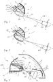
- a first variant of the light-guiding element 1 of the laser vehicle headlamp according to the invention is shown.
- the light guide 1 comes in a laser vehicle headlight 2 (see Fig. 3 ), for example, between a laser light source 3 and a luminous element 4, which is excited by the incident light from the laser light source 3 for the emission of visible light, in particular white color.
- a laser light source 3 is shown in two different positions, as will be explained in more detail below.
- the light-guiding element 1 is preferably made of a transparent material such as glass or plastic. It can be designed as a one-piece volumetric body, in a variant but also as a hollow body. The assembly of several volume bodies of different materials is possible.
- the light guide 1 has on a first side 10, which in the mounted state, as in Fig. 1 is indicated on the side of the laser light source 3, a light entrance surface 5. Via the light entry surface 5, which occupies part of the first side 10, laser light coming from the laser light source 3 can be irradiated into the light guide element 1.
- a light exit surface 60 which forms part of the second side 20. Furthermore, the second side 20 is assigned a recess 7 for a lighting element 4.
- the recess 7 is executed in the illustrated embodiment as a blind hole, but may for example be designed as completely surrounded by the light guide 1 cavity.
- the light entry surface 5 is associated with a first reflection region 50 oriented in the direction of the interior of the light guide element 1.
- the light-guiding element 1 or its outer side is designed as a free-form surface.
- Fig. 1 shows the laser light source 3 in two positions A, B. In position A, the laser light source 3 is positioned so that the light beam 200 is incident directly on the light-emitting element 4.
- Position B represents a situation in which the relative positioning between laser light source 3 and light guide 1 is not optimal.
- the light beam 200 is incident at a certain angle of deviation compared to the position A.
- the deviation angle 400 thus denotes the angle between the "optimal" light beam path with laser light source 3 in position A and a slightly shifted light beam path with laser light source 3 in position B.
- Such a situation may occur, for example, when there is a shift of the laser light source 3 due to vibrations during operation or improper replacement of the light source.
- the laser light source 3 is in position B, the light beam 200 'does not impinge directly on the luminous element 4, but on the first reflection region 50, from which it is reflected in the direction of the receptacle 7 for the luminous element 4.
- total reflection occurs in the first reflection region 50; in variants of the invention, however, a reflective coating can also be provided on the outside of the light-conducting element 1 in the region of the first reflection region 50.
- the incident light therefore does not have to impinge perpendicularly on the light entry surface 5, but can be noticed within an acceptance angle.
- the acceptance angle denotes the maximum angle at which light can be incident and still be directed to the luminous element 4.
- Light incident at an angle greater than the acceptance angle is either reflected directly at the light entry surface 5 or deflected in a manner in the light guide element 1 such that it does not reach the luminous element 4.
- the deviation angle 400 must therefore be less than or equal to the acceptance angle for a proper function.
- the design of the light entry surface 5 and the first reflection region 50 therefore increases the tolerances with which the light from the laser light source 3 radiates onto the light element 4 and thus facilitates the construction of a laser vehicle headlight 2 on the one hand (please refer Fig. 3 ), on the other hand, the vibrations occurring during operation are less significant.
- the light exit surface 6 on the second side 20 of the light guide element 1 is associated with a second reflection region 60 oriented in the direction of the interior of the light guide element 1.
- the light-guiding element 1 is also formed in the region of the second reflection region 60 as a free-form surface of known type.
- the light-guiding element 1 can also be embodied differently both in the region of the first 50 and the second reflection region 60, for example as a paraboloid surface or otherwise.
- the second reflection region 60 is arranged predominantly on a side of the light-guiding element 1 facing the laser light source 3 in the mounted state of the light-guiding element 1.
- the second reflection region 60 reflects light emanating from the luminous element 4 in the direction of the light exit surface 6. This makes possible the most complete possible utilization of the visible light emitted by the luminous element 4 - light that is radiated, for example, by the luminous element 4 in the direction of the laser light source 3 would otherwise not be usable ,
- the second reflection region 60 is formed as a reflection layer 8 applied on the outside of the light guide element 1.
- the reflection layer 8 is generated, for example, by painting or vapor deposition. In a variant, however, it can also be designed as a reflection element, which is positively applied to the light guide element 1, for example by gluing.
- the reflection layer 8 is covered on its outside with an absorption layer 9. This has the purpose of effectively preventing the reflection layer 8 from penetrating through it - especially when applying by means of vapor deposition it can sometimes lead to coating defects, so that in some places the reflection layer 8 is too thin or possibly even absent. In such cases, by applying the absorption layer 9, a radiation through the reflection layer 8 and thus a disturbance of the light image is prevented.
- the first reflection region 50 is constructed without such layers (deflection by means of total reflection). Together with the embodiment of the light-guiding element 1 in the region of the first 50 and second reflection region 60 - in the illustrated embodiment, as described above, each as a freeform surface - resulting in the reflection properties.
- the second reflection region 60 is designed with at least one focal point 11.
- the focal point 11 is located in the region of the light exit surface 6. This results in addition to the luminous element 4 as a real light source and a virtual light source at the location of said focal point 11th Derart, the luminous flux of the light distribution can be increased.
- the light-guiding element 1 emits visible light both from the luminous element 4 and from the virtual light source at the focal point 11.
- Fig. 2 now shows a second variant of the light-guiding element 1 of the laser vehicle headlamp according to the invention.
- a reflection layer 8 ' is also formed in the region of the first reflection region 50 on the outside of the light-guiding element 1.
- the second side 20 is provided in the region of the receptacle 7 for the luminous element 4 with an opaque limiting element 13.
- the limiting element 13 is provided in regions and can cover different areas of the second side 20.
- the limiting element 13 serves to influence the emitted light distribution - for example, this can produce a low beam with a sharp light-dark transition or other light functions.
- the outside of the light guide 1 at least partially, but in particular completely with an opaque and / or reflective coating be provided. This prevents light from escaping uncontrollably from the light guide element 1 and thus disturbing the light image (for example of a vehicle headlight 2, in which such a light guide element 1 is used).
- the shape of the light-guiding element 1 can be chosen differently.
- the light-guiding element body in the region of the first reflection region 50 is designed as a free-form surface similar to a rotation parabloid, in the region of the second Reflection region 60 as a free-form surface similar to an ellipsoidal shape.
- the execution of free-form surfaces of other types is possible, so that so that the photograph meets the legal requirements or homogeneity requirements.
- Fig. 3 shows a partial cross-sectional view of a vehicle headlight 2 with a light guide element 1 described above. Only the essential features for understanding the invention are shown, since the skilled person the other elements of a vehicle headlamp are known.
- the vehicle headlight 2 comprises a laser light source 3, which emits, for example, in a wavelength range between 200 nm and 450 nm, that is partially in the non-visible UV range.
- the radiated power of the laser light source 3 is between 0.5 and 2 W, but may be higher.
- the laser light source 3 is, for example, a semiconductor laser in the form of a laser diode. It is also possible to provide a plurality of laser light sources 3, for example in the form of laser diode arrays.
- the laser light source 3 has to dissipate the heat generated during operation in the illustrated embodiment, a heat sink 15 and a ventilation device 16 - the ventilation device 16 serves here, the cooling body 15 to supply cool air or dissipate heated air.
- the ventilation device 16 may for example comprise a ventilation device.
- the heat sink 15 may be made of a suitable material and in addition, for example, cooling fins or the like. exhibit.
- a luminous element 4 is provided which is spherical in the present embodiment.
- the spherical design is only one of several possible configurations, the light-emitting element 4 can also be designed differently.
- the luminous element 4 is preferably a phosphor converter, which can be excited by the light of the laser light source 3 in a known manner to emit visible light.
- all materials which convert monochromatic laser light into light of other wavelengths preferably white light
- the phosphorus converter is thus a light converter - the electrons of the converter material are transformed into higher energy levels by the laser light excited and emit when falling back light of the level difference corresponding wavelength.
- the luminous element 4 is arranged in a light-guiding element 1 of the laser vehicle headlamp according to the invention, which is positioned in a reflector 17.
- the light guide 1 is the variant according to Fig. 1
- both the luminous element 4 and the rays reflected by the second reflection region 60 contribute to the light distribution emitted via the reflector 17.
- the variant according to Fig. 2 or other embodiments are used.
- the reflector 17 directs the light emitted by the luminous element 4 in the main emission direction 100 of the vehicle headlight 2.
- the main emission direction 100 extends in the present example in FIG Fig. 3 left to right.
- the reflector 17 may be arranged to be pivotable and / or adjustable, which is not shown in the figures for reasons of clarity. Basically, any embodiments of the reflector 17 are possible, it can free-form variants as well as parabolas, hyperbola, ellipses or combinations thereof come as a reflector surface are used.
- the reflector 17 is in Fig. 3 shown in cross-section and can be designed as a half-shell (only the upper or lower half is available) or as a full reflector, the skilled person a number of variants for the reflector 17 is known.
- the luminous element 4 is arranged on the optical axis 200 of the vehicle headlight 2 in a focal point of the reflector 17.
- the reflector 17 may also be designed as an open-space reflector with a plurality of different focal points, wherein according to the illustrated embodiment, the light-emitting element 4 is arranged precisely in one of these focal points.
- the vehicle headlight 2 is closed by a cover 18.
- the cover 18 may be arbitrary, but is preferably largely transparent.
- the desired light pattern of the vehicle headlight 2 is generated by the light guide element 1, the luminous element 4 arranged therein and the reflector 17. Also allows the light guide 1 of the laser vehicle headlamp according to the invention greater tolerances with respect to the relative positioning between the laser light source 3 and light element 4, for example when the light source 3 is replaced due to repair or if the laser light source 3 is no longer in optimal position due to vibrations during operation. At the same time, the use of the light emitted by the light guide 4 forward, ie in the main emission 100 of the vehicle headlamp 2 light is possible.
- a carrier element 19 is provided - the carrier element 19 is here provided with cooling ribs 21, which serve to dissipate the heat generated during the light generation in the luminous element 4 and the light-guiding element 1.
- the cooling fins 21 are only one example of heat sinks that may be used herein - the skilled person is aware of a number of possibilities in this respect, so will not be discussed in detail here.
- the laser light source 3 and the luminous element 4 are arranged so that the light of the laser light source 3 is emitted counter to the main emission direction 100 of the vehicle headlamp 2.
- the laser light source 3 is therefore arranged in the main emission direction 100 of the vehicle headlamp 2 in front of the luminous element 4, so that the light of the laser light source 3 is emitted counter to the main emission direction 100 of the vehicle headlamp 2.
- the beam direction 300 of the laser light source 3 thus runs opposite to the main emission direction 100 of the vehicle headlight 2. This prevents that in the event of damage to the vehicle headlight 2 or a malfunction, the light of the laser light source 3 escape and can endanger other road users.
- the beam direction 300 of the laser light source 3 preferably extends at an acute angle to the main emission direction 100 of the vehicle headlight 2.
- the angle can therefore be between 0 ° and 90 °.
- An angle of 0 ° thus means that the laser light source 3 is arranged on the optical axis of the vehicle headlight 2 in the main beam direction 100 behind the luminous element 4.
- an angle of 90 ° means that the beam direction 300 of the laser light source 3 is normal to the optical axis of the vehicle headlight 2.
- Optical axis and main emission direction 100 of the vehicle headlight 2 are substantially parallel to each other. Depending on the available space for the vehicle headlight 2 or desired field of application so light source 3 and light guide 1 or lighting element 4 are arranged to each other.
- a number of elements can be arranged.
- an optical element in the form of a collecting lens element 22 This converging lens concentrates the light of the laser light source 3 in the direction of the light-guiding element 1 or of the luminous element 4 arranged therein.
- any other optical elements may also be used, for example lenses and / or prisms of various kinds.
- absorbing elements are arranged around such optical or light-guiding elements 1 in order to prevent any reflections of the incoming laser light in the main emission direction 100 of the vehicle headlight 2 and thus endanger other road users.
- an aperture element 14 is shown. It prevents radiation of reflections from the vehicle headlight 2 out.
- the said optical, light-guiding elements 1 and absorbing elements such as the diaphragm element 14 may also be provided with anti-reflective surfaces or designed so that they only reflect or absorb light in the wavelength range of the laser light, but translucent for visible light are executed and thus allow a look at the headlight components. In this case, irregularities such as inclusions or microstructures can be provided, which deflect the laser light, make visible from the outside and thus serve as a design element.
- the diaphragm element 14 is in FIG Fig. 3 arranged above a horizontal plane extending through the optical axis 200 of the vehicle headlight 2 between the light guide 1 and the cover 18.
- the light functions of the vehicle headlamp 2 are not adversely affected.
- the diaphragm element 14 can also be designed so that it covers the entire free-jet region of the laser light, for example in the form of a tube or a tube with a semicircular cross-section ("half-pipe"). In another variant, it can be semi-mirrored be executed and / or illuminated for design reasons with its own light source (eg a blue LED). Such variants are not shown in the figures.
- the invention according to the above embodiments allows the realization of a vehicle headlamp, which can meet the legal requirements such as ECE, SAE, CCC, etc.
- the heat generated during operation of the laser light source 3 waste heat can be used.
- the laser light source 3 below a in the installed state of the vehicle headlamp 2 by the optical axis 200 of the vehicle headlamp 2 extending horizontal plane close to the cover 18 is arranged.
- the horizontal plane runs in Fig. 3 normal to the plane of the drawing through the optical axis 200 of the vehicle headlight 2.
- the laser light source 3 is arranged so close to the cover 18 that the cover 18 can be heated by means of the waste heat of the laser light source 3.
- the waste heat can be used for defrosting and deicing the cover 18.
- the ventilation device 16 of the laser light source 3 can be used here by supporting the waste heat flow supportive.
- the laser light source 3 is positioned under a design shutter element 23 having corresponding design apertures 24 for the passage of the waste heat.
- These design apertures 24 may according to a variant have a nozzle-like shape, so that caused by the waste heat of the laser light source 3 air flow 25 can be targeted.
- nozzle-like shape is here to be understood a shape that allows the steering of the design aperture 24 passing through the air flow 25 in order to achieve the above-mentioned object.
- the defrosting and deicing, or more generally the benefits of the waste heat of the laser light source 3 can be done even more efficient.
Landscapes
- Engineering & Computer Science (AREA)
- General Engineering & Computer Science (AREA)
- Physics & Mathematics (AREA)
- Optics & Photonics (AREA)
- Non-Portable Lighting Devices Or Systems Thereof (AREA)
Claims (13)
- Phare laser de véhicule (2) comportant au moins un élément guide de lumière (1), au moins une source de lumière laser (3) et au moins un élément lumineux (4) pouvant être irradié par la source de lumière laser (3) et pouvant ainsi être excité pour émettre de la lumière visible, caractérisé par le fait que l'élément guide de lumière (1) présente un premier côté (10), qui est conçu au moins partiellement en tant que surface d'entrée de lumière (5), et un second côté (20) disposé à l'opposé du premier côté (10), qui est conçu au moins partiellement en tant que surface de sortie de lumière (6) et auquel est associé au moins une cavité (7) pour le au moins un élément lumineux (4), au moins une première zone de réflexion (50) orientée en direction de l'intérieur de l'élément guide de lumière (1), réfléchissant de la lumière provenant de la surface d'entrée de lumière (5) en direction de la cavité (7) pour l'élément lumineux (4) étant associée à la surface d'entrée de lumière (5), et au moins une seconde zone de réflexion (60) orientée en direction de l'intérieur de l'élément guide de lumière (1), réfléchissant de la lumière provenant de l'élément lumineux (4) en direction de la surface de sortie de lumière (6) étant associée à la surface de sortie de lumière (6).
- Phare laser de véhicule (2) selon la revendication 1, caractérisé par le fait que la seconde zone de réflexion (60) est disposée principalement sur le côté de l'élément guide de lumière (1) tourné vers la source de lumière laser (3) à l'état monté de l'élément guide de lumière (1).
- Phare laser de véhicule (2) selon l'une des revendications 1 ou 2, caractérisé par le fait que la seconde zone de réflexion (60) et/ou la première zone de réflexion (50) sont conçues en tant qu'au moins une couche de réflexion (8, 8') appliquée sur le côté externe de l'élément guide de lumière (1), qui de préférence est recouverte par une couche d'absorption (9, 9').
- Phare laser de véhicule (2) selon l'une des revendications précédentes, caractérisé par le fait que l'élément guide de lumière (1) est conçu en tant que surface de forme libre dans la zone de la première (50) et/ou de la seconde zone de réflexion (60).
- Phare laser de véhicule (2) selon la revendication 4, caractérisé par le fait que la première (50) et/ou la seconde zone de réflexion (60) sont réalisées avec au moins un point focal (11).
- Phare laser de véhicule (2) selon l'une des revendications 4 ou 5, caractérisé par le fait que la seconde zone de réflexion (60) présente au moins un point focal (11) dans la zone de la surface de sortie de lumière (6).
- Phare laser de véhicule (2) selon l'une des revendications précédentes, caractérisé par le fait que la cavité (7) pour l'élément lumineux (4) est réalisé en tant que trou borgne ou en tant que cavité entourée entièrement par l'élément guide de lumière (1).
- Phare laser de véhicule (2) selon l'une des revendications précédentes, caractérisé par le fait que le côté externe de l'élément guide de lumière (1) à l'exception de la surface d'entrée de lumière (5), de la surface de sortie de lumière (6) et des zones de réflexion (50, 60), est doté au moins par endroits, mais en particulier entièrement, d'un revêtement (12) opaque et/ou réfléchissant.
- Phare laser de véhicule (2) selon l'une des revendications précédentes, caractérisé par le fait que le second côté (20) est recouvert au moins par endroits d'un élément de délimitation (13) opaque, qui est disposé de préférence dans la zone de la cavité (7) pour le au moins un élément lumineux (4).
- Phare laser de véhicule (2) selon l'une des revendications précédentes, caractérisé par le fait qu'au moins un élément guide de lumière (1) est disposé entre la source de lumière laser (3) et l'élément lumineux (4).
- Phare laser de véhicule (2) selon l'une des revendications précédentes, caractérisé par le fait que la source de lumière laser (3) est disposée devant l'élément lumineux (4) tel que vu dans la direction de rayonnement principale (100) du phare de véhicule (2), de telle sorte que la lumière de la source de lumière laser (3) est émise contre la direction de rayonnement principale (100) du phare de véhicule (2).
- Phare laser de véhicule (2) selon l'une des revendications précédentes, caractérisé par le fait qu'au moins un élément écran (14) est prévu, avec lequel de la lumière réfléchie par la surface d'entrée de lumière (5) de l'élément guide de lumière (1) ou depuis l'intérieur de l'élément guide de lumière (1) dans la direction de rayonnement principale (100) du phare de véhicule (2) peut être arrêtée.
- Phare laser de véhicule (2) selon l'une des revendications précédentes, caractérisé par le fait que l'élément écran (14) est réalisé en tant que pièce de liaison s'étendant entre la source de lumière laser (3) et l'élément guide de lumière (1), qui est réalisée en particulier de forme tubulaire ou de forme semi-tubulaire.
Applications Claiming Priority (2)
| Application Number | Priority Date | Filing Date | Title |
|---|---|---|---|
| ATA50071/2012A AT512590B1 (de) | 2012-03-12 | 2012-03-12 | Lichtleitelement für einen Laser-Fahrzeugscheinwerfer sowie Fahrzeugscheinwerfer |
| PCT/AT2013/050049 WO2013134803A1 (fr) | 2012-03-12 | 2013-02-28 | Élément guide de lumière pour projecteur de véhicule |
Publications (2)
| Publication Number | Publication Date |
|---|---|
| EP2802807A1 EP2802807A1 (fr) | 2014-11-19 |
| EP2802807B1 true EP2802807B1 (fr) | 2017-10-18 |
Family
ID=48047762
Family Applications (1)
| Application Number | Title | Priority Date | Filing Date |
|---|---|---|---|
| EP13714181.8A Active EP2802807B1 (fr) | 2012-03-12 | 2013-02-28 | Projecteur de véhicule du type laser |
Country Status (8)
| Country | Link |
|---|---|
| US (1) | US9677733B2 (fr) |
| EP (1) | EP2802807B1 (fr) |
| JP (1) | JP6108185B2 (fr) |
| CN (1) | CN104160209B (fr) |
| AT (1) | AT512590B1 (fr) |
| IN (1) | IN2014MN01972A (fr) |
| MX (1) | MX2014010936A (fr) |
| WO (1) | WO2013134803A1 (fr) |
Families Citing this family (21)
| Publication number | Priority date | Publication date | Assignee | Title |
|---|---|---|---|---|
| AT513816B1 (de) | 2012-12-20 | 2015-11-15 | Zizala Lichtsysteme Gmbh | Lichtführungseinheit für eine Leuchteinheit eines Scheinwerfers sowie Leuchteinheit und Schweinwerfer |
| JP2015005439A (ja) * | 2013-06-21 | 2015-01-08 | スタンレー電気株式会社 | 車両用前照灯及び車両用前照灯に用いられる光ファイババンドル |
| PL3267427T3 (pl) * | 2013-10-10 | 2019-10-31 | Ortana Elektronik Yazilim Taah San Ve Tic A S | Element optyczny dla systemu informacyjnego do wyświetlania informacji |
| DE102014118403A1 (de) | 2014-04-07 | 2015-10-08 | Dr. Ing. H.C. F. Porsche Aktiengesellschaft | Kraftfahrzeugscheinwerfer |
| DE102014222903A1 (de) | 2014-11-10 | 2016-05-12 | Automotive Lighting Reutlingen Gmbh | Laserlichtmodul für eine Kraftfahrzeugbeleuchtungseinrichtung |
| GB2535534B (en) * | 2015-02-23 | 2018-11-14 | Jaguar Land Rover Ltd | Illumination device, method and system |
| FR3038738B1 (fr) * | 2015-07-08 | 2017-08-11 | Valeo Vision | Dispositif optique comportant au moins un convertisseur de longueur d’onde, module lumineux et dispositif d’eclairage pour vehicule automobile comportant un tel dispositif |
| KR101755830B1 (ko) * | 2015-08-27 | 2017-07-10 | 현대자동차주식회사 | 차량용 램프 장치 |
| DE102015120223A1 (de) * | 2015-11-23 | 2017-05-24 | Dr. Ing. H.C. F. Porsche Aktiengesellschaft | Lichtleitelement für einen Fahrzeugscheinwerfer |
| DE102015226724A1 (de) * | 2015-12-23 | 2017-06-29 | Automotive Lighting Reutlingen Gmbh | Lichtmodul für eine Beleuchtungseinrichtung eines Kraftfahrzeugs |
| WO2018051791A1 (fr) * | 2016-09-13 | 2018-03-22 | 本田技研工業株式会社 | Dispositif de phare |
| TWI615581B (zh) * | 2017-07-14 | 2018-02-21 | 達運精密工業股份有限公司 | 光反射罩及具有光反射罩的照明裝置 |
| DE102018101036A1 (de) * | 2018-01-18 | 2019-07-18 | HELLA GmbH & Co. KGaA | Heckleuchte für ein Kraftfahrzeug |
| US12000552B2 (en) * | 2019-01-18 | 2024-06-04 | Kyocera Sld Laser, Inc. | Laser-based fiber-coupled white light system for a vehicle |
| US12152742B2 (en) | 2019-01-18 | 2024-11-26 | Kyocera Sld Laser, Inc. | Laser-based light guide-coupled wide-spectrum light system |
| CN112050162A (zh) * | 2019-06-05 | 2020-12-08 | 华域视觉科技(上海)有限公司 | 一种车灯光学元件、车灯模组及车辆 |
| DE102020112312B3 (de) * | 2020-05-06 | 2021-10-21 | Audi Aktiengesellschaft | Scheinwerfer für ein Kraftfahrzeug |
| US11255508B2 (en) | 2020-06-15 | 2022-02-22 | Grote Industries, Inc. | Deicing system for an automotive lamp |
| US12158255B2 (en) | 2020-06-15 | 2024-12-03 | Grote Industries, Inc. | Deicing system for an automotive lamp |
| KR20240152007A (ko) * | 2023-04-12 | 2024-10-21 | 현대모비스 주식회사 | 이동체 후방용 리어 램프 시스템 및 그 제어방법 |
| DE102024104622A1 (de) * | 2024-02-20 | 2025-08-21 | Miele & Cie. Kg | Lichtleitkanal für eine Beleuchtungsvorrichtung und Beleuchtungsvorrichtung für ein Haushaltsgerät |
Family Cites Families (13)
| Publication number | Priority date | Publication date | Assignee | Title |
|---|---|---|---|---|
| AU734727B2 (en) | 1997-12-05 | 2001-06-21 | Interag | Improvements in and/or relating to delivery devices and their use |
| JP4124445B2 (ja) * | 2003-02-03 | 2008-07-23 | 株式会社小糸製作所 | 光源及び車両用前照灯 |
| JP4047266B2 (ja) * | 2003-11-19 | 2008-02-13 | 株式会社小糸製作所 | 灯具 |
| JP4729441B2 (ja) * | 2006-06-09 | 2011-07-20 | スタンレー電気株式会社 | 車両用灯具 |
| JP5118564B2 (ja) | 2008-06-24 | 2013-01-16 | 株式会社小糸製作所 | 車両用灯具 |
| KR101834893B1 (ko) * | 2009-04-09 | 2018-03-08 | 필립스 라이팅 홀딩 비.브이. | 레이저 응용을 위한 램프 |
| JP2011129376A (ja) * | 2009-12-17 | 2011-06-30 | Sharp Corp | 発光装置、照明装置、車両用ヘッドランプおよびプロジェクタ |
| JP4991834B2 (ja) * | 2009-12-17 | 2012-08-01 | シャープ株式会社 | 車両用前照灯 |
| JP5530187B2 (ja) * | 2010-01-07 | 2014-06-25 | スタンレー電気株式会社 | 光源装置および照明装置 |
| JP2011157022A (ja) | 2010-02-03 | 2011-08-18 | Sharp Corp | 前照灯および移動体 |
| JP5059208B2 (ja) * | 2010-04-07 | 2012-10-24 | シャープ株式会社 | 照明装置および車両用前照灯 |
| JP5577138B2 (ja) | 2010-04-08 | 2014-08-20 | スタンレー電気株式会社 | 車両用前照灯 |
| JP5526452B2 (ja) * | 2010-09-10 | 2014-06-18 | スタンレー電気株式会社 | 車両用灯具ユニット |
-
2012
- 2012-03-12 AT ATA50071/2012A patent/AT512590B1/de not_active IP Right Cessation
-
2013
- 2013-02-28 WO PCT/AT2013/050049 patent/WO2013134803A1/fr not_active Ceased
- 2013-02-28 JP JP2014561226A patent/JP6108185B2/ja not_active Expired - Fee Related
- 2013-02-28 MX MX2014010936A patent/MX2014010936A/es active IP Right Grant
- 2013-02-28 EP EP13714181.8A patent/EP2802807B1/fr active Active
- 2013-02-28 US US14/384,243 patent/US9677733B2/en not_active Expired - Fee Related
- 2013-02-28 CN CN201380014088.6A patent/CN104160209B/zh active Active
-
2014
- 2014-10-01 IN IN1972MUN2014 patent/IN2014MN01972A/en unknown
Non-Patent Citations (1)
| Title |
|---|
| None * |
Also Published As
| Publication number | Publication date |
|---|---|
| AT512590A1 (de) | 2013-09-15 |
| MX2014010936A (es) | 2014-11-13 |
| EP2802807A1 (fr) | 2014-11-19 |
| WO2013134803A1 (fr) | 2013-09-19 |
| AT512590B1 (de) | 2013-11-15 |
| JP2015513382A (ja) | 2015-05-11 |
| CN104160209A (zh) | 2014-11-19 |
| US20150078022A1 (en) | 2015-03-19 |
| US9677733B2 (en) | 2017-06-13 |
| CN104160209B (zh) | 2017-06-30 |
| IN2014MN01972A (fr) | 2015-07-03 |
| JP6108185B2 (ja) | 2017-04-05 |
Similar Documents
| Publication | Publication Date | Title |
|---|---|---|
| EP2802807B1 (fr) | Projecteur de véhicule du type laser | |
| EP2825818B1 (fr) | Élément guide de lumière pour projecteur de véhicule | |
| EP2745042B1 (fr) | Phare de véhicule avec source lumineuse à laser | |
| EP2800677B1 (fr) | Diode laser servant de source de lumière standard | |
| DE102010056313C5 (de) | Beleuchtungseinrichtung eines Kraftfahrzeugs | |
| DE102008036194B4 (de) | Lichtmodul für eine Beleuchtungseinrichtung für ein Kraftfahrzeug | |
| EP2795183B1 (fr) | Élément optique pour projecteur laser de véhicule | |
| DE102008045032A1 (de) | Fahrzeuglampeneinheit | |
| DE102012206397B4 (de) | Leuchtvorrichtung mit einer Blende, deren eine Seite von einer ersten Lichtquelle über einen Reflektor bestrahlt wird und deren andere, mit einem Leuchtstoff belegte Seite von einer zweiten Lichtquelle bestrahlt wird | |
| WO2012119976A1 (fr) | Projecteur de véhicule automobile équipé d'un module de projection multifonction | |
| DE102007040760A1 (de) | Projektionsmodul eines Fahrzeugscheinwerfers | |
| DE102012215711A1 (de) | Fahrzeugbeleuchtungsvorrichtung | |
| DE102007040728A1 (de) | Fahrzeugscheinwerfer | |
| WO2019076550A1 (fr) | Dispositif d'éclairage pour phare de véhicule automobile | |
| EP2500630B1 (fr) | Optique transparente ou lentille d'un dispositif d'éclairage d'un véhicule automobile | |
| DE102015202745B4 (de) | Fahrzeugbeleuchtungsvorrichtung | |
| WO2015043819A1 (fr) | Dispositif d'éclairage pour véhicule automobile | |
| WO2016096602A1 (fr) | Dispositif luminescent doté d'un luminophore | |
| DE102011087309A1 (de) | Leuchtvorrichtung | |
| DE102011087308B4 (de) | Leuchtvorrichtung mit Reflektor, Linse und Blende | |
| DE102018111040A1 (de) | Lichtmodul einer Kraftfahrzeugbeleuchtungseinrichtung |
Legal Events
| Date | Code | Title | Description |
|---|---|---|---|
| PUAI | Public reference made under article 153(3) epc to a published international application that has entered the european phase |
Free format text: ORIGINAL CODE: 0009012 |
|
| 17P | Request for examination filed |
Effective date: 20140814 |
|
| AK | Designated contracting states |
Kind code of ref document: A1 Designated state(s): AL AT BE BG CH CY CZ DE DK EE ES FI FR GB GR HR HU IE IS IT LI LT LU LV MC MK MT NL NO PL PT RO RS SE SI SK SM TR |
|
| DAX | Request for extension of the european patent (deleted) | ||
| RAP1 | Party data changed (applicant data changed or rights of an application transferred) |
Owner name: ZKW GROUP GMBH |
|
| GRAP | Despatch of communication of intention to grant a patent |
Free format text: ORIGINAL CODE: EPIDOSNIGR1 |
|
| INTG | Intention to grant announced |
Effective date: 20170518 |
|
| GRAS | Grant fee paid |
Free format text: ORIGINAL CODE: EPIDOSNIGR3 |
|
| GRAA | (expected) grant |
Free format text: ORIGINAL CODE: 0009210 |
|
| AK | Designated contracting states |
Kind code of ref document: B1 Designated state(s): AL AT BE BG CH CY CZ DE DK EE ES FI FR GB GR HR HU IE IS IT LI LT LU LV MC MK MT NL NO PL PT RO RS SE SI SK SM TR |
|
| REG | Reference to a national code |
Ref country code: GB Ref legal event code: FG4D Free format text: NOT ENGLISH |
|
| REG | Reference to a national code |
Ref country code: CH Ref legal event code: EP |
|
| REG | Reference to a national code |
Ref country code: AT Ref legal event code: REF Ref document number: 938271 Country of ref document: AT Kind code of ref document: T Effective date: 20171115 Ref country code: IE Ref legal event code: FG4D Free format text: LANGUAGE OF EP DOCUMENT: GERMAN |
|
| REG | Reference to a national code |
Ref country code: DE Ref legal event code: R079 Ref document number: 502013008601 Country of ref document: DE Free format text: PREVIOUS MAIN CLASS: F21S0008100000 Ipc: F21S0043000000 |
|
| REG | Reference to a national code |
Ref country code: DE Ref legal event code: R096 Ref document number: 502013008601 Country of ref document: DE |
|
| REG | Reference to a national code |
Ref country code: FR Ref legal event code: PLFP Year of fee payment: 6 |
|
| REG | Reference to a national code |
Ref country code: NL Ref legal event code: MP Effective date: 20171018 |
|
| REG | Reference to a national code |
Ref country code: LT Ref legal event code: MG4D |
|
| PG25 | Lapsed in a contracting state [announced via postgrant information from national office to epo] |
Ref country code: NL Free format text: LAPSE BECAUSE OF FAILURE TO SUBMIT A TRANSLATION OF THE DESCRIPTION OR TO PAY THE FEE WITHIN THE PRESCRIBED TIME-LIMIT Effective date: 20171018 |
|
| PG25 | Lapsed in a contracting state [announced via postgrant information from national office to epo] |
Ref country code: SE Free format text: LAPSE BECAUSE OF FAILURE TO SUBMIT A TRANSLATION OF THE DESCRIPTION OR TO PAY THE FEE WITHIN THE PRESCRIBED TIME-LIMIT Effective date: 20171018 Ref country code: ES Free format text: LAPSE BECAUSE OF FAILURE TO SUBMIT A TRANSLATION OF THE DESCRIPTION OR TO PAY THE FEE WITHIN THE PRESCRIBED TIME-LIMIT Effective date: 20171018 Ref country code: FI Free format text: LAPSE BECAUSE OF FAILURE TO SUBMIT A TRANSLATION OF THE DESCRIPTION OR TO PAY THE FEE WITHIN THE PRESCRIBED TIME-LIMIT Effective date: 20171018 Ref country code: NO Free format text: LAPSE BECAUSE OF FAILURE TO SUBMIT A TRANSLATION OF THE DESCRIPTION OR TO PAY THE FEE WITHIN THE PRESCRIBED TIME-LIMIT Effective date: 20180118 Ref country code: LT Free format text: LAPSE BECAUSE OF FAILURE TO SUBMIT A TRANSLATION OF THE DESCRIPTION OR TO PAY THE FEE WITHIN THE PRESCRIBED TIME-LIMIT Effective date: 20171018 |
|
| PG25 | Lapsed in a contracting state [announced via postgrant information from national office to epo] |
Ref country code: GR Free format text: LAPSE BECAUSE OF FAILURE TO SUBMIT A TRANSLATION OF THE DESCRIPTION OR TO PAY THE FEE WITHIN THE PRESCRIBED TIME-LIMIT Effective date: 20180119 Ref country code: LV Free format text: LAPSE BECAUSE OF FAILURE TO SUBMIT A TRANSLATION OF THE DESCRIPTION OR TO PAY THE FEE WITHIN THE PRESCRIBED TIME-LIMIT Effective date: 20171018 Ref country code: HR Free format text: LAPSE BECAUSE OF FAILURE TO SUBMIT A TRANSLATION OF THE DESCRIPTION OR TO PAY THE FEE WITHIN THE PRESCRIBED TIME-LIMIT Effective date: 20171018 Ref country code: IS Free format text: LAPSE BECAUSE OF FAILURE TO SUBMIT A TRANSLATION OF THE DESCRIPTION OR TO PAY THE FEE WITHIN THE PRESCRIBED TIME-LIMIT Effective date: 20180218 Ref country code: RS Free format text: LAPSE BECAUSE OF FAILURE TO SUBMIT A TRANSLATION OF THE DESCRIPTION OR TO PAY THE FEE WITHIN THE PRESCRIBED TIME-LIMIT Effective date: 20171018 Ref country code: BG Free format text: LAPSE BECAUSE OF FAILURE TO SUBMIT A TRANSLATION OF THE DESCRIPTION OR TO PAY THE FEE WITHIN THE PRESCRIBED TIME-LIMIT Effective date: 20180118 |
|
| REG | Reference to a national code |
Ref country code: DE Ref legal event code: R097 Ref document number: 502013008601 Country of ref document: DE |
|
| PG25 | Lapsed in a contracting state [announced via postgrant information from national office to epo] |
Ref country code: EE Free format text: LAPSE BECAUSE OF FAILURE TO SUBMIT A TRANSLATION OF THE DESCRIPTION OR TO PAY THE FEE WITHIN THE PRESCRIBED TIME-LIMIT Effective date: 20171018 Ref country code: CZ Free format text: LAPSE BECAUSE OF FAILURE TO SUBMIT A TRANSLATION OF THE DESCRIPTION OR TO PAY THE FEE WITHIN THE PRESCRIBED TIME-LIMIT Effective date: 20171018 Ref country code: DK Free format text: LAPSE BECAUSE OF FAILURE TO SUBMIT A TRANSLATION OF THE DESCRIPTION OR TO PAY THE FEE WITHIN THE PRESCRIBED TIME-LIMIT Effective date: 20171018 Ref country code: SK Free format text: LAPSE BECAUSE OF FAILURE TO SUBMIT A TRANSLATION OF THE DESCRIPTION OR TO PAY THE FEE WITHIN THE PRESCRIBED TIME-LIMIT Effective date: 20171018 |
|
| PLBE | No opposition filed within time limit |
Free format text: ORIGINAL CODE: 0009261 |
|
| STAA | Information on the status of an ep patent application or granted ep patent |
Free format text: STATUS: NO OPPOSITION FILED WITHIN TIME LIMIT |
|
| PG25 | Lapsed in a contracting state [announced via postgrant information from national office to epo] |
Ref country code: IT Free format text: LAPSE BECAUSE OF FAILURE TO SUBMIT A TRANSLATION OF THE DESCRIPTION OR TO PAY THE FEE WITHIN THE PRESCRIBED TIME-LIMIT Effective date: 20171018 Ref country code: SM Free format text: LAPSE BECAUSE OF FAILURE TO SUBMIT A TRANSLATION OF THE DESCRIPTION OR TO PAY THE FEE WITHIN THE PRESCRIBED TIME-LIMIT Effective date: 20171018 Ref country code: PL Free format text: LAPSE BECAUSE OF FAILURE TO SUBMIT A TRANSLATION OF THE DESCRIPTION OR TO PAY THE FEE WITHIN THE PRESCRIBED TIME-LIMIT Effective date: 20171018 Ref country code: RO Free format text: LAPSE BECAUSE OF FAILURE TO SUBMIT A TRANSLATION OF THE DESCRIPTION OR TO PAY THE FEE WITHIN THE PRESCRIBED TIME-LIMIT Effective date: 20171018 |
|
| REG | Reference to a national code |
Ref country code: CH Ref legal event code: PL |
|
| 26N | No opposition filed |
Effective date: 20180719 |
|
| PG25 | Lapsed in a contracting state [announced via postgrant information from national office to epo] |
Ref country code: MC Free format text: LAPSE BECAUSE OF FAILURE TO SUBMIT A TRANSLATION OF THE DESCRIPTION OR TO PAY THE FEE WITHIN THE PRESCRIBED TIME-LIMIT Effective date: 20171018 Ref country code: MT Free format text: LAPSE BECAUSE OF FAILURE TO SUBMIT A TRANSLATION OF THE DESCRIPTION OR TO PAY THE FEE WITHIN THE PRESCRIBED TIME-LIMIT Effective date: 20171018 |
|
| GBPC | Gb: european patent ceased through non-payment of renewal fee |
Effective date: 20180228 |
|
| REG | Reference to a national code |
Ref country code: IE Ref legal event code: MM4A |
|
| REG | Reference to a national code |
Ref country code: BE Ref legal event code: MM Effective date: 20180228 |
|
| PG25 | Lapsed in a contracting state [announced via postgrant information from national office to epo] |
Ref country code: SI Free format text: LAPSE BECAUSE OF FAILURE TO SUBMIT A TRANSLATION OF THE DESCRIPTION OR TO PAY THE FEE WITHIN THE PRESCRIBED TIME-LIMIT Effective date: 20171018 Ref country code: LU Free format text: LAPSE BECAUSE OF NON-PAYMENT OF DUE FEES Effective date: 20180228 Ref country code: LI Free format text: LAPSE BECAUSE OF NON-PAYMENT OF DUE FEES Effective date: 20180228 Ref country code: CH Free format text: LAPSE BECAUSE OF NON-PAYMENT OF DUE FEES Effective date: 20180228 |
|
| PG25 | Lapsed in a contracting state [announced via postgrant information from national office to epo] |
Ref country code: IE Free format text: LAPSE BECAUSE OF NON-PAYMENT OF DUE FEES Effective date: 20180228 |
|
| PG25 | Lapsed in a contracting state [announced via postgrant information from national office to epo] |
Ref country code: GB Free format text: LAPSE BECAUSE OF NON-PAYMENT OF DUE FEES Effective date: 20180228 Ref country code: BE Free format text: LAPSE BECAUSE OF NON-PAYMENT OF DUE FEES Effective date: 20180228 |
|
| REG | Reference to a national code |
Ref country code: AT Ref legal event code: MM01 Ref document number: 938271 Country of ref document: AT Kind code of ref document: T Effective date: 20180228 |
|
| PG25 | Lapsed in a contracting state [announced via postgrant information from national office to epo] |
Ref country code: AT Free format text: LAPSE BECAUSE OF NON-PAYMENT OF DUE FEES Effective date: 20180228 |
|
| PG25 | Lapsed in a contracting state [announced via postgrant information from national office to epo] |
Ref country code: TR Free format text: LAPSE BECAUSE OF FAILURE TO SUBMIT A TRANSLATION OF THE DESCRIPTION OR TO PAY THE FEE WITHIN THE PRESCRIBED TIME-LIMIT Effective date: 20171018 |
|
| PG25 | Lapsed in a contracting state [announced via postgrant information from national office to epo] |
Ref country code: HU Free format text: LAPSE BECAUSE OF FAILURE TO SUBMIT A TRANSLATION OF THE DESCRIPTION OR TO PAY THE FEE WITHIN THE PRESCRIBED TIME-LIMIT; INVALID AB INITIO Effective date: 20130228 Ref country code: PT Free format text: LAPSE BECAUSE OF FAILURE TO SUBMIT A TRANSLATION OF THE DESCRIPTION OR TO PAY THE FEE WITHIN THE PRESCRIBED TIME-LIMIT Effective date: 20171018 |
|
| PG25 | Lapsed in a contracting state [announced via postgrant information from national office to epo] |
Ref country code: MK Free format text: LAPSE BECAUSE OF NON-PAYMENT OF DUE FEES Effective date: 20171018 Ref country code: CY Free format text: LAPSE BECAUSE OF FAILURE TO SUBMIT A TRANSLATION OF THE DESCRIPTION OR TO PAY THE FEE WITHIN THE PRESCRIBED TIME-LIMIT Effective date: 20171018 |
|
| PG25 | Lapsed in a contracting state [announced via postgrant information from national office to epo] |
Ref country code: AL Free format text: LAPSE BECAUSE OF FAILURE TO SUBMIT A TRANSLATION OF THE DESCRIPTION OR TO PAY THE FEE WITHIN THE PRESCRIBED TIME-LIMIT Effective date: 20171018 |
|
| P01 | Opt-out of the competence of the unified patent court (upc) registered |
Effective date: 20230528 |
|
| PGFP | Annual fee paid to national office [announced via postgrant information from national office to epo] |
Ref country code: FR Payment date: 20240221 Year of fee payment: 12 |
|
| REG | Reference to a national code |
Ref country code: DE Ref legal event code: R084 Ref document number: 502013008601 Country of ref document: DE |
|
| PG25 | Lapsed in a contracting state [announced via postgrant information from national office to epo] |
Ref country code: FR Free format text: LAPSE BECAUSE OF NON-PAYMENT OF DUE FEES Effective date: 20250228 |
|
| PGFP | Annual fee paid to national office [announced via postgrant information from national office to epo] |
Ref country code: DE Payment date: 20260217 Year of fee payment: 14 |