EP2802933B1 - Système optique pour former une image d'un objet - Google Patents
Système optique pour former une image d'un objet Download PDFInfo
- Publication number
- EP2802933B1 EP2802933B1 EP13700213.5A EP13700213A EP2802933B1 EP 2802933 B1 EP2802933 B1 EP 2802933B1 EP 13700213 A EP13700213 A EP 13700213A EP 2802933 B1 EP2802933 B1 EP 2802933B1
- Authority
- EP
- European Patent Office
- Prior art keywords
- unit
- image stabilization
- optical system
- image
- stabilization unit
- Prior art date
- Legal status (The legal status is an assumption and is not a legal conclusion. Google has not performed a legal analysis and makes no representation as to the accuracy of the status listed.)
- Active
Links
Images





Classifications
-
- G—PHYSICS
- G02—OPTICS
- G02B—OPTICAL ELEMENTS, SYSTEMS OR APPARATUS
- G02B27/00—Optical systems or apparatus not provided for by any of the groups G02B1/00 - G02B26/00, G02B30/00
- G02B27/64—Imaging systems using optical elements for stabilisation of the lateral and angular position of the image
- G02B27/646—Imaging systems using optical elements for stabilisation of the lateral and angular position of the image compensating for small deviations, e.g. due to vibration or shake
-
- G—PHYSICS
- G02—OPTICS
- G02B—OPTICAL ELEMENTS, SYSTEMS OR APPARATUS
- G02B23/00—Telescopes, e.g. binoculars; Periscopes; Instruments for viewing the inside of hollow bodies; Viewfinders; Optical aiming or sighting devices
- G02B23/16—Housings; Caps; Mountings; Supports, e.g. with counterweight
- G02B23/18—Housings; Caps; Mountings; Supports, e.g. with counterweight for binocular arrangements
-
- H—ELECTRICITY
- H04—ELECTRIC COMMUNICATION TECHNIQUE
- H04N—PICTORIAL COMMUNICATION, e.g. TELEVISION
- H04N23/00—Cameras or camera modules comprising electronic image sensors; Control thereof
- H04N23/60—Control of cameras or camera modules
- H04N23/68—Control of cameras or camera modules for stable pick-up of the scene, e.g. compensating for camera body vibrations
- H04N23/682—Vibration or motion blur correction
- H04N23/685—Vibration or motion blur correction performed by mechanical compensation
- H04N23/687—Vibration or motion blur correction performed by mechanical compensation by shifting the lens or sensor position
-
- G—PHYSICS
- G02—OPTICS
- G02B—OPTICAL ELEMENTS, SYSTEMS OR APPARATUS
- G02B23/00—Telescopes, e.g. binoculars; Periscopes; Instruments for viewing the inside of hollow bodies; Viewfinders; Optical aiming or sighting devices
- G02B23/02—Telescopes, e.g. binoculars; Periscopes; Instruments for viewing the inside of hollow bodies; Viewfinders; Optical aiming or sighting devices involving prisms or mirrors
Definitions
- the invention relates to an optical system for imaging an object, the optical system having a lens, an image stabilization unit and an image plane.
- the optical system is provided with an eyepiece.
- the optical system described above is used, for example, in a telescope or binoculars.
- the image captured by an observer through the telescope or binoculars is often perceived as shaky, since trembling or rotating movements of the user's hands, but also movements of the surface in turn cause movements of the optical system.
- Known solutions use stabilization devices for stabilizing the image by means of a mechanical device and / or an electronic device.
- an optical system in the form of a telescope which has a lens, an image stabilization unit in the form of a prism reversal system and an eyepiece.
- the prism reversal system is gimbal-mounted in a housing of the telescope. This is understood to mean that the prism reversal system is arranged in the housing of the telescope in such a way that the prism reversal system is rotatably mounted about two axes arranged at right angles to one another.
- a device called gimbals is generally used for the rotatable mounting.
- An articulation point of the gimbal-mounted prism reversal system is arranged centrally between a main plane of the objective on the image side and a main plane of the eyepiece on the object side.
- the gimbal-mounted prism reversal system is not moved due to its inertia due to the rotary tremor movements. It remains firmly in the room. In this way, image blurring caused by the trembling movement of the housing is compensated for.
- C2 binocular binoculars with image stabilization which have a prism reversal system.
- the prism reversal system has Porro prisms, each of which has a tilt axis.
- the Porro prisms are designed to be pivotable about their respective tilt axis. Motors are provided for pivoting the Porro prisms.
- the panning takes place in dependence on a trembling movement, which causes the observed image to wobble.
- optically neutral point is understood to be a point about which the objective and the eyepiece can be rotated relatively in space without the position of an image of an object shifting, the reversing system remaining stationary in space.
- the reversing system is arranged to be movable around the optically neutral point and around two axes which are arranged perpendicular to the optical axis.
- optically neutral point is understood to mean a point on an optical axis between a lens and an eyepiece, around which an image stabilization unit is rotatably arranged, so that in the case of a twitching motion around an arbitrary point, the direction of the image of an object, which is defined by the lens and the Eyepiece is viewed, remains stationary in the room, as is the image stabilization unit.
- a housing in which the reversing system is arranged is also quite large. It has the shape of a box. Many users describe the aesthetic impression that this brick-shaped device gives as not very beautiful.
- a relatively large reversing system means that the moment of inertia of the reversing system is quite large. Relatively large forces are therefore required to reverse the reversal system to move.
- motors with a high output are generally used, which in turn require a large installation space. Such motors also have a high energy consumption, so that this leads to shortened battery runtimes, which are generally used to supply energy to the motors.
- the invention has for its object to provide an optical system for imaging an object, which has an image stabilization unit with a relatively low moment of inertia, so that, compared to the prior art, lower forces are used to adjust the image stabilization unit and a smaller housing for the optical system can.
- the optical system according to the invention for imaging an object has a first lens, a first image stabilization unit and a first image plane. Seen from the first lens in the direction of the first image plane, first the first lens, then the first image stabilization unit and then the first image plane are arranged along a first optical axis of the optical system.
- the first objective is designed for focusing and, for example, along a first optical axis for focusing is moved.
- the first objective has at least one first front unit and at least one first focusing unit, the first focusing unit being displaced for focusing along the first optical axis.
- the focusing takes place through a first eyepiece, which is provided, for example, on the optical system and will be discussed further below.
- the first image stabilization unit has a first entry surface and a first exit surface.
- the first entrance surface is directed towards the first lens.
- the first exit surface is directed towards the first image plane.
- the first exit surface is arranged in a range of 1 mm to 20 mm at a distance from the first image plane.
- the invention is based on the surprising finding that the arrangement of the first exit surface of the first image stabilization unit relative to the first image plane in the aforementioned area makes it possible to reduce the moment of inertia of the first image stabilization unit in such a way that motors with, for example, a relatively small amount compared to the prior art Force can be used to adjust the first image stabilization unit.
- motors with, for example, a relatively small amount compared to the prior art Force can be used to adjust the first image stabilization unit.
- smaller image stabilization units than in the prior art can be used without the imaging properties of the optical system according to the invention deteriorating.
- a smaller housing than in the prior art can also be used, so that an aesthetic impression that is beautiful for many users is created.
- the optical system has one of the following features: the first exit surface is arranged in a range of 2 mm to 15 mm at a distance from the first image plane or the first exit surface is in an area 3 mm to 12 mm apart from the first image plane. Considerations have surprisingly shown that when the first exit surface is arranged in one of the aforementioned areas, the desired goal can be achieved particularly well.
- a first reticle in the first image plane, which is arranged on a first housing or on the first image capturing unit, the first reticle also carrying out any movement of the first image capturing unit.
- the aforementioned exemplary embodiments thus have the following sequence of the individual units: the first lens - the first image stabilization unit - the first image plane - the first eyepiece.
- the image plane of the first lens and the image plane of the first eyepiece coincide.
- the optical system is a first
- the first eyepiece is arranged in the first housing.
- the optical system has a second objective, a second image stabilization unit and a second image plane.
- the aforementioned units are also arranged in a specific order. It is thus provided that, viewed from the second lens in the direction of the second image plane, first the second lens, then the second image stabilization unit and then the second image plane are arranged along a second optical axis of the optical system.
- the second objective is designed for focusing and is displaced, for example, along a second optical axis for focusing.
- the focusing takes place through a second eyepiece, which is provided, for example, on the optical system and will be discussed further below.
- the second image stabilization unit now has a second entry surface and a second exit surface.
- the second entrance surface faces the second lens.
- the second exit surface faces the second image plane.
- the second exit surface is arranged at a distance of 1 mm to 20 mm from the second image plane.
- the second exit surface is arranged at a distance of 2 mm to 15 mm from the second image plane.
- the second exit surface is arranged in a range of 3 mm to 12 mm at a distance from the second image plane.
- a second reticle in the second image plane, which is arranged on a second housing or on the second image capturing unit, the second reticle also carrying out every movement of the second image capturing unit.
- the above-mentioned exemplary embodiments thus again have the following sequence of the individual units when viewed from the second lens in the direction of the second image plane: the second lens - the second image stabilization unit - the second image plane - the second eyepiece.
- the image plane of the second lens and the image plane of the second eyepiece coincide.
- the optical system has a second housing.
- the second objective, the second image stabilization unit and the second image plane are arranged in this second housing.
- the second eyepiece is also arranged, for example, in the aforementioned second housing.
- the optical system which has two housings, basically has two optical subsystems.
- a first optical subsystem is arranged in the first housing (for example, for one of the two eyes of a user).
- the first housing is connected to the second housing via at least one articulated bridge.
- the articulated bridge has a first hinge part arranged on the first housing.
- the articulated bridge has a second hinge part arranged on the second housing.
- the buckling bridge enables the adjustment of the optical system in such a way that the first housing and the second housing can be adjusted to the eye relief of a user.
- the first housing and the second housing are accordingly arranged relative to one another such that the first housing is arranged on one of the user's two eyes and that the second housing is arranged on the other of the user's two eyes. In other words, this can be expressed as follows.
- the first eyepiece has a first eyepiece axis
- the second eyepiece has a second eyepiece axis.
- a user's first eye has a first eye axis and a user's second eye has a second eye axis.
- the first housing and the second housing are accordingly arranged relative to one another in such a way that the first eyepiece axis and the first eye axis are aligned and that the second eyepiece axis and the second eye axis are aligned.
- the first image stabilization unit is designed as a first reversing system.
- the first image stabilization unit is designed as a first prism reversal system or as a first lens reversal system.
- the second image stabilization unit is designed as a second reversing system.
- the second image stabilization unit is designed as a second prism reversal system or as a second lens reversal system.
- the first image stabilization unit is arranged cardanically in the first housing.
- the first image stabilization unit is arranged in a device in such a way that the first image stabilization unit is rotatably mounted about two axes arranged at right angles to one another. For example, they do not run through a first optical neutral point on the first optical axis.
- the two axes are arranged perpendicular to the first optical axis and intersect at a first intersection.
- the first image stabilization unit is arranged in the first housing so as to be rotatable about a first axis and about a second axis, the first axis and the second axis intersecting at a first intersection.
- This intersection is different, for example, from the first optical neutral point on the first optical axis.
- the first axis and the second axis intersect the first optical axis.
- the first axis and the second axis intersect in the center of gravity of the first image stabilization unit. In this way, a very small moment of inertia of the first image stabilization unit is achieved.
- the force for adjusting the first image stabilization unit is relatively low, so that only a small amount of energy is required for the adjustment.
- the second image stabilization unit is arranged cardanically in the second housing.
- the two axes are arranged perpendicular to the second optical axis and intersect at a second intersection.
- the second image stabilization unit is arranged in the second housing so as to be rotatable about a third axis and about a fourth axis, the third axis and the fourth axis intersecting at the second intersection.
- This intersection is different, for example, from the second optical neutral point on the second optical axis.
- the third axis and the fourth axis intersect the second optical axis.
- the third axis and the fourth axis intersect in the center of gravity of the second image stabilization unit. In this way, a very small moment of inertia of the second image stabilization unit is achieved.
- the force for adjusting the second image stabilization unit is relatively small, so that only a small amount of energy is required for the adjustment.
- Such drive units have low power consumption. Furthermore, when a control voltage is switched off, such drive units have a sufficiently high holding force that a movably arranged image stabilization unit does not have to be additionally locked. It is desirable to fix a movable image stabilization unit when the optical system is not being used in order to avoid damage to the image stabilization unit and / or around the optical system (for example binoculars) even when the stabilization function is switched off continue to use as binoculars. Another advantage of such drive units is that the movement of such drive units is very precise due to the direct dependence of a control voltage supplied.
- the optical system has at least one control unit for controlling a first drive unit for moving the first image stabilization unit and a second drive unit for moving the second image stabilization unit.
- This exemplary embodiment therefore provides a single control unit for two drive units, namely for the first drive unit and for the second drive unit.
- the optical system has at least one control unit which is designed such that, for example on the basis of a coordinate transformation and / or further mathematical methods, it provides control signals which are intended for the first drive unit, can convert from a first coordinate system into control signals for the second drive unit in a second coordinate system.
- a first motion detector and a second motion detector are arranged in a first housing part.
- a third speed detector is in turn arranged in a second housing part.
- the first motion detector, the second motion detector, the third motion detector and / or the fourth motion detector are arranged only in one of the two housings.
- the first housing is designed as a tube.
- the second housing is designed as a tube.
- the optical system is designed as binoculars or as a telescope.
- An optical system for imaging an object which is not according to the invention, can have at least one of the aforementioned or following features or a combination of at least two of the aforementioned or following features.
- the not according to the invention optical system has at least one first objective, at least one first image plane, at least one second objective and at least one second image plane.
- the first objective and the first image plane are arranged in a first housing, for example a first tube.
- the second objective and the second image plane are arranged in a second housing, for example a second tube.
- at least one first image stabilization unit is arranged in the first housing and that at least one second image stabilization unit is arranged in the second housing.
- At least one first drive unit is provided for moving the first image stabilization unit.
- At least one second drive unit is provided for moving the second image stabilization unit.
- the first drive unit is arranged in the first housing and that the second drive unit is arranged in the second housing.
- the first drive unit is designed as a piezo actuator and / or, for example, the second drive unit is designed as a piezo actuator.
- the arrangement of the individual image stabilization units in each case makes it possible to significantly reduce the weight of the image stabilization units in comparison to the prior art. This makes it possible to use drive units such as piezo actuators, for example piezo bending actuators, for adjusting the image stabilization units.
- each optical system described above and below provision is additionally made to control the energy consumption of the drive units and to limit them in such a way that only the energy actually required in a given situation will be consumed.
- image stabilization is only carried out when a user actually uses the optical system. If it is recognized that a user is not using the optical system, for example binoculars, then image stabilization is not carried out.
- the scope and quality of the image stabilization are adapted to the available energy. In this exemplary embodiment, it is accordingly provided that the quality of the image stabilization is reduced if only low energy is available.
- the quality of the image stabilization is adapted to the observation situation.
- very high quality image stabilization is not absolutely necessary when using the optical system in the dark or at a very small magnification.
- image stabilization can be switched off in these two cases.
- the optical system has at least one measuring device for measuring the voltage of a voltage supply unit for supplying the first drive unit and at least one control unit, the control unit relating to at least one of the following properties is formed: limitation of an angle of rotation of the first image stabilization unit, moving the first image stabilization unit when a first limit frequency is exceeded and / or a second limit frequency is undershot, or limitation of a movement speed of the first image stabilization unit.
- the optical system has at least one measuring device for measuring the voltage of a voltage supply unit for supplying the second drive unit and at least one control unit, the control unit being designed for at least one of the following properties: limitation of one Angle of rotation of the second image stabilization unit, moving the second image stabilization unit when a first cut-off frequency is exceeded and / or falling below a second cut-off frequency, or limiting a movement speed of the second image stabilization unit.
- the voltage supply unit can only provide a small amount of energy, the maximum angle of rotation by which the first image stabilization unit and / or the second image stabilization unit is rotated is limited, for example. As a result, the movements of the two aforementioned image stabilization units become shorter and / or slower. This reduces energy consumption.
- low-frequency and / or high-frequency components of a movement of the optical system are no longer taken into account in the image stabilization.
- Low-frequency parts of a movement have hardly any effect on a detail recognizability.
- the low-frequency components are relatively large movements, so that the power consumption of the drive units is reduced if the low-frequency components are no longer taken into account in the image stabilization.
- the high-frequency components considerations have resulted in the following.
- the power required to move an image stabilization unit increases quadratically with the frequency and linearly with the amplitude of the movement.
- the amplitude of a rotary tremor motion decreases linearly with frequency. Accordingly, the power consumption of the drive units increases linearly with the frequency of the rotary tremor movement.
- the high-frequency components therefore result in high energy consumption in image stabilization. Accordingly, if these high-frequency components are dispensed with, the energy consumption drops.
- the amplitude of a movement of one of the image stabilization units is generally reduced if the voltage supply unit can only provide a certain amount of energy.
- the speed at which at least one of the image stabilization units is moved is limited to a maximum speed. This reduces the power consumption of the drive unit of the respective image stabilization unit.
- the optical system has at least one of the features which are explained below.
- the optical system has at least one brightness sensor for determining the ambient brightness and at least one system control unit.
- the system control unit switches, for example, to a night mode (image stabilization with low quality) or switches the image stabilization off completely.
- the optical system is additionally provided with at least one position sensor for determining an inclination of the optical system and with at least one system control unit for switching off image stabilization in the optical system.
- This embodiment is based on the idea that observations of an object using the optical system generally take place in such a way that the optical system is oriented almost horizontally. A deviation of the optical axis (s) of the optical system from the horizontal occurs, for example, when the optical system is worn with a band around a user's neck. If the optical axis of the optical system is oriented at an angle of, for example, 70 ° to 100 ° to the horizontal, it can be assumed that the optical system is not being used. For example, the system control unit then switches off the image stabilization.
- the optical system has at least one sensor for detecting a monocular application of the optical system and at least one system control unit for switching off image stabilization in the optical system.
- This exemplary embodiment is based on the idea that a binocular optical system can also be used monocularly. For example, this is done by arranging a so-called optics booster on one of the two optical subsystems. Under An optical booster is understood in particular to be a small telescope with a small magnification (for example 2x to 4x) that can be placed on an eyepiece and can also be used independently. This is recognized by means of the sensor (for example a switch). The system control unit then switches off the image stabilization of the other of the two optical subsystems. This saves energy.
- At least one sensor for detecting an eye of a user and at least one system control unit for switching off image stabilization in the optical system are provided. If there is no eye on the optical system, then it is not absolutely necessary to carry out image stabilization.
- a sensor for example, is suitable as a sensor for measuring the light at the eyepiece.
- Still further exemplary embodiments provide for a capacitance measurement.
- the optical system has at least one sensor for detecting an arrangement of a lens protective cap and / or eyepiece protective cap and at least one system control unit for switching off image stabilization in the optical system. If a protective cap is arranged on the lens and / or the eyepiece, it can be assumed that the optical system is not being used. The system control unit then switches off the image stabilization.
- the optical system has at least one sensor for recognizing an arrangement of a hand of a user and at least one system control unit for switching off image stabilization in the optical system. If it is recognized that no hand is touching the optical system, then it can be assumed that the optical system is not being used. The system control unit then switches off the image stabilization.
- a capacitive sensor capacitive measurement
- a photo sensor photo sensor
- a pressure sensor is used, for example.
- the optical system has at least one sensor for detecting a minimum articulation angle of the articulation bridge and at least one system control unit for switching off image stabilization in the optical system.
- This embodiment is based on the idea that, in a binocular optical system (for example binoculars), the minimum kink angle is set when the binoculars are being transported. In this case, the system control unit then switches off the image stabilization.
- the image stabilization by the first image stabilization unit and / or the second image stabilization unit is switched on as standard.
- the optical system has a switching unit (for example a push button) in order to switch the image stabilization on or off.
- the switching unit must be operated for as long as image stabilization is desired.
- binocular binoculars 1 hereinafter only called binoculars
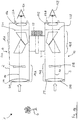
- Figure 1A shows a first schematic representation of the binoculars 1, which has a tubular first housing part 2 and a tubular second housing part 3.
- a first optical axis 10 runs through the first housing part 2.
- a second optical axis 11 runs through the second housing part 3.
- the first housing part 2 is connected to the second housing part 3 via an articulated bridge 4.
- the articulated bridge 4 has a first hinge part 5, which is molded onto the first housing part 2.
- the articulated bridge 4 has a second hinge part 6, which is arranged on the second housing part 3.
- the first hinge part 5 has a first receiving part 7 and a second receiving part 8, between which a third receiving part 9 of the second hinge part 6 is arranged.
- An axle bolt (not shown) runs through the first receiving part 7, the second receiving part 8 and the third receiving part 9, so that the relative position of the first housing part 2 and the second housing part 3 about an articulation axis 74 can be adjusted to one another.
- the first housing part 2 and the second housing part 3 it is possible to adjust the first housing part 2 and the second housing part 3 to the pupil distance of a user, so that on the one hand the first housing part 2 is arranged on one of the two eyes of the user and so that on the other hand the second housing part 3 the other of the user's two eyes is arranged.
- FIG. 1B shows a further illustration of the binoculars 1.
- the first housing part 2 has a first optical subsystem 12.
- the first optical subsystem 12 is provided with a first objective 14A, a first image stabilization unit 16A designed as a first prism system and a first eyepiece 17A.
- a first eye 15A of a user for observing an object O can be arranged on the first eyepiece 17A.
- the first optical axis 10 of the first optical subsystem 12 is laterally offset somewhat due to the first prism system 16A (first image stabilization unit 16A), so that the first optical axis 10 is stepped.
- the first lens 14A consists of a first front unit 51A and a first focusing unit 52A. Further embodiments of the first lens 14A provide a different number of individual lenses or cemented elements consisting of lenses. For the purpose of focusing the object O viewed through binoculars 1, either the first eyepiece 17A or the first focusing unit 52A can be displaced axially along the first optical axis 10. In a further embodiment, the first front unit 51A or even the entire first objective 14A is displaced along the first optical axis 10. In another embodiment the first front unit 51A and the first focusing unit 52A are shifted relative to each other.
- the second housing part 3 has a second optical subsystem 13.
- the second optical subsystem 13 is provided with a second objective 14B, with a second image stabilization unit 16B designed as a prism system and with a second eyepiece 17B.
- a second eye 15B of the user for observing the object O can be arranged on the second eyepiece 17B.
- the second optical axis 11 of the second optical subsystem 13 is laterally offset somewhat due to the second image stabilization unit 16B (prism system), so that the second optical axis 11 is formed in stages.
- the second lens 14B consists of a second front unit 51B and a second focusing unit 52B.
- Further embodiments of the second objective 14B provide a different number of individual lenses or cemented elements consisting of lenses.
- either the second eyepiece 17B or the second focusing unit 52B can be displaced axially along the second optical axis 11.
- the second front unit 51B or even the entire second objective 14B is displaced along the second optical axis 11.
- the second front unit 51B and the second focusing unit 52B are shifted relative to one another.
- the beam direction of the light rays incident in the optical subsystems 12, 13 is as follows: Object O - objective 14A, 14B - image stabilization unit (prism system) 16A, 16B - eyepiece 17A, 17B - eye 15A, 15B .
- a rotary knob 53 is arranged on the articulated bridge 4, with which the first focusing unit 52A and the second focusing unit 52B can be moved together along the two optical axes 10 and 11.
- the first lens 14A and the second lens 14B (or to adjust at least units of the first lens 14A and the second lens 14B) relative to one another.
- both the first lens 14A and the second lens 14B produce a real image that is upside down relative to the object O in question in an image plane assigned to the respective lens 14A, 14B.
- the first prism system 16A assigned to the first lens 14A (first image stabilization unit) and the second prism system 16B assigned to the second lens 14B (second image stabilization unit) are used for image erection.
- the upside-down image is thus erected again and imaged in a new image plane, the left intermediate image plane 23A or the right intermediate image plane 23B.
- the first prism system 16A (first image stabilization unit) and the second prism system 16B (second image stabilization unit) can be constructed as an Abbe-König prism system, Schmidt-Pechan prism system, Uppendahl prism system, Porro prism system or another prism system variant.
- a first field diaphragm is sharply delimiting the field of view.
- a second field diaphragm sharply delimiting the field of view can be arranged, for example, in the right intermediate image plane 23B.
- the first eyepiece 17A is used to image the left intermediate image plane 23A at any distance, e.g. to infinity or another distance. Furthermore, the second eyepiece 17B is used to extend the image of the right intermediate image plane 23B at an arbitrary distance, e.g. to infinity or another distance.
- the first aperture diaphragm 54A of the first optical subsystem 12 and the second aperture diaphragm 54B of the second optical subsystem 13 can either be made by mounting an optical element of the corresponding optical subsystem 12, 13, usually by mounting the lenses of the first front unit 51A or the second Front unit 51B, or be formed by a separate panel. It can be imaged in the beam direction by the corresponding optical subsystem 12 or 13 in a plane that lies behind the corresponding eyepiece 17A or 17B in the beam direction and is typically 5 to 25 mm away from it. This level is called the exit pupil level.
- an extendable, rotatable or foldable first eyecup 55A can be provided on the first eyepiece 17A and an extendable, rotatable or foldable second eyecup 55B can be provided on the second eyepiece 17B.
- Figure 2A shows a schematic representation of the first optical subsystem 12, which is arranged in the first housing part 2.
- the second optical subsystem 13 arranged in the second housing part 3 has an identical structure to the first optical subsystem 12.
- the following explanations with regard to the first optical subsystem 12 thus also apply to the second optical subsystem 13.
- the first objective 14A, the first image stabilization unit 16A and the first eyepiece 17A are arranged along the first optical axis 10 from the object O in the direction of the user's first eye 15A.
- the first image stabilization unit 16A is designed as a prism reversal system.
- the first image stabilization unit 16A is designed as a lens inversion system.
- the second optical subsystem 13 has an identical structure to the first optical subsystem 12.
- the second prism system is designed as a second image stabilization unit 16B.
- Figure 2B shows a further schematic representation of the binoculars 1.
- Figure 2B is based on the Figure 1B .
- the same components are provided with the same reference symbols.
- Figure 2B now also shows the movement devices for the first image stabilization unit 16A and the second image stabilization unit 16B.
- the first image stabilization unit 16A is arranged in a first gimbal 60A.
- the second image stabilization unit 16B is arranged in a second cardanic mechanism 60B.
- the arrangement of the two image stabilization units 16A and 16B is shown in FIG Figure 2C presented in more detail.
- the first cardan mechanism 60A has a first outer suspension 61A, which is arranged on the first housing part 2 via a first axis 18A.
- the first outer suspension 61A is rotatable about the first axis 18A arranged.
- the first cardan mechanism 60A has a first inner suspension 62A, which is rotatably arranged on the first outer suspension 61A via a second axis 19A.
- the first inner suspension 62A is rotated about the second axis 19A via a first drive unit 24A.
- a second drive unit 24B is provided, by means of which the first outer suspension 61A is rotated about the first axis 18A.
- Figure 2E shows the above in an enlarged view.
- the first image stabilization unit 16A is held on the first inner suspension 62A by means of clamp holders 71.
- the second image stabilization unit 16B is arranged on the second cardanic mechanism 60B.
- the second gimbal 60B has a second outer suspension 61B, which is arranged on the second housing part 3 via a third axis 18B.
- the second outer suspension 61B is rotatably arranged about the third axis 18B.
- the second gimbal 60B has a second inner suspension 62B, which is rotatably arranged on the second outer suspension 61B via a fourth axis 19B.
- the second inner suspension 62B is rotated about the third axis 19B via a third drive unit 24C.
- a fourth drive unit 24D is also provided, by means of which the second outer suspension 61B is rotated about the third axis 18B.
- the first image stabilization unit 16A is arranged by means of the first cardan mechanism 60A in such a way that it is rotatably mounted about two axes arranged at right angles to one another, namely about the first axis 18A and about the second axis 19A, which projects into the sheet plane.
- the first axis 18A and the second axis 19A intersect at a first intersection 20A.
- the first intersection 20A is arranged differently from a first optically neutral point on the first optical axis 10. In this regard, reference is made to the statements already made above.
- the first image stabilization unit 16A has a first entry surface 21 and a first exit surface 22.
- the first exit surface 22 is arranged in a range of 1 mm to 20 mm at a distance from the left intermediate image plane 23A.
- the first exit surface 22 is arranged in a range of 2 mm to 15 mm at a distance from the left intermediate image plane 23A.
- the first exit surface 22 is arranged at a distance of 3 mm to 12 mm from the left intermediate image plane 23A.
- the quality of the image which is generated by the first optical subsystem 12 is improved because of manufacturing tolerances which occur during the production of the first image stabilization unit 16A have to be accepted, no longer have a strong impact on the generated image.
- the extent and volume of the first image stabilization unit 16A can be smaller compared to the prior art due to the beam path. This means that the mass of the first image stabilization unit 16A can be less than in the prior art.
- the moment of inertia of the first image stabilization unit 16A is reduced in such a way that the adjustment of the first image stabilization unit 16A can be effected with a relatively small force.
- the smaller volume, the smaller expansion and the possibility of using drive units which provide a low force for adjusting the first image stabilization unit 16A enable the first housing part 2 to be made smaller than the housing parts used in the prior art. This provides a shapely housing which reminds the user of normal binoculars and which gives an aesthetically more attractive impression than the known prior art. This creates a beautiful aesthetic impression for many users.
- the binoculars 1 in two tubes (namely a first tube corresponding to the first housing part 2 and a second tube corresponding to the second housing part 3), which corresponds to the division of a pair of binoculars which is customary for a user and what is essential for the adjustment of the eye relief simplified.
- the use of two image stabilization units namely the first image stabilization unit 16A in the first housing part 2 and the second image stabilization unit 16B in the second housing part 3) enables a significant reduction in the moment of inertia compared to the prior art of the two image stabilization units so that piezo actuators can be used.
- FIGS. 3A - 3C show schematic representations of a drive unit 24 in the form of a piezo bending actuator, an actuator being understood to be an actuating element which can generate a force or a movement. In the literature, such an actuator is often referred to as an actuator.
- the first drive unit 24A, the second drive unit 24B, the third drive unit 24C and the fourth drive unit 24D are constructed identically to the drive unit 24, for example.
- the Figure 3A shows a schematic representation of the drive unit 24.
- the drive unit 24 has a first piezoceramic 25 and a second piezoceramic 26 which are arranged one on top of the other. Both the first piezoceramic 25 and the second piezoceramic 26 can be supplied with a voltage via a voltage unit 27. In other words, a first voltage is applied to the first piezoceramic 25 and a second voltage is applied to the second piezoceramic 26.
- the two aforementioned voltages on the first piezoceramic 25 and on the second piezoceramic 26 are switched with opposite poles, so that, for example, the first piezoceramic 25 expands and, on the other hand, the second piezoceramic 26 contracts.
- the overall arrangement of the first piezoceramic 25 and the second piezoceramic 26 bends, as in FIGS Figures 3B and 3C shown.
- FIGS. 4A - 4F show schematic representations of arrangements of the drive unit 24 according to the Figures 3A - 3C on the first image stabilization unit 16A or the second image stabilization unit 16B.
- the drive unit 24 (ie the piezo bending actuator) has an arrangement formed from the first piezoceramic and the second piezoceramic.
- This arrangement has a first end and a second end.
- the first end of the arrangement is on the first housing part 2 or on the second housing part 3 fixedly arranged by means of a socket 28.
- the second end of the arrangement is connected by means of a floating bearing 29 to the first gimbal 60A of the first image stabilization unit 16A or to the second gimbal 60B of the second image stabilization unit 16B. More specifically, the second end of the assembly is movably located at a point of the first outer suspension 61A or the second outer suspension 61B.
- the point is not only to be understood in the mathematical sense, but can also be a surface or a volume.
- the point forms a lever arm 30 with the intended axis of rotation (for example, the first axis or the second axis).
- the arrangement has a longitudinal axis 31 which is arranged parallel to the first optical axis 10 or to the second optical axis 11.
- the invention is not restricted to the exemplary embodiment of an arrangement of the drive unit 24 described here. Rather, any suitable arrangement of the drive unit 24 on the first gimbal 60A of the first image stabilization unit 16A or the second gimbal 60B of the second image stabilization unit 16B can be used, in particular in the form of the exemplary embodiments described in more detail below.
- One of these exemplary embodiments includes, in particular, that it can alternatively be provided that the drive unit 24 with one of the ends of the arrangement is firmly attached to the first gimbal 60A of the first image stabilization unit 16A or to the second gimbal 60B of the second image stabilization unit 16B and with the other of the ends of the Arrangement is arranged loosely on the first housing part 2 or on the second housing part 3.
- the floating bearing 29 is designed in such a way that the drive unit 24 can move in a first direction (arrow direction A) or in a second direction (arrow direction B).
- the end of the arrangement of the drive unit 24 arranged on the floating bearing 29 should be designed in such a way that the drive unit 24 has as little play as possible on the first cardanic 60A of the first image stabilization unit 16A or the second cardanic 60B of the second image stabilization unit 16B. In this way, a particularly precise control of the movement of the first image stabilization unit 16A or the second image stabilization unit 16B is possible.
- the embodiment according to the Figure 4B is based on the exemplary embodiment according to FIG Figure 4A .
- the same components are therefore with the same reference numerals Mistake.
- the embodiment according to the Figure 4B differs from the embodiment of the Figure 4A only in that the longitudinal axis 31 of the drive unit 24 is arranged perpendicular to the first optical axis 10 or the second optical axis 11.
- the embodiment according to the Figure 4C is based on the embodiment of Figure 4A .
- the same components are therefore provided with the same reference numerals.
- the embodiment of Figure 4A shows the embodiment of Figure 4C the difference that the longitudinal axis 31 of the drive unit 24 runs along the first optical axis 10 or the second optical axis 11.
- the further embodiment according to the Figure 4D is based on the embodiment of Figure 4C .
- the same components are therefore provided with the same reference numerals.
- the embodiment of the Figure 4D differs from the embodiment of Figure 4C only in that the drive unit 24 is arranged laterally between the first housing part 2 and the first outer suspension 61A on the first image stabilization unit 16A or between the second housing part 3 and the second outer suspension 61B on the second image stabilization unit 16B such that the first image stabilization unit 16A or the second image stabilization unit 16B covers the drive unit 24.
- FIG Figure 4E A further exemplary embodiment of a possible fastening of the drive unit 24 to the first image stabilization unit 16A or the second image stabilization unit 16B is shown in FIG Figure 4E shown.
- the embodiment according to the Figure 4E is based on the exemplary embodiment according to FIG Figure 4A .
- the same components are therefore provided with the same reference numerals.
- the embodiment according to the Figure 4E differs from the embodiment of the Figure 4A a drive unit 24, the longitudinal axis 31 of which is arranged on the one hand parallel to the second axis 19A or to the fourth axis 19B, which is also the axis of rotation.
- the longitudinal axis 31 is arranged perpendicular to the first optical axis 10 or to the second optical axis 11.
- FIG. 4F Another embodiment shows the Figure 4F .
- the embodiment of the Figure 4F is also based on the embodiment of Figure 4A . Same Components are therefore provided with the same reference symbols.
- Another end of the drive unit 24 is arranged in a floating bearing 29, which is arranged on the first housing part 2 or the second housing part 3.
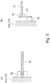
- FIGS. 5A and 5B show schematic representations of arrangements of the drive unit 24 on the first image stabilization unit 16A or on the second image stabilization unit 16B. So shows Figure 5A That the first end of the drive unit is arranged in the movable bearing 29 24, which is formed C-shaped and has the arrangement of the two above-mentioned piezoelectric ceramics.
- the floating bearing 29 is arranged on the first outer suspension 61A of the image stabilization unit 16A or on the second outer suspension 61B of the second image stabilization unit 16B.
- the Figure 5B shows the first outer suspension 61A of the first image stabilization unit 16A or the second outer suspension 61B of the second image stabilization unit 16B, on which a nozzle 35 is arranged.
- a spring plate 34 on which a clamping unit 33 is fastened, is in turn arranged on the connecting piece 35.
- the first end of the drive unit 24 is fixedly arranged on the clamping unit 33.
- the drive unit 24 assumes a specific position in space and no longer moves.
- this particular position is the position in which correct binocular adjustment is guaranteed.
- the drive unit 24 can therefore be used as a holding device which holds the first gimbals 60A of the first image stabilization unit 16A or the second gimbals 60B of the second image stabilization unit 16B.
- the first image stabilization unit 16A or the second image stabilization unit 16B can therefore no longer move in space.
- the first image stabilization unit 16A and / or the second Image stabilization unit 16B is / are locked and therefore cannot be damaged if the binoculars 1 are not used.
- the invention is not restricted to the described drive unit 24 in the form of a piezo bending actuator. Rather, any type of drive units can be used which are suitable for carrying out a movement of the first image stabilization unit 16A or the second image stabilization unit 16B. This also includes drive units that do not work on the basis of piezo technology. Further suitable drive units based on piezo technology are, for example, a piezo linear actuator, a piezo traveling wave actuator or an ultrasonic motor. Piezo actuators are particularly well suited because they have a high level of self-locking, so that additional locking of the first image stabilization unit 16A or the second image stabilization unit 16B can be dispensed with. This has already been explained above. Furthermore, their power consumption is very low, so that the lifespan of batteries used for power supply is longer.
- the movement of the first image stabilization unit 16A or the second image stabilization unit 16B and thus also the position of the first image stabilization unit 16A or the second image stabilization unit 16B are monitored with at least one sensor.
- a first sensor for movement relative to the first axis 18A and a second sensor for movement relative to the second axis 19A are provided.
- a third sensor for movement relative to third axis 18B and a fourth sensor for movement relative to fourth axis 19B are provided.
- a Hall sensor is used as the sensor.
- the invention is not restricted to this type of sensor. Rather, any suitable type of sensor and also any suitable number of sensors can be used.
- the aforementioned sensor serves to improve the quality of the image stabilization. It is explicitly pointed out that the invention is not restricted to the use of such a sensor. Rather, no sensor can be provided in the invention.
- Figure 6 shows a schematic representation of a block diagram of control and measuring units for image stabilization in the optical system in the form of Binoculars 1.
- the first gimbals 60A of the first image stabilization unit 16A, the first drive unit 24A and the second drive unit 24B, which are arranged in the first housing part 2, on the one hand, and the second gimbals 60B of the second image stabilization unit 16B, the third drive unit 24C and the fourth drive unit 24D, which are arranged in the second housing part 3, on the other hand are connected to a control and monitoring unit 37 (for example a microcontroller).
- the control and monitoring unit 37 is in turn connected to a first angular velocity detector 38 and to a second angular velocity detector 39.
- the first angular velocity detector 38 serves to detect movements of the binoculars 1 and is arranged in the first housing part 2.
- the second angular velocity detector 39 also serves to detect movements of the binoculars 1 and is arranged in the first housing part 2.
- the aforementioned movements are, for example, rotary and / or translatory tremors.
- the control and monitoring unit 37 is connected to an articulated bridge sensor 40.
- the use of the articulated bridge sensor 40 has the following background.
- the relative position of the axes of rotation (namely, on the one hand the first axis 18A and the second axis 19A of the first image stabilization unit 16A and on the other hand the third axis 18B and the fourth axis 19B of the second image stabilization unit 16B) changes when the interpupillary distance is set via the articulation bridge 4.
- the articulated bridge sensor 40 now determines a so-called articulated bridge angle a between a first hinge part axis 72 of the first hinge part 5 and a second hinge part axis 73 of the second hinge part 6, the first hinge part axis 72 and the second hinge part axis 73 having a common intersection with the hinge axis 74 (cf. Figures 2C and 2D ).
- the articulated bridge angle a in Figure 2C in which the first axis 18A and the third axis 18B are arranged parallel to one another, are already 175 °.
- the position (rotation position) of the first image stabilization unit 16A and the position (rotation position) of the second image stabilization unit 16B are set, for example, as described below.
- an angular velocity due to a movement of the binoculars 1 relative to the observed environment is detected.
- the first angular velocity detector 38 and the second angular velocity detector 39 provide angular velocity signals dependent on the movement.
- the angular velocity signals are used in the control and monitoring unit 37 to determine rotation angles around the rotation axes of the first image stabilization unit 16A (for example the first axis 18A and the second axis 19A) and rotation angles about the rotation axes of the second image stabilization unit 16B (for example the third axis 18B and the fourth axis) 19B).
- the angles of rotation determined in this way are now converted into first correction angles, by which the first image stabilization unit 16A must be rotated in order to be positioned in space.
- the rotation angles are used to calculate a second correction angle by which the second image stabilization unit 16B has to be rotated in order to be “fixed” in space.
- the point of intersection of the axes of rotation does not match the optically neutral point of the binoculars 1.
- the relative position of the measuring axes of the two angular velocity detectors 38 and 39 and the axes of rotation of the first image stabilization unit 16A and the second should Image stabilization unit 16B must be observed.
- the appropriate correction angle is obtained by a suitable transformation.
- the position of the measurement axes of the two angular velocity detectors 38 and 39 corresponds to the position of the first axis 18A and the second axis 19A of the first image stabilization unit 16A.
- the angle of rotation of the first image stabilization unit 16A can then be transformed into the angle of rotation of the second image stabilization unit 16B by means of the determined articulation bridge angle a.
- the exemplary embodiment shown here has a voltage supply unit 63 which is connected to the first drive unit 24A, the second drive unit 24B, the third drive unit 24C and the fourth drive unit 24D for supplying the aforementioned drive units with voltage.
- the voltage supply unit 63 is designed, for example, as a (rechargeable) battery, the voltage of which is still present is measured with a voltage measuring unit 64.
- the voltage measuring unit is connected to the control and monitoring unit 37.
- the Figure 7 is a block diagram of another embodiment of control and measurement units based on the embodiment of FIG Figure 6 based. The same components are therefore provided with the same reference numerals.
- the embodiment according to the Figure 6 has the embodiment according to the Figure 7 two control and monitoring units, namely a first control and monitoring unit 37A and a second control and monitoring unit 37B.
- the first control and monitoring unit 37A is connected to the first angular velocity detector 38, to the first gimbal 60A of the first image stabilization unit 16A, to the first drive unit 24A and to the second drive unit 24B.
- the first control and monitoring unit 37A is arranged, for example, in the first housing part 2.
- the second control and monitoring unit 37B is connected to the second angular velocity detector 39, to the second gimbal 60B of the second image stabilization unit 16B, to the third drive unit 24C and to the fourth drive unit 24D.
- the second control and monitoring unit 37B is arranged, for example, in the second housing part 3.
- the articulated bridge sensor 40 is connected to both the first control and monitoring unit 37A and the second control and monitoring unit 37B.
- the first angular velocity detector 38 is connected to the second control and monitoring unit 37B connected.
- the second angular velocity detector 39 is connected to the first control and monitoring unit 37A.
- This exemplary embodiment accordingly uses a separate control and monitoring unit for the first optical subsystem 12 in the first housing part 2 and for the second optical subsystem 13 in the second housing part 3, although the angular velocity detectors 38, 39 for detecting movements of binoculars 1 are shared.
- the voltage measuring unit 64 is connected both to the first control and monitoring unit 37A and to the second control and monitoring unit 37B.
- Figure 8 shows a block diagram of another embodiment of an arrangement of control and measuring units.
- the embodiment of the Figure 8 is based on the embodiment of Figure 6 . Identical units are provided with the same reference symbols. In this exemplary embodiment, it is provided that a separate control unit is provided for each of the two housing parts 2 and 3 mentioned above.
- the first image stabilization unit 16A, the first cardanic mechanism 60A, the first drive unit 24A, the second drive unit 24B and the first control and monitoring unit 37A are arranged in the first housing part 2.
- the first control and monitoring unit 37A is connected to the first angular velocity detector 38 and the second angular velocity detector 39, which are likewise arranged in the first housing part 2.
- the second image stabilization unit 16B, the second cardanic mechanism 60B, the third drive unit 24C, the fourth drive unit 24D and the second control unit 37B are arranged in the second housing part 3. Furthermore, a third angular velocity detector 41 and a fourth angular velocity detector 42 are arranged in the second housing part 3 and determine the movements of the binoculars 1.
- the voltage measuring unit 64 is connected both to the first control and monitoring unit 37A and to the second control and monitoring unit 37B.
- At least one of the above and / or following angular velocity detectors is replaced by an acceleration detector.
- the speed is also obtained.
- FIG. 9 is based on the Figure 1B .
- the same components are provided with the same reference symbols.
- FIG Figure 1B shows the embodiment of Figure 9 Sensors 65 to 70, the function of which is explained below. Another function of the voltage measuring unit 64 is also explained.
- the voltage measuring unit 64 and the sensors 65 to 70 serve to control and limit the energy consumption of the aforementioned drive units 24A to 24D in such a way that only the energy actually required in a given situation is consumed.
- Image stabilization by moving the first image stabilization unit 16A and the second image stabilization unit 16B should only take place, for example, when a user actually uses the binoculars 1.
- the binoculars 1 it is provided with the binoculars 1 that the scope and the quality of the image stabilization are adapted to the available energy.
- the binoculars 1 provide for the quality of the image stabilization to be adapted to the observation situation. For example, very high quality image stabilization is not absolutely necessary when the binoculars 1 are used in the dark or when the magnification is very small.
- the voltage measuring unit 64 already described above always measures the voltage of the voltage supply unit 63 that is still available.
- the voltage supply unit 63 can only provide a small amount of energy, the maximum rotation angle at which the first image stabilization unit 16A and / or the second image stabilization unit 16B are rotated is limited, for example. As a result, the movements of the two aforementioned image stabilization units 16A and 16B become shorter and / or slower. This reduces energy consumption.
- the voltage supply unit 63 can only provide a small amount of energy - low-frequency and / or high-frequency components of a Movement of the binoculars 1 (for example a trembling movement) are no longer taken into account in the image stabilization.
- Low-frequency parts of a movement have hardly any effect on a detail recognizability.
- the low-frequency components are relatively large movements, so that the power consumption of the aforementioned drive units 24A to 24D is reduced if the low-frequency components are no longer taken into account in the image stabilization.
- the energy consumption drops, even if high-frequency components are not used for image stabilization.
- the amplitude of a movement of at least one of the two aforementioned image stabilization units 16A and 16B is generally reduced if the voltage supply unit 63 can only provide a certain amount of energy. Additionally or alternatively, it is provided that the speed at which at least one of the two image stabilization units 16A and 16B is moved is limited to a maximum speed. This reduces the power consumption of the corresponding drive units 24A to 24D of the respective image stabilization units 16A and 16B.
- the binoculars 1 have a brightness sensor 65 arranged on the articulated bridge 4 for determining the ambient brightness.
- the perception of a user of the binoculars 1 is no longer very fast. Movements of the binoculars 1 are no longer perceived in the dark in such a way that they are perceived as disturbing.
- the control and monitoring unit 37, the first control and monitoring unit 37A or the second control and monitoring unit 37B therefore switches to a night mode.
- the image stabilization is switched off completely.
- the binoculars 1 also have a position sensor 66 arranged on the articulated bridge 4 for determining an inclination of the binoculars 1.
- the position sensor 66 makes it possible to determine the position of the optical axes 10 and 11 of the binoculars 1 in space. If an excessively large deviation (for example a deviation of the optical axes 10 and 11 by 70 ° to 100 ° to the horizontal) is determined, then it can be assumed that the binoculars 1 are not used. In this case, the control and control unit 37, the first control and control unit 37A or the second control and control unit 37B therefore switches off the image stabilization of the binoculars 1.
- the binoculars 1 is provided with a sensor 67 for detecting a monocular use of the binoculars 1.
- This sensor 67 is arranged, for example, on the second housing part 3 in the region of the second objective 16B.
- the invention is not restricted to this type of arrangement. Rather, the sensor 67 can be arranged at any location of the binoculars 1 that is suitable for this. If a so-called optical booster is arranged on the second housing part 3, this is detected by means of the sensor 67. In this case, the control and control unit 37, the first control and control unit 37A or the second control and control unit 37B therefore switches off the image stabilization of the binoculars 1.
- the binoculars 1 furthermore each have an eye sensor 68 in the area of the first eyepiece 17A and the second eyepiece 17B for detecting the eyes 15A, 15B of a user.
- an eye sensor 68 for example, a photo sensor is suitable for measuring the light on the first eyepiece 17A and / or on the second eyepiece 17B.
- Still further exemplary embodiments provide for a capacitance measurement. If there is no eye on the first eyepiece 17A and the second eyepiece 17B, the control and monitoring unit 37, the first control and monitoring unit 37A or the second control and monitoring unit 37B therefore switches off the image stabilization of the binoculars 1.
- a protective cap sensor 69 is arranged on the binoculars in the area of the first objective 14A, the second objective 14B, the first eyepiece 17A and the second eyepiece 17B, which serves to detect an arrangement of a lens protective cap and / or eyepiece protective cap. If a protective cap is arranged on the first lens 14A, the second lens 14B, the first eyepiece 17A and / or the second eyepiece 17B, it can be assumed that the binoculars 1 are not used.
- the control and monitoring unit 37, the first control and monitoring unit 37A or the second control and monitoring unit 37B then switches off the image stabilization of the binoculars 1.
- a hand sensor 70 is arranged on both the first housing part 2 and the second housing part 3 of the binoculars 1.
- the hand sensors 70 serve to identify an arrangement of a hand of a user on the binoculars 1.
- a capacitive sensor capacitive measurement
- a photo sensor or a pressure sensor is used as the hand sensor 70. If it is recognized that no hand is touching the binoculars 1, then it can be assumed that the binoculars 1 are not being used.
- the control and monitoring unit 37, the first control and monitoring unit 37A or the second control and monitoring unit 37B then switches off the image stabilization of the binoculars 1.
- the articulated bridge sensor 40 can also be used to optimize energy consumption.
- the buckling sensor 40 is used to determine whether there is a minimum buckling angle a of the buckling 4. If the minimum buckling bridge angle a is set, it can be assumed that the binoculars 1 are being transported.
- the control and monitoring unit 37, the first control and monitoring unit 37A or the second control and monitoring unit 37B then switches off the image stabilization of the binoculars 1.
Landscapes
- Physics & Mathematics (AREA)
- General Physics & Mathematics (AREA)
- Optics & Photonics (AREA)
- Engineering & Computer Science (AREA)
- Multimedia (AREA)
- Signal Processing (AREA)
- Astronomy & Astrophysics (AREA)
- Adjustment Of Camera Lenses (AREA)
- Telescopes (AREA)
- Studio Devices (AREA)
- Lenses (AREA)
Claims (16)
- Système optique (1) destiné à représenter un objet (0), ledit système comprenant- un premier objectif (14A),- une première unité de stabilisation d'image (16A),- un premier plan d'image (23A),- lorsque l'on regarde depuis le premier objectif (14A) en direction du premier plan d'image (23A), tout d'abord le premier objectif (14A), puis la première unité de stabilisation d'image (16A) et ensuite le premier plan d'image (23A) étant disposés le long d'un premier axe optique (10),- la première unité de stabilisation d'image (16A) comportant une première surface d'entrée (21) et une première surface de sortie (23),- la première surface d'entrée (21) étant dirigée vers le premier objectif (14A),- la première surface de sortie (22) étant dirigée vers le premier plan image (23A),- le système optique (1) comportant un premier boîtier (2), le premier objectif (14A), la première unité de stabilisation d'image (16A) et le premier plan d'image (23A) étant disposés dans le premier boîtier (2),- le système optique (1) comportant un deuxième objectif (14B), une deuxième unité de stabilisation d'image (16B) et un deuxième plan d'image (23B),- lorsque l'on regarde depuis le deuxième objectif (14B) en direction du deuxième plan image (23B), tout d'abord le deuxième objectif (23B), puis la deuxième unité de stabilisation d'image (16B) et ensuite le deuxième plan d'image (23B) étant disposés le long d'un deuxième axe optique (11),- la deuxième unité de stabilisation d'image (16B) comportant une deuxième surface d'entrée et une deuxième surface de sortie,- la deuxième surface d'entrée étant dirigée vers le deuxième objectif (14B),- la deuxième surface de sortie étant dirigée vers le deuxième plan image (23B),- le système optique (1) comportant un deuxième boîtier (3), le deuxième objectif (14B), la deuxième unité de stabilisation d'image (16B) et le deuxième plan d'image (23B) étant disposés dans le deuxième boîtier (3),- le premier boîtier (2) étant relié au deuxième boîtier (3) par le biais d'au moins un pont articulé (4),- le pont articulé (4) comportant une première partie d'articulation (5) disposée au niveau du premier boîtier (2), et- le pont articulé (4) comportant une deuxième partie d'articulation (6) disposée au niveau du deuxième boîtier (2),
caractérisé en ce que
la première surface de sortie (22) est disposée dans une zone distante de 1 mm à 20 mm du premier plan d'image (23A), la deuxième surface de sortie est disposée dans une zone distante de 1 mm à 20 mm du deuxième plan d'image (23B) et la première unité de stabilisation d'image (16A) est disposée à cardan dans le premier boîtier (2). - Système optique (1) selon la revendication 1, caractérisé en ce que le système optique (1) présente l'une des caractéristiques suivantes :- la première surface de sortie (22) est disposée dans une zone distante de 2 mm à 15 mm du premier plan d'image (23A), ou- la première surface de sortie (22) est disposée dans une zone distante de 3 mm à 12 mm du premier plan d'image (23A).
- Système optique (1) selon la revendication 1 ou 2, caractérisé en ce que la première unité de stabilisation d'image (16A) est conçue pour être mobile.
- Système optique (1) selon l'une des revendications précédentes, caractérisé en ce que le système optique (1) présente l'une des caractéristiques suivantes :- une première unité d'acquisition d'image est disposée dans le premier plan image (23A),- une première unité d'acquisition d'image est disposée dans le premier plan image (23A), la première unité d'acquisition d'image étant conçue comme un capteur à base de semi-conducteur, ou- le système optique (1) comporte un premier oculaire (17A), le premier plan d'image (23A) étant disposé en premier et le premier oculaire (17A) étant disposé ensuite lorsque l'on regarde depuis le premier objectif (14A) en direction du premier plan d'image (23A).
- Système optique (1) selon la revendication 1, caractérisé en ce que- le système optique (1) comporte un premier oculaire (17A), le premier plan d'image (23A) étant disposé en premier et le premier oculaire (17A) étant disposé ensuite lorsque l'on regarde depuis le premier objectif (14A) en direction du premier plan d'image (23A), et- le premier oculaire (17A) est disposé dans le premier boîtier (2).
- Système optique (1) selon l'une des revendications précédentes, caractérisé en ce que la deuxième unité de stabilisation d'image (16B) est conçue pour être mobile.
- Système optique (1) selon l'une des revendications précédentes, caractérisé en ce que le système optique (1) présente l'une des caractéristiques suivantes :- une deuxième unité d'acquisition d'image est disposée dans le deuxième plan image (23B),- une deuxième unité d'acquisition d'image, qui est conçue comme un capteur à base de semi-conducteur, est disposée dans le deuxième plan d'image (23B), ou- le système optique (1) comporte un deuxième oculaire (17B), le deuxième plan d'image (23B) étant disposé en premier et le deuxième oculaire (17B) étant disposé ensuite lorsque l'on regarde depuis le deuxième objectif (14B) en direction du deuxième plan d'image (23B).
- Système optique (1) selon la revendication 1, caractérisé en ce que- le système optique (1) comporte un deuxième oculaire (17B), le deuxième plan d'image (23B) étant disposé en premier et le deuxième oculaire (17B) étant disposé ensuite lorsque l'on regarde depuis le deuxième objectif (14B) en direction du deuxième plan d'image (23B), et- le deuxième oculaire (17B) est disposé dans le deuxième boîtier (3).
- Système optique (1) selon l'une des revendications précédentes, caractérisé en ce que le système optique (1) présente l'une des caractéristiques suivantes :- la première unité de stabilisation d'image (16A) est conçue comme un premier système d'inversion,- la première unité de stabilisation d'image (16A) est conçue comme un premier système d'inversion à prismes,- la première unité de stabilisation d'image (16A) est conçue comme un premier système d'inversion à lentilles,- la deuxième unité de stabilisation d'image (16B) est conçue comme un deuxième système d'inversion,- la deuxième unité de stabilisation d'image (16B) est conçue comme un deuxième système d'inversion à prismes, ou- la deuxième unité de stabilisation d'image (16B) est conçue comme un deuxième système d'inversion à lentilles.
- Système optique (1) selon l'une des revendications précédentes, caractérisé en ce que le système optique (1) présente l'une des caractéristiques suivantes :- la première unité de stabilisation d'image (16A) est disposée dans le premier boîtier (2) de manière à pouvoir tourner sur un premier axe (18A) et sur un deuxième axe (19A), le premier axe (18A) et le deuxième axe (19A) se coupant en un premier point d'intersection (20) qui est différent d'un premier point optique neutre sur le premier axe optique (10) et qui est disposé sur le premier axe optique (10),- au moins une première unité d'entraînement (24, 24A, 24B) destinée à déplacer la première unité de stabilisation d'image (16A),- au moins une première unité d'entraînement (24, 24A, 24B) destinée à déplacer la première unité de stabilisation d'image (16A), la première unité d'entraînement (24, 24A, 24B) comportant au moins une première céramique piézoélectrique,- au moins une première unité d'entraînement (24, 24A, 24B) destinée à déplacer la première unité de stabilisation d'image (16A), la première unité d'entraînement (24, 24A, 24B) comportant au moins un premier actionneur piézoélectrique,- au moins une première unité d'entraînement (24, 24A, 24B) destinée à déplacer la première unité de stabilisation d'image (16A), la première unité d'entraînement (24, 24A, 24B) comportant au moins un premier actionneur de flexion piézoélectrique,- au moins une première unité d'entraînement (24, 24A, 24B) destinée à déplacer la première unité de stabilisation d'image (16A) et au moins une première unité de commande (37A) destinée à commander la première unité d'entraînement (24, 24A, 24B),- la deuxième unité de stabilisation d'image (16B) est disposée à cardan dans le deuxième boîtier (3),- la deuxième unité de stabilisation d'image (16B) est disposée dans le deuxième boîtier (3) de manière à pouvoir tourner sur un troisième axe (18B) et sur un quatrième axe (19B), le troisième axe (18B) et le quatrième axe (19B) se coupant en un deuxième point d'intersection qui est différent d'un deuxième point neutre optique sur le deuxième axe optique (11) et qui est disposé sur le deuxième axe optique (11),- au moins une deuxième unité d'entraînement (24, 24C, 24D) destinée à déplacer la deuxième unité de stabilisation d'image (16B),- au moins une deuxième unité d'entraînement (24, 24C, 24D) destinée à déplacer la deuxième unité de stabilisation d'image (16B), la deuxième unité d'entraînement (24, 24C, 24D) comportant au moins une deuxième céramique piézoélectrique,- au moins une deuxième unité d'entraînement (24, 24C, 24D) destinée à déplacer la deuxième unité de stabilisation d'image (16B), la deuxième unité d'entraînement (24, 24C, 24D) comportant au moins un deuxième actionneur piézoélectrique,- au moins une deuxième unité d'entraînement (24, 24C, 24D) destinée à déplacer la deuxième unité de stabilisation d'image (16B), la deuxième unité d'entraînement (24, 24C, 24D) comportant au moins un deuxième actionneur de flexion piézoélectrique, ou- au moins une deuxième unité d'entraînement (24, 24C, 24D) destinée à déplacer la deuxième unité de stabilisation d'image (16B) et au moins une deuxième unité de commande (37B) destinée à commander la deuxième unité d'entraînement (24, 24C, 24D).
- Système optique (1) selon les revendications 3 et 6, caractérisé en ce que le système optique (1) comporte au moins une unité de commande (37) destinée à commander une première unité d'entraînement (24, 24A, 24B) destinée à déplacer la première unité de stabilisation d'image (16A) et une deuxième unité d'entraînement (24, 24C, 24D) destinée à déplacer la deuxième unité de stabilisation d'image (16B).
- Système optique (1) selon l'une des revendications précédentes, caractérisé en ce que le système optique (1) présente l'une des caractéristiques suivantes :- au moins un détecteur de mouvement (38, 39) destiné à déterminer un mouvement du système optique (1),- au moins un premier détecteur de mouvement (38) destiné à déterminer un mouvement du système optique (1) et au moins un deuxième détecteur de mouvement (39) destiné à déterminer un mouvement du système optique (1),- au moins un détecteur de stabilisation destiné à déterminer un mouvement de la première unité de stabilisation d'image (16A) et/ou de la deuxième unité de stabilisation d'image (16B), ou- au moins un premier détecteur de stabilisation destiné à déterminer un mouvement de la première unité de stabilisation d'image (16A) et au moins un deuxième détecteur de stabilisation destiné à déterminer un mouvement de la deuxième unité de stabilisation d'image (16B) .
- Système optique (1) selon la revendication 1, caractérisé en ce que le système optique (1) comporte au moins l'une des caractéristiques suivantes :- le premier boîtier (2) est conçu comme un tube, ou- le deuxième boîtier (3) est conçu comme un tube.
- Système optique (1) selon la revendication 10, caractérisé en ce que le système optique (1) comporte au moins un dispositif de mesure (64), destiné à mesurer la tension d'une unité d'alimentation en tension (63) destinée à alimenter la première unité d'entraînement (24, 24A, 24B) et/ou la deuxième unité d'entraînement (24, 24C, 24D), et au moins une unité de commande (37, 37A, 37B), l'unité de commande (37, 37A, 37B) étant conçue pour l'une au moins des propriétés suivantes :- limitation d'un angle de rotation de la première unité de stabilisation d'image (16A) et/ou de la deuxième unité de stabilisation d'image (16B) ;- déplacement de la première unité de stabilisation d'image (16A) et/ou de la deuxième unité de stabilisation d'image (16B) lorsqu'une première fréquence limite est dépassée vers le haut et/ou lorsqu'une deuxième fréquence limite est dépassée vers le bas ; ou- limitation d'une vitesse de déplacement de la première unité de stabilisation d'image (16A) et/ou de la deuxième unité de stabilisation d'image (16B).
- Système optique (1) selon l'une des revendications précédentes, caractérisé en ce que le système optique (1) présente l'une des caractéristiques suivantes :- au moins un capteur de luminosité (65) destiné à déterminer la luminosité ambiante et au moins une unité de commande de système (37, 37A, 37B) destinée à limiter un angle de rotation de la première unité de stabilisation d'image (16A) et/ou de la deuxième unité de stabilisation d'image (16B), et/ou à déplacer la première unité de stabilisation d'image (16A) ou la deuxième unité de stabilisation d'image (16B) lorsqu'une première fréquence limite est dépassée vers le haut et/ou lorsqu'une deuxième fréquence limite est dépassée vers le bas, ou à limiter une vitesse de déplacement de la première unité de stabilisation d'image (16A) et/ou de la deuxième unité de stabilisation d'image (16B) ;- au moins un capteur de position (66) destiné à déterminer une inclinaison du système optique (1) et au moins une unité de commande de système (37, 37A, 37B) destinée à désactiver la stabilisation d'image dans le système optique (1) ;- au moins un capteur (67) destiné à détecter une application monoculaire du système optique (1) et au moins une unité de commande de système (37, 37A, 37B) destinée à désactiver la stabilisation d'image dans le système optique (1) ;- au moins un capteur (68) destiné à détecter un œil d'un utilisateur et au moins une unité de commande de système (37, 37A, 37B) destinée à désactiver la stabilisation d'image dans le système optique (1) ;- au moins un capteur (69) destiné à détecter un agencement d'un capuchon d'objectif et/ou d'un capuchon d'oculaire et au moins une unité de commande de système (37, 37A, 37B) destinée à désactiver la stabilisation d'image dans le système optique (1) ;- au moins un capteur (70) destiné à détecter un agencement d'une main d'un utilisateur et au moins une unité de commande de système (37, 37A, 37B) destinée à désactiver la stabilisation d'image dans le système optique (1) ; ou- au moins un capteur (40) destiné à détecter un angle d'articulation minimum du pont d'articulation (4) et au moins une unité de commande de système (37, 37A, 37B) destinée à désactiver la stabilisation d'image dans le système optique (1).
- Système optique (1) selon la revendication 1, caractérisé en ce que- la deuxième surface de sortie est disposée dans une zone distante de 2 mm à 15 mm, ou dans une zone distante de 3 mm à 12 mm, du deuxième plan image (23B).
Priority Applications (1)
| Application Number | Priority Date | Filing Date | Title |
|---|---|---|---|
| EP20179792.5A EP3754415A1 (fr) | 2012-01-13 | 2013-01-09 | Système optique pour former une image d'un objet |
Applications Claiming Priority (3)
| Application Number | Priority Date | Filing Date | Title |
|---|---|---|---|
| US201261586262P | 2012-01-13 | 2012-01-13 | |
| DE102012200521A DE102012200521A1 (de) | 2012-01-13 | 2012-01-13 | Optisches System zur Abbildung eines Objekts |
| PCT/EP2013/050279 WO2013104654A2 (fr) | 2012-01-13 | 2013-01-09 | Système optique pour former une image d'un objet |
Related Child Applications (2)
| Application Number | Title | Priority Date | Filing Date |
|---|---|---|---|
| EP20179792.5A Division-Into EP3754415A1 (fr) | 2012-01-13 | 2013-01-09 | Système optique pour former une image d'un objet |
| EP20179792.5A Division EP3754415A1 (fr) | 2012-01-13 | 2013-01-09 | Système optique pour former une image d'un objet |
Publications (2)
| Publication Number | Publication Date |
|---|---|
| EP2802933A2 EP2802933A2 (fr) | 2014-11-19 |
| EP2802933B1 true EP2802933B1 (fr) | 2020-07-22 |
Family
ID=48693217
Family Applications (2)
| Application Number | Title | Priority Date | Filing Date |
|---|---|---|---|
| EP20179792.5A Pending EP3754415A1 (fr) | 2012-01-13 | 2013-01-09 | Système optique pour former une image d'un objet |
| EP13700213.5A Active EP2802933B1 (fr) | 2012-01-13 | 2013-01-09 | Système optique pour former une image d'un objet |
Family Applications Before (1)
| Application Number | Title | Priority Date | Filing Date |
|---|---|---|---|
| EP20179792.5A Pending EP3754415A1 (fr) | 2012-01-13 | 2013-01-09 | Système optique pour former une image d'un objet |
Country Status (4)
| Country | Link |
|---|---|
| US (1) | US10895754B2 (fr) |
| EP (2) | EP3754415A1 (fr) |
| DE (1) | DE102012200521A1 (fr) |
| WO (1) | WO2013104654A2 (fr) |
Families Citing this family (6)
| Publication number | Priority date | Publication date | Assignee | Title |
|---|---|---|---|---|
| DE102014119580A1 (de) | 2014-12-23 | 2016-06-23 | Carl Zeiss Sports Optics Gmbh | Digitales optisches Gerät mit Knickbrücke |
| US9689669B2 (en) * | 2015-04-14 | 2017-06-27 | Raytheon Company | Image plane sensor alignment system and method |
| US10436640B2 (en) | 2017-10-17 | 2019-10-08 | Raytheon Company | Alignment assembly and method for multi-spectral optical systems |
| US10337857B2 (en) | 2017-10-17 | 2019-07-02 | Raytheon Company | Multi-spectral boresight alignment methods and systems |
| AT522808B1 (de) * | 2019-11-15 | 2021-02-15 | Swarovski Optik Kg | Fernrohr mit schwenkbarer Gelenkbrücke |
| JP7410559B2 (ja) * | 2020-02-19 | 2024-01-10 | 鎌倉光機株式会社 | 防振光学装置 |
Citations (2)
| Publication number | Priority date | Publication date | Assignee | Title |
|---|---|---|---|---|
| US5598296A (en) * | 1994-06-01 | 1997-01-28 | Olympus Optical Co., Ltd. | Prismatic telescope optical system |
| US5672862A (en) * | 1993-07-30 | 1997-09-30 | Canon Kabushiki Kaisha | Optical apparatus having image shake preventing function |
Family Cites Families (35)
| Publication number | Priority date | Publication date | Assignee | Title |
|---|---|---|---|---|
| US3504957A (en) * | 1967-08-08 | 1970-04-07 | Trw Inc | Optical stabilized telescope arrangement |
| DE2353101C3 (de) | 1972-10-25 | 1979-01-18 | Fraser-Volpe Corp., Warrington, Pa. (V.St.A.) | Fernrohr mit Bildstabilisierung |
| GB1549824A (en) * | 1977-05-11 | 1979-08-08 | British Aircraft Corp Ltd | Image-stabilised optical devices |
| JPS5598718A (en) * | 1979-01-20 | 1980-07-28 | Fuji Photo Optical Co Ltd | Image stabilizing optical device |
| US4417788A (en) * | 1979-11-26 | 1983-11-29 | Schwem Instruments | Stabilized zoom binocular |
| DE3843775A1 (de) * | 1988-12-24 | 1990-07-05 | Zeiss Carl Fa | Fernrohr mit bildfeldstabilisierung |
| DE3933255C2 (de) | 1989-10-05 | 1995-12-21 | Knoll Dieter B Dr | Richtungsstabilisiertes Fernrohr |
| US6016221A (en) | 1992-09-21 | 2000-01-18 | Canon Kabushiki Kaisha | Image-shake preventing device |
| JP3563773B2 (ja) * | 1993-06-03 | 2004-09-08 | ペンタックス株式会社 | 双眼鏡 |
| DE69426246T2 (de) * | 1993-07-30 | 2001-03-29 | Canon K.K., Tokio/Tokyo | Optische Vorrichtung mit einer Funktion zur Verhinderung von Bildzittern |
| JP3401301B2 (ja) * | 1993-10-13 | 2003-04-28 | ペンタックス株式会社 | カメラの像ブレ補正装置 |
| EP0656725B1 (fr) | 1993-12-02 | 2000-03-15 | Canon Kabushiki Kaisha | Dispositif de correction de tremblements d'image |
| US5539575A (en) * | 1994-05-10 | 1996-07-23 | Fuji Photo Optical Co., Ltd. | Image stabilized optical system |
| JP2941647B2 (ja) * | 1994-05-10 | 1999-08-25 | 富士写真光機株式会社 | 像安定光学装置 |
| JP3441898B2 (ja) | 1996-09-30 | 2003-09-02 | 富士写真光機株式会社 | 像安定化装置 |
| JP3417447B2 (ja) * | 1996-10-01 | 2003-06-16 | 富士写真光機株式会社 | 像安定化装置 |
| JPH10186228A (ja) * | 1996-11-06 | 1998-07-14 | Nikon Corp | 防振光学系 |
| US6067194A (en) * | 1997-09-29 | 2000-05-23 | Leica Camera Ag | Image stabilizing instrument |
| JPH11352535A (ja) | 1998-06-08 | 1999-12-24 | Asahi Optical Co Ltd | 像振れ補正機能を備えた光学機器 |
| JP3431508B2 (ja) | 1998-08-11 | 2003-07-28 | ペンタックス株式会社 | 像ぶれ補正制御装置 |
| JP4144827B2 (ja) * | 1999-09-21 | 2008-09-03 | フジノン株式会社 | 像安定化装置 |
| US6384976B1 (en) * | 1999-09-28 | 2002-05-07 | Fuji Photo Optical Co., Ltd. | Image stabilizing apparatus |
| JP3900756B2 (ja) | 1999-09-30 | 2007-04-04 | フジノン株式会社 | 像安定化装置 |
| JP2002267946A (ja) | 2001-03-14 | 2002-09-18 | Canon Inc | 像振れ防止装置付き双眼鏡 |
| JP2003114455A (ja) | 2001-10-05 | 2003-04-18 | Canon Inc | 像振れ防止装置付き双眼光学装置 |
| US20030128426A1 (en) * | 2002-01-04 | 2003-07-10 | Peter Hammond | Digital camera binoculars |
| JP4307056B2 (ja) | 2002-12-13 | 2009-08-05 | キヤノン株式会社 | 撮像装置、揺れ補正方法、及びプログラム |
| JP2004212878A (ja) | 2003-01-08 | 2004-07-29 | Nikon Vision Co Ltd | 像安定化装置およびこの像安定化装置を備えた双眼鏡 |
| DE502004001467D1 (de) * | 2003-12-06 | 2006-10-26 | Diehl Bgt Defence Gmbh & Co Kg | Bildgebungsvorrichtung mit einem beweglichen mikrooptischen Linsenfeld zur stabilisierten Abbildung eines Gegenstands auf einen Detektor |
| JP2006030858A (ja) | 2004-07-21 | 2006-02-02 | Canon Inc | 手ぶれ補正機能を有する光学機器 |
| JP2006285040A (ja) | 2005-04-01 | 2006-10-19 | Fujinon Corp | 像振れ補正装置 |
| JP2006292969A (ja) | 2005-04-08 | 2006-10-26 | Fujinon Corp | 像振れ補正装置 |
| DE102005027870B4 (de) | 2005-06-09 | 2008-11-27 | Carl Zeiss Sports Optics Gmbh | Fernglas |
| JP2007121650A (ja) * | 2005-10-27 | 2007-05-17 | Sony Corp | ズームレンズ及び撮像装置 |
| JP5178084B2 (ja) | 2007-08-07 | 2013-04-10 | キヤノン株式会社 | 光学機器 |
-
2012
- 2012-01-13 DE DE102012200521A patent/DE102012200521A1/de not_active Ceased
-
2013
- 2013-01-09 WO PCT/EP2013/050279 patent/WO2013104654A2/fr not_active Ceased
- 2013-01-09 EP EP20179792.5A patent/EP3754415A1/fr active Pending
- 2013-01-09 EP EP13700213.5A patent/EP2802933B1/fr active Active
- 2013-01-09 US US14/372,124 patent/US10895754B2/en active Active
Patent Citations (2)
| Publication number | Priority date | Publication date | Assignee | Title |
|---|---|---|---|---|
| US5672862A (en) * | 1993-07-30 | 1997-09-30 | Canon Kabushiki Kaisha | Optical apparatus having image shake preventing function |
| US5598296A (en) * | 1994-06-01 | 1997-01-28 | Olympus Optical Co., Ltd. | Prismatic telescope optical system |
Non-Patent Citations (1)
| Title |
|---|
| WARREN J SMITH: "Modern Lens Design, Second Edition", 12 November 2004, MCGRAW-HILL, ISBN: 0071438300, pages: 160 - 176 * |
Also Published As
| Publication number | Publication date |
|---|---|
| US20150054936A1 (en) | 2015-02-26 |
| EP2802933A2 (fr) | 2014-11-19 |
| WO2013104654A2 (fr) | 2013-07-18 |
| WO2013104654A3 (fr) | 2013-09-26 |
| EP3754415A1 (fr) | 2020-12-23 |
| US10895754B2 (en) | 2021-01-19 |
| DE102012200521A1 (de) | 2013-07-18 |
Similar Documents
| Publication | Publication Date | Title |
|---|---|---|
| EP2802933B1 (fr) | Système optique pour former une image d'un objet | |
| DE102011054087B4 (de) | Optische Bildstabilisierungsvorrichtung und optisches Beobachtungsgerät | |
| DE102007021981A1 (de) | Optisches Gerät mit Vibrationskompensation | |
| EP2802932B9 (fr) | Système optique permettant de reproduire un objet | |
| DE102012206230A1 (de) | Optisches System zur Abbildung eines Objekts | |
| EP3908874B1 (fr) | Système optique pour former une image d'un objet et procédé permettant de faire fonctionner le système optique | |
| DE69720902T2 (de) | Bildstabilisierungsvorrichtung | |
| EP3686653A1 (fr) | Système optique pour former une image d'un objet et procédé pour ce système optique | |
| EP1447700B1 (fr) | Microscope chirurgical avec support et dispositif à compensation de vibrations | |
| EP1562062A1 (fr) | Télescope à focale variable | |
| DE102013200315B4 (de) | Optisches System zur Abbildung eines Objekts sowie Verfahren zum Betrieb des optischen Systems | |
| WO2014108427A1 (fr) | Système optique pour former une image d'un objet | |
| EP2943833B1 (fr) | Système optique pour former une image d'un objet et procédé permettant de faire fonctionner ce système optique | |
| WO2013104595A1 (fr) | Dispositif binoculaire pour l'observation d'objets éloignés, comportant un système de stabilisation d'image | |
| DE102005027870B4 (de) | Fernglas | |
| EP1731944A1 (fr) | Jumelles | |
| EP2943832B1 (fr) | Système optique pour former une image d'un objet et procédé permettant de faire fonctionner ce système optique | |
| DE102013200311B4 (de) | Optisches System zur Abbildung eines Objekts sowie Verfahren zum Betrieb des optischen Systems | |
| DE29718058U1 (de) | Endoskop |
Legal Events
| Date | Code | Title | Description |
|---|---|---|---|
| PUAI | Public reference made under article 153(3) epc to a published international application that has entered the european phase |
Free format text: ORIGINAL CODE: 0009012 |
|
| 17P | Request for examination filed |
Effective date: 20140813 |
|
| AK | Designated contracting states |
Kind code of ref document: A2 Designated state(s): AL AT BE BG CH CY CZ DE DK EE ES FI FR GB GR HR HU IE IS IT LI LT LU LV MC MK MT NL NO PL PT RO RS SE SI SK SM TR |
|
| DAX | Request for extension of the european patent (deleted) | ||
| STAA | Information on the status of an ep patent application or granted ep patent |
Free format text: STATUS: EXAMINATION IS IN PROGRESS |
|
| 17Q | First examination report despatched |
Effective date: 20171128 |
|
| RAP1 | Party data changed (applicant data changed or rights of an application transferred) |
Owner name: CARL ZEISS AG Owner name: CARL ZEISS MEDITEC AG |
|
| GRAP | Despatch of communication of intention to grant a patent |
Free format text: ORIGINAL CODE: EPIDOSNIGR1 |
|
| STAA | Information on the status of an ep patent application or granted ep patent |
Free format text: STATUS: GRANT OF PATENT IS INTENDED |
|
| INTG | Intention to grant announced |
Effective date: 20190909 |
|
| GRAJ | Information related to disapproval of communication of intention to grant by the applicant or resumption of examination proceedings by the epo deleted |
Free format text: ORIGINAL CODE: EPIDOSDIGR1 |
|
| STAA | Information on the status of an ep patent application or granted ep patent |
Free format text: STATUS: EXAMINATION IS IN PROGRESS |
|
| GRAP | Despatch of communication of intention to grant a patent |
Free format text: ORIGINAL CODE: EPIDOSNIGR1 |
|
| STAA | Information on the status of an ep patent application or granted ep patent |
Free format text: STATUS: GRANT OF PATENT IS INTENDED |
|
| INTC | Intention to grant announced (deleted) | ||
| INTG | Intention to grant announced |
Effective date: 20200206 |
|
| GRAS | Grant fee paid |
Free format text: ORIGINAL CODE: EPIDOSNIGR3 |
|
| GRAA | (expected) grant |
Free format text: ORIGINAL CODE: 0009210 |
|
| STAA | Information on the status of an ep patent application or granted ep patent |
Free format text: STATUS: THE PATENT HAS BEEN GRANTED |
|
| AK | Designated contracting states |
Kind code of ref document: B1 Designated state(s): AL AT BE BG CH CY CZ DE DK EE ES FI FR GB GR HR HU IE IS IT LI LT LU LV MC MK MT NL NO PL PT RO RS SE SI SK SM TR |
|
| REG | Reference to a national code |
Ref country code: GB Ref legal event code: FG4D Free format text: NOT ENGLISH |
|
| REG | Reference to a national code |
Ref country code: CH Ref legal event code: EP |
|
| REG | Reference to a national code |
Ref country code: DE Ref legal event code: R096 Ref document number: 502013014942 Country of ref document: DE |
|
| REG | Reference to a national code |
Ref country code: AT Ref legal event code: REF Ref document number: 1293954 Country of ref document: AT Kind code of ref document: T Effective date: 20200815 |
|
| REG | Reference to a national code |
Ref country code: IE Ref legal event code: FG4D Free format text: LANGUAGE OF EP DOCUMENT: GERMAN |
|
| REG | Reference to a national code |
Ref country code: LT Ref legal event code: MG4D |
|
| PG25 | Lapsed in a contracting state [announced via postgrant information from national office to epo] |
Ref country code: LT Free format text: LAPSE BECAUSE OF FAILURE TO SUBMIT A TRANSLATION OF THE DESCRIPTION OR TO PAY THE FEE WITHIN THE PRESCRIBED TIME-LIMIT Effective date: 20200722 Ref country code: ES Free format text: LAPSE BECAUSE OF FAILURE TO SUBMIT A TRANSLATION OF THE DESCRIPTION OR TO PAY THE FEE WITHIN THE PRESCRIBED TIME-LIMIT Effective date: 20200722 Ref country code: GR Free format text: LAPSE BECAUSE OF FAILURE TO SUBMIT A TRANSLATION OF THE DESCRIPTION OR TO PAY THE FEE WITHIN THE PRESCRIBED TIME-LIMIT Effective date: 20201023 Ref country code: NO Free format text: LAPSE BECAUSE OF FAILURE TO SUBMIT A TRANSLATION OF THE DESCRIPTION OR TO PAY THE FEE WITHIN THE PRESCRIBED TIME-LIMIT Effective date: 20201022 Ref country code: FI Free format text: LAPSE BECAUSE OF FAILURE TO SUBMIT A TRANSLATION OF THE DESCRIPTION OR TO PAY THE FEE WITHIN THE PRESCRIBED TIME-LIMIT Effective date: 20200722 Ref country code: SE Free format text: LAPSE BECAUSE OF FAILURE TO SUBMIT A TRANSLATION OF THE DESCRIPTION OR TO PAY THE FEE WITHIN THE PRESCRIBED TIME-LIMIT Effective date: 20200722 Ref country code: BG Free format text: LAPSE BECAUSE OF FAILURE TO SUBMIT A TRANSLATION OF THE DESCRIPTION OR TO PAY THE FEE WITHIN THE PRESCRIBED TIME-LIMIT Effective date: 20201022 Ref country code: PT Free format text: LAPSE BECAUSE OF FAILURE TO SUBMIT A TRANSLATION OF THE DESCRIPTION OR TO PAY THE FEE WITHIN THE PRESCRIBED TIME-LIMIT Effective date: 20201123 Ref country code: HR Free format text: LAPSE BECAUSE OF FAILURE TO SUBMIT A TRANSLATION OF THE DESCRIPTION OR TO PAY THE FEE WITHIN THE PRESCRIBED TIME-LIMIT Effective date: 20200722 |
|
| PG25 | Lapsed in a contracting state [announced via postgrant information from national office to epo] |
Ref country code: IS Free format text: LAPSE BECAUSE OF FAILURE TO SUBMIT A TRANSLATION OF THE DESCRIPTION OR TO PAY THE FEE WITHIN THE PRESCRIBED TIME-LIMIT Effective date: 20201122 Ref country code: PL Free format text: LAPSE BECAUSE OF FAILURE TO SUBMIT A TRANSLATION OF THE DESCRIPTION OR TO PAY THE FEE WITHIN THE PRESCRIBED TIME-LIMIT Effective date: 20200722 Ref country code: RS Free format text: LAPSE BECAUSE OF FAILURE TO SUBMIT A TRANSLATION OF THE DESCRIPTION OR TO PAY THE FEE WITHIN THE PRESCRIBED TIME-LIMIT Effective date: 20200722 Ref country code: LV Free format text: LAPSE BECAUSE OF FAILURE TO SUBMIT A TRANSLATION OF THE DESCRIPTION OR TO PAY THE FEE WITHIN THE PRESCRIBED TIME-LIMIT Effective date: 20200722 |
|
| PG25 | Lapsed in a contracting state [announced via postgrant information from national office to epo] |
Ref country code: NL Free format text: LAPSE BECAUSE OF FAILURE TO SUBMIT A TRANSLATION OF THE DESCRIPTION OR TO PAY THE FEE WITHIN THE PRESCRIBED TIME-LIMIT Effective date: 20200722 |
|
| REG | Reference to a national code |
Ref country code: DE Ref legal event code: R097 Ref document number: 502013014942 Country of ref document: DE |
|
| PG25 | Lapsed in a contracting state [announced via postgrant information from national office to epo] |
Ref country code: SM Free format text: LAPSE BECAUSE OF FAILURE TO SUBMIT A TRANSLATION OF THE DESCRIPTION OR TO PAY THE FEE WITHIN THE PRESCRIBED TIME-LIMIT Effective date: 20200722 Ref country code: RO Free format text: LAPSE BECAUSE OF FAILURE TO SUBMIT A TRANSLATION OF THE DESCRIPTION OR TO PAY THE FEE WITHIN THE PRESCRIBED TIME-LIMIT Effective date: 20200722 Ref country code: IT Free format text: LAPSE BECAUSE OF FAILURE TO SUBMIT A TRANSLATION OF THE DESCRIPTION OR TO PAY THE FEE WITHIN THE PRESCRIBED TIME-LIMIT Effective date: 20200722 Ref country code: DK Free format text: LAPSE BECAUSE OF FAILURE TO SUBMIT A TRANSLATION OF THE DESCRIPTION OR TO PAY THE FEE WITHIN THE PRESCRIBED TIME-LIMIT Effective date: 20200722 Ref country code: EE Free format text: LAPSE BECAUSE OF FAILURE TO SUBMIT A TRANSLATION OF THE DESCRIPTION OR TO PAY THE FEE WITHIN THE PRESCRIBED TIME-LIMIT Effective date: 20200722 |
|
| PLBE | No opposition filed within time limit |
Free format text: ORIGINAL CODE: 0009261 |
|
| STAA | Information on the status of an ep patent application or granted ep patent |
Free format text: STATUS: NO OPPOSITION FILED WITHIN TIME LIMIT |
|
| PG25 | Lapsed in a contracting state [announced via postgrant information from national office to epo] |
Ref country code: AL Free format text: LAPSE BECAUSE OF FAILURE TO SUBMIT A TRANSLATION OF THE DESCRIPTION OR TO PAY THE FEE WITHIN THE PRESCRIBED TIME-LIMIT Effective date: 20200722 |
|
| 26N | No opposition filed |
Effective date: 20210423 |
|
| PG25 | Lapsed in a contracting state [announced via postgrant information from national office to epo] |
Ref country code: SK Free format text: LAPSE BECAUSE OF FAILURE TO SUBMIT A TRANSLATION OF THE DESCRIPTION OR TO PAY THE FEE WITHIN THE PRESCRIBED TIME-LIMIT Effective date: 20200722 |
|
| PG25 | Lapsed in a contracting state [announced via postgrant information from national office to epo] |
Ref country code: SI Free format text: LAPSE BECAUSE OF FAILURE TO SUBMIT A TRANSLATION OF THE DESCRIPTION OR TO PAY THE FEE WITHIN THE PRESCRIBED TIME-LIMIT Effective date: 20200722 Ref country code: MC Free format text: LAPSE BECAUSE OF FAILURE TO SUBMIT A TRANSLATION OF THE DESCRIPTION OR TO PAY THE FEE WITHIN THE PRESCRIBED TIME-LIMIT Effective date: 20200722 |
|
| PG25 | Lapsed in a contracting state [announced via postgrant information from national office to epo] |
Ref country code: LU Free format text: LAPSE BECAUSE OF NON-PAYMENT OF DUE FEES Effective date: 20210109 |
|
| REG | Reference to a national code |
Ref country code: BE Ref legal event code: MM Effective date: 20210131 Ref country code: NL Ref legal event code: MP Effective date: 20200722 |
|
| PG25 | Lapsed in a contracting state [announced via postgrant information from national office to epo] |
Ref country code: FR Free format text: LAPSE BECAUSE OF NON-PAYMENT OF DUE FEES Effective date: 20210131 |
|
| PG25 | Lapsed in a contracting state [announced via postgrant information from national office to epo] |
Ref country code: IE Free format text: LAPSE BECAUSE OF NON-PAYMENT OF DUE FEES Effective date: 20210109 |
|
| PG25 | Lapsed in a contracting state [announced via postgrant information from national office to epo] |
Ref country code: BE Free format text: LAPSE BECAUSE OF NON-PAYMENT OF DUE FEES Effective date: 20210131 |
|
| PG25 | Lapsed in a contracting state [announced via postgrant information from national office to epo] |
Ref country code: HU Free format text: LAPSE BECAUSE OF FAILURE TO SUBMIT A TRANSLATION OF THE DESCRIPTION OR TO PAY THE FEE WITHIN THE PRESCRIBED TIME-LIMIT; INVALID AB INITIO Effective date: 20130109 |
|
| PG25 | Lapsed in a contracting state [announced via postgrant information from national office to epo] |
Ref country code: CY Free format text: LAPSE BECAUSE OF FAILURE TO SUBMIT A TRANSLATION OF THE DESCRIPTION OR TO PAY THE FEE WITHIN THE PRESCRIBED TIME-LIMIT Effective date: 20200722 |
|
| PG25 | Lapsed in a contracting state [announced via postgrant information from national office to epo] |
Ref country code: MK Free format text: LAPSE BECAUSE OF FAILURE TO SUBMIT A TRANSLATION OF THE DESCRIPTION OR TO PAY THE FEE WITHIN THE PRESCRIBED TIME-LIMIT Effective date: 20200722 |
|
| PG25 | Lapsed in a contracting state [announced via postgrant information from national office to epo] |
Ref country code: MT Free format text: LAPSE BECAUSE OF FAILURE TO SUBMIT A TRANSLATION OF THE DESCRIPTION OR TO PAY THE FEE WITHIN THE PRESCRIBED TIME-LIMIT Effective date: 20200722 |
|
| PG25 | Lapsed in a contracting state [announced via postgrant information from national office to epo] |
Ref country code: TR Free format text: LAPSE BECAUSE OF FAILURE TO SUBMIT A TRANSLATION OF THE DESCRIPTION OR TO PAY THE FEE WITHIN THE PRESCRIBED TIME-LIMIT Effective date: 20200722 |
|
| REG | Reference to a national code |
Ref country code: CH Ref legal event code: U11 Free format text: ST27 STATUS EVENT CODE: U-0-0-U10-U11 (AS PROVIDED BY THE NATIONAL OFFICE) Effective date: 20260201 |
|
| PGFP | Annual fee paid to national office [announced via postgrant information from national office to epo] |
Ref country code: GB Payment date: 20260123 Year of fee payment: 14 |
|
| PGFP | Annual fee paid to national office [announced via postgrant information from national office to epo] |
Ref country code: DE Payment date: 20260121 Year of fee payment: 14 |
|
| PGFP | Annual fee paid to national office [announced via postgrant information from national office to epo] |
Ref country code: AT Payment date: 20260122 Year of fee payment: 14 |
|
| PGFP | Annual fee paid to national office [announced via postgrant information from national office to epo] |
Ref country code: CH Payment date: 20260201 Year of fee payment: 14 Ref country code: CZ Payment date: 20260102 Year of fee payment: 14 |