EP2803140B1 - Geophysikalisches datenerfassungssystem - Google Patents
Geophysikalisches datenerfassungssystem Download PDFInfo
- Publication number
- EP2803140B1 EP2803140B1 EP12810492.4A EP12810492A EP2803140B1 EP 2803140 B1 EP2803140 B1 EP 2803140B1 EP 12810492 A EP12810492 A EP 12810492A EP 2803140 B1 EP2803140 B1 EP 2803140B1
- Authority
- EP
- European Patent Office
- Prior art keywords
- signal
- geophysical
- sensor
- data acquisition
- acquisition system
- Prior art date
- Legal status (The legal status is an assumption and is not a legal conclusion. Google has not performed a legal analysis and makes no representation as to the accuracy of the status listed.)
- Active
Links
Images



Classifications
-
- G—PHYSICS
- G01—MEASURING; TESTING
- G01V—GEOPHYSICS; GRAVITATIONAL MEASUREMENTS; DETECTING MASSES OR OBJECTS; TAGS
- G01V11/00—Prospecting or detecting by methods combining techniques covered by two or more of main groups G01V1/00 - G01V9/00
-
- G—PHYSICS
- G01—MEASURING; TESTING
- G01V—GEOPHYSICS; GRAVITATIONAL MEASUREMENTS; DETECTING MASSES OR OBJECTS; TAGS
- G01V1/00—Seismology; Seismic or acoustic prospecting or detecting
- G01V1/16—Receiving elements for seismic signals; Arrangements or adaptations of receiving elements
- G01V1/162—Details
- G01V1/164—Circuits therefore
-
- G—PHYSICS
- G01—MEASURING; TESTING
- G01V—GEOPHYSICS; GRAVITATIONAL MEASUREMENTS; DETECTING MASSES OR OBJECTS; TAGS
- G01V1/00—Seismology; Seismic or acoustic prospecting or detecting
- G01V1/22—Transmitting seismic signals to recording or processing apparatus
-
- H—ELECTRICITY
- H03—ELECTRONIC CIRCUITRY
- H03M—CODING; DECODING; CODE CONVERSION IN GENERAL
- H03M1/00—Analogue/digital conversion; Digital/analogue conversion
- H03M1/12—Analogue/digital converters
- H03M1/124—Sampling or signal conditioning arrangements specially adapted for A/D converters
-
- G—PHYSICS
- G01—MEASURING; TESTING
- G01D—MEASURING NOT SPECIALLY ADAPTED FOR A SPECIFIC VARIABLE; ARRANGEMENTS FOR MEASURING TWO OR MORE VARIABLES NOT COVERED IN A SINGLE OTHER SUBCLASS; TARIFF METERING APPARATUS; MEASURING OR TESTING NOT OTHERWISE PROVIDED FOR
- G01D3/00—Indicating or recording apparatus with provision for the special purposes referred to in the subgroups
- G01D3/02—Indicating or recording apparatus with provision for the special purposes referred to in the subgroups with provision for altering or correcting the law of variation
- G01D3/022—Indicating or recording apparatus with provision for the special purposes referred to in the subgroups with provision for altering or correcting the law of variation having an ideal characteristic, map or correction data stored in a digital memory
-
- H—ELECTRICITY
- H03—ELECTRONIC CIRCUITRY
- H03M—CODING; DECODING; CODE CONVERSION IN GENERAL
- H03M1/00—Analogue/digital conversion; Digital/analogue conversion
- H03M1/12—Analogue/digital converters
- H03M1/124—Sampling or signal conditioning arrangements specially adapted for A/D converters
- H03M1/1245—Details of sampling arrangements or methods
- H03M1/1255—Synchronisation of the sampling frequency or phase to the input frequency or phase
-
- H—ELECTRICITY
- H03—ELECTRONIC CIRCUITRY
- H03M—CODING; DECODING; CODE CONVERSION IN GENERAL
- H03M1/00—Analogue/digital conversion; Digital/analogue conversion
- H03M1/12—Analogue/digital converters
- H03M1/124—Sampling or signal conditioning arrangements specially adapted for A/D converters
- H03M1/129—Means for adapting the input signal to the range the converter can handle, e.g. limiting, pre-scaling ; Out-of-range indication
Definitions
- the invention relates generally to the field of geophysical data acquisition. More particularly, the invention relates to geophysical data acquisition systems that may use a single type of acquisition and signal processing device with a plurality of different types of geophysical sensors.
- U.S. Patent No. 8,026,723 issued to Loehken et al. describes a marine electromagnetic and seismic sensing cable system.
- the described system includes one or more acquisition units disposed along the sensing cable.
- the unit(s) include a number of separate signal inputs that are connected to various types of geophysical sensors, for example, magnetometers, magnetic field amplitude sensors, seismic particle motion sensors, seismic pressure or pressure gradient sensors and electric field sensors.
- Each signal input may have circuitry that is specific to the type of sensor coupled thereto. Output of the circuitry may be multiplexed to an analog to digital converter. Digitized signal measurements may be conducted to a recording unit and/or to a data storage device.
- the disclosed system requires that a specific type of geophysical sensor to be coupled to a signal input have the required circuitry for such sensor. Thus, the types of sensors that may be used and their electrical and mechanical configuration may be limited.
- WO 2004/001455 describes a data acquisition system for gathering geophysical data, a corresponding method, and a data acquisition unit for use with the system.
- US5918194A describes an integrated modular measurement system includes a universal module which is operable to receive measurement data from one or more measurement sensors, convert the measurement data into a value that represents a characteristic being measured and indicate the value to a user in a plurality of signal formats.
- WO96/01411A1 describes a portable data collection device that has a variety of sensors that are interchangeable with a variety of input ports in the device.
- US5335186 A describes an apparatus for intelligent programmable sensing using elements mounted on a silicon base comprise a silicon sensor transducer and a configurable analog signal conditioner.
- US3704444 describes a seismic data processing system that uses the process of digital filtering to produce a digital feedback signal which is converted into an analog feedback signal.
- the analog feedback signal is combined in real time with the arriving, noise-containing, analog seismic signal to substantially completely remove the noise from the arriving raw signal prior to processing it through the seismic data processing system.
- the example geophysical data acquisition system may include a data recording system 20 having components (not shown separately) for operating a seismic energy source 26 such as a vibrator at selected times.
- the recording system 20 may also include components (not shown separately) to control operation of one or more electromagnetic field transmitters, for example, an electric field transmitter 22 comprising spaced apart electrodes 22A, 22B in electrical contact with the ground or a body of water for marine geophysical surveying.
- the recording system 20 may control operation of a magnetic field transmitter 24, such as a wire coil disposed proximate the ground surface or in or on the bottom of a body of water for marine operations.
- Electromagnetic fields may be imparted into Earth formations in the subsurface by passing electric current through one or more types of the foregoing electromagnetic transmitters. For example, passing electric current across the electrodes 22A, 22B will induce an electric field. If the electric current is time varying, a time varying electromagnetic field will be imparted into the subsurface.
- the electric current across the electrodes 22A, 22B may be varied in amplitude by one or more discrete frequencies (e.g., in the form of a sine wave) for frequency domain electromagnetic surveying, or the electric current may include one or more current switching events to induce transient electromagnetic fields in the subsurface for time domain electromagnetic surveying.
- Non-limiting examples of switching events include switching current on, switching current off, reversing current polarity and switching current in a coded sequence such as a pseudorandom binary sequence (PRBS).
- PRBS pseudorandom binary sequence
- the recording system 20 may include radio communication equipment (not shown separately) for transmitting command signals to and receiving data signals from one or more signal acquisition units 10 disposed at selected positions proximate the ground surface or in a body of water. Radio communication may be performed using a system such as one disclosed in U.S. Patent No. 7,773,457 issued to Crice et al. A radio transceiver antenna A may be provided for such communication on the recording unit 20.
- the recording unit 20 may have its operation synchronized to an absolute time reference, for example a global positioning system (GPS) satellite signal.
- the recording system 20 may include a global positioning system signal receiver antenna GPS for such purpose.
- Radio communication may also include various forms of wireless data transmission protocols such as Bluetooth or any of the IEEE 802.11, IEEE 802.15 protocols.
- a plurality of the signal acquisition units 10 may be deployed at selected locations above an area of the Earth's subsurface to be surveyed.
- Each signal acquisition unit 10 may include a radio communication antenna A and a global positioning system signal receiver antenna GPS for communication with the recording system 20 and for detecting an absolute time reference signal from the global positioning system signal.
- Each signal acquisition unit 10 may have various types and numbers of geophysical sensors coupled to input channels of each signal acquisition unit 10, as will be explained in more detail with reference to FIG. 2.
- a seismic particle motion sensor 12 (either single component or multiple component) may be in contact with the ground surface, suspended in a body of water or deployed on the water bottom to detect either or both naturally occurring seismic signals or signals produced in response to operation of the seismic energy source 26.
- the seismic particle motion sensor 12 may detect seismic energy that is naturally occurring or is produced in response to actuation of the seismic energy source 26.
- Other types of sensors that can be used may include magnetometers 14, magnetic field amplitude sensors 16 (in the form of wire loops or coils, fluxgate sensors or the like), and electric field sensors 18 such as spaced apart electrodes 18A, 18B (in the form of galvanic electrodes, capacitive electrodes or the like) in contact with the ground or a body of water or bottom thereof for marine survey operations.
- magnetometers 14 magnetic field amplitude sensors 16 (in the form of wire loops or coils, fluxgate sensors or the like)
- electric field sensors 18 such as spaced apart electrodes 18A, 18B (in the form of galvanic electrodes, capacitive electrodes or the like) in contact with the ground or a body of water or bottom thereof for marine survey operations.
- spaced apart electrodes 18A, 18B in the form of galvanic electrodes, capacitive electrodes or the like
- FIG. 2 A functional block diagram of an example signal acquisition unit 10 is shown in FIG. 2.
- the components of the signal acquisition unit 10 may be disposed inside a weather proof or pressure resistant housing 11.
- the housing 11 may include a plurality of weather proof and/or pressure proof input connectors A1 through A6.
- the input connectors conduct signals input from a respective geophysical sensor (explained below with reference to FIGS. 3 and 4 ), an electrical cable from which may be coupled to one of the input connectors A1-A6.
- Electrical terminals of each connector A1-A6 may be coupled to input of a low noise, programmable gain amplifier 30. Gain of each programmable gain amplifier 30 may be selected by applying an appropriate control signal to a gain control input 44, as will be further explained below.
- the connectors A1-A6, corresponding programmable gain amplifiers 30 and corresponding further circuitry may be referred to as "input channels.”
- each programmable gain amplifier 30 may be coupled to a respective electromechanical (e.g., operated by a solenoid 46) or electronic switch S.
- Each switch S may be configured to selectively couple the output of the respective programmable gain amplifier 30 to a particular low pass filter 32, 34, 36, and then to a respective analog to digital converter (ADC) 38.
- ADC analog to digital converter
- Each switch S may also directly couple the respective programmable gain amplifier 30 output to the input of the respective ADC 38.
- the low pass filters 32, 34, 36 may be selected to filter the output of the programmable gain amplifier 30 depending on the type of geophysical sensor (FIG. 1) coupled to the respective analog signal input at the connector A1-A6.
- Each ADC 38 may be a 24-bit resolution, programmable sample rate device, such as are obtainable from Texas Instruments, Dallas TX.
- the sample rate of each ADC may be selected to correspond to the highest expected frequency signal input from the corresponding programmable gain amplifier and low pass filter, depending on the type of sensor in signal communication with the input channel.
- Digitized sensor signal output from each ADC 38 may be conducted to a respective buffer 40 for temporary storage thereof until the digitized signals may be conducted to a mass data storage device 50, such as a hard drive or solid-state memory.
- a central processing unit (CPU) 48 such as a microcontroller may provide signals to select the gain of each programmable gain amplifier 30, may select the low pass filter 32, 34, 36 for each programmable gain amplifier 30 and may cause the contents of each buffer 40 to be written to the mass data storage unit 50 (e.g., via signal bus 41).
- a transceiver 52 may communicate the digitized sensor signals using any wireless or radio transceiver protocol, e.g., Bluetooth, IEEE 802.11 (b), (g) or (n) or IEEE 802.15.
- An absolute time reference may be obtained from a global positioning system (GPS) signal receiver 54.
- the transceiver 52 and the GPS receiver 54 may each have a respective antenna A, GPS.
- the central processor 48 may interrogate the type of sensor through two dedicated control/receiving lines, e.g., through a respective control terminal 45 to interrogate the coding input of a sensor.
- a signal with specific input level detected on the input may indicate the type of sensor coupled to the respective input connector A1-A6.
- one type of device for generating a signal corresponding to the type of sensor is a sensor-specific resistor R.
- a resistor R having a predetermined resistance may be associated with a specific type of sensor, for example, a seismic sensor 12.
- the central processor (48 in FIG. 2) may also send a control signal to the corresponding switch (S in FIG. 2) to select a corresponding low pass filter (32, 34, 36 in FIG. 2).
- the low pass filters (32, 34, 36 in FIG. 2) may be implemented as analog filters, or may be controllable digital filters as will be explained with reference to FIG. 6 .
- Non-limiting examples of high-cut frequencies for the low pass filters (32, 34, 36 in FIG. 2) may include 10 Hz, 1 KHz and 20 KHz.
- the central processor 48 may also send a control signal to each ADC 38, through a control terminal 42 thereon to select the digital sample rate of each ADC 38.
- the sample rate of each ADC 38 may be selected to correspond to the type of sensor coupled to the respective input connector A1-A6. Such sample rate selection may be automatic based on the type of sensor determined to be coupled the respective input connector A1-A6 when the central processor 48 interrogates each input (e.g., through the terminal 45 on each amplifier 30).
- the central processor 48 may also include an input terminal 56 for a data storage device 57, for example, an SD card or external hard drive.
- data storage device 57 may include preprogrammed instructions for the central processor 48 to operate certain of the input channels to have a preselected digital sample rate, low pass filter high cut frequency and programmable amplifier gain.
- the storage device 57 may also include instructions for predetermined data recording start times and stop times for each input channel depending on the configuration of the acquisition system (e.g., as shown in FIG. 1), and may include digital representations of signal waveforms to cause the central processor 48 to operate a digital to analog converter, as will be explained with reference to FIG. 7 .
- a digital signal generator such as a read-only memory (ROM) 58 may be in signal communication with the output of the respective sensor, e.g., a magnetometer 14 in the present example.
- the ROM 58 may be programmed to send a selected digital word corresponding to the type of sensor. Such digital word may be communicated to the central processor (48 in FIG. 2), which in response will send a control signal to the respective programmable amplifier gain control terminal 44 to select an amplifier gain corresponding to the type of sensor coupled to the programmable gain amplifier input.
- the central processor (48 in FIG. 2) may operate the respective switch (S in FIG. 2) to select the appropriate low pass filter (32, 34, 36 in FIG.
- the central processor (48 in FIG. 2) may also send a control signal to the respective ADC (38 in FIG. 2) to select a digital sample rate suitable for the type of sensor coupled to the respective input channel.
- FIG. 5 shows an oscillator crystal 76 disposed in a thermally insulated chamber 70.
- the chamber 70 may be disposed inside the data acquisition unit housing (11 in FIG. 2) and may include therein an electric heating element 72 and a temperature sensor 74 in signal communication with the central processor (48 in FIG. 2).
- the central processor (48 in FIG. 2) may provide a control signal to operate the heating element 72 in response to temperature as measured by the temperature sensor 74 so that a substantially constant temperature is maintained inside the chamber 70. Thus, thermal drift in the crystal frequency may be minimized.
- the crystal 76 may be used to operate a clock oscillator, for example, forming part of the central processor (48 in FIG. 2). In the event the signal acquisition unit (10 in FIG.
- a clock forming part of the central processor (48 in FIG. 1) may be synchronized with a clock in the recording unit (20 in FIG. 1) during system deployment, and the clock forming part of the processor may operate using the temperature controlled crystal 76 as a frequency reference during periods of time when an absolute time reference signal is not available.
- FIG. 6 shows an example of a digital low pass filter (LPF) 33, which may be any type of digital signal filter known in the art.
- the cutoff frequency of the digital LPF 33 may be selected by a control signal applied to a control terminal 46A in response to a signal therefor generated by the central processor (48 in FIG. 2).
- the digital LPF 33 may be connected between the output of the ADC (38 in FIG. 2) and the input to the buffer (40 in FIG. 2).
- the sample frequency of the ADC (38 in FIG. 2) should be set to avoid aliasing in the digital output thereof (i.e., at least twice the maximum frequency of the respective analog signal input to the respective low noise programmable gain amplifier (30 in FIG. 2).
- FIG. 7 shows an example of a signal generator that may form part of the data acquisition unit (10 in FIG. 2).
- the central processor 48 may have stored therein, or may receive from the data storage device (e.g., 57 in FIG. 2), if used, a digital representation of one or more signal waveforms.
- Such waveforms may include direct current (DC), and any selected alternating current (AC) waveform, including but not limited to discrete frequency sine waves and various current transient switching event waveforms.
- the digital waveform representation may be conducted to a digital to analog converter (DAC) 80.
- Output of the DAC 80 may be conducted to a power amplifier 82.
- Output of the power amplifier 82 may be coupled to any one or more of the input channels.
- the foregoing may provide the data acquisition unit (10 in FIG.
- Each input channel can be multiplexed to the signals generated by the DAC 80. Any signal waveform can be generated by the firmware to feed into input channel for calibration and function verification purposes. Output of the DAC 80 can also be used for noise cancelation, such as 60 Hz and 50 Hz power line noise.
- the input channels can be sampled by the central processor (48 in FIG. 2) and the waveform conducted to the DAC 80 can be adjusted to output the same sampled waveform, but with reversed polarity to reduce the noise. Using the foregoing feature, higher gain can be selected for each programmable gain amplifier (30 in FIG. 2) to measure small amplitude signals and thereby improve the signal to noise ratio from each input channel.
- Arbitrary or random signals may also be generated to drive a magnetometer if coupled to an input channel which has a calibration input function.
- the random signal can be used for calibration or verification of the magnetometer output as well as specific signals that are locked into the noise and feed back into the sensor in such a way that they compensate for the noise.
- this could be, for example, but limited to a current in the form of a calibration winding, phase locked to periodic noise, polarity reversed and than amplified such that the periodic noise is minimum at the sensor output.
- any other sensor that is linear for example but not limited to electrodes one can sample a number of noise cycles. Subsequently the noise can be analyzed and feedback into the sensor externally such that the output of the sensors shows a minimum amount of noise.
- the foregoing devices shown in FIG. 7 may also be used to generate a DC offset voltage to compensate for bias voltage that may exist across an input channel when an electric field sensor is used (e.g., electrodes 18A, 18B shown in FIG. 1).
- Input channels determined by the central processor to have an electric field sensor coupled thereto e.g., as explained with reference to FIGS. 3 and 4
- Voltage bias measured across the electric field sensor (18 in FIG. 1) may be substantially canceled by application of an inverse (offset) voltage thereto using the devices shown in FIG. 7 , or substantially similar devices that may be coupled to each input channel. If another type of sensor is detected as coupled to a particular input channel, the central processor may be programmed not to apply a DC offset.
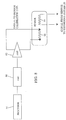
- FIG 8 shows the foregoing device where a digital-to-analog channel (DAC) 80 receives a command from the processor 48 based on various compensation algorithms such that it feeds a predefined analog signal into the compensation part of the data acquisition unit.
- the analog signal can be provided by a calibration winding or an additional winding both represented by 92 in FIG 8 .
- An external winding is also possible as long as the resulting noise on the sensor output is lower than without such winding.
- Other compensation techniques are possible as long as the cause aforementioned noise reduction takes place. Such compensation may reduce the noise and significantly improve signal-to-noise ration without any phase distortion in the signal fidelity.
- An additional benefit may be to reduce processing time required to reduce the signal to noise ratio or to reduce transmitter power requirements when the unit is used to record a controlled source signal similar to the type described by Strack, 1992. It may also be advantageous to couple the analogue feedback with digital feedback such as but not limited too where the remaining noise portion of a previous signal window is subtracted from its consecutive window such that the noise is reduced to almost zero.
- a data acquisition unit and a geophysical data acquisition system using such data acquisition units as described herein may have one or more of the following advantages.
- the signal acquisition unit may use any type of geophysical sensor coupled to any of the input channels, and the acquisition unit will automatically configure it so that amplification, filtering and digitization are optimized for the particular type of sensor coupled to such input channel. All the input channels may be identical, which enables use of the data acquisition unit for general-purpose applications.
- the input channels are variable, such as is common in magnetotelluric prospecting wherein electric and magnetic fields are acquired, or in cases where seismic and/or electromagnetic sensors are mixed, each sensor maybe codes as to the sensor type and/or category, or in case of digital sensors as uniquely identified sensors. This allows the appropriate calibration data to be either merged with acquired signal data. Time saving and data reductions results.
- a mesh network may be used for transmitting geophysical survey measurements from the data acquisition unit to the recording unit substantially in real-time for data quality analysis and checking.
- the acquisition unit may have an internal digital to analog converter to enable compensation for external voltage offsets.
- the data acquisition unit may have a digital sampling rate up to 100 kHz to cover high frequency signals e.g., up to 50 kHz.
- the example data acquisition unit may combine both low frequency and high frequency sampled input channels, providing minimized power consumption with respect to the required data quality for each sensor type. Identification of sensor and noise compensation feedback shown in FIG 8 further reduces power consumption and may provide a balanced system
- the data acquisition timing may be synchronized with a global positioning system signal absolute time reference; an absolute time signal can be sent from the recording unit to any data acquisition unit in the absence of a detectable time reference (e.g., GPS) signal.
- the acquisition timing may also be provided in such circumstances by a temperature stabilized clock oscillator crystal.
- the data acquisition unit may automatically re-synchronize to an absolute time reference when a time reference signal, e.g., GPS signal is once again detectable by the data acquisition unit.
- the already digitized data output therefrom may be sent to the recording system 20 as shown in FIG 9 .
- the digital sensors 100 can produce at least digital data which can then be transmitted to the recording system 20 either by wired or wireless connection 102 or stored on a memory device (not shown separately in FIG. 9 )
- the digital sensor 100 may already include all the functions of the recording system 20 including network adaption.
- this requires very careful shielding and grounding design as memory write action can be ready by magnetic sensors.
- Magnetic sensors include magnetic field and seismic sensors. Being able to realize this with such array architecture allows minimizing system noise and allows signal from noise splitting by allowing parallel signal amplification in a balanced mode with low power consumption. This allows significant cost and size reduction of highly specialize geophysical acquisition systems.
Landscapes
- Life Sciences & Earth Sciences (AREA)
- Physics & Mathematics (AREA)
- Engineering & Computer Science (AREA)
- Geophysics (AREA)
- General Life Sciences & Earth Sciences (AREA)
- General Physics & Mathematics (AREA)
- Remote Sensing (AREA)
- Acoustics & Sound (AREA)
- Environmental & Geological Engineering (AREA)
- Geology (AREA)
- Theoretical Computer Science (AREA)
- Geophysics And Detection Of Objects (AREA)
- Circuits Of Receivers In General (AREA)
Claims (14)
- Geophysikalisches Datenerfassungssystem, umfassend:mindestens einen geophysikalischen Sensor (12, 14, 16, 18), wobei dem mindestens einen geophysikalischen Sensor ein Signalgenerator zugeordnet ist, der dazu ausgelegt ist, ein Signal zu erzeugen, das einem Typ des mindestens einen geophysikalischen Sensors (12, 14, 16, 18) entspricht, undmindestens eine geophysikalische Signalerfassungseinheit (10) mit einer Vielzahl von Eingangskanälen und einem zentralen Prozessor (48), wobei der mindestens eine geophysikalische Sensor (12, 14, 16, 18) in Signalverbindung mit einem der Vielzahl von Eingangskanälen steht, wobei die Vielzahl von Eingangskanälen jeweils in Verbindung mit dem zentralen Prozessor (48) steht, wobei der zentrale Prozessor (48) dazu konfiguriert ist, den Typ des mit dem jeweiligen der Eingangskanäle gekoppelten Sensors anhand des an dem jeweiligen der Eingangskanäle empfangenen Signals abzufragen, wobei die mindestens eine Signalerfassungseinheit (10) Verstärkungs-, Filter- und Digitalisierungsschaltungen umfasst, die als Reaktion auf den durch das erfasste Signal identifizierten Sensortyp automatisch konfigurierbar sind,dadurch gekennzeichnet, dass es ferner einen Wellenformgenerator umfasst, der mit der mindestens einen geophysikalischen Signalerfassungseinheit (10) verbunden ist, wobei der Wellenformgenerator dazu konfiguriert ist, einen Strom mit einer ausgewählten Wellenform zu erzeugen, wobei der Wellenformgenerator in Signalverbindung mit mindestens einem der Eingangskanäle steht,wobei der Wellenformgenerator dazu konfiguriert ist, ausgewählte Arten von Rauschen in Signalen zu erfassen, die von dem mindestens einen geophysikalischen Sensor (12, 14, 16, 18) übermittelt werden, wobei der Wellenformgenerator dazu konfiguriert ist, eine Wellenform zu erzeugen, die einer Umkehrung der ausgewählten Art von Rauschen entspricht, und die Umkehrung an den Eingangskanal anzulegen, der dem mindestens einen geophysikalischen Sensor (12, 14, 16, 18) zugeordnet ist,wobei die ausgewählte Art von Rauschen eine Vorspannung umfasst, die an einem Sensor für ein elektrisches Feld anliegt, undwobei der Wellenformgenerator ferner dazu konfiguriert ist, dass er eine Gleichspannungs-Offsetspannung zu erzeugen, um die Vorspannung als Reaktion auf den durch das erfasste Signal identifizierten Sensortyp zu kompensieren.
- Geophysikalisches Datenerfassungssystem nach Anspruch 1, wobei der Signalgenerator einen kodierten Widerstand (R) oder einen Festwertspeicher (58) umfasst.
- Geophysikalisches Datenerfassungssystem nach Anspruch 1, wobei die Verstärkungsschaltung einen Verstärker mit programmierbarer Verstärkung (30) umfasst.
- Geophysikalisches Datenerfassungssystem nach Anspruch 1, wobei die Filterschaltung eine Vielzahl von analogen Tiefpassfiltern (32, 34, 36) umfasst, wobei eines der Vielzahl von Tiefpassfiltern auf der Grundlage des erfassten Signals wahlweise zwischen die Verstärkungsschaltung und die Digitalisierungsschaltung geschaltet werden kann.
- Geophysikalisches Datenerfassungssystem nach Anspruch 1, wobei die Filterschaltung ein digital gesteuertes Filter (33) umfasst, das zwischen die Verstärkungsschaltung und die Digitalisierungsschaltung geschaltet ist, wobei eine Grenzfrequenz des digital gesteuerten Filters auf der Grundlage des erfassten Signals ausgewählt wird.
- Geophysikalisches Datenerfassungssystem nach Anspruch 1, wobei die Digitalisierungsschaltung einen Analog-Digital-Wandler (38) mit wählbarer Abtastrate umfasst, wobei eine Abtastrate des Analog-Digital-Wandlers auf der Grundlage des erfassten Signals ausgewählt wird.
- Geophysikalisches Datenerfassungssystem nach Anspruch 1, wobei der mindestens eine geophysikalische Sensor mindestens einen von einem seismischen Sensor (12), einem Sensor für ein elektrisches Feld (18), einem Magnetfeldamplitudensensor (16) und einem Magnetometer (14) umfasst.
- Geophysikalisches Datenerfassungssystem nach Anspruch 1, ferner umfassend einen Empfänger für ein Absolutzeit-Referenzsignal, der mit der mindestens einen Signalerfassungseinheit (10) verbunden ist, wobei ein Absolutzeitsignal, das von dem Empfänger für das Absolutzeit-Referenzsignal erfasst wird, dazu verwendet wird, die Signalerfassung durch den mindestens einen geophysikalischen Sensor in Bezug auf die Absolutzeit zu synchronisieren.
- Geophysikalisches Datenerfassungssystem nach Anspruch 1, wobei die ausgewählte Art von Rauschen mindestens eines von 50-Hertz-Netzleitungsrauschen und 60-Hertz-Netzleitungsrauschen umfasst.
- Geophysikalisches Datenerfassungssystem nach Anspruch 1, wobei die mindestens eine geophysikalische Signalerfassungseinheit einen Funktransceiver (52) zum Übertragen digitalisierter Sensorsignale an ein Aufzeichnungssystem (20) umfasst, das an einem ausgewählten Ort getrennt von der mindestens einen geophysikalischen Signalerfassungseinheit angeordnet ist.
- Geophysikalisches Datenerfassungssystem nach Anspruch 10, ferner umfassend eine Vielzahl von geophysikalischen Signalerfassungseinheiten, die jeweils einen Funktransceiver (52) umfassen, wobei die Funktransceiver (52) einen Teil eines Maschennetzes zur Kommunikation von digitalisierten Datensignalen an das Aufzeichnungssystem (20) bilden.
- Geophysikalisches Datenerfassungssystem nach Anspruch 1, wobei der zentrale Prozessor (48) dazu konfiguriert ist, die Verstärkungs-, Filter- und Digitalisierungsschaltungen zu betreiben.
- Geophysikalisches Datenerfassungssystem nach Anspruch 12, wobei der zentrale Prozessor (48) ferner einen Eingang (56) aufweist, der an eine Datenspeichervorrichtung (57) anschließbar ist, wobei die Datenspeichervorrichtung (57) kodierte Befehle für einen vorbestimmten Betrieb der Verstärkungs-, Filter- und Digitalisierungsschaltungen aufweist, die jedem der mehreren Eingangskanäle zugeordnet sind.
- Geophysikalisches Datenerfassungssystem nach Anspruch 1, wobei eine Rückkopplungsschaltung der Erfassungseinheit zur Steuerung der Sensoren ein externes Kompensationssignal in den Sensoren erzeugt, das Rauschen simuliert, und das ferner eine Rückkopplung umfasst, die dazu konfiguriert ist, dass das Rauschen zu minimieren.
Applications Claiming Priority (2)
| Application Number | Priority Date | Filing Date | Title |
|---|---|---|---|
| US13/347,775 US9057801B2 (en) | 2012-01-11 | 2012-01-11 | Geophysical data acquisition system |
| PCT/US2012/069398 WO2013106158A2 (en) | 2012-01-11 | 2012-12-13 | Geophysical data acquisition system |
Publications (3)
| Publication Number | Publication Date |
|---|---|
| EP2803140A2 EP2803140A2 (de) | 2014-11-19 |
| EP2803140B1 true EP2803140B1 (de) | 2020-10-14 |
| EP2803140B8 EP2803140B8 (de) | 2020-12-09 |
Family
ID=47505339
Family Applications (1)
| Application Number | Title | Priority Date | Filing Date |
|---|---|---|---|
| EP12810492.4A Active EP2803140B8 (de) | 2012-01-11 | 2012-12-13 | Geophysikalisches datenerfassungssystem |
Country Status (5)
| Country | Link |
|---|---|
| US (1) | US9057801B2 (de) |
| EP (1) | EP2803140B8 (de) |
| CN (1) | CN104115405B (de) |
| CA (1) | CA2859176C (de) |
| WO (1) | WO2013106158A2 (de) |
Families Citing this family (10)
| Publication number | Priority date | Publication date | Assignee | Title |
|---|---|---|---|---|
| US10033473B1 (en) * | 2017-01-23 | 2018-07-24 | Keysight Technologies, Inc. | Systems and methods for performing multiple input, multiple output (MIMO) over-the-air testing |
| EA201991948A1 (ru) * | 2017-03-08 | 2020-03-06 | Инова Лтд. | Устройства сбора сейсмических данных и соответствующие способы |
| CN107170349A (zh) * | 2017-07-19 | 2017-09-15 | 东华理工大学 | 基于无线网络的勘探地球物理教学实验数据采集装置 |
| JP6869884B2 (ja) * | 2017-12-26 | 2021-05-12 | 株式会社日立製作所 | センサ端末およびセンサシステム |
| CN109100821A (zh) * | 2018-09-21 | 2018-12-28 | 安徽惠洲地质安全研究院股份有限公司 | 多勘探地球物理场信号智能采集装置及方法 |
| GB201915110D0 (en) * | 2019-10-18 | 2019-12-04 | Bp Exploration Operating Co Ltd | Seismic sensor gain |
| JP7466377B2 (ja) * | 2020-05-21 | 2024-04-12 | 東京エレクトロン株式会社 | 基板処理装置 |
| US12160212B2 (en) | 2021-01-21 | 2024-12-03 | Maxim Integrated Products, Inc. | Offset voltage compensation |
| US20240288598A1 (en) * | 2021-06-04 | 2024-08-29 | Stephen BUSUTTIL | A geophysical data acquisition device |
| CN119936967B (zh) * | 2023-11-03 | 2025-10-21 | 中国石油天然气集团有限公司 | 用于对可控震源振动器信号采集的姿态传感器电路 |
Citations (3)
| Publication number | Priority date | Publication date | Assignee | Title |
|---|---|---|---|---|
| US3704444A (en) * | 1970-06-01 | 1972-11-28 | Western Geophysical Co | Seismic data processing method and system |
| US5335186A (en) * | 1990-03-30 | 1994-08-02 | Texas Instruments Incorporated | Intelligent programmable sensing |
| WO1996001411A1 (en) * | 1994-07-01 | 1996-01-18 | Ada Technologies, Inc. | Portable data collection device |
Family Cites Families (18)
| Publication number | Priority date | Publication date | Assignee | Title |
|---|---|---|---|---|
| US4944036A (en) * | 1970-12-28 | 1990-07-24 | Hyatt Gilbert P | Signature filter system |
| US4039806A (en) * | 1975-10-01 | 1977-08-02 | Chevron Research Company | Synthesizer for testing elements of a geophysical data acquisition system |
| USRE31559E (en) * | 1976-06-28 | 1984-04-17 | Chevron Research Company | Combination flyer-jumper associated with a geophysical data acquisition system and method of manufacture |
| US4628493A (en) * | 1982-02-22 | 1986-12-09 | Hydroacoustics Inc. | Sensor system with time division multiplexing telemetry |
| US5918194A (en) | 1996-08-01 | 1999-06-29 | Keithley Instruments, Inc. | Integrated modular measurement system having configurable firmware architecture and modular mechanical parts |
| US5920828A (en) * | 1997-06-02 | 1999-07-06 | Baker Hughes Incorporated | Quality control seismic data processing system |
| US6236212B1 (en) * | 1998-06-22 | 2001-05-22 | The United States Of America As Represented By The Secretary Of The Interior | Induced polarization system using towed cable carrying transmitters and receivers for identifying minerals on the ocean floor |
| FR2787888B1 (fr) * | 1998-12-24 | 2001-03-23 | Sercel Rech Const Elect | Systeme perfectionne d'acquisition de donnees geophysiques |
| AUPS306802A0 (en) * | 2002-06-20 | 2002-07-11 | Wmc Resources Ltd | A data acquisition unit, system and method for geophysical data |
| US7219037B2 (en) * | 2002-10-24 | 2007-05-15 | Lecroy Corporation | High bandwidth oscilloscope |
| NO326506B1 (no) * | 2003-07-10 | 2008-12-15 | Norsk Hydro As | Et maringeofysisk innsamlingssystem med en kabel med seismiske kilder og mottakere og elektromagnteiske kilder og mottakere |
| US7088276B1 (en) * | 2004-02-13 | 2006-08-08 | Samplify Systems Llc | Enhanced data converters using compression and decompression |
| US7009533B1 (en) * | 2004-02-13 | 2006-03-07 | Samplify Systems Llc | Adaptive compression and decompression of bandlimited signals |
| US7773457B2 (en) | 2005-10-07 | 2010-08-10 | Wireless Seismic | Wireless exploration seismic system |
| US8026723B2 (en) | 2007-04-30 | 2011-09-27 | Kjt Enterprises, Inc. | Multi-component marine electromagnetic signal acquisition method |
| AU2008299384B2 (en) * | 2007-05-14 | 2013-07-11 | Ocean Floor Geophysics Inc. | Underwater electric field electromagnetic prospecting system |
| CN201680847U (zh) * | 2010-04-30 | 2010-12-22 | 浙江天煌科技实业有限公司 | 一种能识别传感器类型的测量接口装置 |
| CN102202093B (zh) * | 2011-05-12 | 2016-01-20 | 南京中兴新软件有限责任公司 | 一种实现传感器适配的方法和系统 |
-
2012
- 2012-01-11 US US13/347,775 patent/US9057801B2/en active Active
- 2012-12-13 CA CA2859176A patent/CA2859176C/en active Active
- 2012-12-13 WO PCT/US2012/069398 patent/WO2013106158A2/en not_active Ceased
- 2012-12-13 CN CN201280066824.8A patent/CN104115405B/zh not_active Expired - Fee Related
- 2012-12-13 EP EP12810492.4A patent/EP2803140B8/de active Active
Patent Citations (3)
| Publication number | Priority date | Publication date | Assignee | Title |
|---|---|---|---|---|
| US3704444A (en) * | 1970-06-01 | 1972-11-28 | Western Geophysical Co | Seismic data processing method and system |
| US5335186A (en) * | 1990-03-30 | 1994-08-02 | Texas Instruments Incorporated | Intelligent programmable sensing |
| WO1996001411A1 (en) * | 1994-07-01 | 1996-01-18 | Ada Technologies, Inc. | Portable data collection device |
Also Published As
| Publication number | Publication date |
|---|---|
| CA2859176A1 (en) | 2013-07-18 |
| CA2859176C (en) | 2016-10-04 |
| CN104115405B (zh) | 2017-11-14 |
| US9057801B2 (en) | 2015-06-16 |
| WO2013106158A2 (en) | 2013-07-18 |
| EP2803140B8 (de) | 2020-12-09 |
| WO2013106158A3 (en) | 2013-10-17 |
| CN104115405A (zh) | 2014-10-22 |
| US20130176821A1 (en) | 2013-07-11 |
| EP2803140A2 (de) | 2014-11-19 |
Similar Documents
| Publication | Publication Date | Title |
|---|---|---|
| EP2803140B1 (de) | Geophysikalisches datenerfassungssystem | |
| US8736264B2 (en) | NMR logging apparatus | |
| US9720129B2 (en) | Electronics for a thin bed array induction logging system | |
| AU2003240290B2 (en) | A data acquisition unit, system and method for geophysical data | |
| EP1470437B1 (de) | Akustisches vermessungswerkzeug mit programmierbaren quellensignalformen | |
| AU2004293750B2 (en) | Integrated sensor system for measuring electric and/or magnetic field vector components | |
| US20130300420A1 (en) | Acquisition System and Method for Towed Electromagnetic Sensor Cable and Source | |
| KR101660768B1 (ko) | 지진 가속도 센서의 상태 정보 제어 장치 및 방법 | |
| WO2020139813A1 (en) | Miniaturized nmr tool electronics | |
| EP2761319A1 (de) | Erkennung von kernquadrupolresonanz von kontinuierlichen rabi-übergängen | |
| KR20200060627A (ko) | 센서와 지진 기록계 일체형 지진 감지 장치 | |
| CN207598225U (zh) | 油基泥浆电成像测井仪频率自适应系统 | |
| US20260056343A1 (en) | Methods and systems for phase sensitive electromagnetic sensing via physically separated transmitter and receiver modules | |
| CN107956468B (zh) | 油基泥浆电成像测井仪频率自适应系统 | |
| Bahner et al. | Multichannel magnetic resonance sounding with wirelessly operated coils–A design study | |
| Bahner et al. | Multichannel magnetic resonance sounding with wirelessly operated coils: A study design |
Legal Events
| Date | Code | Title | Description |
|---|---|---|---|
| PUAI | Public reference made under article 153(3) epc to a published international application that has entered the european phase |
Free format text: ORIGINAL CODE: 0009012 |
|
| 17P | Request for examination filed |
Effective date: 20140811 |
|
| AK | Designated contracting states |
Kind code of ref document: A2 Designated state(s): AL AT BE BG CH CY CZ DE DK EE ES FI FR GB GR HR HU IE IS IT LI LT LU LV MC MK MT NL NO PL PT RO RS SE SI SK SM TR |
|
| DAX | Request for extension of the european patent (deleted) | ||
| STAA | Information on the status of an ep patent application or granted ep patent |
Free format text: STATUS: EXAMINATION IS IN PROGRESS |
|
| 17Q | First examination report despatched |
Effective date: 20190418 |
|
| REG | Reference to a national code |
Ref country code: DE Ref legal event code: R079 Ref document number: 602012072812 Country of ref document: DE Free format text: PREVIOUS MAIN CLASS: H03M0001120000 Ipc: G01V0001160000 |
|
| GRAP | Despatch of communication of intention to grant a patent |
Free format text: ORIGINAL CODE: EPIDOSNIGR1 |
|
| STAA | Information on the status of an ep patent application or granted ep patent |
Free format text: STATUS: GRANT OF PATENT IS INTENDED |
|
| RIC1 | Information provided on ipc code assigned before grant |
Ipc: G01V 1/16 20060101AFI20200414BHEP Ipc: G01V 1/22 20060101ALI20200414BHEP Ipc: H03M 1/12 20060101ALI20200414BHEP Ipc: G01V 11/00 20060101ALI20200414BHEP Ipc: G01D 3/02 20060101ALI20200414BHEP |
|
| INTG | Intention to grant announced |
Effective date: 20200429 |
|
| GRAS | Grant fee paid |
Free format text: ORIGINAL CODE: EPIDOSNIGR3 |
|
| GRAA | (expected) grant |
Free format text: ORIGINAL CODE: 0009210 |
|
| STAA | Information on the status of an ep patent application or granted ep patent |
Free format text: STATUS: THE PATENT HAS BEEN GRANTED |
|
| AK | Designated contracting states |
Kind code of ref document: B1 Designated state(s): AL AT BE BG CH CY CZ DE DK EE ES FI FR GB GR HR HU IE IS IT LI LT LU LV MC MK MT NL NO PL PT RO RS SE SI SK SM TR |
|
| REG | Reference to a national code |
Ref country code: GB Ref legal event code: FG4D |
|
| REG | Reference to a national code |
Ref country code: AT Ref legal event code: REF Ref document number: 1324129 Country of ref document: AT Kind code of ref document: T Effective date: 20201015 Ref country code: CH Ref legal event code: EP |
|
| REG | Reference to a national code |
Ref country code: DE Ref legal event code: R096 Ref document number: 602012072812 Country of ref document: DE |
|
| RAP2 | Party data changed (patent owner data changed or rights of a patent transferred) |
Owner name: KJT ENTERPRISES, INC. |
|
| REG | Reference to a national code |
Ref country code: IE Ref legal event code: FG4D |
|
| REG | Reference to a national code |
Ref country code: CH Ref legal event code: PK Free format text: BERICHTIGUNG B8 |
|
| REG | Reference to a national code |
Ref country code: NO Ref legal event code: T2 Effective date: 20201014 |
|
| PGFP | Annual fee paid to national office [announced via postgrant information from national office to epo] |
Ref country code: NO Payment date: 20201228 Year of fee payment: 9 |
|
| REG | Reference to a national code |
Ref country code: AT Ref legal event code: MK05 Ref document number: 1324129 Country of ref document: AT Kind code of ref document: T Effective date: 20201014 |
|
| REG | Reference to a national code |
Ref country code: NL Ref legal event code: MP Effective date: 20201014 |
|
| PG25 | Lapsed in a contracting state [announced via postgrant information from national office to epo] |
Ref country code: PT Free format text: LAPSE BECAUSE OF FAILURE TO SUBMIT A TRANSLATION OF THE DESCRIPTION OR TO PAY THE FEE WITHIN THE PRESCRIBED TIME-LIMIT Effective date: 20210215 Ref country code: NL Free format text: LAPSE BECAUSE OF FAILURE TO SUBMIT A TRANSLATION OF THE DESCRIPTION OR TO PAY THE FEE WITHIN THE PRESCRIBED TIME-LIMIT Effective date: 20201014 Ref country code: FI Free format text: LAPSE BECAUSE OF FAILURE TO SUBMIT A TRANSLATION OF THE DESCRIPTION OR TO PAY THE FEE WITHIN THE PRESCRIBED TIME-LIMIT Effective date: 20201014 Ref country code: RS Free format text: LAPSE BECAUSE OF FAILURE TO SUBMIT A TRANSLATION OF THE DESCRIPTION OR TO PAY THE FEE WITHIN THE PRESCRIBED TIME-LIMIT Effective date: 20201014 Ref country code: GR Free format text: LAPSE BECAUSE OF FAILURE TO SUBMIT A TRANSLATION OF THE DESCRIPTION OR TO PAY THE FEE WITHIN THE PRESCRIBED TIME-LIMIT Effective date: 20210115 |
|
| REG | Reference to a national code |
Ref country code: LT Ref legal event code: MG4D |
|
| PG25 | Lapsed in a contracting state [announced via postgrant information from national office to epo] |
Ref country code: IS Free format text: LAPSE BECAUSE OF FAILURE TO SUBMIT A TRANSLATION OF THE DESCRIPTION OR TO PAY THE FEE WITHIN THE PRESCRIBED TIME-LIMIT Effective date: 20210214 Ref country code: LV Free format text: LAPSE BECAUSE OF FAILURE TO SUBMIT A TRANSLATION OF THE DESCRIPTION OR TO PAY THE FEE WITHIN THE PRESCRIBED TIME-LIMIT Effective date: 20201014 Ref country code: SE Free format text: LAPSE BECAUSE OF FAILURE TO SUBMIT A TRANSLATION OF THE DESCRIPTION OR TO PAY THE FEE WITHIN THE PRESCRIBED TIME-LIMIT Effective date: 20201014 Ref country code: PL Free format text: LAPSE BECAUSE OF FAILURE TO SUBMIT A TRANSLATION OF THE DESCRIPTION OR TO PAY THE FEE WITHIN THE PRESCRIBED TIME-LIMIT Effective date: 20201014 Ref country code: AT Free format text: LAPSE BECAUSE OF FAILURE TO SUBMIT A TRANSLATION OF THE DESCRIPTION OR TO PAY THE FEE WITHIN THE PRESCRIBED TIME-LIMIT Effective date: 20201014 Ref country code: BG Free format text: LAPSE BECAUSE OF FAILURE TO SUBMIT A TRANSLATION OF THE DESCRIPTION OR TO PAY THE FEE WITHIN THE PRESCRIBED TIME-LIMIT Effective date: 20210114 Ref country code: ES Free format text: LAPSE BECAUSE OF FAILURE TO SUBMIT A TRANSLATION OF THE DESCRIPTION OR TO PAY THE FEE WITHIN THE PRESCRIBED TIME-LIMIT Effective date: 20201014 |
|
| PG25 | Lapsed in a contracting state [announced via postgrant information from national office to epo] |
Ref country code: HR Free format text: LAPSE BECAUSE OF FAILURE TO SUBMIT A TRANSLATION OF THE DESCRIPTION OR TO PAY THE FEE WITHIN THE PRESCRIBED TIME-LIMIT Effective date: 20201014 |
|
| REG | Reference to a national code |
Ref country code: DE Ref legal event code: R097 Ref document number: 602012072812 Country of ref document: DE |
|
| PG25 | Lapsed in a contracting state [announced via postgrant information from national office to epo] |
Ref country code: LT Free format text: LAPSE BECAUSE OF FAILURE TO SUBMIT A TRANSLATION OF THE DESCRIPTION OR TO PAY THE FEE WITHIN THE PRESCRIBED TIME-LIMIT Effective date: 20201014 Ref country code: SK Free format text: LAPSE BECAUSE OF FAILURE TO SUBMIT A TRANSLATION OF THE DESCRIPTION OR TO PAY THE FEE WITHIN THE PRESCRIBED TIME-LIMIT Effective date: 20201014 Ref country code: RO Free format text: LAPSE BECAUSE OF FAILURE TO SUBMIT A TRANSLATION OF THE DESCRIPTION OR TO PAY THE FEE WITHIN THE PRESCRIBED TIME-LIMIT Effective date: 20201014 Ref country code: SM Free format text: LAPSE BECAUSE OF FAILURE TO SUBMIT A TRANSLATION OF THE DESCRIPTION OR TO PAY THE FEE WITHIN THE PRESCRIBED TIME-LIMIT Effective date: 20201014 Ref country code: CZ Free format text: LAPSE BECAUSE OF FAILURE TO SUBMIT A TRANSLATION OF THE DESCRIPTION OR TO PAY THE FEE WITHIN THE PRESCRIBED TIME-LIMIT Effective date: 20201014 Ref country code: EE Free format text: LAPSE BECAUSE OF FAILURE TO SUBMIT A TRANSLATION OF THE DESCRIPTION OR TO PAY THE FEE WITHIN THE PRESCRIBED TIME-LIMIT Effective date: 20201014 |
|
| REG | Reference to a national code |
Ref country code: CH Ref legal event code: PL |
|
| PLBE | No opposition filed within time limit |
Free format text: ORIGINAL CODE: 0009261 |
|
| STAA | Information on the status of an ep patent application or granted ep patent |
Free format text: STATUS: NO OPPOSITION FILED WITHIN TIME LIMIT |
|
| PG25 | Lapsed in a contracting state [announced via postgrant information from national office to epo] |
Ref country code: DK Free format text: LAPSE BECAUSE OF FAILURE TO SUBMIT A TRANSLATION OF THE DESCRIPTION OR TO PAY THE FEE WITHIN THE PRESCRIBED TIME-LIMIT Effective date: 20201014 Ref country code: MC Free format text: LAPSE BECAUSE OF FAILURE TO SUBMIT A TRANSLATION OF THE DESCRIPTION OR TO PAY THE FEE WITHIN THE PRESCRIBED TIME-LIMIT Effective date: 20201014 |
|
| REG | Reference to a national code |
Ref country code: BE Ref legal event code: MM Effective date: 20201231 |
|
| 26N | No opposition filed |
Effective date: 20210715 |
|
| PG25 | Lapsed in a contracting state [announced via postgrant information from national office to epo] |
Ref country code: LU Free format text: LAPSE BECAUSE OF NON-PAYMENT OF DUE FEES Effective date: 20201213 Ref country code: AL Free format text: LAPSE BECAUSE OF FAILURE TO SUBMIT A TRANSLATION OF THE DESCRIPTION OR TO PAY THE FEE WITHIN THE PRESCRIBED TIME-LIMIT Effective date: 20201014 Ref country code: IT Free format text: LAPSE BECAUSE OF FAILURE TO SUBMIT A TRANSLATION OF THE DESCRIPTION OR TO PAY THE FEE WITHIN THE PRESCRIBED TIME-LIMIT Effective date: 20201014 Ref country code: IE Free format text: LAPSE BECAUSE OF NON-PAYMENT OF DUE FEES Effective date: 20201213 |
|
| PG25 | Lapsed in a contracting state [announced via postgrant information from national office to epo] |
Ref country code: CH Free format text: LAPSE BECAUSE OF NON-PAYMENT OF DUE FEES Effective date: 20201231 Ref country code: SI Free format text: LAPSE BECAUSE OF FAILURE TO SUBMIT A TRANSLATION OF THE DESCRIPTION OR TO PAY THE FEE WITHIN THE PRESCRIBED TIME-LIMIT Effective date: 20201014 Ref country code: LI Free format text: LAPSE BECAUSE OF NON-PAYMENT OF DUE FEES Effective date: 20201231 |
|
| PG25 | Lapsed in a contracting state [announced via postgrant information from national office to epo] |
Ref country code: IS Free format text: LAPSE BECAUSE OF FAILURE TO SUBMIT A TRANSLATION OF THE DESCRIPTION OR TO PAY THE FEE WITHIN THE PRESCRIBED TIME-LIMIT Effective date: 20210214 Ref country code: TR Free format text: LAPSE BECAUSE OF FAILURE TO SUBMIT A TRANSLATION OF THE DESCRIPTION OR TO PAY THE FEE WITHIN THE PRESCRIBED TIME-LIMIT Effective date: 20201014 Ref country code: MT Free format text: LAPSE BECAUSE OF FAILURE TO SUBMIT A TRANSLATION OF THE DESCRIPTION OR TO PAY THE FEE WITHIN THE PRESCRIBED TIME-LIMIT Effective date: 20201014 Ref country code: CY Free format text: LAPSE BECAUSE OF FAILURE TO SUBMIT A TRANSLATION OF THE DESCRIPTION OR TO PAY THE FEE WITHIN THE PRESCRIBED TIME-LIMIT Effective date: 20201014 |
|
| PG25 | Lapsed in a contracting state [announced via postgrant information from national office to epo] |
Ref country code: MK Free format text: LAPSE BECAUSE OF FAILURE TO SUBMIT A TRANSLATION OF THE DESCRIPTION OR TO PAY THE FEE WITHIN THE PRESCRIBED TIME-LIMIT Effective date: 20201014 |
|
| REG | Reference to a national code |
Ref country code: NO Ref legal event code: MMEP |
|
| PG25 | Lapsed in a contracting state [announced via postgrant information from national office to epo] |
Ref country code: BE Free format text: LAPSE BECAUSE OF NON-PAYMENT OF DUE FEES Effective date: 20201231 |
|
| PG25 | Lapsed in a contracting state [announced via postgrant information from national office to epo] |
Ref country code: NO Free format text: LAPSE BECAUSE OF NON-PAYMENT OF DUE FEES Effective date: 20211231 |
|
| PGFP | Annual fee paid to national office [announced via postgrant information from national office to epo] |
Ref country code: FR Payment date: 20221206 Year of fee payment: 11 |
|
| REG | Reference to a national code |
Ref country code: DE Ref legal event code: R082 Ref document number: 602012072812 Country of ref document: DE Representative=s name: CBDL PATENTANWAELTE GBR, DE Ref country code: DE Ref legal event code: R082 Ref document number: 602012072812 Country of ref document: DE Representative=s name: CBDL PATENTANWAELTE EGBR, DE |
|
| PGFP | Annual fee paid to national office [announced via postgrant information from national office to epo] |
Ref country code: GB Payment date: 20230123 Year of fee payment: 11 |
|
| GBPC | Gb: european patent ceased through non-payment of renewal fee |
Effective date: 20231213 |
|
| PG25 | Lapsed in a contracting state [announced via postgrant information from national office to epo] |
Ref country code: GB Free format text: LAPSE BECAUSE OF NON-PAYMENT OF DUE FEES Effective date: 20231213 |
|
| PG25 | Lapsed in a contracting state [announced via postgrant information from national office to epo] |
Ref country code: FR Free format text: LAPSE BECAUSE OF NON-PAYMENT OF DUE FEES Effective date: 20231231 |
|
| PG25 | Lapsed in a contracting state [announced via postgrant information from national office to epo] |
Ref country code: GB Free format text: LAPSE BECAUSE OF NON-PAYMENT OF DUE FEES Effective date: 20231213 Ref country code: FR Free format text: LAPSE BECAUSE OF NON-PAYMENT OF DUE FEES Effective date: 20231231 |
|
| PGFP | Annual fee paid to national office [announced via postgrant information from national office to epo] |
Ref country code: DE Payment date: 20260114 Year of fee payment: 14 |