EP2803318A1 - Steuerung von SAR-Werten in der Magnetresonanzbildgebung - Google Patents
Steuerung von SAR-Werten in der Magnetresonanzbildgebung Download PDFInfo
- Publication number
- EP2803318A1 EP2803318A1 EP20140168438 EP14168438A EP2803318A1 EP 2803318 A1 EP2803318 A1 EP 2803318A1 EP 20140168438 EP20140168438 EP 20140168438 EP 14168438 A EP14168438 A EP 14168438A EP 2803318 A1 EP2803318 A1 EP 2803318A1
- Authority
- EP
- European Patent Office
- Prior art keywords
- patient
- power
- coil
- transmit coil
- pulses
- Prior art date
- Legal status (The legal status is an assumption and is not a legal conclusion. Google has not performed a legal analysis and makes no representation as to the accuracy of the status listed.)
- Withdrawn
Links
Images


Classifications
-
- G—PHYSICS
- G01—MEASURING; TESTING
- G01R—MEASURING ELECTRIC VARIABLES; MEASURING MAGNETIC VARIABLES
- G01R33/00—Arrangements or instruments for measuring magnetic variables
- G01R33/20—Arrangements or instruments for measuring magnetic variables involving magnetic resonance
- G01R33/44—Arrangements or instruments for measuring magnetic variables involving magnetic resonance using nuclear magnetic resonance [NMR]
- G01R33/48—NMR imaging systems
- G01R33/54—Signal processing systems, e.g. using pulse sequences ; Generation or control of pulse sequences; Operator console
- G01R33/543—Control of the operation of the MR system, e.g. setting of acquisition parameters prior to or during MR data acquisition, dynamic shimming, use of one or more scout images for scan plane prescription
-
- A—HUMAN NECESSITIES
- A61—MEDICAL OR VETERINARY SCIENCE; HYGIENE
- A61B—DIAGNOSIS; SURGERY; IDENTIFICATION
- A61B5/00—Measuring for diagnostic purposes; Identification of persons
- A61B5/05—Detecting, measuring or recording for diagnosis by means of electric currents or magnetic fields; Measuring using microwaves or radio waves
- A61B5/055—Detecting, measuring or recording for diagnosis by means of electric currents or magnetic fields; Measuring using microwaves or radio waves involving electronic [EMR] or nuclear [NMR] magnetic resonance, e.g. magnetic resonance imaging
-
- G—PHYSICS
- G01—MEASURING; TESTING
- G01R—MEASURING ELECTRIC VARIABLES; MEASURING MAGNETIC VARIABLES
- G01R33/00—Arrangements or instruments for measuring magnetic variables
- G01R33/20—Arrangements or instruments for measuring magnetic variables involving magnetic resonance
- G01R33/28—Details of apparatus provided for in groups G01R33/44 - G01R33/64
- G01R33/288—Provisions within MR facilities for enhancing safety during MR, e.g. reduction of the specific absorption rate [SAR], detection of ferromagnetic objects in the scanner room
-
- G—PHYSICS
- G01—MEASURING; TESTING
- G01R—MEASURING ELECTRIC VARIABLES; MEASURING MAGNETIC VARIABLES
- G01R33/00—Arrangements or instruments for measuring magnetic variables
- G01R33/20—Arrangements or instruments for measuring magnetic variables involving magnetic resonance
- G01R33/28—Details of apparatus provided for in groups G01R33/44 - G01R33/64
- G01R33/32—Excitation or detection systems, e.g. using radio frequency signals
- G01R33/36—Electrical details, e.g. matching or coupling of the coil to the receiver
-
- G—PHYSICS
- G01—MEASURING; TESTING
- G01R—MEASURING ELECTRIC VARIABLES; MEASURING MAGNETIC VARIABLES
- G01R33/00—Arrangements or instruments for measuring magnetic variables
- G01R33/20—Arrangements or instruments for measuring magnetic variables involving magnetic resonance
- G01R33/44—Arrangements or instruments for measuring magnetic variables involving magnetic resonance using nuclear magnetic resonance [NMR]
- G01R33/48—NMR imaging systems
- G01R33/4806—Functional imaging of brain activation
Definitions
- This invention relates to a method of imaging while controlling maximum SAR values to avoid damage to the patient by application of excess RF power.
- the scanner control system ensures safety of the patient with respect to RF energy absorbed by the patient by calculating and controlling a specific-absorption rate (SAR) setting.
- SAR specific-absorption rate
- the SAR setting is based on many parameters including the patient height, weight, the anatomy to be imaged and the position of the patient table in the bore.
- DBS Deep Brain Stimulation
- generating imaging sequences based on SAR is problematic as the SAR is a calculated estimate, not a measured value.
- the protocols are normally adjusted to achieve optimum images, however due to patient loading, the optimum adjustment may exceed the safe delivered SAR limit. In order to ensure safe limits, the operator must de-rate the parameters to ensure safe operation based on the worst case load.
- US Patent 5,730,134 (Dumoulin) issued March 24 1998 to General Electric discloses the use of a system in which automatically an MRI scan is terminated or reduced in power in response to detection of a raised temperature within the body of the patient caused by RF heating of an electrode within the patient.
- the electrode is located within an invasive device inserted into the body and the temperature sensor is an optical thermocouple mounted also within the invasive device.
- US Patent 6,185,443 (Crowley) issued February 6 2001 to Boston Scientific discloses an interventional device for minimally invasive diagnostic and therapeutic procedures where the device or probe carries sensors with a display on a distal end of the device to display to the user the sensed data including temperature.
- a method for imaging a body part of a patient comprising:
- the measuring step is arranged using parameters related to the patient weight etc to measure SAR (Watts/kg) being delivered to the patient in real time.
- the stopping of the RF pulses acts to ensure the safety of a transmit coil which is independent of patient loading and use.
- the RF pulses are stopped by supplying a signal directly to an MR imaging system controlling the RF transmit coil arrangement to stop the imaging sequence.
- the RF pulses are also stopped by disconnecting RF coil.
- the RF pulses are stopped simply by disconnecting the RF transmit coil.
- the safe limit is the SAR value which is determined including parameters of the patient since SAR values are well known and previously calculated. However it is the power value which is actually determinative of the potential damage to the patient.
- the power is measured at a measurement unit associated with the RF transmit coil and separate from the MR imaging system.
- the imaging system may include a measuring system which measures the actual power being supplied as opposed to the conventional technique which calculates the pulse sequence using predetermined parameters in order to provide a sequence which is predicted or calculated to generate a required SAR value.
- the parameters of the patient are input manually into the measurement unit so that the unit has an interface for a manual input by the operator.
- the parameters can be obtained from the MR imaging system where of course the parameters concerned must be input before the imaging sequence is calculated.
- the power is measured by continually measuring instantaneous transmitted power which is integrated to calculate the average power delivered to the patient.
- the system shuts down the supply of the pulses to the RF transmit coil to ensure no damage can occur.
- the power is measured at a controller which contains a microprocessor and driver circuitry to turn off an RF Switch to the RF transmit coil.
- the power can be measured by detecting transmitted power through a directional coupler in a lead to the RF transmit coil.
- a sampling coil can be located at the RF transmit coil and is used as an alternative to or in addition to the directional coupler to detect the actual RF power applied.
- a bi-directional coupler can be used where the power is measured also by detecting reflected power signal from the bi-directional coupler in a lead to the RF transmit coil. In this way the power can be measured using one, two or all of the three separate techniques. This can ensure that errors or failures in any one of the systems can be found as a duplicative system to provide a fail-safe action.
- the operator is therefore not restricted and can obtain better images if the SAR being delivered is measured using the RF transmit coil itself. In this manner, the operator can achieve maximum quality without exceeding safe limits.
- the operator therefore is not restricted to predetermined maximum calculated values and can err on the side of obtaining the best images by increasing the power supplied, safe in the knowledge that the actual power supplied cannot exceed the maximum value.
- This invention measures the SAR (Watts / kg) being delivered to the patient in real time, and will stop the scan if the safe limit is exceeded. It does this by measuring the actual power delivered to the patient using directional couplers in the RF transmit coil. When the safe power level is exceeded a RF switch opens up to prevent any more RF from reaching the patient, and a logic signal can be sent to stop the scan.
- SAR Satts / kg
- the opening of the RF switch causes high reflected power that will force the scanner to terminate the sequence.
- the system requires parameters including the patient weight and age.
- the size or height of the patient is not a large contributor to the head size, which is necessary for calculating the SAR relative to the specific body part to be imaged. This can be manually entered into the controller before scanning starts, or can be automatically extracted from the scanner console before scanning commences.
- the patient weight is scaled according to the body part being exposed to the RF field, using the coil size and human body model.
- the invention has been described in the context of DBS lead implantation but it is also relevant to and can be used with the introduction of any invasive conducting structure inserted within the body during MR imaging and is not limited to imaging of the head. This could also be for interventional applications where catheters are placed in blood vessels.
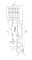
- the apparatus of the present invention is mainly shown only schematically as many of the components are well known to persons skilled in this art.
- a part of the patient shown at 10 which is located during at least a part of the procedure in an MR imaging system 11 including a magnet 12, RF coils 13 and a control and display system 14 for use in an invasive procedure for insertion of a conductive device into a patient while the insertion is guided using Magnetic Resonance Imaging.
- the conventional components further include a stereotactic positioner 15 and a cannula 16 located by the positioner 15 so as to define a path for insertion of a conductive device to a target location.
- the RF pulses generated at the MR system 14 are transmitted to the RF coil 13 along a conductor 20 which supplies those signals to a sensing unit 21 forming part of the coils 13 or associated with the coils 13.
- the sensing unit 21 includes an RF switch 24.
- the unit 21 can communicate to and from the control unit 14 along a communication path 22.
- the conventional components further include a conductive electrode 17 which in regard to DBS can be either a micro-recording electrode that is temporarily positioned at the target or a stimulation electrode intended to be located at and remain in position at a target location in the brain of the patient.
- a conductive electrode 17 which in regard to DBS can be either a micro-recording electrode that is temporarily positioned at the target or a stimulation electrode intended to be located at and remain in position at a target location in the brain of the patient.
- the imaging setup sequence is as follows:
- the coil 13 is plugged into the scanner control 14 and the patient weight is entered into the unit 21 by a manual interface 23 or read from the scanner console 14.
- the switch 24 is set to allow the transmitted RF to reach the coil 13.
- a directional coupler 3 samples the transmitted power and through detector 5, passes it on to an integrator/controller 6.
- the function of the integrator/controller is to sum the applied power to calculate the average SAR delivered to the patient.
- the controller 6 contains a microprocessor and driver circuitry to turn off the RF Switch 24 when the calculated SAR exceeds the safe limit that is programmed into the unit (for example, 0.1 W/kg for DBS leads).
- a sampling coil 7 located at the RF transmit coil 13 can be used in place of, or along with the coupled supply signal to detect the actual RF power applied and to stop the scanner.
- FIG. 3 Another method shown in Figure 3 of detecting the amount of SAR or power being delivered is to utilize the reflected power signal from a bi-directional coupler 3.
- the ports are labelled 'reflected power' and 'forward power'.
- the use of both detected values of the forward power and the reflected power has the advantage of providing an indication of the current loading and efficiency of the transmit coil, which is highly dependent on the patient loading and coil match.
- This arrangement has the benefit of forcing the scan to be stopped if the operator attempts to exceed safe limits for imaging when a patient with implants is being imaged.
- the SAR Calculation is typically based on a human cylinder model including the head, torso and two leg cylinders. This cylinder model is calculated for each patient depending on registration data (age, size, weight). According to the coil length it is assumed that the corresponding cylinder part (length and mass) is exposed to the B1-field. With these data, a calculation is made to set the B1 power limit that delivers the maximum SAR value of 0.1W/kg. This is compared with the measured value and if the measured value is higher, the scanning is stopped using the methods described earlier.
Landscapes
- Physics & Mathematics (AREA)
- Health & Medical Sciences (AREA)
- General Physics & Mathematics (AREA)
- Condensed Matter Physics & Semiconductors (AREA)
- Life Sciences & Earth Sciences (AREA)
- Nuclear Medicine, Radiotherapy & Molecular Imaging (AREA)
- High Energy & Nuclear Physics (AREA)
- General Health & Medical Sciences (AREA)
- Engineering & Computer Science (AREA)
- Radiology & Medical Imaging (AREA)
- Animal Behavior & Ethology (AREA)
- Medical Informatics (AREA)
- Molecular Biology (AREA)
- Surgery (AREA)
- Heart & Thoracic Surgery (AREA)
- Pathology (AREA)
- Public Health (AREA)
- Veterinary Medicine (AREA)
- Biophysics (AREA)
- Biomedical Technology (AREA)
- Signal Processing (AREA)
- Neurosurgery (AREA)
- Magnetic Resonance Imaging Apparatus (AREA)
Applications Claiming Priority (1)
| Application Number | Priority Date | Filing Date | Title |
|---|---|---|---|
| US201361824454P | 2013-05-17 | 2013-05-17 |
Publications (1)
| Publication Number | Publication Date |
|---|---|
| EP2803318A1 true EP2803318A1 (de) | 2014-11-19 |
Family
ID=50721648
Family Applications (1)
| Application Number | Title | Priority Date | Filing Date |
|---|---|---|---|
| EP20140168438 Withdrawn EP2803318A1 (de) | 2013-05-17 | 2014-05-15 | Steuerung von SAR-Werten in der Magnetresonanzbildgebung |
Country Status (2)
| Country | Link |
|---|---|
| US (1) | US20150015254A1 (de) |
| EP (1) | EP2803318A1 (de) |
Cited By (1)
| Publication number | Priority date | Publication date | Assignee | Title |
|---|---|---|---|---|
| CN109965878A (zh) * | 2017-12-28 | 2019-07-05 | 通用电气公司 | Mr成像系统中针对植入装置的安全提示系统及方法 |
Families Citing this family (7)
| Publication number | Priority date | Publication date | Assignee | Title |
|---|---|---|---|---|
| DE102013205651B4 (de) * | 2013-03-28 | 2024-09-12 | Siemens Healthineers Ag | Vorrichtung, Verfahren, System und Computerprogrammprodukt zur Steuerung von bildgebenden Verfahren und Systemen |
| KR101755600B1 (ko) * | 2016-01-08 | 2017-07-07 | 삼성전자주식회사 | 자기공명 영상장치에 사용되는 rf 수신 코일 유닛 |
| US10672520B1 (en) * | 2016-03-02 | 2020-06-02 | AltaSim Technologies, LLC | Precision medicine approach to improving patient safety and access to MRI |
| JP6147450B1 (ja) * | 2017-01-04 | 2017-06-14 | 株式会社日立製作所 | 磁気共鳴イメージング装置、および、その作動方法 |
| JP6965016B2 (ja) * | 2017-04-27 | 2021-11-10 | キヤノンメディカルシステムズ株式会社 | 磁気共鳴イメージング装置及びその調整方法 |
| CN113303781B (zh) * | 2021-04-30 | 2022-05-13 | 鑫高益医疗设备股份有限公司 | 门控同步的磁共振sar值监控方法、装置、存储介质及系统 |
| CN115685030A (zh) * | 2021-07-30 | 2023-02-03 | 上海联影医疗科技股份有限公司 | 磁共振射频发射系统及磁共振系统射频安全监控方法 |
Citations (10)
| Publication number | Priority date | Publication date | Assignee | Title |
|---|---|---|---|---|
| US5209233A (en) | 1985-08-09 | 1993-05-11 | Picker International, Inc. | Temperature sensing and control system for cardiac monitoring electrodes |
| JPH05317287A (ja) * | 1992-05-14 | 1993-12-03 | Toshiba Corp | 磁気共鳴イメージング装置 |
| US5730134A (en) | 1996-09-09 | 1998-03-24 | General Electric Company | System to monitor temperature near an invasive device during magnetic resonance procedures |
| US5916161A (en) * | 1995-09-13 | 1999-06-29 | Kabushiki Kaisha Toshiba | Magnetic resonance imaging apparatus with temperature measurement function |
| US6185443B1 (en) | 1997-09-29 | 2001-02-06 | Boston Scientific Corporation | Visible display for an interventional device |
| US20020093336A1 (en) * | 2000-09-27 | 2002-07-18 | Bernstein Matthew A. | Mri rf power monitor |
| EP1629773A1 (de) * | 2004-08-30 | 2006-03-01 | Kabushiki Kaisha Toshiba | Diagnosegerät für magnetische Resonanzuntersuchungen |
| US20070024283A1 (en) * | 2004-08-04 | 2007-02-01 | Wolfgang Bielmeier | Method, device and magnetic resonance tomography system for monitoring emitted RF energy |
| US20080157765A1 (en) * | 2006-12-28 | 2008-07-03 | Joerg Ulrich Fontius | Method and device for monitoring radio-frequency exposure in a magnetic resonance measurement |
| US20110109312A1 (en) * | 2009-11-12 | 2011-05-12 | Masaaki Yamanaka | Magnetic resonance imaging apparatus and magnetic resonance imaging method |
-
2014
- 2014-05-14 US US14/277,252 patent/US20150015254A1/en not_active Abandoned
- 2014-05-15 EP EP20140168438 patent/EP2803318A1/de not_active Withdrawn
Patent Citations (10)
| Publication number | Priority date | Publication date | Assignee | Title |
|---|---|---|---|---|
| US5209233A (en) | 1985-08-09 | 1993-05-11 | Picker International, Inc. | Temperature sensing and control system for cardiac monitoring electrodes |
| JPH05317287A (ja) * | 1992-05-14 | 1993-12-03 | Toshiba Corp | 磁気共鳴イメージング装置 |
| US5916161A (en) * | 1995-09-13 | 1999-06-29 | Kabushiki Kaisha Toshiba | Magnetic resonance imaging apparatus with temperature measurement function |
| US5730134A (en) | 1996-09-09 | 1998-03-24 | General Electric Company | System to monitor temperature near an invasive device during magnetic resonance procedures |
| US6185443B1 (en) | 1997-09-29 | 2001-02-06 | Boston Scientific Corporation | Visible display for an interventional device |
| US20020093336A1 (en) * | 2000-09-27 | 2002-07-18 | Bernstein Matthew A. | Mri rf power monitor |
| US20070024283A1 (en) * | 2004-08-04 | 2007-02-01 | Wolfgang Bielmeier | Method, device and magnetic resonance tomography system for monitoring emitted RF energy |
| EP1629773A1 (de) * | 2004-08-30 | 2006-03-01 | Kabushiki Kaisha Toshiba | Diagnosegerät für magnetische Resonanzuntersuchungen |
| US20080157765A1 (en) * | 2006-12-28 | 2008-07-03 | Joerg Ulrich Fontius | Method and device for monitoring radio-frequency exposure in a magnetic resonance measurement |
| US20110109312A1 (en) * | 2009-11-12 | 2011-05-12 | Masaaki Yamanaka | Magnetic resonance imaging apparatus and magnetic resonance imaging method |
Cited By (1)
| Publication number | Priority date | Publication date | Assignee | Title |
|---|---|---|---|---|
| CN109965878A (zh) * | 2017-12-28 | 2019-07-05 | 通用电气公司 | Mr成像系统中针对植入装置的安全提示系统及方法 |
Also Published As
| Publication number | Publication date |
|---|---|
| US20150015254A1 (en) | 2015-01-15 |
Similar Documents
| Publication | Publication Date | Title |
|---|---|---|
| EP2803318A1 (de) | Steuerung von SAR-Werten in der Magnetresonanzbildgebung | |
| JP5455926B2 (ja) | 磁気共鳴安全性監視システムおよび方法 | |
| US20200245896A1 (en) | Surface registration of a ct image with a magnetic tracking system | |
| US8874228B2 (en) | Integrated system and method for MRI-safe implantable devices | |
| US20230355078A1 (en) | Detection system and method for automatic detection of surgical instruments | |
| US20120035951A1 (en) | Verification that a patient with an implantable medical system can undergo a magnetic resonance imaging scan | |
| JP6818518B2 (ja) | 4つのコイルを有する対称性の短い接触力センサ | |
| CN104274245B (zh) | 荧光镜的无辐射位置校准 | |
| JP2021500157A (ja) | 医療システム | |
| DE19738543A1 (de) | System zur Beobachtung von Temperatur nahe einer eingreifenden Vorrichtung während Magnetresonanz-Vorgängen | |
| EP2201981A1 (de) | Strahlentherapiesystem | |
| CN105050499A (zh) | 从覆盖转换至暴露的传感器的有源探测 | |
| AU2019240619A1 (en) | Loose mode for robot | |
| WO2010096893A1 (en) | Temperature sensing within a patient during mr imaging | |
| EA032664B1 (ru) | Способ для привязки медицинского инструмента к системе контроля положения | |
| KR101726800B1 (ko) | 정형외과 수술용 가이드 장치 및 이를 이용한 수술 정량화방법 | |
| KR20200065453A (ko) | 자기 공명 영상 장치, 그의 제어방법 및 램핑 제어 장치 | |
| EP4198543B1 (de) | Verfahren zur bestimmung einer trajektorie, die die einführung eines patienten in einen mr-scanner darstellt | |
| US20240032962A1 (en) | Insertion apparatus for an invasive procedure and method | |
| US20210153892A1 (en) | Epidural delivery device | |
| CN110974399A (zh) | 在探针跟踪系统中扩展跟踪量 | |
| US20100217115A1 (en) | Temperature sensing within a patient during mr imaging | |
| KR20190058970A (ko) | 자기공명영상장치 및 그 제어방법 | |
| WO2018061423A1 (ja) | 手術対象部位モニターシステム及び手術対象部位モニター方法 | |
| Bhusal et al. | MRI-Induced RF Heating of Deep Brain Stimulation Devices: In Vivo Predictions and Comparisons Between 0.55 T and 1.5 T |
Legal Events
| Date | Code | Title | Description |
|---|---|---|---|
| PUAI | Public reference made under article 153(3) epc to a published international application that has entered the european phase |
Free format text: ORIGINAL CODE: 0009012 |
|
| 17P | Request for examination filed |
Effective date: 20140515 |
|
| AK | Designated contracting states |
Kind code of ref document: A1 Designated state(s): AL AT BE BG CH CY CZ DE DK EE ES FI FR GB GR HR HU IE IS IT LI LT LU LV MC MK MT NL NO PL PT RO RS SE SI SK SM TR |
|
| AX | Request for extension of the european patent |
Extension state: BA ME |
|
| STAA | Information on the status of an ep patent application or granted ep patent |
Free format text: STATUS: THE APPLICATION IS DEEMED TO BE WITHDRAWN |
|
| 18D | Application deemed to be withdrawn |
Effective date: 20150520 |