EP2803320A1 - Dispositif de tomographie à rayons x (dispositif ct à rayons x) utilisant des approximations successives - Google Patents
Dispositif de tomographie à rayons x (dispositif ct à rayons x) utilisant des approximations successives Download PDFInfo
- Publication number
- EP2803320A1 EP2803320A1 EP13736045.9A EP13736045A EP2803320A1 EP 2803320 A1 EP2803320 A1 EP 2803320A1 EP 13736045 A EP13736045 A EP 13736045A EP 2803320 A1 EP2803320 A1 EP 2803320A1
- Authority
- EP
- European Patent Office
- Prior art keywords
- image
- computed tomography
- ray
- tomography apparatus
- projection data
- Prior art date
- Legal status (The legal status is an assumption and is not a legal conclusion. Google has not performed a legal analysis and makes no representation as to the accuracy of the status listed.)
- Withdrawn
Links
Images


Classifications
-
- G—PHYSICS
- G06—COMPUTING OR CALCULATING; COUNTING
- G06T—IMAGE DATA PROCESSING OR GENERATION, IN GENERAL
- G06T12/00—Tomographic reconstruction from projections
- G06T12/20—Inverse problem, i.e. transformations from projection space into object space
-
- G—PHYSICS
- G06—COMPUTING OR CALCULATING; COUNTING
- G06T—IMAGE DATA PROCESSING OR GENERATION, IN GENERAL
- G06T2211/00—Image generation
- G06T2211/40—Computed tomography
- G06T2211/416—Exact reconstruction
-
- G—PHYSICS
- G06—COMPUTING OR CALCULATING; COUNTING
- G06T—IMAGE DATA PROCESSING OR GENERATION, IN GENERAL
- G06T2211/00—Image generation
- G06T2211/40—Computed tomography
- G06T2211/424—Iterative
Definitions
- the current embodiment is generally related to an image processing and system, and more particularly related to the application of a certain low pass filter to iterative reconstruction techniques such as Algebraic Reconstruction Technique (ART), Simultaneous Algebraic Reconstruction Technique (SART) and Ordered-subset Simultaneous Algebraic Reconstruction Technique (OS-SART).
- ART Algebraic Reconstruction Technique
- SART Simultaneous Algebraic Reconstruction Technique
- OS-SART Ordered-subset Simultaneous Algebraic Reconstruction Technique
- Iterative reconstruction additionally involves Algebraic Reconstruction Technique (ART), Simultaneous Algebraic Reconstruction Technique (SART) or Ordered-subset Simultaneous Algebraic Reconstruction Technique (OS-SART).
- ART Algebraic Reconstruction Technique
- SART Simultaneous Algebraic Reconstruction Technique
- OS-SART Ordered-subset Simultaneous Algebraic Reconstruction Technique
- IR iterative reconstruction
- FBP filtered backprojection
- IR Prior art has attempted to improve spatial resolution in both IR and FBP techniques.
- one way to improve spatial resolution is to apply sharp convolution kernels with high-frequency boost (FBP-HR) to undo spatial blurring factors in the imaging system, such as finite focal spot size, finite detector cell size, detector cross talk and azimuthal blur.
- FBP-HR high-frequency boost
- IR does not have the notion of reconstruction kernels, IR still can improve the image resolution and image noise.
- Prior art IR techniques enhanced the spatial resolution with certain noise compensation means.
- One prior art IR technique has utilized an enlarged voxel footprint in the forward model, combined with a band suppression filter designed to eliminate any undesirable over- or under-shoot artifacts that may arise from the use of the enlarged voxels.
- Another prior art approach has used libraries of point-spread functions to model the spatially varying voxel footprint.
- the objective is to provide an X-ray CT apparatus which is able to improve the noise suppressions and the spatial resolution among the iterative reconstruction techniques.
- an X-ray computed tomography apparatus comprising a forward projection of an image, the image being generated from first projection data acquired by a scanning or an updated image, and to generate second projection data corresponding to at least one ray direction, a filter process unit configured to exert a filter process to the second projection data corresponding to the at least one ray direction using at least one angularly variant low pass filter, a calculation unit configured to calculate a subtraction between the first projection data and the second projection data after the filter process, and an update process unit configured to update the image using the subtraction result.
- FIGURE 1 a diagram illustrates one embodiment of the multi-slice X-ray CT apparatus or scanner according to the current embodiment including a gantry 100 and other devices or units.
- the gantry 100 is illustrated from a side view and further includes an X-ray tube 101, an annular frame 102 and a multi-row or two-dimensional array type X-ray detector 103.
- the X-ray tube 101 and X-ray detector 103 are diametrically mounted across a subject S on the annular frame 102, which is rotatably supported around a rotation axis RA.
- a rotating unit 107 rotates the frame 102 at a high speed such as 0.4 sec/rotation while the subject S is being moved along the axis RA into or out of the illustrated page.
- the multi-slice X-ray CT apparatus further includes a high voltage generator 109 that applies a tube voltage to the X-ray tube 101 through a slip ring 108 so that the X-ray tube 101 generates X ray.
- the X rays are emitted towards the subject S, whose cross sectional area is represented by a circle.
- the X-ray detector 103 is located at an opposite side from the X-ray tube 101 across the subject S for detecting the emitted X rays that have transmitted through the subject S.
- the X-ray CT apparatus or scanner further includes other devices for processing the detected signals from X-ray detector 103.
- a data acquisition circuit or a Data Acquisition System (DAS) 104 converts a signal output from the X-ray detector 103 for each channel into a voltage signal, amplifies it, and further converts it into a digital signal.
- the X-ray detector 103 and the DAS 104 are configured to handle a predetermined total number of projections per rotation (TPPR) that can be at the most 900 TPPR, between 900 TPPR and 1800 TPPR and between 900 TPPR and 3600 TPPR.
- TPPR predetermined total number of projections per rotation
- the above described data is sent to a preprocessing device 106, which is housed in a console outside the gantry 100 through a non-contact data transmitter 105.
- the preprocessing device 106 performs certain corrections such as sensitivity correction on the raw data.
- a storage device 112 then stores the resultant data that is also called projection data at a stage immediately before reconstruction processing.
- the storage device 112 is connected to a system controller 110 through a data/control bus, together with a reconstruction device 114, display device 116, input device 115, and the scan plan support apparatus 200.
- the scan plan support apparatus 200 includes a function for supporting an imaging technician to develop a scan plan.
- the reconstruction device 114 further includes various software and hardware components.
- the reconstruction device 114 of the CT apparatus advantageously improves spatial resolution using an iterative reconstruction technique.
- the reconstruction device 114 in one embodiment operates the total variation iterative reconstruction (TVIR) algorithm, which performs on the projection data an ordered subset simultaneous algebraic reconstruction technique (OS-SART) step and a TV minimization step. The two steps are sequentially implemented in the main loop where a number of iterations were prescribed.
- TVIR total variation iterative reconstruction
- OS-SART ordered subset simultaneous algebraic reconstruction technique
- the projection data undergoes an ordered subsets simultaneous algebraic reconstruction technique (OS-SART) in one embodiment of the reconstruction device 114.
- the projection data is grouped into a predetermined number of subsets N each having a certain number of views.
- each subset may be sequentially processed in one embodiment.
- a plurality of the subsets may be processed in parallel by taking advantage of certain microprocessor such as multiple central processing units (CPU) or a graphics processing unit (GPU).
- CPU central processing units
- GPU graphics processing unit
- the reconstruction device 114 also performs two major operations. Namely, for each subset N, one embodiment of the reconstruction device 114 re-projects the image volume to form the computed projection data and back-projects the normalized difference between the measured projection and the computed projection data to reconstruct an updated image volume. In further detail, one embodiment of the reconstruction device 114 re-projects the image volume by using the ray tracing technique where no coefficient of the system matrix is cached. Moreover, one embodiment of the reconstruction device 114 simultaneously re-projects all rays in a subset, and this is optionally implemented in parallel.
- one embodiment of the reconstruction device 114 uses a pixel-driven technique to back-project all of the normalized difference projection data in a subset to form the desired updated image volume. Because the reconstruction device 114 back-projects all ray sums, i.e., difference projection data, in a subset to form an image volume, this operation is optionally implemented in parallel too. These operations are applied to every subset N to complete a single OS-SART step. This and other embodiments are optionally included in the current scope of the embodiment of the X-ray CT apparatus as more particularly claimed in the appended claims.
- one embodiment of the reconstruction device 114 optionally employs a line search strategy to search a positive step size so as to ensure the objective function of the current image volume to be smaller than that of the previous image volume.
- the total variation (TV) minimization step is optional in practicing the current embodiment.
- One embodiment of the current embodiment further includes various software modules and hardware components for substantially improving spatial resolution in computer tomography images using a predetermined filter while the images are being iteratively reconstructed.
- a resolution improvement device 117 of the CT apparatus advantageously improves the spatial resolution.
- the resolution improvement device 117 is operationally connected to other software modules and or system components such as the storage device 112, the reconstruction device 114, the display device 116 and the input device 115 via a data/control bus.
- the resolution improvement device 117 alone does not necessarily perform resolution functions and or their associated tasks in other embodiments according to the current embodiment.
- the resolution improvement device 117 substantially improves the spatial resolution using a spatially variant low pass filter that is also angular sensitive.
- the resolution improvement device 117 may be optionally a part of other devices such as the reconstruction device 114 in alternative embodiments according to the current embodiment.
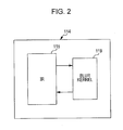
- the reconstruction device 114 further includes an iterative reconstruction (IR) unit 118 and a blur kernel 119 in lieu of having a separate resolution improvement device 117.
- IR iterative reconstruction
- the blur kernel 119 substantially improves the spatial resolution as the iterative reconstruction unit 118 iteratively reconstructs the images.
- the blur kernel 119 substantially improves the spatial resolution using a spatially variant low pass filter that is also angular sensitive.
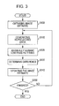
- a flow chart illustrates steps involved in one process of substantially improving spatial resolution in iteratively reconstructing images according to the current embodiment.
- the exemplary process substantially improves spatial resolution as the images are iteratively reconstructed by applying a spatially variant low pass filter that is also angular sensitive.
- an image estimate for example, an image based upon projection data (first projection data) that is obtained by an imaging (a measurement)
- the image estimate is forward projected using at least a single ray to generate reprojected data.
- a combination of the system optics is optionally taken into account.
- the system optics includes a focal spot size, a detector size and an image voxel size.
- the image voxel size is not enlarged in one exemplary process of substantially improving spatial resolution in iteratively reconstructing images according to the current embodiment.
- a predetermined angularly variant low pass filter is applied to the reprojected data to generate processed data.
- the angularly variant low pass filter is a low pass filter which varies the filter coefficient (the filter characteristic) corresponding to variation of the fan angle.)
- a difference is determined between the processed data (that is second projection data obtained by a forward projection) of the step S120 and the measured data (that is first projection data obtained by the imaging) as used in the step S100. Consequently, the image estimate is updated based upon the difference as determined in the step S130 to generate an updated image in a step S140.
- the exemplary IR process according to the current embodiment iterates the steps S110 through S140 using the updated image as the image estimate in the step S110 for a predetermined number of times or until a predetermined condition is satisfied in a step S150. That is, the step S150 determines as to whether or not the exemplary IR process continues the iteration or finishes according to the current embodiment.
- the system optics blur is overestimated in order to sharpen the images in certain situations.
- IR acts as a deconvolution and substantially overcomes the limitations of the system optics such as a focal spot size and a detector element size. That is, a system blur kernel is simulated in the forward projection in order to improve spatial resolution.
- images are substantially improved in spatial resolution by applying to the reprojected data at least an angularly variant low pass filter to generate processed data in a step S120.
- the angularly variant low pass filter in the step S120 is an example of the system blur kernel and optionally includes other additional variable components such as distance in combination with angle to affect the low pass filter characteristics.
- the above exemplary IR process of substantially improving spatial resolution improves diagnostic values in clinical CT applications such as imaging of the lungs and coronary computed tomography angiogram (CTA) where a high degree of spatial resolution is required.
- CTA coronary computed tomography angiogram
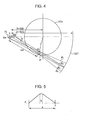
- FIGURE 4 a diagram illustrates certain characteristics of one exemplary focal spot in relation to an image pixel and a detector according to the current embodiment.
- a focal spot FS and a detector array DET are placed at a certain position with respect to an image pixel IP in a field of view FOV.
- the focal spot FS is projected as a relatively thin strip or width dsx on the detector DET as indicated by a dotted line at one angle.
- the focal spot FS is projected as a relatively elongated strip dsy on the detector DET as indicated by solid lines going through the image pixel IP at another angle.
- FIGURE 5 a diagram illustrates certain characteristics of one example of the angle-dependent spatially variant low pass filter according to the current embodiment.
- the characteristics of the angle-dependent spatially variant low pass filter are described with respect to the exemplary focal spot in relation to an image pixel and a detector as depicted in FIGURE 4 .
- the characteristics of the angle-dependent spatially variant low pass filter is characterized by a base a and a plateau b, which define the blur kernel size.
- the base a is a range of the filter as indicated by a double-headed arrow while the plateau b is a partial domain at the max value of the filter as indicated by a pair of dotted lines, and the both are represented as the following equations (1) and (2), for example.
- a D - S / 2 ⁇ ⁇ 4 - D + S / 2 ⁇ ⁇ 1
- D is a distance between the focal spot FS and the detector DET while S is an effective source size at a specific angle ⁇ as shown in FIGURE 4 .
- ⁇ is the channel angle.
- dsx is 1 mm while dsy is 7mm.
- ⁇ sx R cos ⁇
- ⁇ sx distance from the focal spot.
- a pixel is determined by the parameters ( ⁇ sx , ⁇ ).
- ⁇ 1 , ⁇ 2 , ⁇ 3 , and ⁇ 4 can be represented as the following equations (3) through (6).
- R is a distance from the field of view FOV center to the focal spot FS center as also shown in FIGURE 4 .
- the effects of one exemplary angle-dependent spatially variant low pass filter are dependent on spatial variables including the angles according to the current embodiment.
- the angularly variant blur kernel is computed based upon true focal spot geometry such as elongation and tilt in another embodiment.
- FIGURES 6A through 6C the effects of one exemplary angle-dependent spatially variant low pass filter in the iterative reconstruction technique according to the current embodiment are compared to other reconstruction techniques.
- FBP filtered-back-projection
- FIGURE 6A illustrates the spatial resolution of predetermined stripes at certain exposures (300 milliampere per second (mAs) and 90 mAs) using a standard kernel (FBP-ST).
- FIGURE 6B illustrates the spatial resolution of the same predetermined stripes at certain exposures (300 mAs and 90 mAs) using a sharp convolution kernel with high-frequency boost (FBP-HR).
- FIGURE 6C illustrates the spatial resolution of the same predetermined stripes at certain exposures (300 mAs and 90 mAs) using one exemplary angle-dependent spatially variant low pass filter in the iterative reconstruction (IR) technique according to the current embodiment.
- IR iterative reconstruction
- the spatial resolution of the same predetermined stripes has substantially improved at both exposures using one exemplary angle-dependent spatially variant low pass filter in the iterative reconstruction technique according to the current embodiment as illustrated in FIGURE 6C .
- a noise level appears substantially lower in 300 mAs while the spatial resolution has substantially improved by the exemplary angle-dependent spatially variant low pass filter in the iterative reconstruction technique according to the current embodiment.
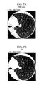
- FIGURE 7A illustrates the spatial resolution of a lung image using a filtered-back-projection (FBP) technique.
- FIGURE 7B illustrates the spatial resolution of the same lung image using one exemplary angle-dependent spatially variant low pass filter in the iterative reconstruction (IR) technique according to the current embodiment.
- FBP filtered-back-projection
- IR iterative reconstruction
- FIGURES 8A and 8B the effects of one exemplary angle-dependent spatially variant low pass filter in the iterative reconstruction technique according to the current embodiment are compared to other reconstruction techniques.
- FBP filtered-back-projection
- FIGURE 8A illustrates a noise level over a predetermined exposure range as the spatial resolution is improved among a standard kernel (FBP-ST), a sharp convolution kernel with high-frequency boost (FBP-HR) and one exemplary angle-dependent spatially variant low pass filter in the iterative reconstruction (IR) technique according to the current embodiment.
- the FBP-ST has the lowest noise level across the exposure range, the spatial resolution is also lower in comparison to other techniques.
- the FBP-HR and IR techniques both have a substantially improve level of spatial resolution in the reconstructed image, both the FBP-HR and IR techniques also have a higher level of noise across the exposure range.
- the comparison of the FBP-HR and IR techniques reveals that the IR technique according to the current embodiment yields a lower noise level than the FBP-HR technique across the entire exposure range.
- FIGURE 8B illustrates modulation to noise ratios over a predetermined exposure range as the spatial resolution is improved among a standard kernel (FBP-ST), a sharp convolution kernel with high-frequency boost (FBP-HR) and one exemplary angle-dependent spatially variant low pass filter in the iterative reconstruction (IR) technique according to the current embodiment.
- FBP-ST has the lowest modulation to noise ratio across the exposure range
- the spatial resolution is also lower in comparison to other techniques.
- the FBP-HR and IR techniques both have a substantially improve level of spatial resolution in the reconstructed image, and both the FBP-HR and IR techniques also have a higher modulation value to noise ratio across the exposure range.
- the comparison of the FBP-HR and IR techniques reveals that the IR technique according to the current embodiment yields a substantially higher modulation to noise ratio than the FBP-HR technique across the entire exposure range.
- an angularly variant low pass filter a case of using a low pass filter which varies a filter coefficient corresponding to variance of a fan angle is illustrated in the above embodiment. It is not necessary to be restricted to the example, however, as an angularly variant low pass filter, a low pass filter which varies a filter coefficient corresponding to variance of a cone angle, or to at least one of variance of a cone angle or a fan angle, for example.
Landscapes
- Physics & Mathematics (AREA)
- General Physics & Mathematics (AREA)
- Engineering & Computer Science (AREA)
- Theoretical Computer Science (AREA)
- Apparatus For Radiation Diagnosis (AREA)
- Image Processing (AREA)
Applications Claiming Priority (2)
| Application Number | Priority Date | Filing Date | Title |
|---|---|---|---|
| US13/347,398 US8837797B2 (en) | 2012-01-10 | 2012-01-10 | Spatial resolution improvement in computer tomography (CT) using iterative reconstruction |
| PCT/JP2013/050240 WO2013105583A1 (fr) | 2012-01-10 | 2013-01-09 | Dispositif de tomographie à rayons x (dispositif ct à rayons x) utilisant des approximations successives |
Publications (2)
| Publication Number | Publication Date |
|---|---|
| EP2803320A1 true EP2803320A1 (fr) | 2014-11-19 |
| EP2803320A4 EP2803320A4 (fr) | 2016-08-03 |
Family
ID=48743968
Family Applications (1)
| Application Number | Title | Priority Date | Filing Date |
|---|---|---|---|
| EP13736045.9A Withdrawn EP2803320A4 (fr) | 2012-01-10 | 2013-01-09 | Dispositif de tomographie à rayons x (dispositif ct à rayons x) utilisant des approximations successives |
Country Status (5)
| Country | Link |
|---|---|
| US (1) | US8837797B2 (fr) |
| EP (1) | EP2803320A4 (fr) |
| JP (1) | JP6062250B2 (fr) |
| CN (1) | CN104039233B (fr) |
| WO (1) | WO2013105583A1 (fr) |
Families Citing this family (9)
| Publication number | Priority date | Publication date | Assignee | Title |
|---|---|---|---|---|
| US8885903B2 (en) * | 2011-11-16 | 2014-11-11 | General Electric Company | Method and apparatus for statistical iterative reconstruction |
| JP6161003B2 (ja) * | 2013-11-11 | 2017-07-12 | 東芝Itコントロールシステム株式会社 | プログラム、再構成装置及び断層撮影装置 |
| CN104408753B (zh) * | 2014-10-27 | 2017-04-12 | 浙江大学 | 锥束ct的自适应迭代散射修正方法 |
| US10417795B2 (en) * | 2015-04-08 | 2019-09-17 | Canon Medical Systems Corporation | Iterative reconstruction with system optics modeling using filters |
| JP6414236B2 (ja) | 2017-01-12 | 2018-10-31 | オムロン株式会社 | 画像処理装置及び画像処理方法 |
| JP7046543B2 (ja) * | 2017-09-27 | 2022-04-04 | 浜松ホトニクス株式会社 | 断層画像撮影装置及び断層画像撮影方法 |
| WO2019230740A1 (fr) * | 2018-05-28 | 2019-12-05 | 国立研究開発法人理化学研究所 | Procédé et dispositif d'acquisition de données d'image tomographique par suréchantillonnage et programme de commande |
| WO2019230741A1 (fr) | 2018-05-28 | 2019-12-05 | 国立研究開発法人理化学研究所 | Procédé d'acquisition, dispositif d'acquisition et programme pour données d'image tomographique au moyen d'un décalage angulaire |
| EP4283343B1 (fr) | 2021-01-21 | 2026-04-15 | Riken | Système, procédé et programme d'imagerie tomographique, et support d'enregistrement dans lequel un programme est enregistré |
Family Cites Families (16)
| Publication number | Priority date | Publication date | Assignee | Title |
|---|---|---|---|---|
| JPS6385480A (ja) * | 1986-09-30 | 1988-04-15 | Shimadzu Corp | 投影装置 |
| US6917663B2 (en) * | 2003-06-16 | 2005-07-12 | Kabushiki Kaisha Toshiba | Cone-beam reconstruction apparatus and computed tomography apparatus |
| JP4535795B2 (ja) * | 2004-07-12 | 2010-09-01 | ジーイー・メディカル・システムズ・グローバル・テクノロジー・カンパニー・エルエルシー | 画像処理装置及びx線ctシステム |
| US7424088B2 (en) * | 2004-09-29 | 2008-09-09 | Kabushiki Kaisha Toshiba | Image reconstruction method using Hilbert transform |
| US7251306B2 (en) * | 2004-11-17 | 2007-07-31 | General Electric Company | Methods, apparatus, and software to facilitate iterative reconstruction of images |
| CN1640361A (zh) * | 2005-01-06 | 2005-07-20 | 东南大学 | 多相水平集的正电子断层扫描重建方法 |
| CN103824266B (zh) * | 2005-09-26 | 2017-06-16 | 皇家飞利浦电子股份有限公司 | 具有增强噪声控制滤波的迭代重建 |
| US7583780B2 (en) * | 2006-06-22 | 2009-09-01 | General Electric Company | Systems and methods for improving a resolution of an image |
| JP5280450B2 (ja) * | 2008-08-07 | 2013-09-04 | 株式会社日立メディコ | X線ct画像形成方法及びそれを用いたx線ct装置 |
| US8655033B2 (en) | 2009-10-28 | 2014-02-18 | General Electric Company | Iterative reconstruction |
| US20110164031A1 (en) * | 2010-01-06 | 2011-07-07 | Kabushiki Kaisha Toshiba | Novel implementation of total variation (tv) minimization iterative reconstruction algorithm suitable for parallel computation |
| JP5960048B2 (ja) * | 2010-03-30 | 2016-08-02 | 株式会社日立製作所 | 再構成演算装置、再構成演算方法、及びx線ct装置 |
| US8478013B2 (en) * | 2010-05-25 | 2013-07-02 | Kabushiki Kaisha Toshiba | Automatic motion map generation in helical CT |
| US8615118B2 (en) * | 2010-05-28 | 2013-12-24 | The University Of Maryland, Baltimore | Techniques for tomographic image by background subtraction |
| RU2575981C2 (ru) * | 2010-06-21 | 2016-02-27 | АЙМАКС Юроп СА | Проекция с двойным наложением |
| US8903150B2 (en) * | 2011-07-31 | 2014-12-02 | Varian Medical Systems, Inc. | Filtration imaging enhancement method and system |
-
2012
- 2012-01-10 US US13/347,398 patent/US8837797B2/en active Active
-
2013
- 2013-01-09 WO PCT/JP2013/050240 patent/WO2013105583A1/fr not_active Ceased
- 2013-01-09 EP EP13736045.9A patent/EP2803320A4/fr not_active Withdrawn
- 2013-01-09 CN CN201380005108.3A patent/CN104039233B/zh active Active
- 2013-01-10 JP JP2013002456A patent/JP6062250B2/ja active Active
Also Published As
| Publication number | Publication date |
|---|---|
| CN104039233A (zh) | 2014-09-10 |
| WO2013105583A1 (fr) | 2013-07-18 |
| EP2803320A4 (fr) | 2016-08-03 |
| JP2013141608A (ja) | 2013-07-22 |
| CN104039233B (zh) | 2016-10-12 |
| JP6062250B2 (ja) | 2017-01-18 |
| US8837797B2 (en) | 2014-09-16 |
| US20130177225A1 (en) | 2013-07-11 |
Similar Documents
| Publication | Publication Date | Title |
|---|---|---|
| EP2803320A1 (fr) | Dispositif de tomographie à rayons x (dispositif ct à rayons x) utilisant des approximations successives | |
| US8965078B2 (en) | Projection-space denoising with bilateral filtering in computed tomography | |
| US8731269B2 (en) | Method and system for substantially reducing artifacts in circular cone beam computer tomography (CT) | |
| JP6956505B2 (ja) | 画像処理装置、x線ct装置及び画像処理方法 | |
| JP6139092B2 (ja) | X線ct装置およびシステム | |
| US10789738B2 (en) | Method and apparatus to reduce artifacts in a computed-tomography (CT) image by iterative reconstruction (IR) using a cost function with a de-emphasis operator | |
| US10111638B2 (en) | Apparatus and method for registration and reprojection-based material decomposition for spectrally resolved computed tomography | |
| CN103054600B (zh) | X射线ct装置、医用图像处理装置及医用图像处理方法 | |
| US20130202080A1 (en) | System and Method for Denoising Medical Images Adaptive to Local Noise | |
| JP2010527741A (ja) | 画像再構成において利得変動の補正を容易にする方法及びシステム | |
| US9076237B2 (en) | System and method for estimating a statistical noise map in x-ray imaging applications | |
| RU2598159C2 (ru) | Способ реконструкции изображений для отфильтрованной обратной проекции в томографии с ограниченным углом обзора объекта | |
| JP6222813B2 (ja) | X線コンピュータ断層撮影装置、画像処理装置及び画像処理方法 | |
| US9704223B2 (en) | Method and system for substantially reducing cone beam artifacts based upon adaptive scaling factor in circular computer tomography (CT) | |
| JP6878147B2 (ja) | X線コンピュータ断層撮影装置及び医用画像処理装置 | |
| JP7187131B2 (ja) | 画像生成装置、x線コンピュータ断層撮影装置及び画像生成方法 | |
| US8385620B2 (en) | Method and system for multi-detector-row computed tomography utilizing projection data up-sampling with shift | |
| WO2022096401A1 (fr) | Procédés et systèmes de génération d'une image de tomodensitométrie spectrale | |
| US9558569B2 (en) | Method and system for substantially reducing cone beam artifacts based upon image domain differentiation in circular computer tomography (CT) | |
| JP4387758B2 (ja) | Spect装置及びspect画像再構成方法 | |
| US11967005B2 (en) | Cone beam artifact correction for gated imaging | |
| US12530825B2 (en) | Method and apparatus for scatter estimation in computed tomography imaging systems |
Legal Events
| Date | Code | Title | Description |
|---|---|---|---|
| PUAI | Public reference made under article 153(3) epc to a published international application that has entered the european phase |
Free format text: ORIGINAL CODE: 0009012 |
|
| 17P | Request for examination filed |
Effective date: 20140808 |
|
| AK | Designated contracting states |
Kind code of ref document: A1 Designated state(s): AL AT BE BG CH CY CZ DE DK EE ES FI FR GB GR HR HU IE IS IT LI LT LU LV MC MK MT NL NO PL PT RO RS SE SI SK SM TR |
|
| DAX | Request for extension of the european patent (deleted) | ||
| RA4 | Supplementary search report drawn up and despatched (corrected) |
Effective date: 20160705 |
|
| RIC1 | Information provided on ipc code assigned before grant |
Ipc: G06T 11/00 20060101AFI20160630BHEP Ipc: A61B 6/03 20060101ALI20160630BHEP |
|
| RAP1 | Party data changed (applicant data changed or rights of an application transferred) |
Owner name: TOSHIBA MEDICAL SYSTEMS CORPORATION |
|
| STAA | Information on the status of an ep patent application or granted ep patent |
Free format text: STATUS: EXAMINATION IS IN PROGRESS |
|
| 17Q | First examination report despatched |
Effective date: 20180727 |
|
| STAA | Information on the status of an ep patent application or granted ep patent |
Free format text: STATUS: THE APPLICATION HAS BEEN WITHDRAWN |
|
| 18W | Application withdrawn |
Effective date: 20190206 |