EP2803339B1 - Medizinischer Stent - Google Patents
Medizinischer Stent Download PDFInfo
- Publication number
- EP2803339B1 EP2803339B1 EP14172081.3A EP14172081A EP2803339B1 EP 2803339 B1 EP2803339 B1 EP 2803339B1 EP 14172081 A EP14172081 A EP 14172081A EP 2803339 B1 EP2803339 B1 EP 2803339B1
- Authority
- EP
- European Patent Office
- Prior art keywords
- stent
- coil
- coil part
- marker
- marker coil
- Prior art date
- Legal status (The legal status is an assumption and is not a legal conclusion. Google has not performed a legal analysis and makes no representation as to the accuracy of the status listed.)
- Not-in-force
Links
- 239000003550 marker Substances 0.000 claims description 89
- 238000005452 bending Methods 0.000 claims description 63
- 229920005989 resin Polymers 0.000 claims description 22
- 239000011347 resin Substances 0.000 claims description 22
- 239000000463 material Substances 0.000 claims description 20
- 238000004804 winding Methods 0.000 claims description 18
- 230000002093 peripheral effect Effects 0.000 claims description 15
- 208000027418 Wounds and injury Diseases 0.000 description 72
- 210000000013 bile duct Anatomy 0.000 description 45
- 239000011295 pitch Substances 0.000 description 41
- 208000031481 Pathologic Constriction Diseases 0.000 description 31
- 238000012360 testing method Methods 0.000 description 16
- 229920001971 elastomer Polymers 0.000 description 13
- 239000000806 elastomer Substances 0.000 description 13
- 238000000034 method Methods 0.000 description 12
- 238000010586 diagram Methods 0.000 description 11
- 230000002183 duodenal effect Effects 0.000 description 9
- 230000004048 modification Effects 0.000 description 7
- 238000012986 modification Methods 0.000 description 7
- 229920003225 polyurethane elastomer Polymers 0.000 description 6
- 239000004698 Polyethylene Substances 0.000 description 5
- 210000000941 bile Anatomy 0.000 description 5
- 239000002872 contrast media Substances 0.000 description 5
- 238000003384 imaging method Methods 0.000 description 5
- -1 polyethylene Polymers 0.000 description 5
- 229920000573 polyethylene Polymers 0.000 description 5
- 239000004952 Polyamide Substances 0.000 description 4
- 239000004793 Polystyrene Substances 0.000 description 4
- 230000009477 glass transition Effects 0.000 description 4
- 229920002647 polyamide Polymers 0.000 description 4
- 229920002223 polystyrene Polymers 0.000 description 4
- 230000008859 change Effects 0.000 description 3
- 230000007423 decrease Effects 0.000 description 3
- 230000006866 deterioration Effects 0.000 description 3
- 210000001198 duodenum Anatomy 0.000 description 3
- 230000000694 effects Effects 0.000 description 3
- 229910052751 metal Inorganic materials 0.000 description 3
- 239000002184 metal Substances 0.000 description 3
- 229920000728 polyester Polymers 0.000 description 3
- 230000003014 reinforcing effect Effects 0.000 description 3
- 206010028980 Neoplasm Diseases 0.000 description 2
- 208000025865 Ulcer Diseases 0.000 description 2
- 201000011510 cancer Diseases 0.000 description 2
- 230000000052 comparative effect Effects 0.000 description 2
- 238000005520 cutting process Methods 0.000 description 2
- 230000009545 invasion Effects 0.000 description 2
- 230000014759 maintenance of location Effects 0.000 description 2
- 230000005012 migration Effects 0.000 description 2
- 238000013508 migration Methods 0.000 description 2
- 210000004877 mucosa Anatomy 0.000 description 2
- 229920011301 perfluoro alkoxyl alkane Polymers 0.000 description 2
- 229920003023 plastic Polymers 0.000 description 2
- 239000004033 plastic Substances 0.000 description 2
- 230000036269 ulceration Effects 0.000 description 2
- 235000009854 Cucurbita moschata Nutrition 0.000 description 1
- 240000001980 Cucurbita pepo Species 0.000 description 1
- 235000009852 Cucurbita pepo Nutrition 0.000 description 1
- 208000036828 Device occlusion Diseases 0.000 description 1
- YCKRFDGAMUMZLT-UHFFFAOYSA-N Fluorine atom Chemical compound [F] YCKRFDGAMUMZLT-UHFFFAOYSA-N 0.000 description 1
- 208000004221 Multiple Trauma Diseases 0.000 description 1
- 229910000831 Steel Inorganic materials 0.000 description 1
- 239000000654 additive Substances 0.000 description 1
- 230000000996 additive effect Effects 0.000 description 1
- 210000004204 blood vessel Anatomy 0.000 description 1
- 230000036760 body temperature Effects 0.000 description 1
- 230000006835 compression Effects 0.000 description 1
- 238000007906 compression Methods 0.000 description 1
- 235000008504 concentrate Nutrition 0.000 description 1
- 239000012141 concentrate Substances 0.000 description 1
- 239000000470 constituent Substances 0.000 description 1
- 210000000981 epithelium Anatomy 0.000 description 1
- 229910052731 fluorine Inorganic materials 0.000 description 1
- 239000011737 fluorine Substances 0.000 description 1
- 210000001035 gastrointestinal tract Anatomy 0.000 description 1
- 238000003780 insertion Methods 0.000 description 1
- 230000037431 insertion Effects 0.000 description 1
- 210000004185 liver Anatomy 0.000 description 1
- 230000033001 locomotion Effects 0.000 description 1
- 230000007774 longterm Effects 0.000 description 1
- 210000000277 pancreatic duct Anatomy 0.000 description 1
- 229920013716 polyethylene resin Polymers 0.000 description 1
- 239000004810 polytetrafluoroethylene Substances 0.000 description 1
- 229920001343 polytetrafluoroethylene Polymers 0.000 description 1
- 238000003825 pressing Methods 0.000 description 1
- 230000009467 reduction Effects 0.000 description 1
- 238000004904 shortening Methods 0.000 description 1
- 239000007779 soft material Substances 0.000 description 1
- 238000005476 soldering Methods 0.000 description 1
- 235000020354 squash Nutrition 0.000 description 1
- 229910001220 stainless steel Inorganic materials 0.000 description 1
- 239000010935 stainless steel Substances 0.000 description 1
- 239000010959 steel Substances 0.000 description 1
- 239000000126 substance Substances 0.000 description 1
- 210000001519 tissue Anatomy 0.000 description 1
- WFKWXMTUELFFGS-UHFFFAOYSA-N tungsten Chemical compound [W] WFKWXMTUELFFGS-UHFFFAOYSA-N 0.000 description 1
- 229910052721 tungsten Inorganic materials 0.000 description 1
- 239000010937 tungsten Substances 0.000 description 1
- 230000002485 urinary effect Effects 0.000 description 1
- 238000003466 welding Methods 0.000 description 1
Images


Classifications
-
- A—HUMAN NECESSITIES
- A61—MEDICAL OR VETERINARY SCIENCE; HYGIENE
- A61F—FILTERS IMPLANTABLE INTO BLOOD VESSELS; PROSTHESES; DEVICES PROVIDING PATENCY TO, OR PREVENTING COLLAPSING OF, TUBULAR STRUCTURES OF THE BODY, e.g. STENTS; ORTHOPAEDIC, NURSING OR CONTRACEPTIVE DEVICES; FOMENTATION; TREATMENT OR PROTECTION OF EYES OR EARS; BANDAGES, DRESSINGS OR ABSORBENT PADS; FIRST-AID KITS
- A61F2/00—Filters implantable into blood vessels; Prostheses, i.e. artificial substitutes or replacements for parts of the body; Appliances for connecting them with the body; Devices providing patency to, or preventing collapsing of, tubular structures of the body, e.g. stents
- A61F2/82—Devices providing patency to, or preventing collapsing of, tubular structures of the body, e.g. stents
- A61F2/86—Stents in a form characterised by the wire-like elements; Stents in the form characterised by a net-like or mesh-like structure
- A61F2/88—Stents in a form characterised by the wire-like elements; Stents in the form characterised by a net-like or mesh-like structure the wire-like elements formed as helical or spiral coils
-
- A—HUMAN NECESSITIES
- A61—MEDICAL OR VETERINARY SCIENCE; HYGIENE
- A61F—FILTERS IMPLANTABLE INTO BLOOD VESSELS; PROSTHESES; DEVICES PROVIDING PATENCY TO, OR PREVENTING COLLAPSING OF, TUBULAR STRUCTURES OF THE BODY, e.g. STENTS; ORTHOPAEDIC, NURSING OR CONTRACEPTIVE DEVICES; FOMENTATION; TREATMENT OR PROTECTION OF EYES OR EARS; BANDAGES, DRESSINGS OR ABSORBENT PADS; FIRST-AID KITS
- A61F2/00—Filters implantable into blood vessels; Prostheses, i.e. artificial substitutes or replacements for parts of the body; Appliances for connecting them with the body; Devices providing patency to, or preventing collapsing of, tubular structures of the body, e.g. stents
- A61F2/02—Prostheses implantable into the body
- A61F2/04—Hollow or tubular parts of organs, e.g. bladders, tracheae, bronchi or bile ducts
-
- A—HUMAN NECESSITIES
- A61—MEDICAL OR VETERINARY SCIENCE; HYGIENE
- A61F—FILTERS IMPLANTABLE INTO BLOOD VESSELS; PROSTHESES; DEVICES PROVIDING PATENCY TO, OR PREVENTING COLLAPSING OF, TUBULAR STRUCTURES OF THE BODY, e.g. STENTS; ORTHOPAEDIC, NURSING OR CONTRACEPTIVE DEVICES; FOMENTATION; TREATMENT OR PROTECTION OF EYES OR EARS; BANDAGES, DRESSINGS OR ABSORBENT PADS; FIRST-AID KITS
- A61F2/00—Filters implantable into blood vessels; Prostheses, i.e. artificial substitutes or replacements for parts of the body; Appliances for connecting them with the body; Devices providing patency to, or preventing collapsing of, tubular structures of the body, e.g. stents
- A61F2/82—Devices providing patency to, or preventing collapsing of, tubular structures of the body, e.g. stents
- A61F2/94—Stents retaining their form, i.e. not being deformable, after placement in the predetermined place
-
- A—HUMAN NECESSITIES
- A61—MEDICAL OR VETERINARY SCIENCE; HYGIENE
- A61M—DEVICES FOR INTRODUCING MEDIA INTO, OR ONTO, THE BODY; DEVICES FOR TRANSDUCING BODY MEDIA OR FOR TAKING MEDIA FROM THE BODY; DEVICES FOR PRODUCING OR ENDING SLEEP OR STUPOR
- A61M27/00—Drainage appliance for wounds or the like, i.e. wound drains, implanted drains
- A61M27/002—Implant devices for drainage of body fluids from one part of the body to another
- A61M27/008—Implant devices for drainage of body fluids from one part of the body to another pre-shaped, for use in the urethral or ureteral tract
-
- A—HUMAN NECESSITIES
- A61—MEDICAL OR VETERINARY SCIENCE; HYGIENE
- A61F—FILTERS IMPLANTABLE INTO BLOOD VESSELS; PROSTHESES; DEVICES PROVIDING PATENCY TO, OR PREVENTING COLLAPSING OF, TUBULAR STRUCTURES OF THE BODY, e.g. STENTS; ORTHOPAEDIC, NURSING OR CONTRACEPTIVE DEVICES; FOMENTATION; TREATMENT OR PROTECTION OF EYES OR EARS; BANDAGES, DRESSINGS OR ABSORBENT PADS; FIRST-AID KITS
- A61F2/00—Filters implantable into blood vessels; Prostheses, i.e. artificial substitutes or replacements for parts of the body; Appliances for connecting them with the body; Devices providing patency to, or preventing collapsing of, tubular structures of the body, e.g. stents
- A61F2/02—Prostheses implantable into the body
- A61F2/04—Hollow or tubular parts of organs, e.g. bladders, tracheae, bronchi or bile ducts
- A61F2002/041—Bile ducts
-
- A—HUMAN NECESSITIES
- A61—MEDICAL OR VETERINARY SCIENCE; HYGIENE
- A61F—FILTERS IMPLANTABLE INTO BLOOD VESSELS; PROSTHESES; DEVICES PROVIDING PATENCY TO, OR PREVENTING COLLAPSING OF, TUBULAR STRUCTURES OF THE BODY, e.g. STENTS; ORTHOPAEDIC, NURSING OR CONTRACEPTIVE DEVICES; FOMENTATION; TREATMENT OR PROTECTION OF EYES OR EARS; BANDAGES, DRESSINGS OR ABSORBENT PADS; FIRST-AID KITS
- A61F2/00—Filters implantable into blood vessels; Prostheses, i.e. artificial substitutes or replacements for parts of the body; Appliances for connecting them with the body; Devices providing patency to, or preventing collapsing of, tubular structures of the body, e.g. stents
- A61F2/02—Prostheses implantable into the body
- A61F2/04—Hollow or tubular parts of organs, e.g. bladders, tracheae, bronchi or bile ducts
- A61F2002/047—Urethrae
-
- A—HUMAN NECESSITIES
- A61—MEDICAL OR VETERINARY SCIENCE; HYGIENE
- A61F—FILTERS IMPLANTABLE INTO BLOOD VESSELS; PROSTHESES; DEVICES PROVIDING PATENCY TO, OR PREVENTING COLLAPSING OF, TUBULAR STRUCTURES OF THE BODY, e.g. STENTS; ORTHOPAEDIC, NURSING OR CONTRACEPTIVE DEVICES; FOMENTATION; TREATMENT OR PROTECTION OF EYES OR EARS; BANDAGES, DRESSINGS OR ABSORBENT PADS; FIRST-AID KITS
- A61F2210/00—Particular material properties of prostheses classified in groups A61F2/00 - A61F2/26 or A61F2/82 or A61F9/00 or A61F11/00 or subgroups thereof
- A61F2210/0076—Particular material properties of prostheses classified in groups A61F2/00 - A61F2/26 or A61F2/82 or A61F9/00 or A61F11/00 or subgroups thereof multilayered, e.g. laminated structures
-
- A—HUMAN NECESSITIES
- A61—MEDICAL OR VETERINARY SCIENCE; HYGIENE
- A61F—FILTERS IMPLANTABLE INTO BLOOD VESSELS; PROSTHESES; DEVICES PROVIDING PATENCY TO, OR PREVENTING COLLAPSING OF, TUBULAR STRUCTURES OF THE BODY, e.g. STENTS; ORTHOPAEDIC, NURSING OR CONTRACEPTIVE DEVICES; FOMENTATION; TREATMENT OR PROTECTION OF EYES OR EARS; BANDAGES, DRESSINGS OR ABSORBENT PADS; FIRST-AID KITS
- A61F2220/00—Fixations or connections for prostheses classified in groups A61F2/00 - A61F2/26 or A61F2/82 or A61F9/00 or A61F11/00 or subgroups thereof
- A61F2220/0008—Fixation appliances for connecting prostheses to the body
- A61F2220/0016—Fixation appliances for connecting prostheses to the body with sharp anchoring protrusions, e.g. barbs, pins, spikes
-
- A—HUMAN NECESSITIES
- A61—MEDICAL OR VETERINARY SCIENCE; HYGIENE
- A61F—FILTERS IMPLANTABLE INTO BLOOD VESSELS; PROSTHESES; DEVICES PROVIDING PATENCY TO, OR PREVENTING COLLAPSING OF, TUBULAR STRUCTURES OF THE BODY, e.g. STENTS; ORTHOPAEDIC, NURSING OR CONTRACEPTIVE DEVICES; FOMENTATION; TREATMENT OR PROTECTION OF EYES OR EARS; BANDAGES, DRESSINGS OR ABSORBENT PADS; FIRST-AID KITS
- A61F2250/00—Special features of prostheses classified in groups A61F2/00 - A61F2/26 or A61F2/82 or A61F9/00 or A61F11/00 or subgroups thereof
- A61F2250/0014—Special features of prostheses classified in groups A61F2/00 - A61F2/26 or A61F2/82 or A61F9/00 or A61F11/00 or subgroups thereof having different values of a given property or geometrical feature, e.g. mechanical property or material property, at different locations within the same prosthesis
- A61F2250/0032—Special features of prostheses classified in groups A61F2/00 - A61F2/26 or A61F2/82 or A61F9/00 or A61F11/00 or subgroups thereof having different values of a given property or geometrical feature, e.g. mechanical property or material property, at different locations within the same prosthesis differing in radiographic density
-
- A—HUMAN NECESSITIES
- A61—MEDICAL OR VETERINARY SCIENCE; HYGIENE
- A61F—FILTERS IMPLANTABLE INTO BLOOD VESSELS; PROSTHESES; DEVICES PROVIDING PATENCY TO, OR PREVENTING COLLAPSING OF, TUBULAR STRUCTURES OF THE BODY, e.g. STENTS; ORTHOPAEDIC, NURSING OR CONTRACEPTIVE DEVICES; FOMENTATION; TREATMENT OR PROTECTION OF EYES OR EARS; BANDAGES, DRESSINGS OR ABSORBENT PADS; FIRST-AID KITS
- A61F2250/00—Special features of prostheses classified in groups A61F2/00 - A61F2/26 or A61F2/82 or A61F9/00 or A61F11/00 or subgroups thereof
- A61F2250/0058—Additional features; Implant or prostheses properties not otherwise provided for
- A61F2250/0096—Markers and sensors for detecting a position or changes of a position of an implant, e.g. RF sensors, ultrasound markers
- A61F2250/0098—Markers and sensors for detecting a position or changes of a position of an implant, e.g. RF sensors, ultrasound markers radio-opaque, e.g. radio-opaque markers
-
- A—HUMAN NECESSITIES
- A61—MEDICAL OR VETERINARY SCIENCE; HYGIENE
- A61M—DEVICES FOR INTRODUCING MEDIA INTO, OR ONTO, THE BODY; DEVICES FOR TRANSDUCING BODY MEDIA OR FOR TAKING MEDIA FROM THE BODY; DEVICES FOR PRODUCING OR ENDING SLEEP OR STUPOR
- A61M25/00—Catheters; Hollow probes
- A61M25/0043—Catheters; Hollow probes characterised by structural features
- A61M25/005—Catheters; Hollow probes characterised by structural features with embedded materials for reinforcement, e.g. wires, coils, braids
- A61M25/0052—Localized reinforcement, e.g. where only a specific part of the catheter is reinforced, for rapid exchange guidewire port
-
- A—HUMAN NECESSITIES
- A61—MEDICAL OR VETERINARY SCIENCE; HYGIENE
- A61M—DEVICES FOR INTRODUCING MEDIA INTO, OR ONTO, THE BODY; DEVICES FOR TRANSDUCING BODY MEDIA OR FOR TAKING MEDIA FROM THE BODY; DEVICES FOR PRODUCING OR ENDING SLEEP OR STUPOR
- A61M25/00—Catheters; Hollow probes
- A61M25/0043—Catheters; Hollow probes characterised by structural features
- A61M25/005—Catheters; Hollow probes characterised by structural features with embedded materials for reinforcement, e.g. wires, coils, braids
- A61M25/0053—Catheters; Hollow probes characterised by structural features with embedded materials for reinforcement, e.g. wires, coils, braids having a variable stiffness along the longitudinal axis, e.g. by varying the pitch of the coil or braid
Definitions
- the present invention relates to a medical stent.
- Priority is claimed on Japanese Patent Application No. 2010-073817, filed in Japan on March 26, 2010 .
- a medical stent (hereinafter also abbreviated as 'stent') is placed to a stricture in a lumen inside a living body such as a blood vessel, a digestive tract, a bile duct, a pancreatic duct, and a urinary duct, in order to expand this stricture and maintain an open state.
- a stent used in a bile duct such as that shown in Patent Document 1 is substantially tubular. Flaps which open in a natural state and can deform so as to close when a predetermined external force is applied, are provided on the distal-end side and the proximal-end side of this stent. The flaps engage with the entrance to the duodenal papilla and the end of the stricture of the bile duct, thereby preventing the stent from moving to the stricture.
- Characteristics demanded of this type of stent include ease of bending in order to follow the curving shape of the bile duct in the body and the motion of the body, i.e. flexibility, and, at the same time, hardness (lumen-maintaining properties) so that it does not collapse when bent and can maintain the size of its own lumen.
- One of this stent made from a soft resin (e.g. soft polyethylene, polystyrene elastomer, polyamide elastomer, polyester elastomer, polyurethane elastomer, etc.) formed in a tubular shape. While this can enhance the ease of bending of the stent, the thickness of the stent must be increased to prevent it from collapsing in the radial direction. When the thickness of a stent decreases, the minimum required lumen-maintaining properties cannot be maintained. In addition, the stent may be bent by being crushed by a stricture after the stent has been placed inside the body, and by a bile duct being pulled along with the invasion of cancer.
- a soft resin e.g. soft polyethylene, polystyrene elastomer, polyamide elastomer, polyester elastomer, polyurethane elastomer, etc.
- the stent cannot maintain a lumen due to bent or crush. That is to say, draining bile which is an important role of a stent may not be able to be performed. Therefore, a stent is required to lumen-maintaining properties which is at least equivalent to existing products. If the thickness of a stent is wet with giving to the lumen-maintaining properties, the thickness of the stent increases and a flexible stent is not obtained.
- the resisting force sometimes acts as a power which removes the stent from a position where the stent was placed, and then, the stent may move to (wander into) a deep part of a bile duct (liver side) and dropout (deviate) to a duodenum side. In this case, since an additional procedure is required, it strains the patient.
- the resisting force sometimes acts as a power which tries to extend the bent bile duct straight, an unnecessary load may be applied to the bile duct.
- the stent is excessively pressed to an epithelial tissue of the bile duct or a mucosa of the duodenum, thereby ulceration may be formed.
- path through which the bile flows in or flows out is occluded when an opening part both sides of the stent attaches to a tissue or a mucosa, and then, the bile may not flow. In this case, a natural function of the stent cannot be exerted.
- Another of the stent made from soft resin contains a blade which metal wire is woven like a mesh.
- the rigidity of the blade maintains the size of the lumen.
- flexibility of the stent become spoiled and resilient force become stronger.
- a thickness of a part of the blade where the wires are overlapped increases in a radial direction and then, the stent is hardly bent due to a friction of each of the wires. That is to say, at the part where the wires are overlapped, the flexibility of the stent is decayed and the resilient force of the stent becomes stronger.
- the stent is also required viewable under radioscopy. This is because the position of the stent needs to be confirmed by irradiation of X-rays when placing the stent or after placing it. It is important that both ends of the stent are astride the stricture to enable bile to reliably pass there through. In addition, it is important that the flaps on the distal-end side of the stent reliably over the stricture to prevent the stent from moving (migrating, escaping) after it is placed. That is, it is necessary to confirm that the flaps are clearly open above the stricture and are engaging with the stricture. When the stent has migrated into the bile duct, it must be removed while confirming its position under radioscopy.
- the proximal end of the stent is held with holding forceps or the like, whereby the stent is removed and collected. Therefore, in removing the stent, it is necessary that the whole stent can be seen under radioscopy, and that the proximal-end part of the stent can be confirmed clearly. When it is difficult to see the position of the distal end of the stent clearly, it takes an amount of time to hold the stent. Accordingly, the strain to the patient and the stress to the operator is caused due to extending the procedure time.
- the stent In placing the stent, there are cases where a plurality of stents are placed. In that case, it is important in this procedure to know the position of the first stent that was placed. Preferably, it is possible to see the whole stent, or to see its part other than both ends. This is to confirm whether the first stent is moving during subsequent stents procedures. Since a conventional stent does not have the above-described function, the operator performs procedure with seeing both a screen under radioscopy and a scope screen.
- the conventional stent is imparted with an imaging ability by mixing a contrast agent which is radiopaque substance to a resin.
- a contrast agent which is radiopaque substance
- the additive amount of the contrast agent increases, an initial physicality (tension strength, flexibility, the resilient force or the like) and a longer-term physicality decrease.
- the conventional stent when placed in the body in the long term, it may induce material deterioration.
- the lumen of the stent narrows and the outer diameter of it the stent increases. Furthermore, the flexibility of the stent is spoiled and a resilient force become stronger.
- Patent Document 2 proposes a method of using a ring-like member or a plate-like member rounded to a substantially cylindrical shape to partially increase radioscopic visibility.
- the ring-like member or the plate-like member rounded to a substantially cylindrical shape cannot bend into arbitrary shape at arbitrary position, because these member become straight in a length at least when bending bent. Accordingly, the flexibility of the stent is decayed and increase the resilient force, and then, degrades the product performance.
- Patent Document 3 proposes a medical stent made from an inner-layer material, a reinforcing layer, and an outer-layer material, with flaps formed only from the outer-layer.
- the thickness of the flap is thin, the X-ray visibility thereof is weak despite of mixing the contrast agent with a resin, and it is hard to check the vicinity of the flap.
- the present invention has been made in consideration of the above-mentioned problems, and an object of the invention is to provide a medical stent that can maintain the property in which it is easy to bend (having flexibility) and resilient force is weak, and that can prevent the lumen from collapsing when bending bent. Furthermore, another object of the invention is to provide a medical stent in which the imaging ability which is one of the important functions is improved without decaying the flexibility and resilient force of the stent.
- the present invention employs the following means. disclosed in independent claim 1. Where in the following the word invention is used and/or features are presented as optional this should be interpreted in such way that protection is sought for the invention as claimed
- a medical stent comprising a coil formed by winding a wire around an axis, an outer layer formed substantially tubular made from a first resin material, provided on an outer peripheral side of said coil and coaxial to said coil, and an inner layer formed substantially tubular made from a second resin material, provided on an inner peripheral side of said coil and coaxial to said coil.
- said first resin material of said outer layer is one of polyamide elastomer resin, polyethylene elastomer resin, polyethylene resin, polystyrene elastomer, or polyurethane elastomer resin, and in said outer layer, the Shore hardness is 25D or more and 70D or less, and the glass transition temperature is equal to or higher than -40degrees Celsius.
- the flexural module of said outer layer is 5 MPa or more and 700 MPa or less, and the flexural module of said inner layer is 1000 MPa or less.
- the thickness of the stent is 0.20 mm or more and 0.35 mm or less, and, if Y1 is the maximum bending load (N) obtained in a cantilever stiffness test and X1 is the deflection (mm) when said maximum bending load Y1 was applied, indicator A defined by the following equation (1) is 4.0 or less.
- said wire is formed from a radiopaque material
- said coil includes a marker coil part formed by winding said wire around said axis so that it is substantially close-wound, and a normal-wound coil part, which is connected to said marker coil part and is formed by winding said wire around said axis at a pitch that is two times or more and twenty times or less the pitch of said wire around the axis in said marker coil part.
- said wire is formed from a radiopaque material
- a plurality of said coils are provided at difference positions on said axis, and adjacent coils among the plurality of said coils are connected by connection parts formed by wires parallel to said axis.
- the above medical stent further comprising an engaging member, whereof a first end is provided to an outer peripheral face of said outer layer, and whereof a second end extends said axis direction and can open to the outer side in the radius direction of the outer layer, said marker coil part of said coil is provided at a position corresponding to said second end of said engaging member in said axis direction.
- said marker coil part is additionally provided at a position corresponding to said first end of said engaging member in said axis direction, and said normal-wound coil part is connected to both of said marker coil parts.
- the above medical stent further comprising a bending part which is pigtail-shaped and formed at least one end part; and said marker coil part of said coil is provided so that it extends a predetermined length from an end of said bending part.
- the medical stent of the present invention it is possible to maintain the property in which it is easy to bend and resilient force is weak, and to prevent the lumen from collapsing when bending bent. According to the medical stent of the present invention, it is possible to improve the imaging ability without decaying the flexibility and resilient force of the stent.
- a stent according to a first embodiment of the invention will be explained while referring to FIG. 1 to FIG. 9 .
- the stent of this embodiment is placed in a bile duct of a living body by means of a stent delivery catheter or the like used percutaneously.
- a stent delivery catheter or the like used percutaneously.
- the ratios about the thickness or sizes of the constituent elements may differ from the actual sizes to facilitate understanding.
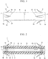
- a stent 1 of this embodiment comprises a coil 3 formed by winding a wire 2 around an axis C1, an outer layer 4 which is formed substantially tubular and provided on the outer peripheral side of the coil 3 and coaxial to the coil 3, and an inner layer 5 which is formed substantially tubular and provided on the inner peripheral side of the coil 3 and is coaxial to the coil 3.
- the wire 2 is made from a metal such as tungsten steel and stainless steel, which is a radiopaque material.
- the wire 2 is circular in cross section. This embodiment uses a wire 2, for example, with an outer diameter of 0.11 mm.
- the wire 2 is wound in a coiled shape around the axis C1 to form the coil 3. If the distance between the cores of the wires 2 which are adjacent to each other in the direction of the axis C1 is treated as the pitch, in this embodiment, the wire 2 is wound at a pitch P1 of approximately 0.41 mm (with an interval between the wires 2 of approximately 0.30 mm).
- the outer layer 4 is made from a polyurethane elastomer resin (first resin material) with a Shore hardness of 70D or less and a glass transition temperature is equal to or higher than -40degrees Celsius, and its nominal outer diameter K is 10 French (3.2 mm, hereinafter 'French' will be abbreviated as 'Fr').
- the outer layer 4 is provided not only on the outer peripheral face of the coil 3 but also in the gaps between the wires 2.
- the flexural module of the outer layer 4 is set at 700 MPa or less.
- the outer layer 4 is made from the polyurethane elastomer resin described above, the material for the outer layer 4 is not limited to this.
- the material for the outer layer 4 can suitably be used, for example, polyamide elastomer, polyethylene elastomer, soft polyethylene, polystyrene elastomer, polyester elastomer, or the like which have a Shore hardness of 70D or less and a glass transition temperature is equal to or higher than -40degrees Celsius.
- the flexural module of the outer layer 4 is 5 MPa or more, and the Shore hardness of the polyurethane elastomer, polyamide elastomer, soft polyethylene, polystyrene elastomer, polyester elastomer is 25D or more.
- biocompatibility the property which suitable for moving inside the body, flexibility and low resilient force
- This has advantageous effects of suppressing migration and deviation of the stent, ulceration and the like, reducing pain for the patient (less invasiveness), etc.
- the inner layer 5 is made from a material (second resin material) which is a fluorine resin and has elasticity, such as PFA (perfluoro alkoxyl alkane), FEP, or PTFE.
- the flexural module of the inner layer 5 is preferably 1000 MPa or less.
- the distance from the outer peripheral face of the outer layer 4 to the inner peripheral face of the inner layer 5, i.e. the thickness D1 of the stent 1, is set at 0.20 mm or more and 0.35 mm or less.
- the thickness of the inner layer 5 is 0.005 mm or more and 0.10 mm or less
- the thickness of the outer layer 4 is 0.07 mm or more and 0.34 mm or less.
- the thickness of the inner layer 5 and the thickness of the outer layer 4 are set with consideration for flexibility, elasticity, the size of the lumen, etc.
- flaps 8-11 are provided at equal angles around an axis C1 (flap 11 is not shown).
- the flaps 8-11 are formed by cutting along a surface of the outer layer4 without cut out and can be open at an end side of a flaps on parts of the distal-end part 4a of the outer layer 4.
- the flaps 8-11 have elasticity, and when they are pressed toward the radially inward side of the outer layer 4, they are stored in notched parts 12-15 respectively (notched part 15 is not shown).
- flaps 16-19 are provided at equal angles around the axis C1 on the outer peripheral face of a proximal-end part 4b of the outer layer 4 (flap 19 is not shown).
- the flaps 16-19 are formed by cutting along a surface of the outer layer 4 without cut out and can be open at an end side of a flaps on parts of the proximal-end part 4b of the outer layer 4.
- the flaps 16-19 are shorter in the direction of the axis C1 than the flaps 8-11.
- the length of the flaps 16-19 is preferably 10 mm or less. If the flaps 16-19 are equal to or longer than 10 mm, it is more difficult for them to pass through the forceps stand, making it more difficult to insert the stent.
- the flaps 16-19 have elasticity, and when the flaps 16-19 are pressed toward the radially inward side of the outer layer 4, they are stored in notched parts 20-23 respectively (notched part 23 is not shown).
- the stent 1 configured in this manner When the stent 1 configured in this manner is placed inside a body, it is important to ensure the resistance to collapsing and bending (kink resistance) of the stent 1 and the biocompatibility (the property which suitable for moving inside the body, flexibility and low resilient force) to maintain the size of the lumen despite flexion of the bile duct, moving, and the like. After the stent 1 has been placed inside the body, it is also important that it is not made to squash by pressure of a stricture, and that it is not buckling (break) when a stent was bent due to the bile duct is pulled along with the invasion of cancer. It is also important that the lumen is kept sufficiently wide.
- the indicators showing the measure of retention, flexibility, and width of the lumen are: the maximum bending load Y1 obtained in this cantilever stiffness test, the deflection X1 when the maximum bending load Y1 was applied, the resilient force Z that is the difference between the maximum bending load Y1 and the return bending load Y2 in the deflection X1, and the thickness D1 of the stent.
- the deflection X1 was divided by the maximum bending load Y1 is indicator A.
- the resilient force Z was divided by the indicator A and converted to a percentage is indicator B.
- the resilient force Z, the indicator A, and the indicator B can be expressed with equations (2) to (4).
- the indicator A, the indicator B, and the thickness D1 are preferably set.
- the thickness of the inner layer 5 is set at 0.005 mm or more and 0.10 mm or less
- the thickness of the outer layer 4 is set at 0.07 mm or more and 0.34 mm or less.
- FIG. 4 is an explanatory diagram of a method of a cantilever stiffness test in the present invention. It does not matter whether the stent S1 being tested has flaps or not.
- a cylindrical core R1 having substantially the same diameter as the lumen in the stent S1 is inserted into the stent S 1.
- the range for inserting the core R1 is from the proximal-end side of the stent S1 to a position S2 which is 10 mm from the distal-end of the stent S 1.
- the stent S1 is disposed horizontally, and the outer peripheral face of the section of the stent S1 corresponding to the range wherein the core R1 was inserted is wedged supported in a clamp R2.
- an attachment R3 is set such that the center of the attachment R3 abuts to the outer peripheral face of the stent 1 from above at a position S3 that is 5 mm from the position S2 on the distal-end side thereof. Then, while the attachment R3 is pressed vertically down at a speed of 5 mm per minute, to concurrently measure the deflection X when the attachment R3 is pressed down and the reactive force (the bending load Y) that the attachment R3 receives from the stent S1, by measuring apparatus (not shown). After pressing down the attachment R3 by 5 mm, it is returned in the opposite direction at the same speed, and the force received by the stent S 1 is measured.
- the attachment R3 has the shape of a plate with a width of 20 mm and a thickness of 5 mm.
- a contact face R4 of the attachment R3 to the stent S1 is curved with a radius of curvature of 2.5 mm, so that the bending load to the stent S1 does not concentrate at one point.
- FIG. 6 is an example of results when the stent 1 of this embodiment was subjected to a cantilever stiffness test.
- the vertical axis represents the bending load Y
- the horizontal axis represents the deflection X.
- the deflection X of the stent 1 increased with increased amount of depression of the attachment R3, so the stent 1 reaches its maximum bending load Y1 at a deflection X1. And if the deflection X is increased any further, the bending load Y will start to decrease.
- the stent 1 bends as it follows, and, when the maximum bending load Y1 exceeds a predetermined level and no special member such as a reinforcing layer is provided for supporting the lumen, the stent 1 break.
- the results show that even if the maximum bending load Y1 is small, when the deflection X1 during the maximum bending load Y1 is greater than a fixed value, the stent does not break during bending before the deflection X reaches 5 mm, and the lumen is maintained.
- the stent When the indicator A is greater than a fixed value, the stent is less likely to bend (it is harder) and has weak lumen-maintaining properties during flexion. When the indicator A is less than a fixed value, the stent bends more easily (flexibly), yet its lumen-retention is still weak during flexion.
- the inner diameter is small at a nominal size. And it is show that when the thickness D1 is smaller than a fixed value, the inner diameter is large at a nominal size.
- the resilient force is greater when the indicator B is greater.
- the stent is susceptible to plastic deformation. While it is preferable that the stent has a small indicator B, in practical terms this would reduce operability.
- the upper limit of the maximum bending load Y1 demanded for the stent, the lower limit of the deflection X1 at the maximum bending load Y1, and the return bending load Y2 differ according to the nominal size K of the outer diameter of the stent (see FIG 1 ).
- the stent 1 of this embodiment has a nominal size K of 10 Fr, an inner diameter of ⁇ 2.8 mm, and an outer diameter of ⁇ 3.2 mm.
- the indicator A is less than 4N/mm, the thickness D 1 is 0.20 mm or more and 0.35 mm or less, and the upper limit of the indicator B is 70%.
- the indicator A was 1.29 N/mm
- the thickness D1 was 0.24 mm
- the indicator B was 56%, showing that the stent 1 can achieve a larger lumen, can sufficiently maintain the lumen, and is flexible and little resilient force.
- the indicator A was 0.49 N/mm
- the indicator B was 0.24 mm
- the indicator C was 50%, showing that the stent 1 can achieve a larger lumen, can sufficiently maintain the lumen, and is flexible and little resilient force.
- FIG. 7 is an example of result obtained when a cantilever stiffness test was carried out to a conventional stent with a nominal size of 10 Fr and no coil.
- the stent broke at a deflection X3 of less than 2.0 mm, and when the stent was bent until the deflection X reached 5 mm, the stent lumen became small.
- a cantilever stiffness test was also carried out to a conventional stent using a reinforcing layer which is not a coil, e.g. a blade.
- the user inserts a side-view endoscope into the body of a patient through a natural opening such as his mouth, and, as shown in FIG. 8 , advances the tip of the endoscope E1 to the vicinity of a duodenal papilla H1.
- the user uses radioscopy to check the shapes of the duodenal papilla H1 and a stricture H3 of the bile duct H2, and selects a stent 1 whereof the length from the free ends of the flaps 8-11 to the free ends of the flaps 16-19 when the each flaps 8-11 and 16-19 are open exceeds the length from the duodenal papilla H1 to the stricture H3 of the bile duct H2.
- the user insert the stent 1 from the distal-end (i.e. the flaps 8-11) side into the bile duct H2 along with guide wire E2 by using a stent delivery catheter (not shown) which is inserted from the forceps opening, while checking the positions and shapes of the stent 1 and the bile duct H2.
- the flaps 8-11 are pressed toward the axis C1 by the stricture H3 and stored in the notched parts 12-15 respectively.
- the stent 1 is inserted further into the bile duct H2 and the flaps 8-11 through the stricture H3, the free ends of the flaps 8-11 are open, and the flaps 8-11 engage with the stricture H3, as shown in FIG. 9 .
- the flaps 16-19 also engage with the duodenal papilla H1 because it is selected a stent 1 wherein the length from the free ends of the flaps 8-11 to the free ends of the flaps 16-19 exceeds the length of the stricture H3.
- the stent 1 of this embodiment since the coil 3 is provided between the outer layer 4 and the inner layer 5, the stent 1 is resistant to collapse in the radial direction, and can maintain the size of the lumen at all times, even if it is subjected to a bending load due to flexion of the bile duct, moving, change or the like.
- the outer layer 4 is made from a polyurethane elastomer resin with a bend elastic constant of 700 MPa or less, a Shore hardness of 70D or less, and a glass transition temperature is equal to or higher than -40degrees Celsius, it is possible to prevent the outer layer 4 getting hard, and then, the overall stent 1 can be made easier to bend. Moreover, since the outer layer 4 is heated to around the body temperature while inside the body, it can be made more flexible.
- the nominal outer diameter K of the outer layer 4 is 10 Fr
- the sizes and materials of the members of the stent 1 are set such that the value obtained by dividing the deflection from the maximum bending load is 0.3 N/mm or more and the thickness D1 is 0.35 mm or less. Therefore, the stent 1 can be made thin, i.e. so as to ensure a wide lumen, easy to bend, and collapse-resistant.
- the stent 1 Since the stent 1 includes the flaps 8-11 and the flaps 16-19, it can engage with the stricture H3 of the bile duct H2, preventing problems such as migration and deviation of the stent 1.
- the outer diameter (outer diameter of the outer layer 4) of a stent with an inner diameter (inner diameter of the inner layer 5) of 7.2 Fr (2.4 mm) can be reduced from 10.0 Fr (3.3 mm), which is the outer diameter of a conventional stent, to approximately 8.5 Fr (2.8 mm).
- the outer diameter of a stent with an inner diameter of 8.5 Fr (2.8 mm) can be reduced from the conventional 11.5 to 12.0 Fr (3.8 to 4 mm) to approximately 10.0 Fr (3.2 mm).
- the stent 1 of this embodiment in comparison with a conventional stent, it is possible to provide a stent with the same inner diameter and a reduced outer diameter, and a stent with the same outer diameter and a larger inner diameter.
- the coil 3 eliminates the need to use a large amount of contrast agent on the stent 1, thereby reducing a cause of physicality deterioration of the stent 1.
- the coil 3 can be used to check the position of the proximal-end part 4b with X-ray radioscopy, making it easier to collect the stent 1.
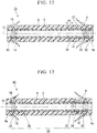
- a stent 31 of this embodiment includes a coil 33 comprising, a marker coil part 32 formed by winding a wire 2 at a predetermined position on an axis C1 of the coil 3 around that axis C1 so that it is substantially close coiling, and normal-wound coil parts 34 and 35 which are wound at the same pitch P1 as the wires 2 of the coil 3 of the first embodiment, instead of the coil 3 of the stent 1 of the first embodiment.
- 'close coiling' denotes that the wire is wound at a pitch with a fixed value that is greater than one times and seven times or less the outer diameter of the wire.
- the gap between adjacent wires 2 is 0.01 mm to 0.08 mm
- the pitch P2 of the wires 2 is 0.12 mm to 0.19 mm.
- the pitch P2 of the wires 2 is approximately 1.1 times to 1.7 times the outer diameter of the wires 2. To simplify the explanation, this gap is not shown in the drawings.
- the outer layer 4 and the inner layer 5 can be connected to each other in the section of the gap between adjacent wires 2, making them less likely to separate from each other.
- the size of the marker coil part 32 deviates from that described above, there will be no difference at radiopaque level between the coil pitch of the sparse part (i.e. the normal-wound coil) and the coil pitch of the close part (i.e. the marker coil part).
- the length of the marker coil part 32 in the axis C1 direction is preferably 9 mm or less. This is in order to smoothly pass through the forceps stand of the endoscope opening. In a case where the freedom of the coil is fixed within a given range, if the length of the marker coil part 32 in the axis C1 direction is 9 mm or more, there is a possibility that it will be difficult for it to pass forceps stand when the forceps stand is stood.
- the distal end of the marker coil part 32 is disposed such that it is at the same position as the proximal end of the notched part 12 in the axis C1 direction.
- Sections of the coil 33 other than the marker coil part 32 are configured with the normal-wound coil parts 34 and 35, which are wound at the same pitch P1 (about 0.41 mm) as the wires 2 of the coil 3 of the first embodiment.
- the pitch P1 of the wires 2 in the normal-wound coil parts 34 and 35 is preferably two times or more and twenty times or less the pitch P2 of the wires 2 of the marker coil part 32.
- the pitch P1 1 is less than two times the pitch P2, it becomes difficult to distinguish the marker coil part 32 from the normal-wound coil parts 34 and 35 under radioscopy. If the pitch P1 is more than twenty times the pitch P2, it becomes impossible to maintain the size of the lumen when the stent 31 is bent. Furthermore, the resin cannot enter into the gaps between the wires 2 wound at pitch P2, and that section consequently bulges.
- the normal-wound coil part 34 is connected to the distal end of the marker coil part 32, and the normal-wound coil part 35 is connected to the proximal end of the marker coil part 32.
- the marker coil part 32, the normal-wound coil part 34, and the normal-wound coil part 35 constitute the coil 33.
- the radiopacity (X-ray shielding level) of the marker coil part 32 and the radiopacity of the normal-wound coil parts 34 and 35 are sufficiently different to be viewable. It is therefore possible to identify the interface between the marker coil part 32 and the normal-wound coil part 34, and the interface between the marker coil part 32 and the normal-wound coil part 35.
- the user insert the stent 31 into the bile duct H2 while identifying the shape of the bile duct H2 and the position of the marker coil part 32 of the coil 33.
- the stent 31 is stopped inserting when the marker coil part 32 has passed beyond the stricture H3, the flaps 8-11 widen and engage with the stricture H3.
- flaps are formed on the distal-end part and on the proximal-end part so that they open in a natural state.
- the flaps formed on the distal-end part presses against the stricture and closes.
- the closed flaps open and engage with the bile duct, thereby suppressing the remove of the stent toward the duodenal papilla side.
- the thickness can be suppressed to enable the stent 31 to bend easily, and, in addition, the stent 31 is always collapse-resistant, even if it is subjected to a bending load due to flexion of the bile duct, removing change, or the like, as in the stent 1 of the first embodiment.
- the pitch at which the wires 2 are wound is different in the marker coil part 32 than in the normal-wound coil parts 34 and 35. Therefore, when X-rays of a fixed intensity are irradiated to the coil 33, a difference is generated between the radiopacity of the marker coil part 32 and the radiopacity of the normal-wound coil parts 34 and 35. Under radioscopy, the positions of the distal ends (free ends) of the flaps 8 -11 of the stent 31 can be viewed from this difference in intensity.
- the strength of the flap 8 can be increased. Also, a cause of physicality deterioration of the flap 8 can thereby be reduced.
- the marker coil part 32 is provided in an intermediate part of the axis C1 direction of the stent 31, the whole stent 31 can be confirmed more clearly. When placing a plurality of stents, this is useful in placing the second and subsequent stents.
- the flaps 8-11 are pressingly engaged with the inner walls of the stricture H3, and their free ends move to the outer peripheral face side of the outer layer 4.
- the user can confirm the shape of the bile duct H2 and the position of the marker coil part 32 of the stent 31 under radioscopy.
- the X-ray marker positioned near the flaps 8-11 is the marker coil part 32, it can bend flexibly in accordance with the bending of local parts.
- the user advances the marker coil part 32 of the stent 31 past the stricture H3 of the bile duct H2 and into the bile duct 2, thereby the free ends of the flaps 8-11 is freed from the pressure that the stricture H3 is applying to the free ends of the flaps 8-11. Since the free end sides of the flaps 8-11 now open to the outer side in the radius direction of the outer layer 4 due to their own elasticity, the flaps 8-11 of the stent 31 engage with the deep side of the stricture H3 of the bile duct H2.
- the user advances the marker coil part 32, which can be identified under radioscopy, past the stricture H3 of the bile duct H2 and into the bile duct H2, thereby making the flaps 8-11 engage reliably with the deep side of the stricture H3 of the bile duct H2.
- the marker coil part 32 can be disposed such that its proximal end is at the same position as the distal end of the notched part 12 in the direction of the axis C1.
- a marker coil part 42 and a marker coil part 43 formed from wires 2 wound around the axis C1 with close coiling in the same manner as the marker coil part 32, at both the distal end and the proximal end of the coil 33.
- the stent 41 When the stent 41 is configured in this way, the positions of the distal end and the proximal end of the coil 33 can be reliably viewed under radioscopy by the marker coil parts 42 and 43.
- the marker coil part 43 enables the force acting on the proximal-end part 4b side at the time of insertion to be transmitted efficiently to the distal-end part 4a side of the stent 41.
- the marker coil part 43 is strong against compression in the axis C1 direction, and there is a small distance between the wires 2 in the close part (marker coil part) where the wires are wound more closely than in the spare part (normal-wound coil part) where they are wound comparatively sparsely, making it difficult for the resin to sufficiently fill the gaps between the wires 2.
- the close part has a slightly larger outer diameter than the sparse part.
- the significance of this is that the area of the tube cross-section when transmitting the force from the proximal-end part 4b side to the distal-end part 4a side is large. Therefore, if the marker coil part 43 where the wires are comparatively close coiling is provided in the proximal-end part 4b, which is the side that directly receives the force, it will be easy to insert the stent 41.
- a stent 51 of this embodiment includes a coil 53 instead of the coil 33 of the stent 41 of the modification of the second embodiment.
- the coil 53 includes a normal-wound coil part 35, marker coil parts 42 and 43 provided at respective ends of the coil 53, a coarse-wound coil part 54 provided between the normal-wound coil part 35 and the marker coil part 42, and a coarse-wound coil part 55 provided between the normal-wound coil part 35 and the marker coil part 43.
- the pitch P1 of the wires 2 in the normal-wound coil part 35 is two times or more and twenty times or less the pitch P2 of the wires 2 in the marker coil parts 42 and 43, while the pitch P3 of the wires 2 in the coarse-wound coil parts 54 and 55 is 1.1 times or more and 5 times or less the pitch P1 of the wires 2 in the normal-wound coil part 35.
- the pitch of the wires 2 in the coarse-wound coil parts 54 and 55 is 1.1 times or more the pitch of the wires 2 in the normal-wound coil part 35, the interface between the coarse-wound coil part 54 and the normal-wound coil part 35, and the interface between the coarse-wound coil part 55 and the normal-wound coil part 35, can be viewed under radioscopy.
- the pitch of the wires 2 in the coarse-wound coil part 54 is two times or more the pitch of the wires 2 in the marker coil part 42
- the pitch of the wires 2 in the coarse-wound coil part 55 is two times or more the pitch of the wires 2 in the marker coil part 43
- the interface between the coarse-wound coil part 54 and the marker coil part 42, and the interface between the coarse-wound coil part 55 and the marker coil part 43 can also be viewed under radioscopy.
- the coarse-wound coil part 54 and the coarse-wound coil part 55 are provided in ranges with the axis C1 direction that nearly correspond to the flaps 8-11 and the flaps 16-19 respectively.
- the stent 51 of this embodiment with this configuration, as in the stents of each of the embodiments, it is possible to suppress the thickness and maintain ease of bending, while making the stent collapse-resistant.
- each of the flaps 8-11 and the flaps 16-19 can be identified by viewing the interfaces between the adjacent coils under radioscopy.
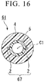
- a stent 61 of this embodiment includes a marker coil (coil) 64, a normal-wound coil (coil) 65, and a marker coil (coil) 66 at different positions on the axis C1, instead of the coil 53 of the stent 51 of the third embodiment.
- the marker coils 64 and 66 are formed by winding the wires 2 around the axis C1 so that they are substantially close-wound at the pitch P2 in the same manner as the marker coil part 32 described above.
- the normal-wound coil 65 is formed by winding the wires 2 around the axis C1 so that it is normal-wound at the pitch P1 in the same manner as the normal-wound coil part 35 described above.
- the normal-wound coil 65 and the marker coil 64 are connected to each other by a connection part 67, and the normal-wound coil 65 and the marker coil 66 are connected to each other by a connection part 68.
- connection part 67 is formed from a group of wires 2 that are parallel to the axis C1.
- the wires 2 are disposed so that they are in line symmetry with the axis C1, with one end of each of the wires 2 connected to the marker coil 64, and the other end connected to the normal-wound coil 65.
- Any type of publicly known method can be used to connect the wires 2 to the marker coil 64 and to the normal-wound coil 65, such as soldering, spot welding, connection using a T-shaped joint member, etc.
- connection part 67 The number and positions of wires 2 used for the connection part 67 can be set as appropriate.
- connection part 68 is formed from one group of wires 2, with one end of each of the wires 2 connected to the marker coil 66, and the other end connected to the normal-wound coil 65.
- the stent 61 of this embodiment with the above configuration, it is possible to suppress the thickness and maintain ease of bending, while making the stent collapse-resistant at all times, even if a bending load is applied to it due to flexion of the bile duct, traveling change, and such like.
- connection parts 67 and 68 are disposed so that they extend along the axis C1, a force acting in the axis C1 direction at the distal-end part 4a can be efficiently transmitted to the proximal-end part 4b, and a force acting in the axis C1 direction at the proximal-end part 4b can be efficiently transmitted to the distal-end part 4a.
- the force that the proximal-end part 4b of the stent 61 receives from the stent pusher is transmitted to the distal-end part 4a, enabling the stent 61 to be more easily inserted into the stricture H3 of the bile duct H2.
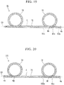
- a stent 71 of this embodiment has no flaps, and includes bending parts 72 and 73, which are formed in a so-called pigtail shape where they are rotated once so as to form a loop face parallel to an axis C2, at the distal-end part 4a and the proximal-end part 4b.
- a coil 75 described later is provided inside the outer layer 4, and the inner layer 5 described above (not shown) is provided inside the coil 75.
- a marker coil part 75a and a marker coil part 75b are respectively formed by winding wires 2 around the axis C2 at the same pitch P2 as the marker coil part 32 so that they are substantially close-coiling on the distal-end part 4a side from the interface M1 between the bending part 72 and the main part 74, and on the proximal-end part 4b side from the interface M2 between the bending part 73 and the main part 74.
- a normal-wound coil part 75c is formed by winding a wire 2 around the axis C2 at the same pitch P1 as the normal-wound coil part 35 described above.
- the positions of the interfaces M1 and M2, and the positions of the distal-end part 4a and the proximal-end part 4b can be identified under radioscopy. Furthermore, due to colour phase shading arising when the coil pitches are different, the interfaces can also be identified from their external appearances.
- a normal-wound coil part 82a and a normal-wound coil part 82b can be formed by winding the wire 2 around the axis C2 at the same pitch P1 as the normal-wound coil part 35; instead of the normal-wound coil part 75c, a marker coil part 82c can be formed by winding the wire 2 around the axis C2 at the same pitch P2 as the marker coil part 32, respectively.
- marker coil parts 92a and 92b by winding wires 2 around the axis C2 at the same pitch P2 as the marker coil part 32 so that they are substantially close-wound, can be provided only at a predetermined distance from the interface M1 and a predetermined distance from the distal-end part 4a respectively, and a normal-wound coil part 92c by winding the wire 2 around the axis C2 at the same pitch P1 as the normal-wound coil part 35 described above, can be provided between the marker coil parts 92a and 92b.
- the proximal-end part 4b side of the stent 91 can be configured in the same manner as the distal-end part 4a side.
- a coarse-wound coil part 102a can be provided by winding the wire 2 around the axis C2 at the same pitch as the coarse-wound coil part 54 described above.
- the proximal-end part 4b side of the stent 101 can be configured in the same manner as the distal-end part 4a side.
- a metal wire that is circular in cross-section is used as the wire 2.
- a wire that is square in cross-section can be spirally wound to form a flat coil.
- a stranded wire can also be used as the wire.
- the coil 3 is configured from a single winding wire 2, a plurality of wires can be aligned in the radial direction and spirally wound to form a so-called multiple wound wire.
- the marker coil part is formed by winding the wire 2 so that it is substantially close coiling.
- the wire 2 can be close coiling, with no gap provided between adjacent wires 2 of the marker coil part.
- the pitch of winding the wire 2 is changed to view the positions of connection sections of adjacent coils, the pitch can be kept fixed and the diameter of the wire changed instead.
- the medical stent of the present invention it is possible to maintain the property in which it is easy to bend and resilient force is weak, and to prevent the lumen from collapsing when bending bent. According to the medical stent of the present invention, it is possible to improve the imaging ability without decaying the flexibility and resilient force of the stent.
Landscapes
- Health & Medical Sciences (AREA)
- Engineering & Computer Science (AREA)
- Biomedical Technology (AREA)
- Animal Behavior & Ethology (AREA)
- Veterinary Medicine (AREA)
- Public Health (AREA)
- Heart & Thoracic Surgery (AREA)
- General Health & Medical Sciences (AREA)
- Life Sciences & Earth Sciences (AREA)
- Transplantation (AREA)
- Vascular Medicine (AREA)
- Oral & Maxillofacial Surgery (AREA)
- Cardiology (AREA)
- Urology & Nephrology (AREA)
- Ophthalmology & Optometry (AREA)
- Otolaryngology (AREA)
- Anesthesiology (AREA)
- Hematology (AREA)
- Gastroenterology & Hepatology (AREA)
- Pulmonology (AREA)
- Media Introduction/Drainage Providing Device (AREA)
Claims (5)
bei dem der Markierungsspiralteil (75a, 75b, 82c, 92a) aus einem röntgenstrahlenundurchlässigen Material gebildet ist.
bei dem der Markierungsspiralteil (75a, 75b, 82c, 92a) von der Schnittstelle zu einem distalen Endteil oder einem proximalen Endteil des Stents ausgebildet ist.
bei dem der Markierungsspiralteil (75a, 75b, 82c, 92a) in dem Hauptteil vorgesehen ist,
wobei eines der Enden des Markierungsspiralteils (75a, 75b, 82c, 92a) zwischen der Schnittstelle (M1, M2) und dem anderen Ende des Hauptteils (74) angeordnet ist
bei dem der Markierungsspiralteil (75a, 75b, 82c, 92a) mit einer Steigung mit einem festen Wert gewickelt ist, der größer als einmal der Außendurchmesser des Drahtes und siebenmal oder weniger als der Außendurchmessers des Drahtes ist.
Applications Claiming Priority (2)
| Application Number | Priority Date | Filing Date | Title |
|---|---|---|---|
| JP2010073817 | 2010-03-26 | ||
| EP10848473.4A EP2489334B1 (de) | 2010-03-26 | 2010-11-12 | Medizinischer stent |
Related Parent Applications (2)
| Application Number | Title | Priority Date | Filing Date |
|---|---|---|---|
| EP10848473.4A Division-Into EP2489334B1 (de) | 2010-03-26 | 2010-11-12 | Medizinischer stent |
| EP10848473.4A Division EP2489334B1 (de) | 2010-03-26 | 2010-11-12 | Medizinischer stent |
Publications (2)
| Publication Number | Publication Date |
|---|---|
| EP2803339A1 EP2803339A1 (de) | 2014-11-19 |
| EP2803339B1 true EP2803339B1 (de) | 2016-12-28 |
Family
ID=44672665
Family Applications (2)
| Application Number | Title | Priority Date | Filing Date |
|---|---|---|---|
| EP10848473.4A Active EP2489334B1 (de) | 2010-03-26 | 2010-11-12 | Medizinischer stent |
| EP14172081.3A Not-in-force EP2803339B1 (de) | 2010-03-26 | 2010-11-12 | Medizinischer Stent |
Family Applications Before (1)
| Application Number | Title | Priority Date | Filing Date |
|---|---|---|---|
| EP10848473.4A Active EP2489334B1 (de) | 2010-03-26 | 2010-11-12 | Medizinischer stent |
Country Status (5)
| Country | Link |
|---|---|
| US (2) | US8632606B2 (de) |
| EP (2) | EP2489334B1 (de) |
| JP (1) | JP4981994B2 (de) |
| CN (1) | CN102655824B (de) |
| WO (1) | WO2011118081A1 (de) |
Families Citing this family (33)
| Publication number | Priority date | Publication date | Assignee | Title |
|---|---|---|---|---|
| US9387312B2 (en) | 2008-09-15 | 2016-07-12 | Brightwater Medical, Inc. | Convertible nephroureteral catheter |
| US20130158673A1 (en) | 2011-12-15 | 2013-06-20 | Cook Medical Technologies Llc | Anti-Leakage Prosthesis |
| KR101382524B1 (ko) * | 2012-02-27 | 2014-04-07 | 국립암센터 | 돌출형 부분이중구조 스텐트 |
| WO2014014748A1 (en) * | 2012-07-20 | 2014-01-23 | Cook Medical Technologies Llc | Anti -migration biliary stent |
| EP2749310A1 (de) | 2012-12-28 | 2014-07-02 | Cook Medical Technologies LLC | Endoluminale Harnröhrenvorrichtung |
| EP2777604B1 (de) * | 2013-01-23 | 2018-10-03 | Cook Medical Technologies LLC | Stent mit Positionierungsarmen |
| CA2902775C (en) * | 2013-02-28 | 2017-11-28 | Boston Scientific Scimed, Inc. | Medical devices for use along the biliary and/or pancreatic tract |
| EP2965723B1 (de) | 2013-03-07 | 2024-07-10 | Olympus Corporation | Medizinischer stent |
| WO2014164308A1 (en) * | 2013-03-13 | 2014-10-09 | Boston Scientific Scimed, Inc. | Pancreatic stent drainage system |
| WO2014143730A1 (en) * | 2013-03-15 | 2014-09-18 | Boston Scientific Scimed, Inc. | Anti-migratory stent coating |
| JP6037946B2 (ja) * | 2013-06-10 | 2016-12-07 | オリンパス株式会社 | ステント留置装置 |
| JP5408682B1 (ja) * | 2013-06-28 | 2014-02-05 | ガデリウス・メディカル株式会社 | ステントキット |
| CA2956401C (en) | 2014-08-12 | 2022-10-25 | Brightwater Medical, Inc. | Systems and methods for coupling and decoupling a catheter |
| CN104188741A (zh) * | 2014-08-29 | 2014-12-10 | 东莞颠覆产品设计有限公司 | 一种植入体内的可降解接驳器 |
| KR102097542B1 (ko) * | 2014-12-19 | 2020-04-06 | 보스톤 싸이엔티픽 싸이메드 인코포레이티드 | 이동 방지 특성을 갖는 스텐트 |
| CN105769399A (zh) * | 2014-12-23 | 2016-07-20 | 刘凯 | 易取出式胰管支架 |
| WO2018012387A1 (ja) * | 2016-07-12 | 2018-01-18 | 株式会社パイオラックスメディカルデバイス | カバードステント |
| EP3725214A1 (de) * | 2016-11-29 | 2020-10-21 | Foundry Innovation & Research 1, Ltd. | Gefässimplantate mit drahtlosem resonanzkreis und variabler induktivität zur überwachung des gefässsystems |
| CN108236751B (zh) * | 2016-12-26 | 2025-03-11 | 上海英诺伟医疗器械股份有限公司 | 一种双层引流管 |
| US20180235790A1 (en) * | 2017-02-21 | 2018-08-23 | Brightwater Medical, Inc. | Systems and methods for coupling and decoupling a catheter |
| CN110769786B (zh) * | 2017-06-13 | 2022-12-09 | 株式会社钟化 | 生物体内留置管 |
| KR102149135B1 (ko) * | 2018-01-17 | 2020-08-31 | 서울대학교병원 | 돼지꼬리 구조를 갖는 이종 장기 간의 연결술용 스텐트 |
| CN113056243B (zh) * | 2018-11-22 | 2024-06-04 | 奥林巴斯株式会社 | 医疗用支架和支架输送装置 |
| EP3741331A1 (de) * | 2019-05-24 | 2020-11-25 | Seoul National University Hospital | Stent zur verbindung von ungleichen organen mit anschlusslitzenstruktur |
| JP7273428B2 (ja) * | 2019-07-10 | 2023-05-15 | 京都府公立大学法人 | 医療用イメージガイダンスマーカー |
| US12226327B2 (en) | 2020-04-15 | 2025-02-18 | Merit Medical Systems, Inc. | Systems and methods for coupling and decoupling a catheter |
| US12491097B2 (en) | 2020-06-05 | 2025-12-09 | Merit Medical Systems, Inc. | Systems and methods for coupling and decoupling a catheter |
| US12168102B2 (en) | 2020-07-07 | 2024-12-17 | Covidien Lp | Catheter including surface-treated structural support member |
| US11992625B2 (en) * | 2020-07-07 | 2024-05-28 | Covidien Lp | Catheter including variable density structural support member |
| EP3991945A1 (de) | 2020-10-30 | 2022-05-04 | Fundació Eurecat | 3d-druckvorrichtung und 3d-druckverfahren |
| US20220287818A1 (en) * | 2021-03-15 | 2022-09-15 | The Corporation Of Mercer University | Stents and methods of making and using the same |
| CN113633433A (zh) * | 2021-10-15 | 2021-11-12 | 微创神通医疗科技(上海)有限公司 | 血管植入物 |
| US12453844B2 (en) | 2023-09-22 | 2025-10-28 | JMT Medical, Inc. | Devices and methods for bile duct surgery |
Family Cites Families (20)
| Publication number | Priority date | Publication date | Assignee | Title |
|---|---|---|---|---|
| JP3619527B2 (ja) | 1991-10-16 | 2005-02-09 | オリンパス株式会社 | 生体内留置チューブ |
| US5282860A (en) * | 1991-10-16 | 1994-02-01 | Olympus Optical Co., Ltd. | Stent tube for medical use |
| US5514176A (en) * | 1995-01-20 | 1996-05-07 | Vance Products Inc. | Pull apart coil stent |
| ES2151082T3 (es) | 1995-03-10 | 2000-12-16 | Impra Inc | Soporte encapsulado endoluminal y procedimientos para su fabricacion y su colocacion endoluminal. |
| US6264684B1 (en) * | 1995-03-10 | 2001-07-24 | Impra, Inc., A Subsidiary Of C.R. Bard, Inc. | Helically supported graft |
| EP1275352A3 (de) * | 1996-09-20 | 2003-06-11 | Converge Medical, Inc. | Radial ausweitbare Prothesen sowie Systeme zu ihrer Entfaltung |
| US6093199A (en) * | 1998-08-05 | 2000-07-25 | Endovascular Technologies, Inc. | Intra-luminal device for treatment of body cavities and lumens and method of use |
| US6312457B1 (en) * | 1999-04-01 | 2001-11-06 | Boston Scientific Corporation | Intraluminal lining |
| EP1192970B1 (de) * | 1999-05-11 | 2011-07-20 | Kaneka Corporation | Ballonkatheter |
| US7169187B2 (en) | 1999-12-22 | 2007-01-30 | Ethicon, Inc. | Biodegradable stent |
| JP2002355316A (ja) * | 2001-03-30 | 2002-12-10 | Terumo Corp | ステントカバーおよびステント |
| US20030040803A1 (en) | 2001-08-23 | 2003-02-27 | Rioux Robert F. | Maintaining an open passageway through a body lumen |
| JP2004147700A (ja) | 2002-10-28 | 2004-05-27 | Sumitomo Bakelite Co Ltd | カテーテル |
| US20040087886A1 (en) * | 2002-10-30 | 2004-05-06 | Scimed Life Systems, Inc. | Linearly expandable ureteral stent |
| WO2004103207A2 (en) * | 2003-05-15 | 2004-12-02 | Applied Medical Resources Corporation | Echogenic stent |
| JP4901087B2 (ja) | 2004-09-24 | 2012-03-21 | オリンパス株式会社 | ステント導入部材、ステントデリバリーカテーテル、及び内視鏡処置システム |
| US20060167538A1 (en) * | 2004-12-23 | 2006-07-27 | Rucker Brian K | Inflatable biliary stent |
| DE202005001416U1 (de) * | 2005-01-28 | 2005-03-31 | Urovision Ges Fuer Medizinisch | Stent |
| US7789915B2 (en) * | 2005-08-31 | 2010-09-07 | Vance Products Incorporated | Stent for implantation |
| US20080051911A1 (en) * | 2006-08-23 | 2008-02-28 | Wilson-Cook Medical Inc. | Stent with antimicrobial drainage lumen surface |
-
2010
- 2010-11-12 CN CN201080056531.2A patent/CN102655824B/zh active Active
- 2010-11-12 EP EP10848473.4A patent/EP2489334B1/de active Active
- 2010-11-12 EP EP14172081.3A patent/EP2803339B1/de not_active Not-in-force
- 2010-11-12 WO PCT/JP2010/070197 patent/WO2011118081A1/ja not_active Ceased
- 2010-11-12 JP JP2011536679A patent/JP4981994B2/ja active Active
-
2011
- 2011-09-26 US US13/245,157 patent/US8632606B2/en active Active
-
2013
- 2013-12-23 US US14/138,772 patent/US9192493B2/en active Active
Also Published As
| Publication number | Publication date |
|---|---|
| US20140114431A1 (en) | 2014-04-24 |
| EP2489334A4 (de) | 2012-08-22 |
| US8632606B2 (en) | 2014-01-21 |
| EP2489334B1 (de) | 2014-07-16 |
| EP2803339A1 (de) | 2014-11-19 |
| CN102655824A (zh) | 2012-09-05 |
| JP4981994B2 (ja) | 2012-07-25 |
| US20120095545A1 (en) | 2012-04-19 |
| CN102655824B (zh) | 2014-10-29 |
| WO2011118081A1 (ja) | 2011-09-29 |
| JPWO2011118081A1 (ja) | 2013-07-04 |
| EP2489334A1 (de) | 2012-08-22 |
| US9192493B2 (en) | 2015-11-24 |
Similar Documents
| Publication | Publication Date | Title |
|---|---|---|
| EP2803339B1 (de) | Medizinischer Stent | |
| JP5284165B2 (ja) | 生体器官病変部改善用器具 | |
| CN114555168A (zh) | 导管 | |
| JP3662885B2 (ja) | 人造血管ステントおよびステント挿入装置 | |
| CN112438770A (zh) | 输送导丝和管腔植入系统 | |
| CN100469398C (zh) | 引导钢丝 | |
| WO2020014536A1 (en) | Implant delivery system and method of use | |
| WO2006111945A2 (en) | A retrieval catheter | |
| US10383719B2 (en) | Stent for medical use | |
| US20240058574A1 (en) | Medical catheter and preparation method therefor | |
| WO2010038634A1 (ja) | ステントデリバリーシステム | |
| RU2521351C2 (ru) | Маркер и стент | |
| JP2007507301A (ja) | 除去可能なステント | |
| CN210990521U (zh) | 输送导丝和管腔植入系统 | |
| EP2896426B1 (de) | Litzendraht und Führungsdraht damit | |
| EP3821857B1 (de) | Stent und verfahren zu dessen prüfung | |
| CN113647923A (zh) | 一种具有监测血压功能的医用导丝 | |
| JP2006075232A (ja) | 血管内異物除去用ワイヤおよび医療器具 | |
| CN105457142B (zh) | 导丝 | |
| EP3988156A1 (de) | Führungsdraht | |
| US20240180560A1 (en) | Embolic coil delivery systems and components with frangible release features | |
| WO2025211069A1 (ja) | 医療デバイス | |
| JP2004208704A (ja) | 医療用ガイドワイヤ | |
| US20230053337A1 (en) | Delivery guidewire and therapeutic treatment device | |
| WO2026082149A1 (zh) | 输送装置 |
Legal Events
| Date | Code | Title | Description |
|---|---|---|---|
| PUAI | Public reference made under article 153(3) epc to a published international application that has entered the european phase |
Free format text: ORIGINAL CODE: 0009012 |
|
| 17P | Request for examination filed |
Effective date: 20140612 |
|
| AC | Divisional application: reference to earlier application |
Ref document number: 2489334 Country of ref document: EP Kind code of ref document: P |
|
| AK | Designated contracting states |
Kind code of ref document: A1 Designated state(s): AL AT BE BG CH CY CZ DE DK EE ES FI FR GB GR HR HU IE IS IT LI LT LU LV MC MK MT NL NO PL PT RO RS SE SI SK SM TR |
|
| R17P | Request for examination filed (corrected) |
Effective date: 20150504 |
|
| RBV | Designated contracting states (corrected) |
Designated state(s): AL AT BE BG CH CY CZ DE DK EE ES FI FR GB GR HR HU IE IS IT LI LT LU LV MC MK MT NL NO PL PT RO RS SE SI SK SM TR |
|
| RAP1 | Party data changed (applicant data changed or rights of an application transferred) |
Owner name: OLYMPUS CORPORATION |
|
| 17Q | First examination report despatched |
Effective date: 20151007 |
|
| GRAP | Despatch of communication of intention to grant a patent |
Free format text: ORIGINAL CODE: EPIDOSNIGR1 |
|
| INTG | Intention to grant announced |
Effective date: 20160617 |
|
| RAP1 | Party data changed (applicant data changed or rights of an application transferred) |
Owner name: OLYMPUS CORPORATION |
|
| RAP1 | Party data changed (applicant data changed or rights of an application transferred) |
Owner name: OLYMPUS CORPORATION |
|
| GRAS | Grant fee paid |
Free format text: ORIGINAL CODE: EPIDOSNIGR3 |
|
| GRAA | (expected) grant |
Free format text: ORIGINAL CODE: 0009210 |
|
| STAA | Information on the status of an ep patent application or granted ep patent |
Free format text: STATUS: THE PATENT HAS BEEN GRANTED |
|
| AC | Divisional application: reference to earlier application |
Ref document number: 2489334 Country of ref document: EP Kind code of ref document: P |
|
| AK | Designated contracting states |
Kind code of ref document: B1 Designated state(s): AL AT BE BG CH CY CZ DE DK EE ES FI FR GB GR HR HU IE IS IT LI LT LU LV MC MK MT NL NO PL PT RO RS SE SI SK SM TR |
|
| REG | Reference to a national code |
Ref country code: GB Ref legal event code: FG4D |
|
| REG | Reference to a national code |
Ref country code: CH Ref legal event code: EP |
|
| REG | Reference to a national code |
Ref country code: AT Ref legal event code: REF Ref document number: 856665 Country of ref document: AT Kind code of ref document: T Effective date: 20170115 |
|
| REG | Reference to a national code |
Ref country code: IE Ref legal event code: FG4D |
|
| REG | Reference to a national code |
Ref country code: DE Ref legal event code: R096 Ref document number: 602010039259 Country of ref document: DE |
|
| PG25 | Lapsed in a contracting state [announced via postgrant information from national office to epo] |
Ref country code: LV Free format text: LAPSE BECAUSE OF FAILURE TO SUBMIT A TRANSLATION OF THE DESCRIPTION OR TO PAY THE FEE WITHIN THE PRESCRIBED TIME-LIMIT Effective date: 20161228 |
|
| REG | Reference to a national code |
Ref country code: LT Ref legal event code: MG4D |
|
| PG25 | Lapsed in a contracting state [announced via postgrant information from national office to epo] |
Ref country code: NO Free format text: LAPSE BECAUSE OF FAILURE TO SUBMIT A TRANSLATION OF THE DESCRIPTION OR TO PAY THE FEE WITHIN THE PRESCRIBED TIME-LIMIT Effective date: 20170328 Ref country code: LT Free format text: LAPSE BECAUSE OF FAILURE TO SUBMIT A TRANSLATION OF THE DESCRIPTION OR TO PAY THE FEE WITHIN THE PRESCRIBED TIME-LIMIT Effective date: 20161228 Ref country code: SE Free format text: LAPSE BECAUSE OF FAILURE TO SUBMIT A TRANSLATION OF THE DESCRIPTION OR TO PAY THE FEE WITHIN THE PRESCRIBED TIME-LIMIT Effective date: 20161228 Ref country code: GR Free format text: LAPSE BECAUSE OF FAILURE TO SUBMIT A TRANSLATION OF THE DESCRIPTION OR TO PAY THE FEE WITHIN THE PRESCRIBED TIME-LIMIT Effective date: 20170329 |
|
| REG | Reference to a national code |
Ref country code: NL Ref legal event code: MP Effective date: 20161228 |
|
| REG | Reference to a national code |
Ref country code: AT Ref legal event code: MK05 Ref document number: 856665 Country of ref document: AT Kind code of ref document: T Effective date: 20161228 |
|
| PG25 | Lapsed in a contracting state [announced via postgrant information from national office to epo] |
Ref country code: FI Free format text: LAPSE BECAUSE OF FAILURE TO SUBMIT A TRANSLATION OF THE DESCRIPTION OR TO PAY THE FEE WITHIN THE PRESCRIBED TIME-LIMIT Effective date: 20161228 Ref country code: HR Free format text: LAPSE BECAUSE OF FAILURE TO SUBMIT A TRANSLATION OF THE DESCRIPTION OR TO PAY THE FEE WITHIN THE PRESCRIBED TIME-LIMIT Effective date: 20161228 Ref country code: RS Free format text: LAPSE BECAUSE OF FAILURE TO SUBMIT A TRANSLATION OF THE DESCRIPTION OR TO PAY THE FEE WITHIN THE PRESCRIBED TIME-LIMIT Effective date: 20161228 |
|
| PG25 | Lapsed in a contracting state [announced via postgrant information from national office to epo] |
Ref country code: NL Free format text: LAPSE BECAUSE OF FAILURE TO SUBMIT A TRANSLATION OF THE DESCRIPTION OR TO PAY THE FEE WITHIN THE PRESCRIBED TIME-LIMIT Effective date: 20161228 |
|
| PG25 | Lapsed in a contracting state [announced via postgrant information from national office to epo] |
Ref country code: EE Free format text: LAPSE BECAUSE OF FAILURE TO SUBMIT A TRANSLATION OF THE DESCRIPTION OR TO PAY THE FEE WITHIN THE PRESCRIBED TIME-LIMIT Effective date: 20161228 Ref country code: IS Free format text: LAPSE BECAUSE OF FAILURE TO SUBMIT A TRANSLATION OF THE DESCRIPTION OR TO PAY THE FEE WITHIN THE PRESCRIBED TIME-LIMIT Effective date: 20170428 Ref country code: RO Free format text: LAPSE BECAUSE OF FAILURE TO SUBMIT A TRANSLATION OF THE DESCRIPTION OR TO PAY THE FEE WITHIN THE PRESCRIBED TIME-LIMIT Effective date: 20161228 Ref country code: CZ Free format text: LAPSE BECAUSE OF FAILURE TO SUBMIT A TRANSLATION OF THE DESCRIPTION OR TO PAY THE FEE WITHIN THE PRESCRIBED TIME-LIMIT Effective date: 20161228 Ref country code: SK Free format text: LAPSE BECAUSE OF FAILURE TO SUBMIT A TRANSLATION OF THE DESCRIPTION OR TO PAY THE FEE WITHIN THE PRESCRIBED TIME-LIMIT Effective date: 20161228 |
|
| PG25 | Lapsed in a contracting state [announced via postgrant information from national office to epo] |
Ref country code: PT Free format text: LAPSE BECAUSE OF FAILURE TO SUBMIT A TRANSLATION OF THE DESCRIPTION OR TO PAY THE FEE WITHIN THE PRESCRIBED TIME-LIMIT Effective date: 20170428 Ref country code: BG Free format text: LAPSE BECAUSE OF FAILURE TO SUBMIT A TRANSLATION OF THE DESCRIPTION OR TO PAY THE FEE WITHIN THE PRESCRIBED TIME-LIMIT Effective date: 20170328 Ref country code: AT Free format text: LAPSE BECAUSE OF FAILURE TO SUBMIT A TRANSLATION OF THE DESCRIPTION OR TO PAY THE FEE WITHIN THE PRESCRIBED TIME-LIMIT Effective date: 20161228 Ref country code: SM Free format text: LAPSE BECAUSE OF FAILURE TO SUBMIT A TRANSLATION OF THE DESCRIPTION OR TO PAY THE FEE WITHIN THE PRESCRIBED TIME-LIMIT Effective date: 20161228 Ref country code: IT Free format text: LAPSE BECAUSE OF FAILURE TO SUBMIT A TRANSLATION OF THE DESCRIPTION OR TO PAY THE FEE WITHIN THE PRESCRIBED TIME-LIMIT Effective date: 20161228 Ref country code: BE Free format text: LAPSE BECAUSE OF FAILURE TO SUBMIT A TRANSLATION OF THE DESCRIPTION OR TO PAY THE FEE WITHIN THE PRESCRIBED TIME-LIMIT Effective date: 20161228 Ref country code: PL Free format text: LAPSE BECAUSE OF FAILURE TO SUBMIT A TRANSLATION OF THE DESCRIPTION OR TO PAY THE FEE WITHIN THE PRESCRIBED TIME-LIMIT Effective date: 20161228 Ref country code: ES Free format text: LAPSE BECAUSE OF FAILURE TO SUBMIT A TRANSLATION OF THE DESCRIPTION OR TO PAY THE FEE WITHIN THE PRESCRIBED TIME-LIMIT Effective date: 20161228 |
|
| REG | Reference to a national code |
Ref country code: DE Ref legal event code: R097 Ref document number: 602010039259 Country of ref document: DE |
|
| PLBE | No opposition filed within time limit |
Free format text: ORIGINAL CODE: 0009261 |
|
| STAA | Information on the status of an ep patent application or granted ep patent |
Free format text: STATUS: NO OPPOSITION FILED WITHIN TIME LIMIT |
|
| PG25 | Lapsed in a contracting state [announced via postgrant information from national office to epo] |
Ref country code: DK Free format text: LAPSE BECAUSE OF FAILURE TO SUBMIT A TRANSLATION OF THE DESCRIPTION OR TO PAY THE FEE WITHIN THE PRESCRIBED TIME-LIMIT Effective date: 20161228 |
|
| 26N | No opposition filed |
Effective date: 20170929 |
|
| PG25 | Lapsed in a contracting state [announced via postgrant information from national office to epo] |
Ref country code: SI Free format text: LAPSE BECAUSE OF FAILURE TO SUBMIT A TRANSLATION OF THE DESCRIPTION OR TO PAY THE FEE WITHIN THE PRESCRIBED TIME-LIMIT Effective date: 20161228 |
|
| PG25 | Lapsed in a contracting state [announced via postgrant information from national office to epo] |
Ref country code: MC Free format text: LAPSE BECAUSE OF FAILURE TO SUBMIT A TRANSLATION OF THE DESCRIPTION OR TO PAY THE FEE WITHIN THE PRESCRIBED TIME-LIMIT Effective date: 20161228 |
|
| GBPC | Gb: european patent ceased through non-payment of renewal fee |
Effective date: 20171112 |
|
| PG25 | Lapsed in a contracting state [announced via postgrant information from national office to epo] |
Ref country code: LI Free format text: LAPSE BECAUSE OF NON-PAYMENT OF DUE FEES Effective date: 20171130 Ref country code: CH Free format text: LAPSE BECAUSE OF NON-PAYMENT OF DUE FEES Effective date: 20171130 |
|
| PG25 | Lapsed in a contracting state [announced via postgrant information from national office to epo] |
Ref country code: LU Free format text: LAPSE BECAUSE OF NON-PAYMENT OF DUE FEES Effective date: 20171112 |
|
| REG | Reference to a national code |
Ref country code: FR Ref legal event code: ST Effective date: 20180731 |
|
| REG | Reference to a national code |
Ref country code: IE Ref legal event code: MM4A |
|
| PG25 | Lapsed in a contracting state [announced via postgrant information from national office to epo] |
Ref country code: MT Free format text: LAPSE BECAUSE OF NON-PAYMENT OF DUE FEES Effective date: 20171112 |
|
| PG25 | Lapsed in a contracting state [announced via postgrant information from national office to epo] |
Ref country code: FR Free format text: LAPSE BECAUSE OF NON-PAYMENT OF DUE FEES Effective date: 20171130 Ref country code: IE Free format text: LAPSE BECAUSE OF NON-PAYMENT OF DUE FEES Effective date: 20171112 |
|
| PG25 | Lapsed in a contracting state [announced via postgrant information from national office to epo] |
Ref country code: GB Free format text: LAPSE BECAUSE OF NON-PAYMENT OF DUE FEES Effective date: 20171112 |
|
| PGFP | Annual fee paid to national office [announced via postgrant information from national office to epo] |
Ref country code: DE Payment date: 20181120 Year of fee payment: 9 |
|
| PG25 | Lapsed in a contracting state [announced via postgrant information from national office to epo] |
Ref country code: HU Free format text: LAPSE BECAUSE OF FAILURE TO SUBMIT A TRANSLATION OF THE DESCRIPTION OR TO PAY THE FEE WITHIN THE PRESCRIBED TIME-LIMIT; INVALID AB INITIO Effective date: 20101112 |
|
| PG25 | Lapsed in a contracting state [announced via postgrant information from national office to epo] |
Ref country code: CY Free format text: LAPSE BECAUSE OF FAILURE TO SUBMIT A TRANSLATION OF THE DESCRIPTION OR TO PAY THE FEE WITHIN THE PRESCRIBED TIME-LIMIT Effective date: 20161228 |
|
| PG25 | Lapsed in a contracting state [announced via postgrant information from national office to epo] |
Ref country code: MK Free format text: LAPSE BECAUSE OF FAILURE TO SUBMIT A TRANSLATION OF THE DESCRIPTION OR TO PAY THE FEE WITHIN THE PRESCRIBED TIME-LIMIT Effective date: 20161228 |
|
| PG25 | Lapsed in a contracting state [announced via postgrant information from national office to epo] |
Ref country code: TR Free format text: LAPSE BECAUSE OF FAILURE TO SUBMIT A TRANSLATION OF THE DESCRIPTION OR TO PAY THE FEE WITHIN THE PRESCRIBED TIME-LIMIT Effective date: 20161228 |
|
| REG | Reference to a national code |
Ref country code: DE Ref legal event code: R119 Ref document number: 602010039259 Country of ref document: DE |
|
| PG25 | Lapsed in a contracting state [announced via postgrant information from national office to epo] |
Ref country code: AL Free format text: LAPSE BECAUSE OF FAILURE TO SUBMIT A TRANSLATION OF THE DESCRIPTION OR TO PAY THE FEE WITHIN THE PRESCRIBED TIME-LIMIT Effective date: 20161228 |
|
| PG25 | Lapsed in a contracting state [announced via postgrant information from national office to epo] |
Ref country code: DE Free format text: LAPSE BECAUSE OF NON-PAYMENT OF DUE FEES Effective date: 20200603 |