EP2803368A1 - Dispositif et procédé destinés à la stérilisation de récipients dotés de dispositif de blindage contre les rayons X - Google Patents
Dispositif et procédé destinés à la stérilisation de récipients dotés de dispositif de blindage contre les rayons X Download PDFInfo
- Publication number
- EP2803368A1 EP2803368A1 EP14001716.1A EP14001716A EP2803368A1 EP 2803368 A1 EP2803368 A1 EP 2803368A1 EP 14001716 A EP14001716 A EP 14001716A EP 2803368 A1 EP2803368 A1 EP 2803368A1
- Authority
- EP
- European Patent Office
- Prior art keywords
- containers
- radiation
- transport path
- wall
- sterilization
- Prior art date
- Legal status (The legal status is an assumption and is not a legal conclusion. Google has not performed a legal analysis and makes no representation as to the accuracy of the status listed.)
- Granted
Links
Images


Classifications
-
- A—HUMAN NECESSITIES
- A61—MEDICAL OR VETERINARY SCIENCE; HYGIENE
- A61L—METHODS OR APPARATUS FOR STERILISING MATERIALS OR OBJECTS IN GENERAL; DISINFECTION, STERILISATION OR DEODORISATION OF AIR; CHEMICAL ASPECTS OF BANDAGES, DRESSINGS, ABSORBENT PADS OR SURGICAL ARTICLES; MATERIALS FOR BANDAGES, DRESSINGS, ABSORBENT PADS OR SURGICAL ARTICLES
- A61L2/00—Disinfection or sterilisation of materials or objects, in general; Accessories therefor
- A61L2/02—Disinfection or sterilisation of materials or objects, in general; Accessories therefor using physical processes
- A61L2/08—Radiation
- A61L2/082—X-rays
-
- A—HUMAN NECESSITIES
- A61—MEDICAL OR VETERINARY SCIENCE; HYGIENE
- A61L—METHODS OR APPARATUS FOR STERILISING MATERIALS OR OBJECTS IN GENERAL; DISINFECTION, STERILISATION OR DEODORISATION OF AIR; CHEMICAL ASPECTS OF BANDAGES, DRESSINGS, ABSORBENT PADS OR SURGICAL ARTICLES; MATERIALS FOR BANDAGES, DRESSINGS, ABSORBENT PADS OR SURGICAL ARTICLES
- A61L2/00—Disinfection or sterilisation of materials or objects, in general; Accessories therefor
- A61L2/02—Disinfection or sterilisation of materials or objects, in general; Accessories therefor using physical processes
- A61L2/08—Radiation
- A61L2/087—Particle radiation, e.g. electron-beam, alpha or beta radiation
-
- B—PERFORMING OPERATIONS; TRANSPORTING
- B65—CONVEYING; PACKING; STORING; HANDLING THIN OR FILAMENTARY MATERIAL
- B65B—MACHINES, APPARATUS OR DEVICES FOR, OR METHODS OF, PACKAGING ARTICLES OR MATERIALS; UNPACKING
- B65B55/00—Preserving, protecting or purifying packages or package contents in association with packaging
- B65B55/02—Sterilising, e.g. of complete packages
- B65B55/04—Sterilising wrappers or receptacles prior to, or during, packaging
- B65B55/08—Sterilising wrappers or receptacles prior to, or during, packaging by irradiation
-
- A—HUMAN NECESSITIES
- A61—MEDICAL OR VETERINARY SCIENCE; HYGIENE
- A61L—METHODS OR APPARATUS FOR STERILISING MATERIALS OR OBJECTS IN GENERAL; DISINFECTION, STERILISATION OR DEODORISATION OF AIR; CHEMICAL ASPECTS OF BANDAGES, DRESSINGS, ABSORBENT PADS OR SURGICAL ARTICLES; MATERIALS FOR BANDAGES, DRESSINGS, ABSORBENT PADS OR SURGICAL ARTICLES
- A61L2103/00—Materials or objects being the target of disinfection or sterilisation
- A61L2103/23—Containers other than laboratory or medical, e.g. bottles or mail
-
- A—HUMAN NECESSITIES
- A61—MEDICAL OR VETERINARY SCIENCE; HYGIENE
- A61L—METHODS OR APPARATUS FOR STERILISING MATERIALS OR OBJECTS IN GENERAL; DISINFECTION, STERILISATION OR DEODORISATION OF AIR; CHEMICAL ASPECTS OF BANDAGES, DRESSINGS, ABSORBENT PADS OR SURGICAL ARTICLES; MATERIALS FOR BANDAGES, DRESSINGS, ABSORBENT PADS OR SURGICAL ARTICLES
- A61L2202/00—Aspects relating to methods or apparatus for disinfecting or sterilising materials or objects
- A61L2202/10—Apparatus features
- A61L2202/12—Apparatus for isolating biocidal substances from the environment
Definitions
- the present invention relates to an apparatus and a method for sterilizing containers.
- Various such methods are known from the prior art and are used, for example, to sterilize plastic containers and in particular plastic preforms before their further processing.
- Sterilization processes have long been known in which the plastic containers are exposed to a sterilizing agent, such as hydrogen peroxide or peracetic acid.
- a sterilizing agent such as hydrogen peroxide or peracetic acid.
- electromagnetic radiation such as electron beams, ultraviolet or X-rays.
- the use of such rays is on the one hand resource-saving, since no additional sterilizing agent must be used, but the disadvantage is that often dangerous radiation, such as ionizing radiation, in particular X-rays, arises.
- shielding devices are known from the prior art.
- shields of ionizing radiation such as X-rays
- sterilization systems for example, by rotating or moving Strahlentrennetti accomplished, which are arranged between the individual objects to be treated or by tunnel-like arrangement of mostly stationary separating elements, the dimensioning of the diameter with respect depends on the existing bow angle or on the gap width.
- the disadvantage of such mitbedorfder or co-rotating separating elements is that the ventilation technology at different speeds in different Way is influenced.
- radiation sealing of lock stars and directly on a radiation source of the treatment star is difficult.
- Such embodiments are also problematic in narrow divisions between the individual objects to be sterilized.
- the assembly is complicated and it can also come to a snagging of lost containers.
- the provision of a radiation tunnel leads to the fact that sometimes relatively long paths are needed to safely shield the radiation. It has been shown here that X-ray radiation only becomes harmless to humans if it has been distracted or deflected at least three times before.
- Ionizing radiation may be electron radiation, UV radiation or, in particular, X-radiation.
- An inventive device for sterilizing containers has a transport device which transports the containers along a predetermined transport path. Furthermore, the device has at least one loading device, which acts on the containers for the purpose of their sterilization with a radiation, in particular an electromagnetic radiation. Furthermore, the device has a shielding device, which shields occurring in the context of sterilization ionizing radiation, in particular X-radiation (with respect to the environment).
- the shielding device has at least one outer wall delimiting the transport path or a transport area or transport space of the containers, which extends at least along the transport path, wherein this outer wall has at least one recess which forms a cavity which faces the transport path of the containers. in such a way that X-ray radiation occurring during sterilization can enter into this cavity or can be conducted.
- the exposure or recess is preferably somewhat wider in the direction of an outer chamber in order to reliably collect all occurring radiation.
- the recess widening outwards, for example, starting from the outer wall.
- the depth of this recess or the cavity with the advantageous underlying shielding is advantageously chosen so that the incident on a rear wall of the recess rays can radiate back into the tunnel only with at least one further deflection.
- This recess or radiation trap can be deducted directly from the complete angle of the entire tunnel.
- This recess can, as will be described in more detail below, also be used on a second deflection.
- angle reductions of 25 ° and more with respect to the tunnel can be achieved.
- corresponding recesses may be provided, which are preferably configured in approximately the same size as that on a rear wall.
- a shortening of the required arc angle for shielding the X-rays is achieved and thus a diameter reduction of the required diameter of the star can be achieved, which in turn means a reduction of the housing size.
- an effective radiation sealing can be created, which accomplishes with existing technology, a radiation seal, which is located directly after a radiation treatment carousel. No additional movements in a transfer star are necessary to ensure the radiation tightness. In this way, can be dispensed with the presence of rotating separating elements, whereby the device is designed to be simpler overall.
- the recess is completely formed as a cavity.
- further radiation deflecting elements to be provided within the cavity, which likewise permit multiple reflection of the X-ray radiation within the cavity. In this way it could be achieved that the X-radiation is reflected within the cavity at least twice or even at least three times.
- a geometric structure of the recess is designed such that the X-radiation is at least partially reflected on walls which delimit the recesses.
- further such walls or reflection bodies could be provided within the recess.
- the transport device has a rotatable support on which a plurality of holding devices for holding the containers is arranged.
- the containers are advantageously conveyed or transported along a circular transport path, in particular also during their sterilization.
- the loading device has an electron beam device, which acts on at least one wall region of the containers with electrons. It is possible that this electron beam device acts on the containers from the outside to their sterilization, but it would also be conceivable that the loading means comprises a rod-like body which is inserted through the mouth of the containers in the same. In addition, several different types of loading devices could be provided. It is possible and preferred that the loading device is arranged stationary and move the containers of these opposite. However, it would also be conceivable that the loading device itself is arranged movable and in particular movable with the containers.
- the device has a plurality of recesses which are arranged one behind the other along the transport path of the containers. In this way, the circumferential angle needed for attenuation can be further reduced.
- the recesses are designed such that, for example, the outer wall has a substantially wave-shaped structure.
- such recesses may be arranged both in said outer wall and in a cover or bottom wall.
- a cover and a bottom wall represent corresponding outer walls.
- these cover and bottom walls are also referred to in more detail below as Deckelau towandung or Bodenau commundung.
- the inner wall is that wall which, with respect to the transport path of the containers, is arranged radially inwards and in this way delimits the transport tunnel of the containers. Also on the inner wall bounding the channel, the recesses described here can be provided.
- the device also has an inner wall defining the transport path of the containers or the transport region of the containers which preferably also extends in the direction of the transport path. In this way, a transport channel or transport tunnel is formed.
- the radiation traps are designed to be movable with respect to the transported container units. If an amplified reflection of interfering radiation occurs on a container, then it is absorbed in the radiation trap. In particular, the countercurrent flow of container unit and radiation trap is to be considered here. In order to further reduce the necessary Ableweg, punctually the radiation trap can be clocked on the reflective container unit, that at a measuring point, the periodically occurring dose is intercepted. Therefore, it would also be conceivable that the radiation traps themselves are arranged to be movable.
- both a movement of the radiation traps in a transport direction (or opposite to this direction of transport) of the containers is conceivable (with the same or a different speed) as well as a movement in deviating directions.
- a wall on which the radiation traps are arranged could also move.
- the device forms a clean room within which the containers are conveyed during their sterilization. It is possible that there is an overpressure within this clean room, so that no impurities can penetrate from the outside into the clean room. Furthermore, it would be possible that a sealing device is provided which seals this clean room from the environment. It is conceivable that this sealing device has two with respect to each other movable elements or wall sections.
- the containers are not sterilized within a clean room, but, for example, even before reaching a clean room.
- a pre-sterilization can be made possible, which can reduce a later main sterilization or post-sterilization in terms of their effort.
- the present invention is further directed to a method of treating containers.
- the containers are transported by means of a transport device along a predetermined transport path and the containers are acted upon by means of at least one impingement device for the purpose of their sterilization with an electromagnetic radiation, during which exposure to X-radiation arises and wherein this resulting X-radiation is at least partially shielded by means of a shielding device.
- the X-radiation reaches at least partially into a recess which is arranged on a wall bounding the transport path of the containers, in particular an outer wall.
- a recess is formed in the wall, which serves to attenuate the X-radiation, in particular by at least simple and preferably multiple reflection of this X-radiation within the recess.
- the containers are transported along a circular transport path.
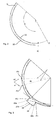
- Fig. 1 shows a rough schematic representation of an apparatus 1 for sterilizing containers according to the internal state of the art of the applicant.
- containers 10 (shown only schematically) between two walls 22 and 32 along a circular transport path T transported here.
- the reference numeral 1 refers to the Device in its entirety.
- this device has two loading devices or radiation devices 4, which act on an outer wall of the containers with radiation, for example with electron radiation.
- a channel is formed within which the plastic preforms 10 are conveyed.
- the device 1 has a transport device (not shown) which transports the containers. It would be conceivable that a rotatable support is provided, are arranged on the gripping elements and / or retaining pins for gripping or holding the containers 10, which are in particular plastic preforms. It would also be conceivable that the inner wall 32 is rotatably arranged on this inner wall, the gripping elements or holding mandrels are arranged.
- the reference numeral 20 refers in its entirety to the shielding device which shields the resulting X-ray radiation, wherein, for example, the outer wall is a component of this shielding device 20.
- the device 1 shown is preferably arranged within a module which has further treatment stations, in particular a further treatment station.
- the plastic preforms preferably pass through the module in such a way that they are sterilized after an inlet star of the apparatus 1 shown on the outside by means of charge carrier radiation, in particular by means of electron beams (but also about protons or alpha particles would be considered).
- the plastic preforms are preferably held by means of an inner gripper on the inner surface and transported through a tunnel-like channel.
- the plastic preforms are preferably guided by means of an aseptic transport star or dividing delay star to a following treatment device (not shown), which sterilizes the plastic preforms (also preferably by means of electron radiation) on their inner side.
- the plastic preforms are held on the outside thereof, while an electron beam emitter is at least partially introduced into the preform.
- an electron beam emitter is at least partially introduced into the preform.
- the preforms are transported out of the module by means of another transport star.
- the devices mentioned within the module are preferably housed in their entirety, so no electron or X-rays can escape.
- radiation traps are arranged, which ensure the frequent deflection of the X-radiation within the module in order to keep the module compact.
- Fig. 2 shows a representation for illustrating a beam path in the in Fig. 1 shown device.
- the reference symbol S refers to the resulting X-radiation, which is reflected here several times and attenuated in this way.
- the reference character a denotes an arc which corresponds to the circumferential angle which is necessary in order to achieve a sufficient attenuation of the X-ray radiation. This results from the angle which lies between three points at which the radiation is reflected three times on the outer wall.
- the reference character B indicates the distance between the two walls 22 and 32 and thus the width of the gap, within which the plastic preforms 10 are transported.
- the reference symbol R denotes a radius of curvature of the inner wall 32. It can be seen that both walls are curved in a circular manner here and preferably in each case as center point have the center of the transport path of the plastic preforms.
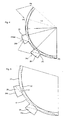
- Fig. 3 shows a schematic representation of the device according to the invention.
- a recess 24 or a radiation trap 24 is disposed on the outer wall 22.
- This recess forms a cavity 26 into which the X-rays S can enter.
- this recess 24 has a radially outwardly widening cross-section. Through this cross section, the efficiency of the recess or the radiation trap 24 can be further improved.
- the reference numerals 22a, 22b, 22c refer to walls which define the cavity and where the resulting X-ray radiation can also be reflected.
- the resulting X-ray radiation could be reflected successively on a plurality of these walls 22a, 22b, 22c.
- the reference symbol da again indicates the angular difference resulting from the two angles a2 and a1 and illustrates the reduction achieved by the insertion of the radiation trap 24.
- Fig. 4 shows a further embodiment of the device according to the invention.
- two recesses 24a, 24b are arranged on or in the outer wall, which each form the cavities 26.
- the reference numeral indicates the angle or the circumferential distance, which can be saved by the presence of these two recesses or beam traps.
- reference character P4 refers to the point where the rays are reflected from the point P0 (ray entrance) for the third time.
- the reference symbol P3 denotes the point which the beams can maximally reach in the presence of the two beam traps, with the reference symbol Pmax in each case designating the point Pmax of the respective maximum reflection point with beam trap.
- Fig. 5 shows a beam path in the device Fig. 4 , wherein here only the ray trajectories are shown, which can result in maximum in the presence of the two recesses.
- the recesses 24a, 24b are arranged in a circumferential direction of the device 1 at a predetermined distance from one another. In this case, this distance can also be selected depending on a circumferential size of the respective recess such that a maximum radiation path of the resulting X-radiation is optimally reduced.
- a ratio between a length l of the two recesses 24a, 24b in the circumferential direction and a distance d between these adjacent recesses is between 1: 2 and 2: 1, preferably between 1: 1.5 and 1.5: 1 and more preferably between 1: 1.2 and 1.2: 1.
- Fig. 6 shows a side view of another embodiment of the device according to the invention. It can be seen here that corresponding recesses are also present in a top wall 36 and a bottom wall 38. Thus, it would be conceivable that the recesses 24 or 24a, 24b described above are designed such that they also extend into the region of the top wall and / or the bottom wall. It can be seen that even by these measures a shortening of the maximum distance to be covered by the radiation up to the third reflection can be achieved.
- the walls are at least partially and preferably completely made of an X-ray shielding material such as lead.
- Radiation devices 4 shown are arranged such that radiation can not reach in any case up to an exit lock and / or an entrance lock of the device.
Landscapes
- Health & Medical Sciences (AREA)
- General Health & Medical Sciences (AREA)
- Epidemiology (AREA)
- Life Sciences & Earth Sciences (AREA)
- Animal Behavior & Ethology (AREA)
- Public Health (AREA)
- Veterinary Medicine (AREA)
- Toxicology (AREA)
- Engineering & Computer Science (AREA)
- Mechanical Engineering (AREA)
- Apparatus For Disinfection Or Sterilisation (AREA)
Applications Claiming Priority (1)
| Application Number | Priority Date | Filing Date | Title |
|---|---|---|---|
| DE102013104998.2A DE102013104998A1 (de) | 2013-05-15 | 2013-05-15 | Vorrichtung und Verfahren zum Sterilisieren von Behältnissen mit Abschirmeinrichtung gegen Röntgenstrahlen |
Publications (2)
| Publication Number | Publication Date |
|---|---|
| EP2803368A1 true EP2803368A1 (fr) | 2014-11-19 |
| EP2803368B1 EP2803368B1 (fr) | 2016-11-16 |
Family
ID=50842000
Family Applications (1)
| Application Number | Title | Priority Date | Filing Date |
|---|---|---|---|
| EP14001716.1A Active EP2803368B1 (fr) | 2013-05-15 | 2014-05-15 | Dispositif et procédé destinés à la stérilisation de récipients dotés de dispositif de blindage contre les rayons X |
Country Status (5)
| Country | Link |
|---|---|
| US (1) | US9511158B2 (fr) |
| EP (1) | EP2803368B1 (fr) |
| JP (2) | JP2014223297A (fr) |
| CN (1) | CN104162177B (fr) |
| DE (1) | DE102013104998A1 (fr) |
Cited By (1)
| Publication number | Priority date | Publication date | Assignee | Title |
|---|---|---|---|---|
| WO2016114108A1 (fr) * | 2015-01-14 | 2016-07-21 | Hitachi Zosen Corporation | Système de stérilisation par faisceau d'électrons ayant des émetteurs de stérilisation externes non-fixes se déplaçant par rapport à des objets de stérilisation |
Families Citing this family (1)
| Publication number | Priority date | Publication date | Assignee | Title |
|---|---|---|---|---|
| DE102020107571B4 (de) | 2020-03-19 | 2024-07-18 | Ledvance Gmbh | Leuchtvorrichtung und die Leuchtvorrichtung umfassendes Beleuchtungssystem |
Citations (6)
| Publication number | Priority date | Publication date | Assignee | Title |
|---|---|---|---|---|
| EP2371397A1 (fr) * | 2010-03-23 | 2011-10-05 | Krones AG | Dispositif de stérilisation de récipients |
| EP2594493A2 (fr) * | 2011-11-21 | 2013-05-22 | Krones AG | Dispositif de stérilisation intérieure et extérieure de récipients en plastique au moyen du rayonnement d'un support de chargement et méthod et ligne de traitement correspondant |
| WO2013092735A1 (fr) * | 2011-12-19 | 2013-06-27 | Krones Ag | Dispositif et procédé permettant de stériliser des récipients avec surveillance de fonctionnement |
| EP2724731A1 (fr) * | 2012-10-23 | 2014-04-30 | Krones AG | Dispositif de stérilisation extérieure d'ébauches en plastique |
| EP2769740A1 (fr) * | 2011-10-17 | 2014-08-27 | Hitachi Zosen Corporation | Structure de blindage pour équipement de stérilisation par faisceaux d'électrons |
| EP2769922A1 (fr) * | 2011-10-17 | 2014-08-27 | Hitachi Zosen Corporation | Équipement de stérilisation par faisceaux électroniques pour contenants au moyen d'un dispositif de transport pivotant |
Family Cites Families (14)
| Publication number | Priority date | Publication date | Assignee | Title |
|---|---|---|---|---|
| US2336443A (en) | 1941-04-04 | 1943-12-07 | Standard Railway Devices Co | Refrigerator car construction |
| US4025294A (en) | 1974-05-24 | 1977-05-24 | Beloit Corporation | Parison oven |
| JPH0355599U (fr) * | 1989-10-04 | 1991-05-29 | ||
| US6285030B1 (en) * | 1997-05-09 | 2001-09-04 | The Titan Corporation | Article irradiation system in which article transporting conveyor is closely encompassed by shielding material |
| JPH11248892A (ja) | 1998-02-27 | 1999-09-17 | Mitsubishi Heavy Ind Ltd | 電子線照射方法及びその装置 |
| CA2443150A1 (fr) | 2001-04-02 | 2002-10-10 | Mitec Incorporated | Systeme et procede d'irradiation |
| ITMO20070137A1 (it) * | 2007-04-18 | 2008-10-19 | Maria Prudenziati | Sistema innovativo integrato, flessibile e totalmente computerizzato per la produzione e la sterilizzazione di preforme e/o bottiglie in pet di forma e dimensioni diverse, loro sigillatura e marchiatura. |
| EP1982920A1 (fr) | 2007-04-19 | 2008-10-22 | Krones AG | Dispositif de stérilisation de récipients |
| DE102008007428B4 (de) | 2008-02-01 | 2016-02-11 | Khs Gmbh | Verfahren sowie Vorrichtung zum Sterilisieren von Packmitteln |
| US8293173B2 (en) * | 2009-04-30 | 2012-10-23 | Hitachi Zosen Corporation | Electron beam sterilization apparatus |
| DE102009040363A1 (de) * | 2009-09-07 | 2011-03-10 | Krones Ag | Vorrichtung und Verfahren zum Herstellen von Kunststoffflaschen |
| DE102010034895A1 (de) | 2010-08-19 | 2012-02-23 | Krones Aktiengesellschaft | Vorrichtung zum Behandeln von Verpackungen |
| DE102011012342A1 (de) | 2011-02-24 | 2012-08-30 | Krones Aktiengesellschaft | Verfahren und Vorrichtung zur Sterilisation von Behältnissen |
| DE102011013121A1 (de) | 2011-03-04 | 2012-09-20 | Krones Aktiengesellschaft | Blasformmaschine mit Sterilraum und Beheizung |
-
2013
- 2013-05-15 DE DE102013104998.2A patent/DE102013104998A1/de not_active Withdrawn
-
2014
- 2014-04-24 JP JP2014090475A patent/JP2014223297A/ja not_active Withdrawn
- 2014-05-09 CN CN201410195980.5A patent/CN104162177B/zh active Active
- 2014-05-09 US US14/274,478 patent/US9511158B2/en active Active
- 2014-05-15 EP EP14001716.1A patent/EP2803368B1/fr active Active
-
2018
- 2018-10-18 JP JP2018196580A patent/JP6932115B2/ja active Active
Patent Citations (6)
| Publication number | Priority date | Publication date | Assignee | Title |
|---|---|---|---|---|
| EP2371397A1 (fr) * | 2010-03-23 | 2011-10-05 | Krones AG | Dispositif de stérilisation de récipients |
| EP2769740A1 (fr) * | 2011-10-17 | 2014-08-27 | Hitachi Zosen Corporation | Structure de blindage pour équipement de stérilisation par faisceaux d'électrons |
| EP2769922A1 (fr) * | 2011-10-17 | 2014-08-27 | Hitachi Zosen Corporation | Équipement de stérilisation par faisceaux électroniques pour contenants au moyen d'un dispositif de transport pivotant |
| EP2594493A2 (fr) * | 2011-11-21 | 2013-05-22 | Krones AG | Dispositif de stérilisation intérieure et extérieure de récipients en plastique au moyen du rayonnement d'un support de chargement et méthod et ligne de traitement correspondant |
| WO2013092735A1 (fr) * | 2011-12-19 | 2013-06-27 | Krones Ag | Dispositif et procédé permettant de stériliser des récipients avec surveillance de fonctionnement |
| EP2724731A1 (fr) * | 2012-10-23 | 2014-04-30 | Krones AG | Dispositif de stérilisation extérieure d'ébauches en plastique |
Cited By (1)
| Publication number | Priority date | Publication date | Assignee | Title |
|---|---|---|---|---|
| WO2016114108A1 (fr) * | 2015-01-14 | 2016-07-21 | Hitachi Zosen Corporation | Système de stérilisation par faisceau d'électrons ayant des émetteurs de stérilisation externes non-fixes se déplaçant par rapport à des objets de stérilisation |
Also Published As
| Publication number | Publication date |
|---|---|
| EP2803368B1 (fr) | 2016-11-16 |
| DE102013104998A1 (de) | 2014-11-20 |
| CN104162177A (zh) | 2014-11-26 |
| US20140341353A1 (en) | 2014-11-20 |
| US9511158B2 (en) | 2016-12-06 |
| JP2019034182A (ja) | 2019-03-07 |
| JP2014223297A (ja) | 2014-12-04 |
| CN104162177B (zh) | 2017-03-29 |
| JP6932115B2 (ja) | 2021-09-08 |
Similar Documents
| Publication | Publication Date | Title |
|---|---|---|
| EP2594493B1 (fr) | Dispositif de stérilisation intérieure et extérieure de préforms au moyen du rayonnement d'un support de chargement et méthod et ligne de traitement correspondant | |
| EP2371397B1 (fr) | Dispositif de stérilisation de récipients | |
| EP2604410B1 (fr) | Dispositif de déformation d'ébauches en plastique, installation de remplissage de boissons et procédé | |
| EP2845609B1 (fr) | Dispositif et procédé de stérilisation de récipients avec une possibilité d'entretien | |
| EP2724731B1 (fr) | Dispositif de stérilisation extérieure des conteneurs plastiques | |
| EP2594495B1 (fr) | Dispositif, système et méthode avec elément de support à accroche intérieure pour la stérilisation de récipients au moyens de faisceaux d'électrons | |
| EP2183026B1 (fr) | Équipement de thérapie particulaire | |
| DE102012103116A1 (de) | Vorrichtung und Verfahren zum strahlungsbasierten Sterilisieren von Behältnisverschlüssen | |
| DE102014102537A1 (de) | Vorrichtung und Verfahren zum Sterilisieren von Behältnissen | |
| EP2845610B1 (fr) | Dispositif pour protection contre les rayonnements de stérilisation de récipients | |
| DE102011012342A1 (de) | Verfahren und Vorrichtung zur Sterilisation von Behältnissen | |
| DE102013109988A1 (de) | Vorrichtung zum Sterilisieren von Kunststoffvorformlingen bei gleichzeitiger Innen- und Außensterilisierung | |
| WO2009144114A1 (fr) | Dispositif permettant de stériliser des récipients au moyen de porteurs de charge | |
| EP2803368B1 (fr) | Dispositif et procédé destinés à la stérilisation de récipients dotés de dispositif de blindage contre les rayons X | |
| EP2559444A1 (fr) | Dispositif de stérilisation de récipients en plastique avec dispositif de protection | |
| EP2719399A1 (fr) | Stérilisation de récipients au moyen de faisceaux d'électrons avec protection contre le rayonnement pour les doigts de faisceaux | |
| EP2581096B1 (fr) | Dispositif et procédé de stérilisation de récipients avec source des éléctrons introduite dans les récipients | |
| EP3733217B1 (fr) | Dispositif et procédé de stérilisation de fermetures de récipient | |
| DE102011055005A1 (de) | Vorrichtung zum Sterilisieren von Kunststoffbehältnissen mittels mediengesteuerter Elektronenstrahlen | |
| EP2512596B1 (fr) | Appareil médical à rayons x et procédé de fonctionnement | |
| DE202012103519U1 (de) | Vorrichtung zum Sterilisieren von Behältnissen mit Aufbereitung für Kühlmedium | |
| DE102023116964A1 (de) | Vorrichtung und Verfahren zum Behandeln und insbesondere Sterilisieren von Behältnissen | |
| DE102015002014A1 (de) | Vorrichtung und Verfahren zum Sterilisieren von Fördermitteln wie insbesondere Transportbändern | |
| EP4663209A1 (fr) | Procédé de transfert en série d'objets à travers une chambre de traitement pour un traitement ultérieur dans un confinement dans des conditions aseptiques et installation de production correspondante | |
| DE102013101371A1 (de) | Vorrichtung zum Sterilisieren von Behältnissen mit Magnetfeldabschirmung |
Legal Events
| Date | Code | Title | Description |
|---|---|---|---|
| PUAI | Public reference made under article 153(3) epc to a published international application that has entered the european phase |
Free format text: ORIGINAL CODE: 0009012 |
|
| 17P | Request for examination filed |
Effective date: 20140515 |
|
| AK | Designated contracting states |
Kind code of ref document: A1 Designated state(s): AL AT BE BG CH CY CZ DE DK EE ES FI FR GB GR HR HU IE IS IT LI LT LU LV MC MK MT NL NO PL PT RO RS SE SI SK SM TR |
|
| AX | Request for extension of the european patent |
Extension state: BA ME |
|
| R17P | Request for examination filed (corrected) |
Effective date: 20150519 |
|
| RBV | Designated contracting states (corrected) |
Designated state(s): AL AT BE BG CH CY CZ DE DK EE ES FI FR GB GR HR HU IE IS IT LI LT LU LV MC MK MT NL NO PL PT RO RS SE SI SK SM TR |
|
| 17Q | First examination report despatched |
Effective date: 20150804 |
|
| GRAP | Despatch of communication of intention to grant a patent |
Free format text: ORIGINAL CODE: EPIDOSNIGR1 |
|
| INTG | Intention to grant announced |
Effective date: 20151221 |
|
| GRAS | Grant fee paid |
Free format text: ORIGINAL CODE: EPIDOSNIGR3 |
|
| GRAP | Despatch of communication of intention to grant a patent |
Free format text: ORIGINAL CODE: EPIDOSNIGR1 |
|
| INTG | Intention to grant announced |
Effective date: 20160621 |
|
| GRAA | (expected) grant |
Free format text: ORIGINAL CODE: 0009210 |
|
| AK | Designated contracting states |
Kind code of ref document: B1 Designated state(s): AL AT BE BG CH CY CZ DE DK EE ES FI FR GB GR HR HU IE IS IT LI LT LU LV MC MK MT NL NO PL PT RO RS SE SI SK SM TR |
|
| REG | Reference to a national code |
Ref country code: GB Ref legal event code: FG4D Free format text: NOT ENGLISH |
|
| REG | Reference to a national code |
Ref country code: CH Ref legal event code: EP |
|
| REG | Reference to a national code |
Ref country code: IE Ref legal event code: FG4D Free format text: LANGUAGE OF EP DOCUMENT: GERMAN |
|
| REG | Reference to a national code |
Ref country code: AT Ref legal event code: REF Ref document number: 845290 Country of ref document: AT Kind code of ref document: T Effective date: 20161215 |
|
| REG | Reference to a national code |
Ref country code: DE Ref legal event code: R096 Ref document number: 502014001936 Country of ref document: DE |
|
| REG | Reference to a national code |
Ref country code: DE Ref legal event code: R096 Ref document number: 502014001936 Country of ref document: DE |
|
| PG25 | Lapsed in a contracting state [announced via postgrant information from national office to epo] |
Ref country code: LV Free format text: LAPSE BECAUSE OF FAILURE TO SUBMIT A TRANSLATION OF THE DESCRIPTION OR TO PAY THE FEE WITHIN THE PRESCRIBED TIME-LIMIT Effective date: 20161116 |
|
| REG | Reference to a national code |
Ref country code: NL Ref legal event code: MP Effective date: 20161116 |
|
| REG | Reference to a national code |
Ref country code: LT Ref legal event code: MG4D |
|
| REG | Reference to a national code |
Ref country code: FR Ref legal event code: PLFP Year of fee payment: 4 |
|
| PG25 | Lapsed in a contracting state [announced via postgrant information from national office to epo] |
Ref country code: GR Free format text: LAPSE BECAUSE OF FAILURE TO SUBMIT A TRANSLATION OF THE DESCRIPTION OR TO PAY THE FEE WITHIN THE PRESCRIBED TIME-LIMIT Effective date: 20170217 Ref country code: NO Free format text: LAPSE BECAUSE OF FAILURE TO SUBMIT A TRANSLATION OF THE DESCRIPTION OR TO PAY THE FEE WITHIN THE PRESCRIBED TIME-LIMIT Effective date: 20170216 Ref country code: LT Free format text: LAPSE BECAUSE OF FAILURE TO SUBMIT A TRANSLATION OF THE DESCRIPTION OR TO PAY THE FEE WITHIN THE PRESCRIBED TIME-LIMIT Effective date: 20161116 Ref country code: NL Free format text: LAPSE BECAUSE OF FAILURE TO SUBMIT A TRANSLATION OF THE DESCRIPTION OR TO PAY THE FEE WITHIN THE PRESCRIBED TIME-LIMIT Effective date: 20161116 Ref country code: SE Free format text: LAPSE BECAUSE OF FAILURE TO SUBMIT A TRANSLATION OF THE DESCRIPTION OR TO PAY THE FEE WITHIN THE PRESCRIBED TIME-LIMIT Effective date: 20161116 |
|
| PG25 | Lapsed in a contracting state [announced via postgrant information from national office to epo] |
Ref country code: HR Free format text: LAPSE BECAUSE OF FAILURE TO SUBMIT A TRANSLATION OF THE DESCRIPTION OR TO PAY THE FEE WITHIN THE PRESCRIBED TIME-LIMIT Effective date: 20161116 Ref country code: PL Free format text: LAPSE BECAUSE OF FAILURE TO SUBMIT A TRANSLATION OF THE DESCRIPTION OR TO PAY THE FEE WITHIN THE PRESCRIBED TIME-LIMIT Effective date: 20161116 Ref country code: PT Free format text: LAPSE BECAUSE OF FAILURE TO SUBMIT A TRANSLATION OF THE DESCRIPTION OR TO PAY THE FEE WITHIN THE PRESCRIBED TIME-LIMIT Effective date: 20170316 Ref country code: ES Free format text: LAPSE BECAUSE OF FAILURE TO SUBMIT A TRANSLATION OF THE DESCRIPTION OR TO PAY THE FEE WITHIN THE PRESCRIBED TIME-LIMIT Effective date: 20161116 Ref country code: FI Free format text: LAPSE BECAUSE OF FAILURE TO SUBMIT A TRANSLATION OF THE DESCRIPTION OR TO PAY THE FEE WITHIN THE PRESCRIBED TIME-LIMIT Effective date: 20161116 Ref country code: RS Free format text: LAPSE BECAUSE OF FAILURE TO SUBMIT A TRANSLATION OF THE DESCRIPTION OR TO PAY THE FEE WITHIN THE PRESCRIBED TIME-LIMIT Effective date: 20161116 |
|
| PG25 | Lapsed in a contracting state [announced via postgrant information from national office to epo] |
Ref country code: CZ Free format text: LAPSE BECAUSE OF FAILURE TO SUBMIT A TRANSLATION OF THE DESCRIPTION OR TO PAY THE FEE WITHIN THE PRESCRIBED TIME-LIMIT Effective date: 20161116 Ref country code: RO Free format text: LAPSE BECAUSE OF FAILURE TO SUBMIT A TRANSLATION OF THE DESCRIPTION OR TO PAY THE FEE WITHIN THE PRESCRIBED TIME-LIMIT Effective date: 20161116 Ref country code: EE Free format text: LAPSE BECAUSE OF FAILURE TO SUBMIT A TRANSLATION OF THE DESCRIPTION OR TO PAY THE FEE WITHIN THE PRESCRIBED TIME-LIMIT Effective date: 20161116 Ref country code: DK Free format text: LAPSE BECAUSE OF FAILURE TO SUBMIT A TRANSLATION OF THE DESCRIPTION OR TO PAY THE FEE WITHIN THE PRESCRIBED TIME-LIMIT Effective date: 20161116 Ref country code: SK Free format text: LAPSE BECAUSE OF FAILURE TO SUBMIT A TRANSLATION OF THE DESCRIPTION OR TO PAY THE FEE WITHIN THE PRESCRIBED TIME-LIMIT Effective date: 20161116 |
|
| REG | Reference to a national code |
Ref country code: DE Ref legal event code: R097 Ref document number: 502014001936 Country of ref document: DE |
|
| PG25 | Lapsed in a contracting state [announced via postgrant information from national office to epo] |
Ref country code: BG Free format text: LAPSE BECAUSE OF FAILURE TO SUBMIT A TRANSLATION OF THE DESCRIPTION OR TO PAY THE FEE WITHIN THE PRESCRIBED TIME-LIMIT Effective date: 20170216 Ref country code: LU Free format text: LAPSE BECAUSE OF NON-PAYMENT OF DUE FEES Effective date: 20170531 Ref country code: SM Free format text: LAPSE BECAUSE OF FAILURE TO SUBMIT A TRANSLATION OF THE DESCRIPTION OR TO PAY THE FEE WITHIN THE PRESCRIBED TIME-LIMIT Effective date: 20161116 |
|
| PLBE | No opposition filed within time limit |
Free format text: ORIGINAL CODE: 0009261 |
|
| STAA | Information on the status of an ep patent application or granted ep patent |
Free format text: STATUS: NO OPPOSITION FILED WITHIN TIME LIMIT |
|
| 26N | No opposition filed |
Effective date: 20170817 |
|
| PG25 | Lapsed in a contracting state [announced via postgrant information from national office to epo] |
Ref country code: SI Free format text: LAPSE BECAUSE OF FAILURE TO SUBMIT A TRANSLATION OF THE DESCRIPTION OR TO PAY THE FEE WITHIN THE PRESCRIBED TIME-LIMIT Effective date: 20161116 |
|
| REG | Reference to a national code |
Ref country code: CH Ref legal event code: PL |
|
| PG25 | Lapsed in a contracting state [announced via postgrant information from national office to epo] |
Ref country code: MC Free format text: LAPSE BECAUSE OF FAILURE TO SUBMIT A TRANSLATION OF THE DESCRIPTION OR TO PAY THE FEE WITHIN THE PRESCRIBED TIME-LIMIT Effective date: 20161116 |
|
| REG | Reference to a national code |
Ref country code: IE Ref legal event code: MM4A |
|
| PG25 | Lapsed in a contracting state [announced via postgrant information from national office to epo] |
Ref country code: LI Free format text: LAPSE BECAUSE OF NON-PAYMENT OF DUE FEES Effective date: 20170531 Ref country code: CH Free format text: LAPSE BECAUSE OF NON-PAYMENT OF DUE FEES Effective date: 20170531 |
|
| PG25 | Lapsed in a contracting state [announced via postgrant information from national office to epo] |
Ref country code: LU Free format text: LAPSE BECAUSE OF NON-PAYMENT OF DUE FEES Effective date: 20170515 |
|
| REG | Reference to a national code |
Ref country code: FR Ref legal event code: PLFP Year of fee payment: 5 |
|
| REG | Reference to a national code |
Ref country code: BE Ref legal event code: MM Effective date: 20170531 |
|
| PG25 | Lapsed in a contracting state [announced via postgrant information from national office to epo] |
Ref country code: IE Free format text: LAPSE BECAUSE OF NON-PAYMENT OF DUE FEES Effective date: 20170515 |
|
| PG25 | Lapsed in a contracting state [announced via postgrant information from national office to epo] |
Ref country code: BE Free format text: LAPSE BECAUSE OF NON-PAYMENT OF DUE FEES Effective date: 20170531 |
|
| PG25 | Lapsed in a contracting state [announced via postgrant information from national office to epo] |
Ref country code: MT Free format text: LAPSE BECAUSE OF FAILURE TO SUBMIT A TRANSLATION OF THE DESCRIPTION OR TO PAY THE FEE WITHIN THE PRESCRIBED TIME-LIMIT Effective date: 20161116 |
|
| GBPC | Gb: european patent ceased through non-payment of renewal fee |
Effective date: 20180515 |
|
| PG25 | Lapsed in a contracting state [announced via postgrant information from national office to epo] |
Ref country code: GB Free format text: LAPSE BECAUSE OF NON-PAYMENT OF DUE FEES Effective date: 20180515 |
|
| PG25 | Lapsed in a contracting state [announced via postgrant information from national office to epo] |
Ref country code: HU Free format text: LAPSE BECAUSE OF FAILURE TO SUBMIT A TRANSLATION OF THE DESCRIPTION OR TO PAY THE FEE WITHIN THE PRESCRIBED TIME-LIMIT; INVALID AB INITIO Effective date: 20140515 |
|
| PG25 | Lapsed in a contracting state [announced via postgrant information from national office to epo] |
Ref country code: CY Free format text: LAPSE BECAUSE OF FAILURE TO SUBMIT A TRANSLATION OF THE DESCRIPTION OR TO PAY THE FEE WITHIN THE PRESCRIBED TIME-LIMIT Effective date: 20161116 |
|
| PG25 | Lapsed in a contracting state [announced via postgrant information from national office to epo] |
Ref country code: MK Free format text: LAPSE BECAUSE OF FAILURE TO SUBMIT A TRANSLATION OF THE DESCRIPTION OR TO PAY THE FEE WITHIN THE PRESCRIBED TIME-LIMIT Effective date: 20161116 |
|
| PG25 | Lapsed in a contracting state [announced via postgrant information from national office to epo] |
Ref country code: TR Free format text: LAPSE BECAUSE OF FAILURE TO SUBMIT A TRANSLATION OF THE DESCRIPTION OR TO PAY THE FEE WITHIN THE PRESCRIBED TIME-LIMIT Effective date: 20161116 |
|
| PG25 | Lapsed in a contracting state [announced via postgrant information from national office to epo] |
Ref country code: AL Free format text: LAPSE BECAUSE OF FAILURE TO SUBMIT A TRANSLATION OF THE DESCRIPTION OR TO PAY THE FEE WITHIN THE PRESCRIBED TIME-LIMIT Effective date: 20161116 Ref country code: IS Free format text: LAPSE BECAUSE OF FAILURE TO SUBMIT A TRANSLATION OF THE DESCRIPTION OR TO PAY THE FEE WITHIN THE PRESCRIBED TIME-LIMIT Effective date: 20170316 |
|
| REG | Reference to a national code |
Ref country code: AT Ref legal event code: MM01 Ref document number: 845290 Country of ref document: AT Kind code of ref document: T Effective date: 20190515 |
|
| PG25 | Lapsed in a contracting state [announced via postgrant information from national office to epo] |
Ref country code: AT Free format text: LAPSE BECAUSE OF NON-PAYMENT OF DUE FEES Effective date: 20190515 |
|
| REG | Reference to a national code |
Ref country code: FR Ref legal event code: PLFP Year of fee payment: 10 |
|
| P01 | Opt-out of the competence of the unified patent court (upc) registered |
Effective date: 20230523 |
|
| PGFP | Annual fee paid to national office [announced via postgrant information from national office to epo] |
Ref country code: DE Payment date: 20250402 Year of fee payment: 12 |
|
| PGFP | Annual fee paid to national office [announced via postgrant information from national office to epo] |
Ref country code: IT Payment date: 20250422 Year of fee payment: 12 |
|
| PGFP | Annual fee paid to national office [announced via postgrant information from national office to epo] |
Ref country code: FR Payment date: 20250401 Year of fee payment: 12 |