EP2803447A1 - Dispositif d'outil manuel - Google Patents
Dispositif d'outil manuel Download PDFInfo
- Publication number
- EP2803447A1 EP2803447A1 EP20140161634 EP14161634A EP2803447A1 EP 2803447 A1 EP2803447 A1 EP 2803447A1 EP 20140161634 EP20140161634 EP 20140161634 EP 14161634 A EP14161634 A EP 14161634A EP 2803447 A1 EP2803447 A1 EP 2803447A1
- Authority
- EP
- European Patent Office
- Prior art keywords
- racket
- percussion
- spindle
- tool
- hand tool
- Prior art date
- Legal status (The legal status is an assumption and is not a legal conclusion. Google has not performed a legal analysis and makes no representation as to the accuracy of the status listed.)
- Granted
Links
Images






Classifications
-
- B—PERFORMING OPERATIONS; TRANSPORTING
- B25—HAND TOOLS; PORTABLE POWER-DRIVEN TOOLS; MANIPULATORS
- B25D—PERCUSSIVE TOOLS
- B25D16/00—Portable percussive machines with superimposed rotation, the rotational movement of the output shaft of a motor being modified to generate axial impacts on the tool bit
-
- B—PERFORMING OPERATIONS; TRANSPORTING
- B25—HAND TOOLS; PORTABLE POWER-DRIVEN TOOLS; MANIPULATORS
- B25D—PERCUSSIVE TOOLS
- B25D11/00—Portable percussive tools with electromotor or other motor drive
- B25D11/06—Means for driving the impulse member
- B25D11/10—Means for driving the impulse member comprising a cam mechanism
- B25D11/102—Means for driving the impulse member comprising a cam mechanism the rotating axis of the cam member being coaxial with the axis of the tool
- B25D11/104—Means for driving the impulse member comprising a cam mechanism the rotating axis of the cam member being coaxial with the axis of the tool with rollers or balls as cam surface
-
- B—PERFORMING OPERATIONS; TRANSPORTING
- B25—HAND TOOLS; PORTABLE POWER-DRIVEN TOOLS; MANIPULATORS
- B25D—PERCUSSIVE TOOLS
- B25D11/00—Portable percussive tools with electromotor or other motor drive
- B25D11/02—Portable percussive tools with electromotor or other motor drive in which the tool is connected to an impulse member
-
- B—PERFORMING OPERATIONS; TRANSPORTING
- B25—HAND TOOLS; PORTABLE POWER-DRIVEN TOOLS; MANIPULATORS
- B25D—PERCUSSIVE TOOLS
- B25D16/00—Portable percussive machines with superimposed rotation, the rotational movement of the output shaft of a motor being modified to generate axial impacts on the tool bit
- B25D16/003—Clutches specially adapted therefor
-
- B—PERFORMING OPERATIONS; TRANSPORTING
- B25—HAND TOOLS; PORTABLE POWER-DRIVEN TOOLS; MANIPULATORS
- B25D—PERCUSSIVE TOOLS
- B25D17/00—Details of, or accessories for, portable power-driven percussive tools
-
- B—PERFORMING OPERATIONS; TRANSPORTING
- B25—HAND TOOLS; PORTABLE POWER-DRIVEN TOOLS; MANIPULATORS
- B25D—PERCUSSIVE TOOLS
- B25D17/00—Details of, or accessories for, portable power-driven percussive tools
- B25D17/06—Hammer pistons; Anvils ; Guide-sleeves for pistons
-
- B—PERFORMING OPERATIONS; TRANSPORTING
- B25—HAND TOOLS; PORTABLE POWER-DRIVEN TOOLS; MANIPULATORS
- B25D—PERCUSSIVE TOOLS
- B25D2216/00—Details of portable percussive machines with superimposed rotation, the rotational movement of the output shaft of a motor being modified to generate axial impacts on the tool bit
- B25D2216/0007—Details of percussion or rotation modes
- B25D2216/0023—Tools having a percussion-and-rotation mode
-
- B—PERFORMING OPERATIONS; TRANSPORTING
- B25—HAND TOOLS; PORTABLE POWER-DRIVEN TOOLS; MANIPULATORS
- B25D—PERCUSSIVE TOOLS
- B25D2216/00—Details of portable percussive machines with superimposed rotation, the rotational movement of the output shaft of a motor being modified to generate axial impacts on the tool bit
- B25D2216/0007—Details of percussion or rotation modes
- B25D2216/0038—Tools having a rotation-only mode
-
- B—PERFORMING OPERATIONS; TRANSPORTING
- B25—HAND TOOLS; PORTABLE POWER-DRIVEN TOOLS; MANIPULATORS
- B25D—PERCUSSIVE TOOLS
- B25D2250/00—General details of portable percussive tools; Components used in portable percussive tools
- B25D2250/165—Overload clutches, torque limiters
-
- B—PERFORMING OPERATIONS; TRANSPORTING
- B25—HAND TOOLS; PORTABLE POWER-DRIVEN TOOLS; MANIPULATORS
- B25D—PERCUSSIVE TOOLS
- B25D2250/00—General details of portable percussive tools; Components used in portable percussive tools
- B25D2250/371—Use of springs
Definitions
- the invention relates to a hand tool device with a tool spindle and a percussion mechanism which has a racket and at least one cam guide which drives the racket at least in a percussion drilling operation.
- the tool spindle has at least one bearing surface which, in at least one operating state, supports the beater, in particular in a movable manner, at least in the axial direction.
- a “tool spindle” is to be understood in particular as a shaft which transmits a rotational movement from a gear of the hand tool device to an insert tool attachment of the hand tool device.
- the bearing surface causes a radially directed bearing force on the racket.
- the beater is preferably moved in a substantially translatory manner in the direction of impact, while the tool spindle is rotationally driven in the impact drilling operation.
- the tool spindle is formed as a solid shaft.
- the tool spindle could be formed as a hollow shaft.
- a "percussion mechanism” should be understood in particular to mean a device which is intended to generate a shock impulse and in particular to deliver in the direction of an insertion tool.
- the percussion derives the impact pulse advantageous at least in a percussion drilling over the tool spindle and / or in particular over the werkschwfestist the hand tool device to the insert tool on.
- the striking mechanism is intended to translate a rotational movement into a particular translational impact movement.
- the percussion mechanism is not designed as a catch impact mechanism.
- “provided” is intended to be understood in particular specially programmed, designed and / or equipped.
- the term "bat” is to be understood as meaning a means which, at least in the percussion drilling operation, is accelerated, in particular at least essentially translationally, and emits a pulse picked up during the acceleration as impact pulse in the direction of the insertion tool.
- the racket is integrally formed.
- the racket could be formed in several pieces.
- a "curve guide” is to be understood as a device which converts a rotational energy into a stroke generation, at least by means of a specially shaped guide surface, against which at least a percussion drilling operation passes a connecting means into a linear kinetic energy of the racket.
- the percussion mechanism has a percussion spring which stores the linear kinetic energy of the percussion beater.
- the specially shaped surface is an area that limits a guide curve of the curve guide.
- the cam guide is provided to move the racket once in a turn of a percussion spindle of the hand tool device to a beat.
- the cam guide could be provided to move the racket to at least two or advantageously three strokes in one revolution of the percussion spindle. In this case, in particular could be dispensed with a percussion gear stage.
- the cam guide on the racket causes a force directed away from the tool attachment.
- a “connecting means” is to be understood in particular as meaning a means which produces a mechanical coupling between at least one part of the percussion mechanism, in particular a percussion mechanism spindle, which moves in a rotary drilling operation and in particular the linearly moved racket.
- the connecting means is spherical.
- the connecting means could have another form that appears appropriate to the person skilled in the art.
- the connecting means preferably has a diameter greater than 4 mm, advantageously greater than 5 mm, particularly advantageously greater than 6 mm.
- the connecting means has a diameter smaller than 14 mm, advantageously smaller than 10 mm, particularly advantageously smaller than 8 mm.
- a “percussion drilling operation” is to be understood in particular as meaning an operation of the hand tool device, in which the insertion tool rotates during workpiece machining and is driven strikingly.
- a “bearing surface” is to be understood as meaning a surface which, during operation, effects a bearing force perpendicular to the surface on the beater and permits a movement of the beater parallel to the surface.
- the bearing surface is provided so that the racket slides on the surface in the percussion drilling operation.
- the surface has a low roughness.
- the bearing surface is aligned in particular completely parallel to a direction of impact of the racket.
- the bearing surface is formed cylindrical barrel-shaped. The bearing surface preferably contacts the racket in at least one operating state.
- the racket at least substantially surrounds the tool spindle on at least one plane, whereby a large racket mass can be achieved with a small size.
- the phrase "at least substantially enclosing at least one plane" is intended to mean that beams emanating from an axis of the tool spindle and arranged on the plane intersect the racket over an angular range of at least 180 degrees, advantageously at least 270 degrees , Particularly advantageous the club encloses the percussion spindle by 360 degrees.
- the plane is oriented perpendicular to a rotation axis of the tool spindle.
- the percussion mechanism has a percussion spindle with a bearing surface which, in at least one operating state, supports the racket movably, as a result of which a small size is possible.
- a "percussion spindle” is to be understood in particular as meaning a shaft which transmits a rotational movement directly to the curve guide.
- the percussion spindle transmits the rotational movement of a rotational movement driving the insert tool fastening separately to the curved guide.
- the percussion spindle is formed separately from the tool spindle.
- the percussion spindle is designed as a hollow shaft.
- the racket at least substantially encloses the percussion spindle on at least one level, whereby a large racket mass can be achieved with a small size.
- the racket limits an interior of the racket narrowing in the direction of impact inwardly, whereby a simple design of a low tool spindle mass can be achieved.
- an "interior” is to be understood as a space which is arranged on a straight line between at least two points in which the straight line intersects the club.
- the racket completely encloses the interior space on at least one level.
- a "direction of impact” is to be understood in particular as meaning a direction which runs parallel to an axis of rotation of the tool chuck and which is directed by the racket in the direction of the tool chuck.
- the racket has an at least substantially U-shaped cut surface parallel to the direction of impact.
- the tool spindle has at least one impact surface on which the beater strikes, at least in a percussion drilling operation, whereby a particularly simple construction can be achieved.
- a "striking surface” is to be understood in particular as meaning a surface of the tool spindle, through which the beater transmits the impact pulse to the tool spindle in at least one operating state.
- the racket strikes directly on the tool spindle.
- the bat could strike the tool spindle via an anvil.
- the racket has at least part of the curve guide, whereby a particularly small, lightweight and yet powerful percussion can be provided.
- the racket has at least part of the curve guide
- the racket has a surface to which a connecting means of the curve guide directly transfers the energy to generate the striking motion.
- the part of the cam guide, which the racket has is formed as a surface, which fixes the connecting means fixed relative to the racket.
- the part of the cam guide, which has the racket a limited by the surface mounting recess which fixes the connecting means relative to the racket stationary.
- the racket is intended to fasten a connecting means, which in one operation the part the curve guide and another part of the cam guide, in particular the guide curve connects.
- the connecting means and the bat are connected unsprung.
- the connecting means could be at least partially formed integrally with the racket.
- the part of the cam guide, which the racket has could be formed as a guide curve. "Stationary" is to be understood in particular as meaning that an axis of symmetry and / or a center point of the connecting means relative to the racket is at least substantially stationary in a striking operation.
- the impact mechanism has at least one percussion spring, which stores at least part of a striking energy in at least one operating state, whereby a powerful percussion mechanism can be provided structurally simply.
- a "percussion spring” should in particular be understood to mean a spring which, in at least one operating state, effects a force in the impact direction on the racket.
- impact energy should be understood to mean an energy that accelerates the club in front of a strike in the direction of impact.
- store is to be understood in this context, in particular, that the percussion spring absorbs the impact energy at a time and at a later time, in particular by accelerating the racket, delivers to the racket.
- the cam guide biases the percussion spring.
- the percussion spring fastened the racket in at least one operating state in the circumferential direction whereby a particularly cost-effective, lightweight and space-saving design can be achieved.
- the phrase "attached in the circumferential direction" that the percussion spring in at least one operating condition causes a force on the racket, which counteracts a force acting on the racket in the circumferential direction, which causes in particular the cam guide.
- the attachment of the racket by the percussion spring prevents movement of the racket about an axis of rotation of the percussion spindle by more than 360 degrees, advantageously a movement of more than 180 degrees, more preferably a movement of more than 90 degrees.
- a force acting in the circumferential direction is meant in particular a force be, which has at least one component which is aligned perpendicular to a rotational axis of a percussion spindle of the percussion and causes a torque relative to the circumferential direction of the percussion spindle.
- the hand tool device according to the invention should not be limited to the application and embodiment described above.
- the handheld power tool device according to the invention may have a number deviating from a number of individual elements, components and units mentioned herein.
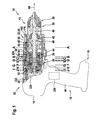
- FIG. 1 shows a hand tool 10.
- the hand tool 10 is designed as a Schlagbohrschraubmaschine.
- the hand tool 10 has a hand tool device 12 according to the invention, a hand tool housing 14 and a battery interface 16.
- the battery interface 16 is provided to supply the hand tool device 12 from a hand tool battery not shown here with an electrical energy.
- the hand tool housing 14 is substantially pistol-shaped. It comprises a handle 18, by means of which an operator holds the hand tool 10 during a work operation.
- the hand tool device 12 comprises a tool guide unit 20, a percussion mechanism 22, a striking stop device 24, a gear 26, a hammer mechanism 28, a drive unit 30, an operating device 32, a torque limiting unit 34 and a spindle blocking device 36.
- the drive unit 30 is designed as an electric motor.
- the transmission 26 is provided to a rotational speed of the drive unit 30 to to reduce. In addition, the transmission 26 is provided to provide at least two different ratios.
- a gripping surface of the handle 18 is formed substantially perpendicular to a rotation axis of the tool guide unit 20.
- the hand tool housing 14 has, on a side facing away from the tool guide unit 20, an overhang relative to the handle 18.
- a basic shape of the hand tool housing 14 is thus T-shaped.
- the tool guide unit 20 includes an insert tool fixture 38 and a tool spindle 40.
- the insert tool fixture 38 and the tool spindle 40 are bolted together.
- the tool attachment 38 and the tool spindle 40 could be detachably connected without tools in a manner that would appear meaningful to a person skilled in the art.
- the insert tool attachment 38 fastens in one operation a not shown here insert tool, such as a drill or a ringbit.
- the insert tool attachment 38 secures the insert tool frictionally.
- an insert tool fastening could fasten the insert tool in a form-fitting manner, for example with an SDS tool chuck or a hexagonal mount.
- the insert tool fixture 38 has three jaws movably mounted by an operator, which secure the insert tool in one operation.
- the insert tool fixture 38 secures the insert tool in one operation axially immovable against the werkschwmaschinebefest Trent 38 and in particular with respect to the tool spindle 40.
- a portion of the werkschwmaschinebefest Trent 38 and the tool spindle 40 are immovably connected relative to each other.
- the insert tool attachment 38 and the tool spindle 40 are screwed together.
- the hand tool device 12 has a bearing means 42 which supports the tool spindle 40 on a side facing the insert tool attachment 38.
- the bearing means 42 supports the tool spindle 40 axially displaceable.
- the bearing means 42 is axially fixedly connected to the tool spindle 40.
- the bearing means 42 is mounted axially movable in the hand tool housing 14.
- the hand tool device 12 has a further bearing means 44, which supports the tool spindle 40 on a side facing the gear 26.
- the bearing means 44 is formed as a sliding bearing.
- the bearing means 44 supports the tool spindle 40 axially displaceable.
- the tool spindle 40 includes a striking surface 46 on which striking mechanism 22 strikes percussion mechanism 22.
- the hand tool housing 14 is designed in several parts.
- the hand tool housing 14 includes a clam shell handle and drive housing 48, a clam shell outer housing 50, a gear housing 52, a percussion gear housing 54 and a striking mechanism housing 56. These parts of the hand tool housing 14 are made separately.
- the handle and drive housing 48 forms the handle 18 and encloses the drive unit 30.
- the outer housing 50 encloses the gear housing 52 and the striking gear housing 54.
- the outer housing 50, the gear housing 52, the striking gear housing 54 and the percussion gear housing 56 positively secured to the handle and Drive housing 48.
- the transmission housing 52 encloses the gear 26. It is tubular.
- the percussion gear housing 54 encloses the percussion gear 28th
- the striking mechanism housing 56 surrounds the hammer mechanism 22. It is also tubular.
- the impact mechanism 22 is switchable to an activated and a deactivated operating state.
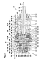
- the percussion mechanism 22 has a racket 58, a percussion spindle 60, a striking mechanism spring 62 and a racket driving device 64.
- the percussion spindle 60 encloses the bearing means 44, which supports the tool spindle 40 on a side facing the gear 26.
- the bearing means 44 is operatively disposed between the tool spindle 40 and the percussion spindle 60.
- the racket 58 is mounted translationally movable in a direction of impact 66. The direction of impact 66 is aligned parallel to an axial direction of the percussion spindle 60.
- the tool spindle 40 and the percussion spindle 60 each have a bearing surface 68, 70, on which the racket 58 is movably mounted.
- the bearing surfaces 68, 70 act directly on the racket 58.
- the bearing surfaces 68, 70 are lateral surfaces of the tool spindle 40 and the percussion spindle 60.
- the racket 58 could only on the tool spindle 40 or on the percussion spindle 60 and possibly on an outside of the Racket 58 be stored.
- An inside of the racket 58 defines an interior space that narrows inward in the direction of impact 66.
- the Bearing surface 68 of the tool spindle 40 acts on a narrowed region of the inside of the racket 58.
- the bearing surface 70 of the percussion spindle 60 acts on a gear 26 facing, unrisen area of the inside of the racket 58.
- the racket 58 has a cup-shaped basic shape, wherein in the ground the cup-shaped basic shape is arranged a recess through which the tool spindle 40 extends.
- the racket 58 strikes the tool spindle 40 when operating with a bottom outside of the cup-shaped basic shape.
- the racket 58 encloses the tool spindle 40 and the percussion spindle 60 on at least one plane aligned perpendicular to the direction of impact 66 by 360 degrees.
- a percussion mechanism could include a racket and a percussion spindle, with the percussion spindle enclosing the racket.
- a curve guide of the impact mechanism would be arranged on an outer side of the racket.
- either the racket or the percussion spindle could have a guide curve of the cam guide.
- FIGS. 3 and 4 show the percussion spindle 60 in two 180 degrees different side views.
- FIG. 5 shows a sectional area A of the racquet drive device 64.
- the racquet drive device 64 has exactly one cam guide 72.
- the cam guide 72 comprises a guide cam 76, a connecting means 78 and a fastening means 80.
- the cam guide 72 is arranged on the percussion spindle 60.
- at least one cam guide could be arranged on a racket.
- the fastener 80 is disposed on the racket 58.
- the racket 58 thus has a portion of the cam guide 72.
- at least one fastening means could be arranged on a percussion spindle.
- the attachment means 80 is formed as a mounting recess for the connection means 78.
- the fastening means 80 is arranged on an inner side of the racket 58.
- the fastening means 80 is introduced into the inside of the racket 58 by means of a bore through a side of the racket 58 facing away from the fastening means.
- the connecting means 78 is formed as a ball.
- the connecting means 78 has a diameter of 7 mm.
- the attachment means 80 stores the connecting means 78 stationary relative to the racket 58.
- the connecting means 78 slides in the Schlagbohr vulgar in the guide cam 76th Die Impact spindle 60 defines a space in which the connecting means 78 moves in the Schlagbohr compassion.
- the percussion spindle 60 is formed as a hollow shaft.
- the striking mechanism spindle 60 is rotatably mounted in the hand tool housing 14 on a side remote from the attachment tool attachment 38.
- the striking mechanism 28 drives the striking mechanism spindle 60.
- the percussion spindle 60 has a toothing 82 on a side facing away from the insert tool attachment 38.
- the guide cam 76 has an impact freewheel region 84, a drum lift region 86 and a mounting recess 88.
- the connecting means 78 is inserted through the mounting recess 88 in the attachment means 80 of the racket 58.
- the percussion spindle 60 rotates clockwise in the percussion drilling operation in the direction of impact 66.
- the impact lift portion 86 is formed in a spiral shape. It extends about 180 degrees about a rotation axis 90 of the percussion spindle 60. The impact lift area 86 moves the connecting means 78 and thus the racket 58 in the impact drilling operation counter to the direction of impact 66.
- the recoil-free region 84 connects two ends 92, 94 of the impact-winding region 86.
- the non-impact region 84 extends about 180 degrees about the axis of rotation 90 of the percussion mechanism spindle 60.
- the impact-free region 84 has a flapping edge 96 which, from the end 92 of the gearbox 26 facing the transmission 26 Schlagetzzugs Schemes 86 starting, approximately parallel to the direction of impact 66 runs.
- the connecting means 78 moves through the hammer-free area 84 without experiencing an axial force until the racket 58 on the Striking surface 46 hits.
- the percussion spring 62 stores in at least one operating state at least a portion of a striking energy that the racket 58 transmits to the tool spindle 40 upon impact.
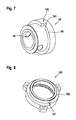
- FIGS. 6 and 7 show the racket 58.
- the percussion spring 62 accelerates the racket 58 against a blow in the direction of impact 66.
- the hand tool housing 14 supports the striking mechanism spring 62 on a side facing away from the racket 58.
- the percussion spring 62 presses directly against the racket 58.
- a substantially annular or helical surface 100 of an annular Anformung 98 to the basic shape of the racket 58 supports the percussion spring 62 from.
- the percussion spring 62 encloses a portion of the racket 58.
- the percussion spring 62 secures the racket 58 in the percussion drilling operation in the circumferential direction.
- the racket 58 has a catching means 102, on which the percussion spring 62 acts in a clockwise direction of the insert tool attachment 38 in a percussion drilling operation in the circumferential direction.
- the percussion spindle 60 rotates in this embodiment in the direction of impact 66 also in a clockwise direction. It is obvious to a person skilled in the art to adapt the catching means 102 to a striking mechanism spindle 60 rotating counter to the clockwise rotation.
- the catching means 102 has a latching surface 104 which is aligned at least substantially perpendicular to the surface 100 of the Anformung 98, to which the percussion spring 62 presses to accelerate the racket 58.
- the surface 100 to which the percussion spring 62 presses to accelerate the racket 58 is ramped and inclined relative to the direction of impact 66.
- the percussion spring 62 acts on the latching surface 104 and connects the racket 58 and the percussion spring 62 in the circumferential direction in a form-fitting manner.
- the percussion spring 62 slips over the latching surface 104.
- the racket 58 and the percussion spring 62 in the counterclockwise rotation of the insert tool attachment 38 freewheeling each other in the circumferential direction.
- the percussion spring 62 could always be rotatably connected to the racket 58 and the percussion spring 62 could have a freewheel in the counterclockwise rotation with respect to the hand tool housing 14.
- FIG. 8 shows, a rotatably connected to the hand tool housing 14 component of the hand tool 10, which here exemplarily has a ring gear 122, a substantially annular or helical surface 106 which supports the percussion spring 62 in a counter to the direction of impact 66 oriented direction.
- the surface 106 is interrupted by a latching surface 107, which is aligned substantially perpendicular to the surface 106 of the component.
- the latching surface 107 is provided to cause a clockwise force in the clockwise direction of the insert tool attachment 38 to the percussion spring 62, which counteracts a movement of the racket 58.
- the latching surface 107 connects the hand tool housing 14 and the percussion spring 62 in the circumferential direction during the clockwise rotation of the insert tool attachment 38 in a form-fitting manner.
- the percussion spring 62 could on a the Stick 58 facing away from rotation to be connected to the hand tool housing 14, for example by one end of a striking mechanism spring 62 forming wire is bent in the direction of the drive unit 30 projecting.
- another component which appears appropriate to a person skilled in the art could have the latching surface 107, for example a housing part of the hand tool housing 14.
- the racket 58 has a ventilation opening 108 through which air can escape during a movement of the racket 58 from a space bounded by the tool spindle 40, the percussion spindle 60 and the racket 58 and / or can flow into the space.
- the percussion gear 28 is disposed between the gear 26 and the striking mechanism 22.
- the striking mechanism 28 has a first planetary gear stage 110.
- the transmission 26 has a second planetary gear stage 112, a third planetary gear stage 114 and a fourth planetary gear stage 116.
- FIG. 9 1 shows a sectional area B of the first planetary gear stage 110.
- the first planetary gear stage 110 increases a first rotational speed of the second planetary gear stage 112 for driving the hammer mechanism 22.
- the second planetary gear stage 114 drives the tool spindle 40 at this first rotational speed.
- the toothing 82 of the striking mechanism spindle 60 forms a sun gear of the first planetary gear stage 110.
- the toothing 82 meshes with planet wheels 118 of the first planetary gear stage 110, which are guided by a planet carrier 120 of the first planetary gear stage 110.
- the ring gear 122 of the first planetary gear stage 110 meshes with the planetary gears 118 of the first planetary gear stage 110.
- the ring gear 122 is non-rotatably connected to the hand tool housing 14.
- the impact shut-off device 24 is provided to turn off the striking mechanism 22 during a screwing operation, a drilling operation and in the impact drilling mode when the insertion tool is unloaded.
- the Schlagabschaltvorraum 24 has three transmission means 128, a control element 130 and a Schlagabschaltkupplung 132.
- FIG. 10 shows an isolated side view of Schlagabschaltvortechnisch 24th
- FIG. 11 shows a sectional area C by the control element 130 of Schlagabschaltvortechnisch 24.
- the shows FIG. 11 a connecting means 124 which rotatably connects the tool spindle 40 and a planet carrier 126 of the second planetary gear stage 112.
- the connecting means 124 connects the tool spindle 40 and the planet carrier 126 of the second planetary gear stage 112 axially displaceable.
- the impact shut-off clutch 132 is disposed between the first planetary gear stage 110 and the second planetary gear stage 112.
- the Schlagabschaltkupplung 132 has a first coupling element 134 which is always rotationally coupled to a part of the impact mechanism 22.
- the first coupling element 134 is non-rotatably connected to the planet carrier 120 of the first planetary gear stage 110.
- the first coupling element 134 is formed integrally with the planet carrier 120 of the first planetary gear stage 110.
- the Schlagabschaltkupplung 132 has a second coupling element 136 which is always rotationally coupled to a portion of the transmission 26.
- the second coupling element 136 is non-rotatably connected to the connecting means 124.
- the second coupling element 136 is integrally formed with the connecting means 124.
- the planet carrier 126 of the second planetary gear stage 112 is rotatably connected to the second coupling element 136. In the illustrated percussion drilling operation, the impact shut-off clutch 132 is closed.
- the tool spindle 40 transmits an axial coupling force to the impact shut-off clutch 132 when the operator presses the insertion tool against a workpiece.
- the clutch force closes the impact shut-off clutch 132.
- a shock-switching spring 140 of the impact shut-off device 24 opens the impact-off clutch 132.
- the transmission means 128 are formed as rods.
- the control member 130 supports the tool guide unit 20 in a screwing and drilling mode in a direction opposite to the direction of impact 66.
- a force applied to the tool guide unit 20 acts via the bearing means 44, another transmission means 142 of the Schlagabschaltvorraum 24 and formed as rods transmission means 128 on support surfaces 144 of the control element 130. This prevents the coupling elements 134, 136 in the screwing and drilling mode engage.
- the further transmission means 142 is substantially star-shaped with an annular disc-shaped central region.
- the control element 130 has three recesses 146. In the illustrated hammering operation, the transfer means 128 are inserted into the recesses 146, whereby the tool guide unit 20 is axially movable in the impact drilling mode.
- the connecting means 128 is operatively disposed between the planet carrier 126 of the second planetary gear stage 112 and the tool spindle 40.
- the connecting means 128, the second coupling element 136 of the Schlagabschaltkupplung 132 The connecting means 128 is mounted axially displaceable against the Schlagschaltfeder 140. By an axial displacement of the connecting means 128 in the direction of the insert tool attachment 38, the Schlagabschaltkupplung 132 is opened.
- the connecting means 128 is always rotationally fixed and axially displaceable connected to the tool spindle 40.
- the planet carrier 126 of the second planetary gear stage 112 remains rotationally coupled to the tool spindle 40 even in the event of a blow.
- the planet carrier 126 of the second planetary gear 112 is rotatably connected to the connecting means 128.
- the planet carrier 126 of the second planetary gear stage 112 and the connecting means 128 are connected axially displaceable relative to each other.
- FIG. 12 12 shows a cutting surface D of the spindle locking device 36.
- the spindle locking device 36 is provided to non-rotatably connect the tool spindle 40 to the hand tool housing 14 when a tool torque is applied to the tool attachment 38, such as when an insert tool is clamped into the tool attachment 38.
- the spindle lock 36 is partially formed integrally with the connecting means 128 and the planet carrier 126 of the second planetary gear 112.
- the spindle locking device 36 has blocking means 150, first clamping surfaces 152, a second clamping surface 154 and free-wheeling surfaces 156.
- the blocking means 150 are formed roller-shaped.
- the first clamping surfaces 152 are formed as areas of a surface of the connecting means 128.
- the first clamping surfaces 152 are flat.
- the second clamping surface 154 is formed as an inner side of a clamping means 158 of the spindle locking device 36.
- the clamping means 158 is designed as a clamping ring.
- the clamping means 158 is non-rotatably connected via a component of the spindle locking device 36 with the hand tool housing 14, with the percussion mechanism housing 56 of the hand tool housing 14.
- the clamping means 158 via a stop means 160 of the spindle locking device 36 rotatably connected to the hand tool housing 14.
- the freewheeling surfaces 156 are formed as regions of a surface of the planet carrier 126 of the second planetary gear stage 112.
- the blocking means clamp 150 between the first clamping surfaces 152 and the second clamping surface 154.
- the freewheeling surfaces 156 guide the blocking means 150 in a circular path and prevent jamming.
- the planetary carrier 126 of the second planetary gear 112 and the connecting means 128 are interlocked with each other game.
- the spindle locking device 36 is disposed outside of the transmission housing 52.
- the spindle locking device 36 is disposed within the hammer mechanism housing 56.
- the torque limiting unit 34 is provided to limit in a screwing mode a maximum of the tool attachment 38 dispensed tool torque.
- the torque limiting unit 34 comprises the abutment means 160, an operating element 162, adjusting elements 164, limiting springs 166, a transmission means 168, first abutment surfaces 170, a second abutment surface 172 and limiting means 174.
- the transmission means 168, the first abutment surfaces 170 and the second abutment surfaces 172 form a coupling the torque limiting unit 34.
- the operating element 162 is annular.
- the operating element 162 is double-shelled.
- the operating element 162 has oblique setting surfaces 176, which act on the adjusting elements 164 in the axial direction.
- the adjusting elements 164 are rotationally fixed and mounted axially displaceable by the operating element 162. A rotation of the operating element 162 displaces the adjusting elements 164 in the axial direction.
- the limiting springs 166 are supported on one side on the adjusting element 164.
- the limiting springs 166 are supported on another side via the transmission means 168 on the abutment means 160 of the torque limiting unit 34.
- the transmission means 168 are mounted displaceably in the axial direction.
- a surface of the abutment means 160 has the first abutment surfaces 170.
- the stop means 160 is movably mounted in the screwing mode in the axial direction against the limiting springs 166.
- the second stopper surface 172 is formed as a portion of a surface of a ring gear 178 of the second planetary gear stage 112.
- the second abutment surface 172 defines trough-shaped recesses 180.
- the limiting means 174 are spherical.
- the torque limiting unit 34 has a limitation means guiding means 182, which is intended to support the limiting means 174 axially displaceable.
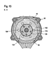
- FIG. 13 shows a sectional area E of the limiting means guiding means 182.
- the limiting means guiding means 182 defines recesses 184 in which the limiting means 174 are slidably mounted in the direction of impact 66.
- the recesses 184 are tubular.
- the hammer mechanism housing 54 rotatably secures the limit means guide means 182.
- the limiting means 174 are arranged in the trough-shaped recesses 180.
- the limiting means 174 fasten the ring gear 178 of the second planetary gear stage 112 in a rotationally fixed manner.
- the limiting means 174 push the abutment means 160 against the limiting springs 166 away.
- the limiting means 174 each jump into a next of the trough-shaped recesses 180.
- the ring gear 178 of the second planetary gear stage 112 rotates, whereby the screwing operation is interrupted.
- the torque limiting unit 34 has shut-off means 186, 188 which are provided to switch off a torque limitation of the torque limiting unit 34, as a result of which a maximum torque is dependent on a maximum torque of the drive unit 30.
- the adjusting element 164 and the transmission means 168 each have a part of the shut-off means 186, 188.
- the shut-off means 186, 188 prevent at least in a drilling mode, an axial movement of the stop means 160.
- the shut-off means 186, 188 are formed as columnar projections on the adjusting element 164 and the transmission means 168.
- the shut-off means 186, 188 extend towards each other.
- the shut-off means 186, 188 are operatively aligned parallel to the limiting springs 166.
- shut-off means 186, 188 prevent an axial displacement of the stop means 160.
- the adjusting element 164 is displaced so far in the direction of the transmission means 168 that the shut-off means 186, 188 abut each other.
- FIG. 14 shows a sectional area F of the second planetary gear stage 112.
- the ring gear 178 of the second planetary gear stage 112 is stored at least in a drilling operation against a complete rotation in the hand tool housing 14.
- Planetary gears 190 of the second planetary gear stage 112 mesh with the ring gear 178 and a sun gear 192 of the second planetary gear stage 112.
- FIG. 15 shows a sectional area G by a planet carrier 194 of the third planetary gear stage 114th
- FIG. 16 shows a sectional area H by planetary gears 196 of the third planetary gear stage 114.
- the sun gear 192 of the second planetary gear 112 is rotatably connected to the planet carrier 194 of the third planetary gear stage 114.
- Planetary gears 196 of the third planetary gear stage 114 mesh with a sun gear 198 and a ring gear 200 of the third planetary gear stage 114.
- the ring gear 200 of the third planetary gear stage 114 has a toothing 202, which rotatably connects the ring gear 200 of the third planetary gear stage 114 in a first translation with the hand tool housing 14.
- the toothing 202 of the ring gear 200 of the third planetary gear stage 114 engages in the first translation in an internal toothing of a ring 204, which in turn is rotatably connected to the hand tool housing 14.
- a support means 206 is arranged, which is intended to derive an axially acting on the ring gear 200 of the third planetary gear stage 114, in particular by the torque limiting unit 34 acting force on the hand tool housing 14.
- the support means 206 is formed annular disk-shaped.
- the support means 206 is positively connected to the hand tool housing 14 via the ring 204 in an axial direction pointing away from the insert tool attachment 38.
- a snap ring 208 secures the support means 206 in an axial direction to be pointed to the insert tool fixture 38.
- FIG. 17 shows a sectional area I by a planet carrier 210 of the fourth planetary gear stage 116th
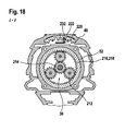
- FIG. 18 shows a sectional area J by planetary gears 212 of the fourth planetary gear stage 116.
- the sun gear 198 of the third planetary gear stage 114 is rotatably connected to the planet carrier 210 of the fourth planetary gear stage 116.
- the planet gears 212 of the fourth planetary gear stage 116 mesh with a sun gear 214 and a ring gear 216 of the fourth planetary gear stage 116.
- the ring gear 216 of the fourth planetary gear stage 116 is rotatably connected to the hand tool housing 14.
- the ring gear 216 of the fourth planetary gear stage 116 is integrally formed with a gear housing cover 218 facing away from the insert tool attachment 38.
- the gear housing cover 218 may be formed integrally with the gear housing 52, but here is formed separately.
- the transmission housing cover 218 is prior to assembly of the transmission housing 52 connected to the transmission 26 to the transmission housing 52.
- the sun gear 214 of the fourth planetary gear stage 116 is rotatably connected to a rotor 220 of the drive unit 30.
- the ring gear 200 of the third planetary gear stage 114 is as in FIG FIG. 2 shown slidably mounted in the axial direction.
- the ring gear 200 of the third planetary gear stage 114 is rotatably connected to the hand tool housing 14.
- the ring gear 200 of the third planetary gear stage 114 is rotatably connected to the planet carrier 210 of the fourth planetary gear stage 116 and rotatably supported relative to the hand tool housing 14.
- the planet carrier 210 of the fourth planetary gear stage 116 has an outer toothing.
- a reduction ratio of the first gear ratio between the rotor 220 of the drive unit 30 and the planet carrier 194 of the third planetary gear stage 114, which is greater than a reduction ratio of the second gear ratio results.
- the insert tool fixture 38 rotates slower at the maximum speed of the drive unit 30 in the first ratio than in the second ratio.
- a maximum of the drive unit 30 at the insert tool attachment 38 can be effected torque is greater in the first translation than in the second translation.
- a torque which can be maximally effected by the drive unit 30 at the attachment tool attachment 38 in the first ratio is 40 Nm.
- a torque which can be maximally effected by the drive unit 30 at the attachment tool attachment 38 in the second ratio is 14 Nm.
- the transmission case cover 218 is formed of a plastic.
- the gear housing cover 218 closes the gear housing 52 on the side facing away from the tool attachment 38 side.
- the torque limiting unit 34 is provided to close the side of the gear housing 52 facing the insert tool attachment 38 in a ready-to-operate state.
- the percussion gear housing 54 attached to the gear housing 52, the component of the torque limiting unit 34, which closes the the werkzeugbefest Trent 38 facing side of the gear housing 52 in an operational state.
- the limiting means guiding means 182 of the torque limiting unit 34 closes the side of the gear housing 52 facing the insert tool attachment 38 in an operational state.
- the limiting means guide means 182 is formed of a metallic material.
- the transmission housing 52 is of a the insert tool attachment 38 side facing at least the second, third and fourth planetary gear 112, 114, 116 of the transmission 26 equipped.
- the operating device 32 has a first operating element 222 and a second operating element 224.
- the first operating element 222 is arranged on a side facing away from the handle 18 of the hand tool housing 14. It is mounted movable parallel to the axial direction of the transmission 26.
- the first operating element 222 is connected via an adjusting means 226 of the operating device 32 in the axial direction with the ring gear 200 of the third planetary gear stage 114.
- the ring gear 200 of the third planetary gear stage 114 has a groove 228 into which the adjusting means 226 engages.
- the ring gear 200 of the third planetary gear stage 114 is connected to the adjusting means 226 relative to the adjusting means 226 axially rotatable in the axial direction.
- the adjusting means 226 is resilient, whereby the translation of a rotational position of the ring gear 200 of the third planetary gear stage 114 can be adjusted independently.
- the first operating member 222 is slid toward the insert tool fixture 38, the first translation is adjusted.
- the second gear is adjusted.
- the second operating element 224 is arranged on a side facing away from the handle 18 of the hand tool housing 14.
- the second operating element 224 is arranged to be displaceable about an axis which is aligned parallel to the axial direction of the transmission 26.
- the second control element 224 mechanically activates or deactivates the percussion drilling mode upon actuation.
- the second operating element 224 is non-rotatably connected to the control element 130 of the hand tool device 12.
- the screwing and drilling mode and the impact drilling mode are adjustable. When the second operating element 224 is pushed to the left in the direction of impact 66, the percussion drilling mode is set. When the second operating element 224 is pushed to the right in the direction of impact 66, the screwing and drilling mode is set.
- the percussion switch spring 140 of the hand tool device 12 opens the percussion clutch 132 during a percussion drilling operation when the operator places the insert tool from the workpiece.
- the Schlagschaltfeder 140 is disposed coaxially with the planetary gear stages 110, 112, 114, 116 of the transmission 26.
- the second planetary gear 112 and the third planetary gear 114 surround the Schlagschaltfeder 140 each on at least one plane which is aligned perpendicular to the axial direction of the transmission 26.
- the connecting means 128 supports the impact switch spring 140 on a side facing the insert tool fastening 38.
- a bearing means 230 supports the impact switch spring 140 on a side facing away from the insert tool attachment 38.
- the bearing means 230 is formed as a ball.
- the bearing means 230 is arranged between the impact switching spring 140 and the rotor 220 of the drive unit 30.
- the hand tool device 12 has a first detection unit 232 and a second detection unit 234.
- the first detection unit 232 is provided to electrically output a characteristic that depends on whether the percussion mechanism 22 is activated, that is, in the percussion drilling mode, or deactivated, that is, in the drilling and screwing mode.
- the first detection unit 232 is designed as a switch that detects a movement of the second operating element 224 relative to the hand tool housing 14. Alternatively, the detection unit 232 could detect a movement of another part of the percussion mechanism 22 that appears appropriate to the person skilled in the art.
- the second detection unit 234 is provided to electrically output a second characteristic, which is dependent on which of the ratios of the transmission 26 is adjusted by means of the first control element 222.
- the first detection unit 234 is designed as a switch which detects a movement of the first operating element 222 relative to the hand tool housing 14.
- the detection unit 232 could detect a movement of another part of the transmission 26 that appears appropriate to the person skilled in the art.
- the hand tool device 12 has a control unit 236, which is provided to control the drive unit 30 during operation.
- the control unit 236 includes a microcontroller and power electronics.
- the power electronics are provided to power the drive unit 30 with energy for different speeds and / or different torques.
- the microcontroller is provided to control the drive unit 30 via the power electronics of the first characteristic and the second characteristic dependent.
- the control unit 236 includes a protection function intended to limit a maximum torque output by the drive unit 30 in the operating mode when the percussion drilling mode is activated and the first gear ratio, that is, a small maximum Speed and a large maximum torque is set. Then, the control unit 236 limits a maximum electric power supplied to the drive unit 30.
- the hand tool device 12 has a percussion spindle bearing means 238 which rotatably supports the percussion spindle 60 on the side facing away from the insert tool attachment 38.
- the striking mechanism bearing means 238 is fixedly connected in the axial direction with the striking mechanism spindle 60, namely the striking mechanism bearing means 238 is pressed with the striking mechanism spindle 60.
- the percussion spindle bearing means 238 could be fixedly connected to the hand tool housing 14 in the axial direction.
- the hand tool device 12 has a percussion spindle attachment means 242, which is intended to fix the striking mechanism spindle 60 in the axial direction.
- the striking mechanism fixing means 242 is formed as a snap ring.
- the striking mechanism fixing means 242 engages in a groove 240 of the striking mechanism spindle 60.
- the groove 240 of the striking mechanism spindle 60 is arranged on the side of the striking mechanism spindle 60 facing away from the insertion tool fastening 38.
- the percussion spindle attachment means 242 is arranged in the axial direction between the percussion-gear spindle bearing means 238 and the first planetary gear stage 110.
- the striking mechanism fixing means 242 fixes the striking mechanism spindle 60 in the axial direction in a form-fitting manner.
- the striking mechanism spindle 60 could be fastened in the axial direction in another way, which would appear to be appropriate to a person skilled in the art.
- the percussion spindle bearing means 238 could be connected to the percussion spindle 60 in the axial direction in a cohesive or non-positive manner.
Landscapes
- Engineering & Computer Science (AREA)
- Mechanical Engineering (AREA)
- Percussive Tools And Related Accessories (AREA)
- Drilling And Boring (AREA)
Applications Claiming Priority (1)
| Application Number | Priority Date | Filing Date | Title |
|---|---|---|---|
| DE201310208882 DE102013208882A1 (de) | 2013-05-14 | 2013-05-14 | Handwerkzeugvorrichtung |
Publications (2)
| Publication Number | Publication Date |
|---|---|
| EP2803447A1 true EP2803447A1 (fr) | 2014-11-19 |
| EP2803447B1 EP2803447B1 (fr) | 2022-11-02 |
Family
ID=50349503
Family Applications (1)
| Application Number | Title | Priority Date | Filing Date |
|---|---|---|---|
| EP14161634.2A Active EP2803447B1 (fr) | 2013-05-14 | 2014-03-26 | Dispositif d'outil manuel |
Country Status (4)
| Country | Link |
|---|---|
| US (2) | US10046449B2 (fr) |
| EP (1) | EP2803447B1 (fr) |
| CN (1) | CN104148702B (fr) |
| DE (1) | DE102013208882A1 (fr) |
Cited By (1)
| Publication number | Priority date | Publication date | Assignee | Title |
|---|---|---|---|---|
| EP3053708A1 (fr) * | 2015-02-04 | 2016-08-10 | Robert Bosch Gmbh | Dispositif auxiliaire |
Families Citing this family (9)
| Publication number | Priority date | Publication date | Assignee | Title |
|---|---|---|---|---|
| JP6429330B2 (ja) * | 2012-10-26 | 2018-11-28 | アトラス・コプコ・インダストリアル・テクニーク・アクチボラグ | フレキシブルスピンドル送りを備えた掘削工具 |
| DE102014207713B4 (de) | 2014-04-24 | 2025-02-27 | Robert Bosch Gmbh | Werkzeugvorsatz für eine Handwerkzeugmaschine |
| DE102013208900A1 (de) * | 2013-05-14 | 2014-11-20 | Robert Bosch Gmbh | Handwerkzeugvorrichtung |
| DE202013008724U1 (de) | 2013-09-30 | 2015-01-05 | Robert Bosch Gmbh | Werkzeugvorsatz für eine Handwerkzeugmaschine |
| DE102015206622B4 (de) | 2015-04-14 | 2024-05-23 | Robert Bosch Gmbh | Werkzeugvorsatz für eine Handwerkzeugmaschine |
| DE102015206634A1 (de) | 2015-04-14 | 2016-10-20 | Robert Bosch Gmbh | Werkzeugvorsatz für eine Handwerkzeugmaschine |
| CN104942762A (zh) * | 2015-06-05 | 2015-09-30 | 吴志明 | 电锤 |
| CN111376214B (zh) * | 2018-12-28 | 2023-03-31 | 南京泉峰科技有限公司 | 电动工具 |
| JP7696237B2 (ja) * | 2021-06-10 | 2025-06-20 | 株式会社マキタ | 回転打撃工具 |
Citations (3)
| Publication number | Priority date | Publication date | Assignee | Title |
|---|---|---|---|---|
| US3837410A (en) * | 1973-05-23 | 1974-09-24 | R Maxwell | Rotary impact drill |
| US20060024141A1 (en) * | 2004-07-30 | 2006-02-02 | Hilti Aktiengesellschaft | Power tool with an intermittent angular torque pulse |
| EP2612731A1 (fr) * | 2011-12-27 | 2013-07-10 | Robert Bosch Gmbh | Dispositif d'outil manuel |
Family Cites Families (15)
| Publication number | Priority date | Publication date | Assignee | Title |
|---|---|---|---|---|
| US2130150A (en) * | 1929-04-19 | 1938-09-13 | Nathansohn Alexander | Process for the treatment of textiles |
| US2160150A (en) * | 1937-10-21 | 1939-05-30 | Ingersoll Rand Co | Impact wrench |
| US2756853A (en) * | 1955-04-01 | 1956-07-31 | Albertson & Co Inc | Rotary impact tool |
| US2940565A (en) * | 1956-05-14 | 1960-06-14 | Schodeberg Carl Theodore | Power driven impact tool |
| US3001429A (en) * | 1959-04-16 | 1961-09-26 | Master Power Corp | Rotary impact wrench |
| US3414066A (en) * | 1966-08-31 | 1968-12-03 | Chicago Pneumatic Tool Co | Impact wrench |
| US5836403A (en) * | 1996-10-31 | 1998-11-17 | Snap-On Technologies, Inc. | Reversible high impact mechanism |
| JP5146834B2 (ja) * | 2005-04-13 | 2013-02-20 | セムブレ エス.ピー.エー. | インパクトレンチのインパクト機構 |
| US20060237205A1 (en) | 2005-04-21 | 2006-10-26 | Eastway Fair Company Limited | Mode selector mechanism for an impact driver |
| JP4400519B2 (ja) * | 2005-06-30 | 2010-01-20 | パナソニック電工株式会社 | インパクト回転工具 |
| CN101342693B (zh) * | 2007-07-12 | 2011-08-03 | 苏州宝时得电动工具有限公司 | 动力工具 |
| US7673702B2 (en) * | 2007-08-09 | 2010-03-09 | Ingersoll-Rand Company | Impact wrench |
| JP4457170B1 (ja) * | 2009-06-03 | 2010-04-28 | 株式会社空研 | インパクトレンチ |
| US10046497B2 (en) * | 2011-11-23 | 2018-08-14 | Synventive Molding Solutions, Inc. | Actuator cooling apparatus and method |
| CN202607627U (zh) | 2012-05-18 | 2012-12-19 | 宁波良业电器有限公司 | 电钻的功能切换装置 |
-
2013
- 2013-05-14 DE DE201310208882 patent/DE102013208882A1/de not_active Withdrawn
-
2014
- 2014-03-26 EP EP14161634.2A patent/EP2803447B1/fr active Active
- 2014-05-08 US US14/273,176 patent/US10046449B2/en active Active
- 2014-05-13 CN CN201410200710.9A patent/CN104148702B/zh active Active
-
2018
- 2018-07-16 US US16/036,284 patent/US10780562B2/en active Active
Patent Citations (3)
| Publication number | Priority date | Publication date | Assignee | Title |
|---|---|---|---|---|
| US3837410A (en) * | 1973-05-23 | 1974-09-24 | R Maxwell | Rotary impact drill |
| US20060024141A1 (en) * | 2004-07-30 | 2006-02-02 | Hilti Aktiengesellschaft | Power tool with an intermittent angular torque pulse |
| EP2612731A1 (fr) * | 2011-12-27 | 2013-07-10 | Robert Bosch Gmbh | Dispositif d'outil manuel |
Cited By (2)
| Publication number | Priority date | Publication date | Assignee | Title |
|---|---|---|---|---|
| EP3053708A1 (fr) * | 2015-02-04 | 2016-08-10 | Robert Bosch Gmbh | Dispositif auxiliaire |
| EP3539725A1 (fr) * | 2015-02-04 | 2019-09-18 | Robert Bosch GmbH | Dispositif accessoire |
Also Published As
| Publication number | Publication date |
|---|---|
| CN104148702B (zh) | 2020-03-03 |
| US20180318997A1 (en) | 2018-11-08 |
| EP2803447B1 (fr) | 2022-11-02 |
| DE102013208882A1 (de) | 2014-11-20 |
| CN104148702A (zh) | 2014-11-19 |
| US10046449B2 (en) | 2018-08-14 |
| US20140338944A1 (en) | 2014-11-20 |
| US10780562B2 (en) | 2020-09-22 |
Similar Documents
| Publication | Publication Date | Title |
|---|---|---|
| EP2803447A1 (fr) | Dispositif d'outil manuel | |
| DE102013208895B4 (de) | Handwerkzeugvorrichtung | |
| DE102013208900A1 (de) | Handwerkzeugvorrichtung | |
| EP2797721B1 (fr) | Dispositif pour outil manuel | |
| DE102011089913A1 (de) | Handwerkzeugvorrichtung | |
| EP2448715B1 (fr) | Machine-outil portative | |
| EP2612732A1 (fr) | Dispositif d'outil manuel | |
| EP3056317B1 (fr) | Machine-outil portative | |
| DE3304916A1 (de) | Bohrhammer | |
| DE102014205555A1 (de) | Werkzeugvorsatz für eine Handwerkzeugmaschine | |
| DE3235544A1 (de) | Bohrhammer | |
| WO2012072327A1 (fr) | Mécanisme de percussion à marteau | |
| EP2612731B1 (fr) | Dispositif d'outil manuel | |
| DE102010062099A1 (de) | Hammerschlagwerk | |
| EP2448716B1 (fr) | Machine-outil portative | |
| EP2612730B1 (fr) | Dispositif d'outil manuel | |
| DE102012202278A1 (de) | Handwerkzeugmaschine | |
| DE102013208890B4 (de) | Handwerkzeugvorrichtung | |
| DE102011089917B4 (de) | Handwerkzeugvorrichtung | |
| DE102017211778A1 (de) | Handwerkzeugmaschinenvorrichtung | |
| DE102007014757A1 (de) | Drehschlagwerk | |
| EP2646198B1 (fr) | Mécanisme de percussion à marteau | |
| DE102013208902B4 (de) | Handwerkzeugvorrichtung | |
| EP2646203B1 (fr) | Mécanisme de percussion à marteau | |
| DE102017211773A1 (de) | Handwerkzeugmaschinenvorrichtung |
Legal Events
| Date | Code | Title | Description |
|---|---|---|---|
| PUAI | Public reference made under article 153(3) epc to a published international application that has entered the european phase |
Free format text: ORIGINAL CODE: 0009012 |
|
| 17P | Request for examination filed |
Effective date: 20140326 |
|
| AK | Designated contracting states |
Kind code of ref document: A1 Designated state(s): AL AT BE BG CH CY CZ DE DK EE ES FI FR GB GR HR HU IE IS IT LI LT LU LV MC MK MT NL NO PL PT RO RS SE SI SK SM TR |
|
| AX | Request for extension of the european patent |
Extension state: BA ME |
|
| R17P | Request for examination filed (corrected) |
Effective date: 20150519 |
|
| RBV | Designated contracting states (corrected) |
Designated state(s): AL AT BE BG CH CY CZ DE DK EE ES FI FR GB GR HR HU IE IS IT LI LT LU LV MC MK MT NL NO PL PT RO RS SE SI SK SM TR |
|
| STAA | Information on the status of an ep patent application or granted ep patent |
Free format text: STATUS: EXAMINATION IS IN PROGRESS |
|
| 17Q | First examination report despatched |
Effective date: 20180731 |
|
| RAP1 | Party data changed (applicant data changed or rights of an application transferred) |
Owner name: ROBERT BOSCH GMBH |
|
| GRAP | Despatch of communication of intention to grant a patent |
Free format text: ORIGINAL CODE: EPIDOSNIGR1 |
|
| STAA | Information on the status of an ep patent application or granted ep patent |
Free format text: STATUS: GRANT OF PATENT IS INTENDED |
|
| INTG | Intention to grant announced |
Effective date: 20220624 |
|
| GRAS | Grant fee paid |
Free format text: ORIGINAL CODE: EPIDOSNIGR3 |
|
| GRAA | (expected) grant |
Free format text: ORIGINAL CODE: 0009210 |
|
| STAA | Information on the status of an ep patent application or granted ep patent |
Free format text: STATUS: THE PATENT HAS BEEN GRANTED |
|
| AK | Designated contracting states |
Kind code of ref document: B1 Designated state(s): AL AT BE BG CH CY CZ DE DK EE ES FI FR GB GR HR HU IE IS IT LI LT LU LV MC MK MT NL NO PL PT RO RS SE SI SK SM TR |
|
| REG | Reference to a national code |
Ref country code: GB Ref legal event code: FG4D Free format text: NOT ENGLISH |
|
| REG | Reference to a national code |
Ref country code: CH Ref legal event code: EP Ref country code: AT Ref legal event code: REF Ref document number: 1528423 Country of ref document: AT Kind code of ref document: T Effective date: 20221115 |
|
| REG | Reference to a national code |
Ref country code: DE Ref legal event code: R096 Ref document number: 502014016423 Country of ref document: DE |
|
| REG | Reference to a national code |
Ref country code: IE Ref legal event code: FG4D Free format text: LANGUAGE OF EP DOCUMENT: GERMAN |
|
| REG | Reference to a national code |
Ref country code: LT Ref legal event code: MG9D |
|
| REG | Reference to a national code |
Ref country code: NL Ref legal event code: MP Effective date: 20221102 |
|
| PG25 | Lapsed in a contracting state [announced via postgrant information from national office to epo] |
Ref country code: SE Free format text: LAPSE BECAUSE OF FAILURE TO SUBMIT A TRANSLATION OF THE DESCRIPTION OR TO PAY THE FEE WITHIN THE PRESCRIBED TIME-LIMIT Effective date: 20221102 Ref country code: PT Free format text: LAPSE BECAUSE OF FAILURE TO SUBMIT A TRANSLATION OF THE DESCRIPTION OR TO PAY THE FEE WITHIN THE PRESCRIBED TIME-LIMIT Effective date: 20230302 Ref country code: NO Free format text: LAPSE BECAUSE OF FAILURE TO SUBMIT A TRANSLATION OF THE DESCRIPTION OR TO PAY THE FEE WITHIN THE PRESCRIBED TIME-LIMIT Effective date: 20230202 Ref country code: LT Free format text: LAPSE BECAUSE OF FAILURE TO SUBMIT A TRANSLATION OF THE DESCRIPTION OR TO PAY THE FEE WITHIN THE PRESCRIBED TIME-LIMIT Effective date: 20221102 Ref country code: FI Free format text: LAPSE BECAUSE OF FAILURE TO SUBMIT A TRANSLATION OF THE DESCRIPTION OR TO PAY THE FEE WITHIN THE PRESCRIBED TIME-LIMIT Effective date: 20221102 Ref country code: ES Free format text: LAPSE BECAUSE OF FAILURE TO SUBMIT A TRANSLATION OF THE DESCRIPTION OR TO PAY THE FEE WITHIN THE PRESCRIBED TIME-LIMIT Effective date: 20221102 |
|
| PG25 | Lapsed in a contracting state [announced via postgrant information from national office to epo] |
Ref country code: RS Free format text: LAPSE BECAUSE OF FAILURE TO SUBMIT A TRANSLATION OF THE DESCRIPTION OR TO PAY THE FEE WITHIN THE PRESCRIBED TIME-LIMIT Effective date: 20221102 Ref country code: PL Free format text: LAPSE BECAUSE OF FAILURE TO SUBMIT A TRANSLATION OF THE DESCRIPTION OR TO PAY THE FEE WITHIN THE PRESCRIBED TIME-LIMIT Effective date: 20221102 Ref country code: LV Free format text: LAPSE BECAUSE OF FAILURE TO SUBMIT A TRANSLATION OF THE DESCRIPTION OR TO PAY THE FEE WITHIN THE PRESCRIBED TIME-LIMIT Effective date: 20221102 Ref country code: IS Free format text: LAPSE BECAUSE OF FAILURE TO SUBMIT A TRANSLATION OF THE DESCRIPTION OR TO PAY THE FEE WITHIN THE PRESCRIBED TIME-LIMIT Effective date: 20230302 Ref country code: HR Free format text: LAPSE BECAUSE OF FAILURE TO SUBMIT A TRANSLATION OF THE DESCRIPTION OR TO PAY THE FEE WITHIN THE PRESCRIBED TIME-LIMIT Effective date: 20221102 Ref country code: GR Free format text: LAPSE BECAUSE OF FAILURE TO SUBMIT A TRANSLATION OF THE DESCRIPTION OR TO PAY THE FEE WITHIN THE PRESCRIBED TIME-LIMIT Effective date: 20230203 |
|
| PG25 | Lapsed in a contracting state [announced via postgrant information from national office to epo] |
Ref country code: NL Free format text: LAPSE BECAUSE OF FAILURE TO SUBMIT A TRANSLATION OF THE DESCRIPTION OR TO PAY THE FEE WITHIN THE PRESCRIBED TIME-LIMIT Effective date: 20221102 |
|
| PG25 | Lapsed in a contracting state [announced via postgrant information from national office to epo] |
Ref country code: SM Free format text: LAPSE BECAUSE OF FAILURE TO SUBMIT A TRANSLATION OF THE DESCRIPTION OR TO PAY THE FEE WITHIN THE PRESCRIBED TIME-LIMIT Effective date: 20221102 Ref country code: RO Free format text: LAPSE BECAUSE OF FAILURE TO SUBMIT A TRANSLATION OF THE DESCRIPTION OR TO PAY THE FEE WITHIN THE PRESCRIBED TIME-LIMIT Effective date: 20221102 Ref country code: EE Free format text: LAPSE BECAUSE OF FAILURE TO SUBMIT A TRANSLATION OF THE DESCRIPTION OR TO PAY THE FEE WITHIN THE PRESCRIBED TIME-LIMIT Effective date: 20221102 Ref country code: DK Free format text: LAPSE BECAUSE OF FAILURE TO SUBMIT A TRANSLATION OF THE DESCRIPTION OR TO PAY THE FEE WITHIN THE PRESCRIBED TIME-LIMIT Effective date: 20221102 Ref country code: CZ Free format text: LAPSE BECAUSE OF FAILURE TO SUBMIT A TRANSLATION OF THE DESCRIPTION OR TO PAY THE FEE WITHIN THE PRESCRIBED TIME-LIMIT Effective date: 20221102 |
|
| REG | Reference to a national code |
Ref country code: DE Ref legal event code: R097 Ref document number: 502014016423 Country of ref document: DE |
|
| PG25 | Lapsed in a contracting state [announced via postgrant information from national office to epo] |
Ref country code: SK Free format text: LAPSE BECAUSE OF FAILURE TO SUBMIT A TRANSLATION OF THE DESCRIPTION OR TO PAY THE FEE WITHIN THE PRESCRIBED TIME-LIMIT Effective date: 20221102 Ref country code: AL Free format text: LAPSE BECAUSE OF FAILURE TO SUBMIT A TRANSLATION OF THE DESCRIPTION OR TO PAY THE FEE WITHIN THE PRESCRIBED TIME-LIMIT Effective date: 20221102 |
|
| PLBE | No opposition filed within time limit |
Free format text: ORIGINAL CODE: 0009261 |
|
| STAA | Information on the status of an ep patent application or granted ep patent |
Free format text: STATUS: NO OPPOSITION FILED WITHIN TIME LIMIT |
|
| 26N | No opposition filed |
Effective date: 20230803 |
|
| PG25 | Lapsed in a contracting state [announced via postgrant information from national office to epo] |
Ref country code: MC Free format text: LAPSE BECAUSE OF FAILURE TO SUBMIT A TRANSLATION OF THE DESCRIPTION OR TO PAY THE FEE WITHIN THE PRESCRIBED TIME-LIMIT Effective date: 20221102 |
|
| REG | Reference to a national code |
Ref country code: CH Ref legal event code: PL |
|
| PG25 | Lapsed in a contracting state [announced via postgrant information from national office to epo] |
Ref country code: SI Free format text: LAPSE BECAUSE OF FAILURE TO SUBMIT A TRANSLATION OF THE DESCRIPTION OR TO PAY THE FEE WITHIN THE PRESCRIBED TIME-LIMIT Effective date: 20221102 |
|
| REG | Reference to a national code |
Ref country code: BE Ref legal event code: MM Effective date: 20230331 |
|
| PG25 | Lapsed in a contracting state [announced via postgrant information from national office to epo] |
Ref country code: LU Free format text: LAPSE BECAUSE OF NON-PAYMENT OF DUE FEES Effective date: 20230326 |
|
| REG | Reference to a national code |
Ref country code: IE Ref legal event code: MM4A |
|
| PG25 | Lapsed in a contracting state [announced via postgrant information from national office to epo] |
Ref country code: LI Free format text: LAPSE BECAUSE OF NON-PAYMENT OF DUE FEES Effective date: 20230331 Ref country code: IE Free format text: LAPSE BECAUSE OF NON-PAYMENT OF DUE FEES Effective date: 20230326 Ref country code: CH Free format text: LAPSE BECAUSE OF NON-PAYMENT OF DUE FEES Effective date: 20230331 |
|
| PG25 | Lapsed in a contracting state [announced via postgrant information from national office to epo] |
Ref country code: BE Free format text: LAPSE BECAUSE OF NON-PAYMENT OF DUE FEES Effective date: 20230331 |
|
| REG | Reference to a national code |
Ref country code: AT Ref legal event code: MM01 Ref document number: 1528423 Country of ref document: AT Kind code of ref document: T Effective date: 20230326 |
|
| PG25 | Lapsed in a contracting state [announced via postgrant information from national office to epo] |
Ref country code: IT Free format text: LAPSE BECAUSE OF FAILURE TO SUBMIT A TRANSLATION OF THE DESCRIPTION OR TO PAY THE FEE WITHIN THE PRESCRIBED TIME-LIMIT Effective date: 20221102 |
|
| PG25 | Lapsed in a contracting state [announced via postgrant information from national office to epo] |
Ref country code: AT Free format text: LAPSE BECAUSE OF NON-PAYMENT OF DUE FEES Effective date: 20230326 |
|
| PG25 | Lapsed in a contracting state [announced via postgrant information from national office to epo] |
Ref country code: AT Free format text: LAPSE BECAUSE OF NON-PAYMENT OF DUE FEES Effective date: 20230326 |
|
| PG25 | Lapsed in a contracting state [announced via postgrant information from national office to epo] |
Ref country code: BG Free format text: LAPSE BECAUSE OF FAILURE TO SUBMIT A TRANSLATION OF THE DESCRIPTION OR TO PAY THE FEE WITHIN THE PRESCRIBED TIME-LIMIT Effective date: 20221102 |
|
| PG25 | Lapsed in a contracting state [announced via postgrant information from national office to epo] |
Ref country code: BG Free format text: LAPSE BECAUSE OF FAILURE TO SUBMIT A TRANSLATION OF THE DESCRIPTION OR TO PAY THE FEE WITHIN THE PRESCRIBED TIME-LIMIT Effective date: 20221102 |
|
| PGFP | Annual fee paid to national office [announced via postgrant information from national office to epo] |
Ref country code: DE Payment date: 20250522 Year of fee payment: 12 |
|
| PG25 | Lapsed in a contracting state [announced via postgrant information from national office to epo] |
Ref country code: CY Free format text: LAPSE BECAUSE OF FAILURE TO SUBMIT A TRANSLATION OF THE DESCRIPTION OR TO PAY THE FEE WITHIN THE PRESCRIBED TIME-LIMIT; INVALID AB INITIO Effective date: 20140326 |
|
| PG25 | Lapsed in a contracting state [announced via postgrant information from national office to epo] |
Ref country code: HU Free format text: LAPSE BECAUSE OF FAILURE TO SUBMIT A TRANSLATION OF THE DESCRIPTION OR TO PAY THE FEE WITHIN THE PRESCRIBED TIME-LIMIT; INVALID AB INITIO Effective date: 20140326 |
|
| PG25 | Lapsed in a contracting state [announced via postgrant information from national office to epo] |
Ref country code: TR Free format text: LAPSE BECAUSE OF FAILURE TO SUBMIT A TRANSLATION OF THE DESCRIPTION OR TO PAY THE FEE WITHIN THE PRESCRIBED TIME-LIMIT Effective date: 20221102 |
|
| PGFP | Annual fee paid to national office [announced via postgrant information from national office to epo] |
Ref country code: GB Payment date: 20260324 Year of fee payment: 13 |
|
| PGFP | Annual fee paid to national office [announced via postgrant information from national office to epo] |
Ref country code: FR Payment date: 20260324 Year of fee payment: 13 |